

Page 1
PIC32 Starter Kit
User’s Guide
2010 Microchip Technology Inc. DS61159A
Page 2
Note the following details of the code protection feature on Microchip devices:
• Microchip products meet the specification contained in their particular Microchip Data Sheet.
• Microchip believes that its family of products is one of the most secure families of its kind on the market today, when used in the
intended manner and under normal conditions.
• There are dishonest and possibly illegal methods used to breach the code protection feature. All of these methods, to our
knowledge, require using the Microchip products in a manner outside the operating specifications contained in Microchip’s Data
Sheets. Most likely, the person doing so is engaged in theft of intellectual property.
• Microchip is willing to work with the customer who is concerned about the integrity of their code.
• Neither Microchip nor any other semiconductor manufacturer can guarantee the security of their code. Code protection does not
mean that we are guaranteeing the product as “unbreakable.”
Code protection is constantly evolving. We at Microchip are committed to continuously improving the code protection features of our
products. Attempts to break Microchip’s code protection feature may be a violation of the Digital Millennium Copyright Act. If such acts
allow unauthorized access to your software or other copyrighted work, you may have a right to sue for relief under that Act.
Information contained in this publication regarding device
applications and t he lik e is provided only for your convenience
and may be su perseded by upda t es . It is y our responsibility to
ensure that your application meets with your specifications.
MICROCHIP MAKES NO REPRESENTATIONS OR
WARRANTIES OF ANY KIND WHETHER EXPRESS OR
IMPLIED, WRITTEN OR ORAL, STATUTORY OR
OTHERWISE, RELATED TO THE INFORMATION,
INCLUDING BUT NOT LIMITED TO ITS CONDITION,
QUALITY, PERFORMANCE, MERCHANTABILITY OR
FITNESS FOR PURPOSE. Microchip disclaims all liability
arising from this information and its use. Use of Microchip
devices in life supp ort and/or safety ap plications is entir ely at
the buyer’s risk, and the buyer agrees to defend, indemnify and
hold harmless M icrochip from any and all dama ges, claims,
suits, or expenses re sulting from such use. No licens es are
conveyed, implicitly or otherwise, under any Microchip
intellectual property rights.
Trademarks
The Microchip name and logo, the Microchip logo, dsPIC,
K
EELOQ, KEELOQ logo, MPLAB, PIC, PICmicro, PICSTART,
rfPIC and UNI/O are registered trademarks of Microchip
Technology Incor porated in the U.S.A. and other countries.
FilterLab, Hampshire, HI-TECH C, Linear Active Thermistor,
MXDEV, MXLAB, SEEVAL and The Embedded Control
Solutions Company are registered trademarks of Microchip
Technology Incorporated in the U.S.A.
Analog-for-the-Digital Age, Application Maestro, CodeGuard,
dsPICDEM, dsPICDEM.net, dsPICworks, dsSPEAK, ECAN,
ECONOMONITOR, FanSense, HI-TIDE, In-Circuit Serial
Programming, ICSP, Mindi, MiWi, MPASM, MPLAB Certified
logo, MPLIB, MPLINK, mTouch, Octopus, Omniscient Code
Generation, PICC, PICC-18, PICDEM, PICDEM.net, PICkit,
PICtail, PIC
32
logo, REAL ICE, rfLAB, Select Mode, Total
Endurance, TSHARC, UniWinDriver, WiperLock and ZENA
are trademarks of Microchip Tec hnology Incorporat ed in the
U.S.A. and other countries.
SQTP is a service mark of Microchip Technology Incorporated
in the U.S.A.
All other trademarks mentioned herein are property of their
respective companies.
© 2010, Microchip Technology Incorporat ed, Printed in the
U.S.A., All Rights Reserved.
Printed on recycled paper.
Microchip received ISO/TS-16949:2002 certification for its worldwide
headquarters, design and wafer fabrication facilities in Chandler and
Tempe, Arizona; Gresham, Oregon and design centers in California
and India. The Company’s quality system processes and procedures
are for its PIC
devices, Serial EEPROMs, microperipherals, nonvolatile memory and
analog products. In addition, Microchip’s quality system for the design
and manufacture of development systems is ISO 9001:2000 certified.
®
MCUs and dsPIC® DSCs, KEELOQ
®
code hopping
DS61159A-page 2 2010 Microchip Technology Inc.
Page 3

PIC32 STARTER KIT
USER’S GUIDE
Table of Contents
Preface ...........................................................................................................................5
Chapter 1. Introduction
1.1 Kit Contents .............. ............... ..................................................................... 11
1.2 PIC32 Func ti o n al ity and Features .. .. ............................................................ 13
Chapter 2. Tutorial
2.1 Host Compu t e r R e q ui re me n ts .......................................................... ... .. ....... 21
2.2 Installing the Starter Kit Software ................................................................. 22
2.3 Using the Starter Kit Out of the Box ............................................................. 26
2.4 Starting the Tutorial Project .......................................................................... 27
2.5 Building the Pr o je c t ............. ............................ ............................................. 29
2.6 Programming the Device .............................................................................. 30
2.7 Running th e P ro g ra m . ....................................... ... .. ............. .. ... ............. .. .. ...3 1
2.8 Tutorial Pr o g ra m O p e ra tion ... .. ..................................................... .. .. ............ 31
Chapter 3. Create a New Project
3.1 Creating a New Project ................................................................................ 35
Chapter 4. Starter Kit Demos
4.1 Demo applications ........................................................................................45
Chapter 5. Hardware
5.1 Hardware F e a tu re s ......... .. ............................................................................ 47
Appendix A. Board Layout and Schematics
A.1 PIC32 (General Purpose) Starter Kit Develop ment Board Block Diagram .. 53
A.2 PIC32 (General Purpose) Starter Kit Board Layout ........................... .. ........54
A.3 PIC32 (General Purpose) Starter Kit Board Schematics ......................... ....55
A.4 PIC32 USB Starter Kit II Development Board Block Diagram .....................60
A.5 PIC32 USB St a rter Kit II Board Layo u t ........................................................ 61
A.6 PIC32 USB St a rter Kit II Board Sch e m a tic s ............ .. .................................. 63
A.7 PIC32 Ethe rn e t St a rte r Ki t B lo c k D ia g r a m .. .. ............................................... 66
A.8 PIC32 Ethe rN e t St a rt e r K it B o a rd La y o u t ......... ........................................ .. . 67
A.9 PIC32 Ethe rn e t St a rte r Ki t B o ar d Sc h em a t ics .................. ........................... 69
Index .............................................................................................................................75
Worldwide Sales and Service ....................................................................................78
2010 Microchip Technology Inc. DS61159A-page 3
Page 4

PIC32 Starter Kit User’s Guide
NOTES:
DS61159A-page 4 2010 Microchip Technology Inc.
Page 5
PIC32 STARTER KIT
USER’S GUIDE
Preface
NOTICE TO CUSTOMERS
All documentation becomes dated, and this manual is no exception. Microchip tools and
documentation are constantly evolving to meet customer needs, so some actual dialogs
and/or tool descriptions may differ from those in this document. Please refer to our web site
(www.microchip.com) to obtain the latest documentation available.
Documents are identified with a “DS” number. This number is located on the bottom of each
page, in front of the p age number. The numbering convention for the DS number is
“DSXXXXXA”, where “XXXXX” is the document number and “A” is the revision level of the
document.
For the most up-to-date information on development tools, see the MPLAB
Select the Help menu, and then Topics to open a list of available online help files.
®
IDE online help.
INTRODUCTION
This chapter contains general information that will be useful to know before using the
starter kit. Items discussed in this chapter include:
• Document Layout
• Conventions Used in this Guide
• Recommended Reading
• The Microchip Web Site
• Development Systems Customer Change Notification Service
• Customer Support
• Document Revision History
DOCUMENT LAYOUT
This document describes how to use the PIC32 (General Purpose) Starter Kit, PIC32
USB Starter Kit II, and the PIC32 Ethernet Starter Kit (all also referred to as “starter kit”)
as a development tool to emulate and debug firmware on a target board. This user’s
guide is composed of the following chapters:
• Chapter 1. “Introduction” provides a brief overview of each starter kit,
highlighting their features and uses.
• Chapter 2. “Tutoria l” provides step-by-ste p instructions f or installing a st arter kit an d
using the Microchip MPLAB I DE to build an d r un the tutorial program on a starter kit.
• Chapter 3. “Create a New Project” provides step-by-step instructions for creating
a new project using the MPLAB
• Chapter 4. “Starter Kit Demos” provides a brief description of each demo
provided with the PIC32 Starter Kit CD.
• Chapter 5. “Hardwa re ” provides the hardware descriptions of each starter kit.
• Appendix A. “Board Layout and Schematics” provides a block diagram, board
layouts, and detailed schematics of each starter kit.
®
IDE and loading it on to a starter kit.
2010 Microchip Technology Inc. DS61159A-page 5
Page 6
PIC32 Starter Kit User’s Guide
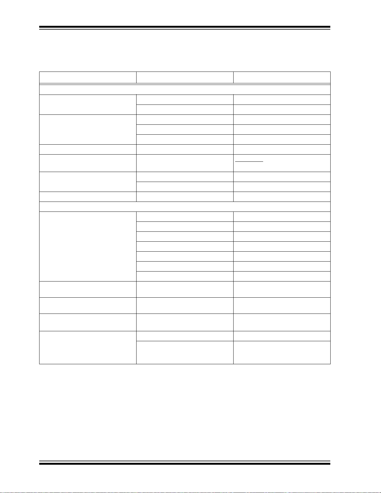
CONVENTIONS USED IN THIS GUIDE
This manual uses the following docum entat io n conven tion s:
DOCUMENTATION CONVENTIONS
Description Represents Examples
Arial font:
®
Italic characters Referenced books MPLAB
Emphasized text ...is the only compiler...
Initial caps A window the Output window
A dialog the Settings dialog
A menu selection select Enable Programmer
Quotes A field name in a window or dialog “Save project before build”
Underlined, italic text with right
A menu path File>Save
angle bracket
Bold characters A dialog button Click OK
A tab Click the Power tab
Text in angle brackets < > A key on the keyboard Press <Enter>, <F1>
Courier New font:
Plain Courier New
Sample source code
Filenames
File paths
Keywords
Command-line options
Bit values
Constants (in source code)
Italic Courier New A variable argument
#define START
autoexec.bat
C:\mcc18\h
_asm, _endasm, static
-Opa+, -Opa0, 1
0xFF, ‘A’
file.o, where
valid filename
Square brackets [ ] Optional arguments
Curly brackets and pipe
character: { | }
Choice of mutually exclusiv e
arguments; an OR selection
Ellipses... Replaces repeated text
Represents code supplied by user
mcc18 [options] file
[options]
errorlevel {0|1}
var_name [, var_name...]
void main (void)
{ ...
}
IDE User’s Guide
file can be any
DS61159A-page 6 2010 Microchip Technology Inc.
Page 7

RECOMMENDED READING
This user’s guide describes how to use the starter kit. The following Microchip
documents are available and recommended as supplemental reference resources.
Release Notes for Starter Kit
For the latest information on the starter kit, open the PIC32 Starter Kit Release
Notes.htm
C:\Microchip Starter Kits\PIC32 Starter Kits\documentation
The file generally contains the most current update information, as well as any issues
that may not have been available when this user’s guide was published.
PIC32MX3XX/4XX Family Data Sheet (DS61143) and PIC32MX5XX/6XX/7XX Family Data Sheet (DS61156)
Consult these documents for detailed information on PIC32 devices. Reference
information found in these data sheets includes:
• Device memory maps
• Device pinout and packaging details
• Device electrical speci fic ati on s
• List of peripherals included on the devices
located in either the root directory of the PIC32 Starter Kit CD or (default):
Preface
MPLAB® C Compiler for PIC32 User’s Guide (DS51686)
This document, formerly the “MPLAB C32 C Compiler for PIC32 User’s Guide”, details
the use of Microchip’s MPLAB C Compiler for PIC32 to develop an application.
MPLAB® IDE User’s Guide (DS51519)
Consult this document for more information pertaining to the installation and
implementation of the MPLAB IDE software, as well as the MPLAB Editor and MPLAB
SIM Simulator software that are included with it.
Universal Serial Bus Specificati on and Associated Documents
The Universal Serial Bus is defined by the USB 2.0 specification and its associated
supplements and class-specific documents. These documents are available from the
USB Implementers Forum. See their website at http://www.usb.org.
THE MICROCHIP WEB SITE
Microchip provides online support via our web site at http://www.microchip.com. This
web site makes files and information easily available to customers. Accessible by most
Internet browsers, the web site contains the following information:
• Product Support – Data sheets and errata, application notes and sample
programs, design resources, user’s guides and hardware support documents,
latest software releases and archived software
• General Technical Support – Frequently Asked Questions (FAQs), technical
support requests, online discussion groups, Microchip consultant program
member listings
• Business of Microchip – Product selector and ordering guides, latest Microchip
press releases, listings of seminars and events; and listings of Microchip sales
offices, distributors and factory representatives
2010 Microchip Technology Inc. DS61159A-page 7
Page 8

PIC32 Starter Kit User’s Guide
DEVELOPMENT SYSTEMS CUSTOMER CHANGE NOTIFICATION SERVICE
Microchip’s customer notification service helps keep customers current on Microchip
products. Subscribers will receive e-mail notification whenever there are changes,
updates, revisions or errata related to a specified product family or development tool of
interest.
To register, access the Microchip web site at http://www.microchip.com, click
Customer Change Notification and follow the registration instructi ons.
The Development Systems product group categories are:
• Compilers – The latest information on Microchip C compilers and other language
tools. These include the MPLAB C18 and MPLAB C30 C compilers, and MPLAB
C Compiler for PIC32; ASM32, MPASM™ and MPLAB ASM30 assemblers;
MPLINK™, and MPLAB LINK30, MPLAB LINK32 object linkers; and MPLIB™
and MPLAB LIB30 object librarians.
• Emulators – The latest information on Microchip in-circuit emulators. This
includes the MPLAB REAL ICE™ and MPLAB ICE 2000 in-circuit emulators.
• In-Circuit Debuggers – The latest information on the Microchip in-circuit
debuggers. This includes the MPLAB ICD 3 and PICkit™ 2.
• MPLAB IDE – The latest information on Microchip MPLAB IDE, the Windows
Integrated Development Environment for development systems tools. This list is
focused on the MPLAB IDE, MPLAB IDE Project Manager, MPLAB Editor and
MPLAB SIM simulator, as well as general editing and debugging features.
• Programmers – The latest information on Microchip programmers. These include
the MPLAB PM3 device programmer and the PICSTART
PICkit 2 developm ent pr ogrammers.
®
Plus, PICkit™ 1 and
®
CUSTOMER SUPPORT
Users of Microchip products can receive assistance through several channels:
• Distributor or Representative
• Local Sales Office
• Field Application Engineer (FAE)
• Technical Support
Customers should contact their distributor, representative or field application engineer
(FAE) for support. Local sales offices are also available to help customers. A listing of
sales offices and locations is included in the back of this document.
Technical support is available through the web site at: http://support.microchip.com
DS61159A-page 8 2010 Microchip Technology Inc.
Page 9

DOCUMENT REVISION HISTORY
Revision A (January 2010)
This is the initial release of the PIC32 Starter Kit User’s Guide.
Preface
2010 Microchip Technology Inc. DS61159A-page 9
Page 10

PIC32 Starter Kit User’s Guide
NOTES:
DS61159A-page 10 2010 Microchip Technology Inc.
Page 11

PIC32 STARTER KIT
USER’S GUIDE
Chapter 1. Introduction
Thank you for purchasing a Microchip T echnology PIC32 starter kit. The board included
in the starter kit (PIC32 (General Purpose) Starter Kit, PIC32 USB Starter Kit II, or
PIC32 Ethernet Starter Kit) provides a low-cost, modular development system for
Microchip’s line of 32-bit microcontrollers.
The starter kit comes preloaded with demonstration software for the user to explore the
new features of the PIC32. It is also expandable through a modular expansion interface, which allows the user to extend its functionality. The starter kit also supplies
on-board circuitry for full debug and programming capabilities.
This chapter covers the following topics:
• Kit Contents
• PIC32 Functionality and Features
The preprogrammed example code on the PIC32 MCU is available via download from
the Microchip web site at http://www.microchip.com. All project files have been included
so that the code may be used directly to restore the PIC32 MCU on the starter kit to its
original state (i.e., if the sample device has been reprogrammed with another program)
or so you can use the tutorial code as a platform for further experimentation. Refer to
2.2 “Installing the Starter Kit Software” for download and installation instructions.
1.1 KIT CONTENTS
1.1.1 PIC32 (General Purpose) Starter Kit
The PIC32 Starter Kit contains the following items:
• PIC32 Starter Kit Board
•USB Mini-B cable
• PIC32 Starter Kit Installation CD-ROM
1.1.2 PIC32 USB Starter Kit II
The PIC32 USB Starter Kit II contains the following items:
• PIC32 USB Starter Kit II Development Board
• USB Mini-B to full-sized A cable – USB debug cable to debug and power the
board
• USB Micro-B to full-sized A cable – PIC32 USB cable to communicate with the
PIC32 USB port
2010 Microchip Technology Inc. DS61159A-page 11
Page 12

PIC32 Starter Kit User’s Guide
1.1.3 PIC32 Ethernet Starter Kit
The PIC32 Ethernet Starter Kit contains the following items:
• PIC32 Ethernet Starter Kit development board
• USB Mini-B to full-sized A cable – USB debug cable to debug and power the
board
• USB Micro-B to full-sized A cable – PIC32 USB cable to communicate with the
PIC32 USB port
• RJ-45 CAT5 Ethernet patch cable – Ethernet CAT5 cable to communicate with the
PIC32 Ethernet port
Note: If you are missing any part of a kit, contact a Microchip sales office for assis-
tance. A list of Microchip offices for sales and service is provided on the
back page of this document.
DS61159A-page 12 2010 Microchip Technology Inc.
Page 13
1.2 PIC32 FUNCTIONALITY AND FEATURES
M
7
6
5
4
3
2
1
10
8
8
8
9
9
9
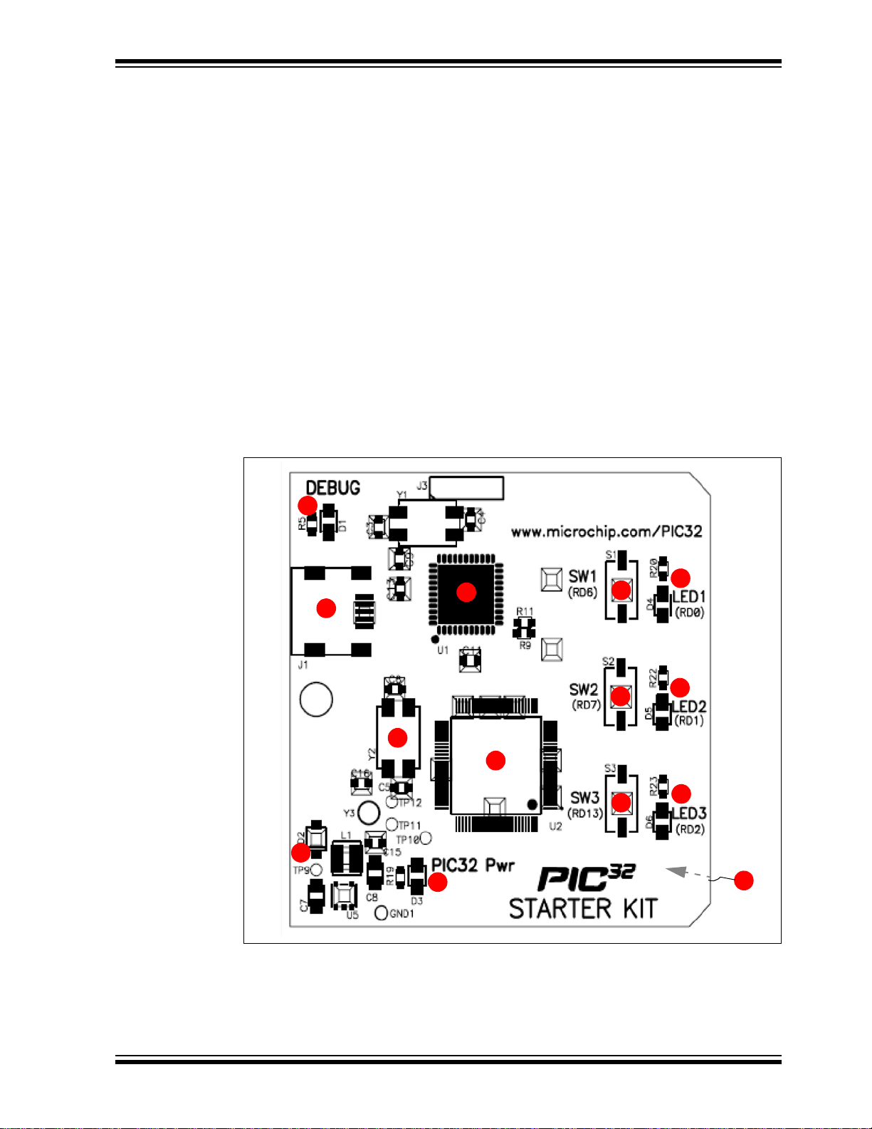
1.2.1 PIC32 (General Purpose) Starter Kit
A representation of the layout of the PIC32 Starter Kit is shown in Figure 1-1. The board
includes these key features, as indicated in the diagram:
1. PIC32MX360F512L 32-bit microcontroller.
2. Green power indicator LED.
3. Regulated +3.3V power supply for powering the starter kit board via USB or
expansion board.
4. On-board crystal for precision microcontroller clocking (8 MHz).
5. USB connectivity for on-board debugger communications.
6. PIC18LF4550 USB microcontroller for on-board debugging.
7. Orange Debug indicator LED.
8. Three push-button switches for user-defined inputs
9. Three user-defined indicato r LED s.
10. Connector for connecting various expansion boards (on the underside of board).
For details on these features, refer to Chapter 5. “Hardware”.
FIGURE 1-1: PIC32 STARTER KIT DEMO BOARD LAYOUT
.
2010 Microchip Technology Inc. DS61159A-page 13
Page 14
PIC32 Starter Kit User’s Guide
4
5
6
6
6
7
7
7
1
3
8
2
9
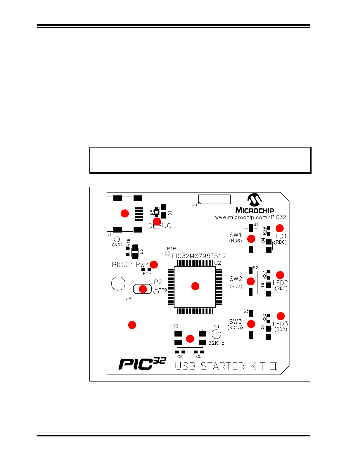
1.2.2 PIC32 USB Starter Kit II
Representations of the layout of the PIC32 USB Starter Kit II are shown in Figure 1-2
and Figure 1-3.
The top assembly of the board includes these key features, as indicated in Figure 1-2:
1. PIC32MX795F512L 32-bit microcontroller.
2. Green power indicator LED.
3. On-board crystal for precision microcontroller clocking (8 MHz).
4. USB connectivity for on-board debugger communications.
5. Orange debug indicator LED.
6. Three push button switches for user-defined inputs.
7. Three user-defined indicato r LED s.
8. USB Type A receptacle connectivity for PIC32 host-based applications.
9. HOST mode power jumper.
Note: When running USB device applications, open the jumper JP2 to prevent
possibly back-feeding voltage onto the V
another (or from one host to another).
FIGURE 1-2: PIC32 USB STARTER KIT II LAYOUT (TOP SIDE)
BUS from one port on the host to
DS61159A-page 14 2010 Microchip Technology Inc.
Page 15
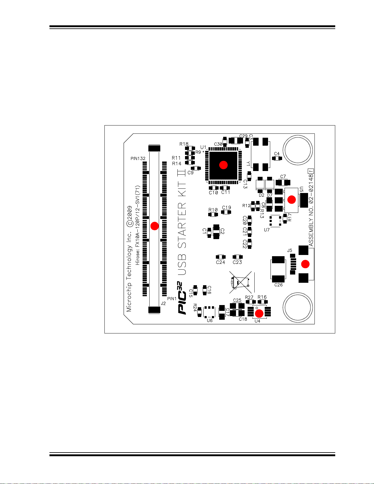
The bottom assembly of the board includes these key features, as indicated in
3
1
4
2
5
Figure 1-3:
1. PIC32MX440F512H USB microcontroller for on-board debugging.
2. Regulated +3.3V power supply for powering the starter kit via USB or expansion
board.
3. Connector for various expansion boards.
4. USB Host and OTG power supply for powering PIC32 USB applications.
5. USB Type Micro-AB receptacle for OTG and USB device connectivity for PIC32
OTG/device-based applications.
FIGURE 1-3: PIC32 USB STARTER KIT II LAYOUT (UNDERSIDE)
2010 Microchip Technology Inc. DS61159A-page 15
Page 16
PIC32 Starter Kit User’s Guide
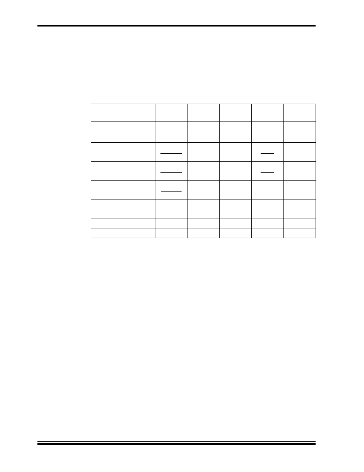
T able 1-1 shows the 100-pin to J2 connector serial communication mapping for the key
digital modules available on the PIC32 device.
Serial communication module pins are multiplexed. These pins can be used for a single
serial communication module or can be split between two serial communication
modules. For example, four pins can be selected for the UART module with flow
control, or the UART module can be selected without flow control, which uses only two
pins, leaving two pins available for use by the I
TABLE 1-1: J2 CONNECTOR MAP FOR SERIAL COMMUNICATIONS
2
C™, SPI or ECAN™ modules.
PIC32 Pin
10 45 U2ARTS U2BTX — SCK2A —
11 47 U2ARX — SDA2A SDI2A —
12 49 U2ATX — SCL2A SDO2A —
14 51 U2ACTS
39 106 U3ARTS
40 108 U3ACTS
47 94 U1ACTS
48 92
49 110 U3ARX — SDA3A SDI3A —
50 112 U3ATX — SCL3A SDO3A —
52 88 U1ARX — SDA1A SDI1A —
53 90 U1ATX — SCL1A SDO1A —
J2
Connector
UARTA UARTB I2CA SPIA ECAN
U2BRX — SS2A —
U3BTX — SCK3A AC1TX
U3BRX — SS3A AC1RX
U1BRX — SS1A —
U1ARTS U1BTX — SCK1A —
™
DS61159A-page 16 2010 Microchip Technology Inc.
Page 17
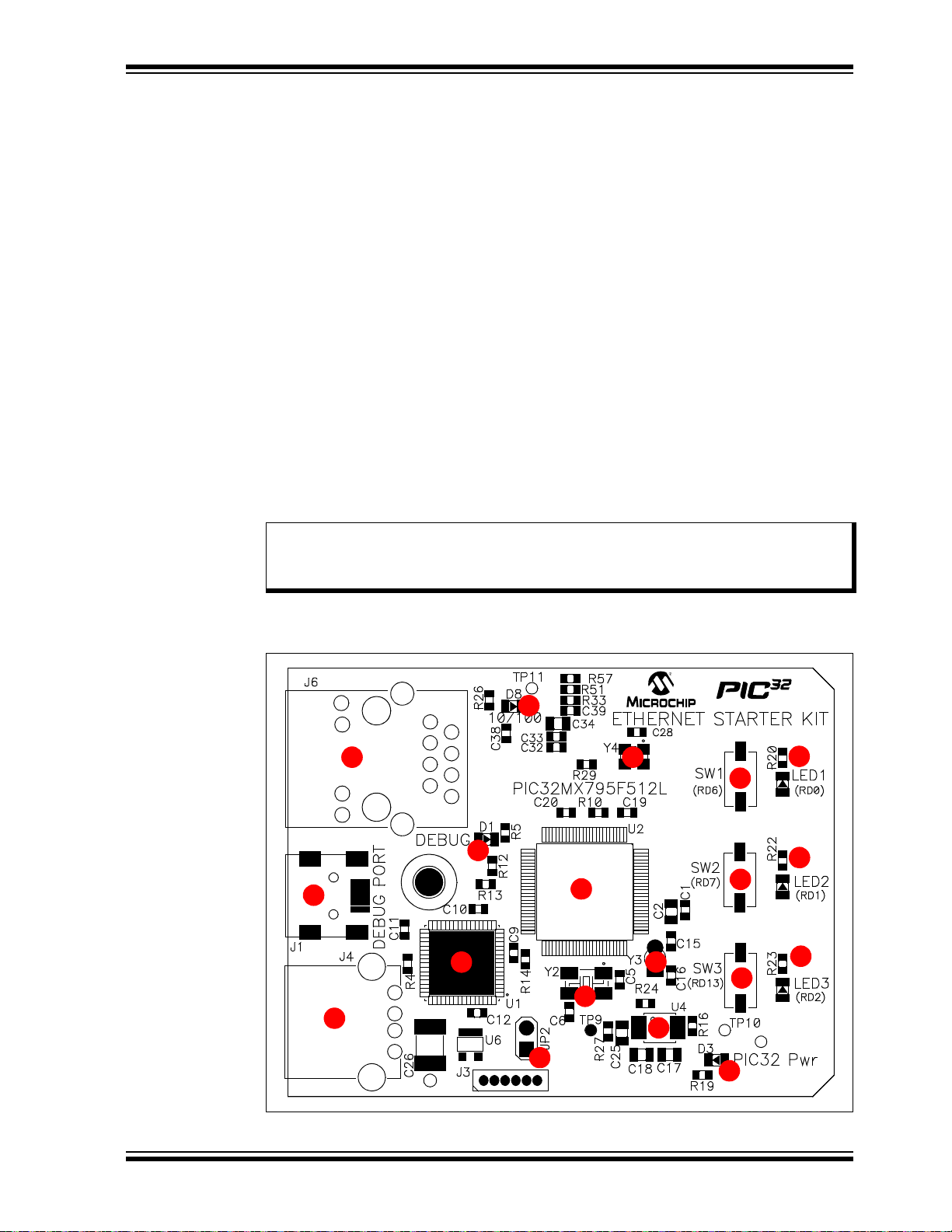
1.2.3 PIC32 Ethernet Starter Kit
4
5
6
7
7
7
1
3
10
2
9
8
8
8
11
12
13
14
15
Representations of the layout of the PIC32 Ethernet Starter Kit are shown in Figure 1-4
and Figure 1-5.
The top assembly of the board includes these key features, as indicated in Figure 1-4:
1. PIC32MX795F512L 32-bit microcontroller.
2. PIC32MX440F512H USB microcontroller for on-board debugging.
3. Green power indicator LED.
4. On-board crystal for precision microcontroller clocking (8 MHz).
5. USB connectivity for on-board debugger communications.
6. Orange debug indicator LED.
7. Three push button switches for user-defined inputs.
8. Three user-defined indicato r LED s.
9. USB Type A receptacle connectivity for PIC32 host-based applications.
10. HOST mode power jumper.
11. RJ-45 Ethernet port.
12. Ethernet 10/100 bus speed indicator LED.
13. 50 MHz Ethernet PHY oscillator.
14. 32 kHz oscillator (optional).
15. USB Host and OTG power supply for powering PIC32 USB applications.
Note: When running self-powered USB device applications, open the jumper JP2
to prevent possibly back-feeding voltage onto the V
the host to another (or from one host to another).
BUS from one port on
For details on these features, refer to Chapter 5. “Hardware”.
FIGURE 1-4: PIC32 ETHERNET STARTER KIT LAYOUT (TOP SIDE)
2010 Microchip Technology Inc. DS61159A-page 17
Page 18
PIC32 Starter Kit User’s Guide
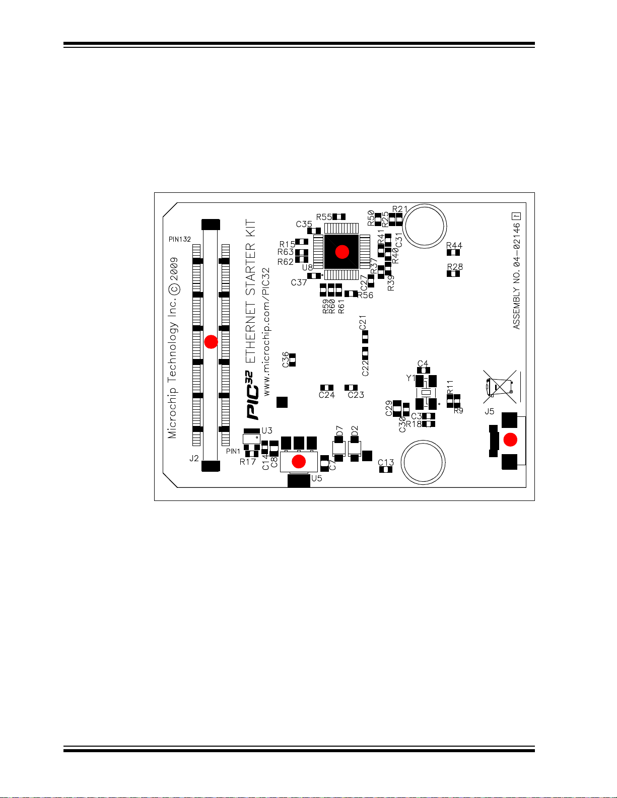
3
1
4
2
The bottom assembly of the board includes these key features, as indicated in
Figure 1-5:
1. Regulated +3.3V power supply for powering the starter kit via USB or expansion
board.
2. Connector for various expansion boards.
3. USB Type Micro-AB receptacle for OTG and USB device connectivity for PIC32
OTG/device-based applications.
4. External Ethernet PHY.
FIGURE 1-5: PIC32 ETHERNET STARTER KIT LAYOUT (UNDERSIDE)
DS61159A-page 18 2010 Microchip Technology Inc.
Page 19

T able 1-2 shows the 100-pin to J2 connector serial communication mapping for the key
digital modules available on the PIC32 device.
Serial communication module pins are multiplexed. These pins can be used for a single
serial communication module or can be split between two serial communication
modules. For example, four pins can be selected for the UART module with flow
control, or the UART module can be selected without flow control, which uses only two
pins, leaving two pins available for use by the I
2
C, SPI or ECAN modules.
TABLE 1-2: J2 CONNECTOR MAP FOR SERIAL COMMUNICATIONS
PIC32 Pin
10 45 U2ARTS
11 47 U2ARX — SDA2A SDI2A —
12 49 U2ATX — SCL2A SDO2A —
14 51 U2ACTS
39 106 U3ARTS
40 108 U3ACTS
47 94 U1ACTS
48 92
49 110 U3ARX — SDA3A SDI3A —
50 112 U3ATX — SCL3A SDO3A —
52 88 U1ARX — SDA1A SDI1A —
53 90 U1ATX — SCL1A SDO1A —
J2
Connector
UARTA UARTB I2CA SPIA ECAN™
U2BTX — SCK2A —
U2BRX — SS2A —
U3BTX — SCK3A AC1TX
U3BRX — SS3A AC1RX
U1BRX — SS1A —
U1ARTS U1BTX — SCK1A —
2010 Microchip Technology Inc. DS61159A-page 19
Page 20

PIC32 Starter Kit User’s Guide
NOTES:
DS61159A-page 20 2010 Microchip Technology Inc.
Page 21

Chapter 2. Tutorial
This chapter is a self-paced tutorial to get you started using the starter kit. Items
discussed in this chap ter inc lud e :
• Host Computer Requirements
• Installing the Starter Kit Software
• Using the Starter Kit Out of the Box
• Starting the Tutorial Project
• Building the Project
• Programming the Device
• Running the Program
• Tutorial Program Operation
2.1 HOST COMPUTER REQUIREMENTS
To communicate with and program the starter kit, the following hardware and software
requirements must be met:
• PC-compatible system
• Two available USB ports on PC or powered USB hub
• Microsoft Windows
Ethernet Starter Kit has not been tested on the Windows NT
®
2000
operating systems.)
®
XP® or Windows Vista® operating system (The PIC32
PIC32 STARTER KIT
USER’S GUIDE
®
and Windows
2010 Microchip Technology Inc. DS61159A-page 21
Page 22
PIC32 Starter Kit User’s Guide
2.2 INS TALLING THE STARTER KIT SOFTW A RE
As a USB device, the starter kit requires very little effort to install; most of the work is
done by the operating system. Begin by closing all applications.
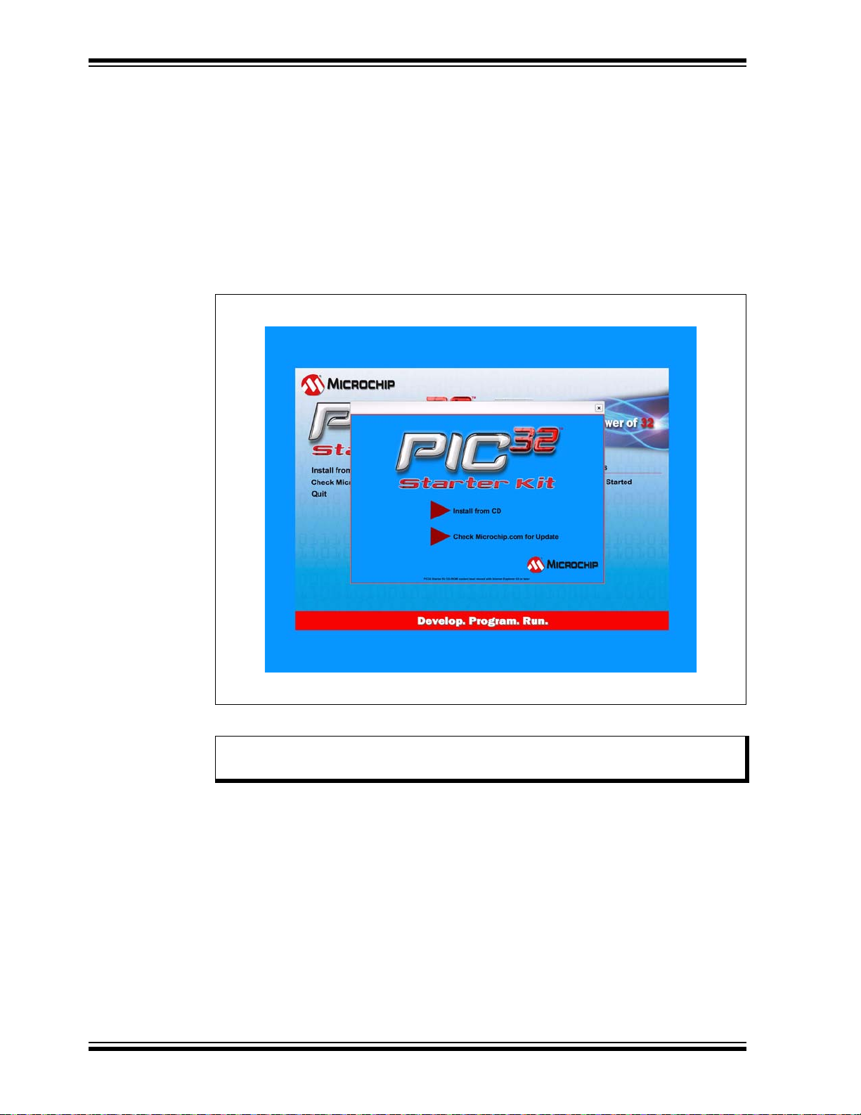
2.2.1 Install the Tools and Projects
1. Insert the PIC32 Starter Kit CD into your CD-ROM drive and click the Insta ll from
CD menu option. If the installation application does not automatically start,
navigate to the files on the CD and open
The following window appears:
FIGURE 2-1: INSTALLING THE PIC32 STARTER KIT BOARD
setup.exe.
2. Reboot your system when prompted to do so.
Note: The dialog also provides an option to check the Microchip web site for
newer versions of the starter kit software.
2.2.2 View the Getting Started Tutorial
Perform the following steps to view the tutorial:
1. After your computer has rebooted, the Getting Started Tutorial menu opens.
2. View the tutorial instructions for connecting to the starter kit board and running
the tutorial project.
If you performed the installation steps as you followed along in the Getting Started
tutorial, skip to Section 2.4 “Starting the Tutorial Project” on page 27.
If you did not, continue to the next page for instructions about how to connect the board
and install the device driver.
DS61159A-page 22 2010 Microchip Technology Inc.
Page 23

2.2.3 Connect the Starter Kit Board
Using the supplied USB cable, connect the board to an open USB port on your computer. (A USB hub that is not bus-powered can also be used.) Connect the other end
of the cable into the USB connector on the starter kit board.
Check the board: the green power LED D3 should be lit. If it is not, check the
connections at the port, hub and board.
2.2.4 Install the USB Device Driver
Note: The USB driver installation steps described here refer specifically to
installing the driver on a Microsoft Windows XP operating system.
Perform the following steps to install the USB device driver:
1. When the USB cable is connected, the “Found New Hardware Wizard” dialog
box opens, as shown in Figure 2-2. When asked whether to install the software
automatically or install from a list or specific location, select “Install software
automatically” and then click Next.
FIGURE 2-2: FOUND NEW HARDWARE WIZARD
2010 Microchip Technology Inc. DS61159A-page 23
Page 24

PIC32 Starter Kit User’s Guide
2. As shown in Figure 2-3, the next dialog box tracks the wizard as it searches for
the device. (This activity may take several seconds.) When it is done, click Next.
FIGURE 2-3: HARDWARE WIZARD – SEARCHING FOR DEVICE
3. If prompted to select a driver, select
Next to continue.
FIGURE 2-4: HARDWARE WIZARD – SELECTING THE DRIVER
mp32mxsk.inf, as shown in Figure 2-4. Click
DS61159A-page 24 2010 Microchip Technology Inc.
Page 25

4. If prompted with a dialog box for Windows Logo testing, as shown in Figure 2-5,
click Continue Anyway.
FIGURE 2-5: WINDOWS
®
LOGO TESTING
5. The next window (Figure 2-6) indicates that the installation of the software for the
starter kit is complete. Click Finish.
FIGURE 2-6: COMPLETING DEVICE DRIVER INSTALLATION
2010 Microchip Technology Inc. DS61159A-page 25
Page 26

PIC32 Starter Kit User’s Guide
2.3 USING THE STARTER KIT OUT OF THE BOX
Install the software before connecting the board to the host PC. The starter kit may be
used directly from the box as a demonstration board for the PIC32 device. The PIC32
is preprogrammed with the classic “Simon Says” game (
PIC32 device and is ready for immediate use.
2.3.1 How to Play the Game
When the USB debug cable is plugged into the starter kit’s Mini-B (debug) receptacle,
the three LEDs start blinking to indicate the start of a new game. Begin the game by
pressing one of the switches, SW1-SW3, to choose the level of game difficulty. SW3 is
the easiest, SW1 is the hardest. The goal is to imitate the light patterns as long as you
can without getting frazzled. Ultimately , you will make a mistake and all of the LEDs will
light up to signal the end of the game. After a brief pause, you can press any switch to
start a new game.
If you launch MPLAB IDE and connect to the starter kit while the game is running, the
game will stop. Further, if you perform a debug or program operation from MPLAB IDE,
the demo application will be replaced with the current MPLAB project application.
However, the game can be reloaded onto the starter kit by importing the file,
simon_says_demo.mcw, from the following location:
[install directory]\PIC32 Starter Kits\simon_says_demo
The preprogrammed example code on the PIC32 device has been included in the
starter kit demo-projects download file, which is available from the Microchip web site
(www.microchip.com). All project files have been included, so that the code may be
used directly to restore a PIC32 device to its original state (i.e., if the sample device has
been reprogrammed with another program), or so you can use the tutorial code as a
platform for further experimentation.
simon_says_demo.hex) in the
DS61159A-page 26 2010 Microchip Technology Inc.
Page 27

2.4 STARTING THE TUTORIAL PROJECT
Click the MPLAB IDE icon on your computer desktop. MPLAB IDE opens with the
starter kit tutorial project loaded, as shown in Figure 2-7. If MPLAB IDE does not have
the starter kit tutorial project loaded, select File>Open Workspace...
and browse to the desired tutorial project file:
• PIC32 (General Purpose) Starter Kit:
[install directory]\PIC32 Starter Kits\Starter_Kit_Tutorial\
starter_kit_tutorial - PIC32 Starter Kit.mcw
(or browse to the file path you used when you installed MPLAB IDE).
• PIC32 USB Starter Kit II:
[install directory]\PIC32 Starter Kits\Starter_Kit_Tutorial\
starter_kit_tutorial - PIC32 USB Starter Kit II.mcw
(or browse to the file path that you used when you installed MPLAB IDE).
• PIC 32 Ethernet Starter Kit:
[install directory]\PIC32 Starter Kits\Starter_Kit_Tutorial\
starter_kit_tutorial - PIC32 Ethernet Starter Kit.mcw
(or browse to the file path you used when you installed MPLAB IDE).
The pane on the left of the MPLAB IDE interface displays project files, the ‘
‘
.a’ files that are used to build an application. The project files are organized by type
into folders.
“Starter Kit Found” should be displayed in the “Output” pane of the MPLAB IDE inter-
face. If you do not see this message, select Debugger>Select Tool>PIC32MX Starter
Kit from the menu bar. If that sequence fails to find the project, check the driver
installation, as well as the connections between the hardware and the PC.
from the menu bar
.c’, ‘.h’ and
2010 Microchip Technology Inc. DS61159A-page 27
Page 28

PIC32 Starter Kit User’s Guide
FIGURE 2-7: MPLAB® IDE WORKSPACE
DS61159A-page 28 2010 Microchip Technology Inc.
Page 29

2.5 BUILDING THE PROJECT
From the menu bar of the main MPLAB IDE window, click Project>Make. The build
Output window displays, as shown in Figure 2-8.
Observe the progress of the build. When the “BUILD SUCCEEDED” message displays,
you are ready to program the device.
FIGURE 2-8: BUILD OUTPUT WINDOW
2010 Microchip Technology Inc. DS61159A-page 29
Page 30

PIC32 Starter Kit User’s Guide
2.6 PROGRAMMING THE DEVICE
2.6.1 Program the Device
Click on the Program All Memories icon on the Program Device Tool Bar, as shown in
Figure 2-9).
FIGURE 2-9: PROGRAM DEVICE TOOL BAR
A Programming Warning window (Figure 2-10) opens to warn you about overwriting
the memory. Click Yes.
FIGURE 2-10: PROGRAM MING WARNING WINDOW
The Output window (Figure 2-11) tracks the progress of the output. A “Done” entry
indicates that the programming of the device is complete.
FIGURE 2-11: OUTPUT WINDOW
DS61159A-page 30 2010 Microchip Technology Inc.
Page 31

2.7 RUNNING THE PROGRAM
Either clic k Debugger>Run from the menu bar of the MPLAB IDE or click the Run icon
(the turquoise triangle) on the Debug Tool Bar (Figure 2-12) to run the new program.
FIGURE 2-12: DEBUG WINDOW
2.8 T UTORIAL PROGRAM OPERATION
The starter kit tutorial demonstrates a simple application. The program responds
according to the user input menu. The program prints the available menu choices to
the starter kit Output window in the MPLAB IDE. The program flow is shown in
Figure 2-13.
2010 Microchip Technology Inc. DS61159A-page 31
Page 32

PIC32 Starter Kit User’s Guide
Power Up
D is pla y th e Bu ild
Da te a nd T im e
Ask user for the
menu choice
Is Menu choice ‘e’
or ‘E’?
Ask user for the string
of maximum 256
characters
Display the user string back to
the output w indow
Return
No
Yes
Initia liz e th e L E Ds
Is “repe at” == ‘x’
Is Menu choice ‘r’
or ‘R’?
Is Menu choice ‘o’
or ‘O’?
Is Menu choice ‘g’
or ‘G’?
Is M e n u ch o ice ‘x’
or ‘X’?
Toggle the RED
LED
Toggle the
ORANGE LED
Toggle the
GREEN LED
Display that the
user choice is
invalid and Toggle
all the LEDs once.
Dis pla y th a t th e
program has
terminated
Make repeat = ‘x’
Yes
Yes
Yes
Yes
No
No
No
No
Yes
No
FIGURE 2-13: PIC32MX TUTORIAL PROGRAM FLOWCHART
DS61159A-page 32 2010 Microchip Technology Inc.
Page 33

The tutorial program includes the Debug Print Library, which facilitates print functionality. A peripheral library header file for flashing the LEDs is also included. The header
file for print functionality is
appio.h, which is automatically included by plib.h.
Depending on the macro definition given in the print header file, the debug print macros
will be expanded. The print functionality in the tutorial is routed to the Output window
on the MPLAB PIC32MX tab in the interface window. In order to achieve this, the
macro definition “PIC32_ST ARTER_KIT” is added to the MPLAB C Compiler for PIC32
options.
As the program runs, the Output window (Figure 2-14) tracks the progress.
FIGURE 2-14: OUTPUT WINDOW
After printing the menu, the application displays a prompt that requests your input, see
Figure 2-15.
FIGURE 2-15: TARGET IN WINDOW
Type your choice into the Enter Information to be Sent to Target box, and click Send.
The program responds according to the menu entry. Watch the LEDs on the starter kit
board. If your entry is incorrect, the LEDs will toggle once.
2010 Microchip Technology Inc. DS61159A-page 33
Page 34

PIC32 Starter Kit User’s Guide
NOTES:
DS61159A-page 34 2010 Microchip Technology Inc.
Page 35

Chapter 3. Create a New Project
This chapter explains how to create a new project. Items discussed in this chapter
include:
• Creating a New Project
• Building the Project
• Programming the Device
• Running the Program
After completing this chapter, you should be able to accomplish the following tasks:
• Create a project using the Project Wizard
• Assemble and link the code, and set the Configuration bits
• Set up the MPLAB IDE to use the starter kit
• Program the chip and run the program
3.1 CREATING A NEW PROJECT
The first step is to create a project and a workspace in the MPLAB IDE. Typically, there
is a single project per workspace. A project contains the files needed to build an application (i.e., source code, header files, library, etc.), and their corresponding build
options. A workspace contains one or more projects, information on the selected
device, debug/programmer tool, and MPLAB IDE configuration settings.
MPLAB IDE contains a Project Wizard to help create a new project.
You will perform the following tasks as you create a new project:
Task 1: Select a Device................................................................................... page 36
Task 2: Select the Language Toolsuite.........................................................page 37
T ask 3: Name Your Project............................................................................ page 38
T ask 4: Add Files to Your Project..................................................................page 39
Task 5: Confirm the Configuration Settings.................................................page 40
T ask 6: Build the Project ............................................................................... page 42
T ask 7: Program the Device........................................................................... page 42
T ask 8: Run the Program................................................................................ page 43
PIC32 STARTER KIT
USER’S GUIDE
2010 Microchip Technology Inc. DS61159A-page 35
Page 36

PIC32 Starter Kit User’s Guide
3.1.1 Task 1: Select a Device
1. Start MPLAB IDE.
2. Select File>Close Workspace
3. Select Project>Project Wizard...
4. In the Welcome window, click Next. The Project Wizard Step One: window is
displayed, as shown in Figure 3-1.
FIGURE 3-1: SELECTING THE DEVICE
on the menu bar, to close any open workspace.
to start the wizard.
5. From the Device drop-down list, select the desired device, PIC32MX360F512L
for the PIC32 (General Purpose) Starter Kit, or PIC32MX795F512L for the PIC32
USB Starter Kit II or PIC32 Ethernet Starter Kit.
6. Click Next. The Project Wizard Step Two: dialog box opens, as shown in
Figure 3-2.
DS61159A-page 36 2010 Microchip Technology Inc.
Page 37

FIGURE 3-2: SELECTING THE TOOLSUITE
3.1.2 Task 2: Select the Language Toolsuite
1. From the “Active Toolsuite” drop-down list, select “Microchip PIC32 C Compiler
Toolsuite”. The toolsuite includes the compiler, assembler and linker that will be
used. If the PIC32 compiler option is not available, check the “Show all installed
toolsuites” box.
2. Click Next to continue. The Project Wizard Step Three: dialog opens, as shown
in Figure 3-3.
2010 Microchip Technology Inc. DS61159A-page 37
Page 38

PIC32 Starter Kit User’s Guide
FIGURE 3-3: NAMING YOUR PROJECT
3.1.3 Task 3: Name Your Project
1. In the “Create New Project File” field, type C:\MyProject\BlinkLED.
2. Click Next and OK to continue. The Project Wizard St ep Fo ur : di al o g o p en s, a s
shown in Figure 3-4.
FIGURE 3-4: ADDING FILES TO THE PROJECT
DS61159A-page 38 2010 Microchip Technology Inc.
Page 39

3.1.4 Task 4: Add Files to Your Project
#include <plib.h> // Adds support for PIC32 Peripheral Library functions and macros
#define SYS_FREQ (80000000)
void DelayMs(unsigned int msec)
{
unsigned int tWait, tStart;
tWait=(SYS_FREQ/2000)*msec;
tStart=ReadCoreTimer();
while((ReadCoreTimer()-tStart)<tWait); // wait for the time to pass
}
int main(void)
{
/* LED setup - Turn off leds before configuring the IO pin as output */
mPORTDClearBits(BIT_0 | BIT_1 | BIT_2); // same as LATDCLR = 0x0007
/* Set RD0, RD1 and RD2 as outputs */
mPORTDSetPinsDigitalOut(BIT_0 | BIT_1 | BIT_2 ); // same as TRISDCLR = 0x0007
/* endless loop */
while(1)
{
DelayMs(100);
mPORTDToggleBits(BIT_0); // toggle LED0 (same as LATDINV = 0x0001)
DelayMs(100);
mPORTDToggleBits(BIT_1); // toggle LED1 (same as LATDINV = 0x0002)
DelayMs(100);
mPORTDToggleBits(BIT_2); // toggle LED2 (same as LATDINV = 0x0004)
};
return 0;
}
This window can be skipped, since no ‘.c’ files have been created.
1. Click Next to conti nue.
2. Click Finish on the summary screen. A project and workspace have been
created in the MPLAB IDE.
BlinkLED.mcw is the workspace file and BlinkLED.mcp is the project file.
3. Select File>New from the menu bar to create a new file. A new file is created.
4. Select File>Save As...
this case, the
C:\MyProject folder.
5. Now copy the source code provided in Example 3-1 to the
source code file is located in the PIC32 Starter Kit directory:
[install directory]\PIC32 Starter Kits\Blink_Leds
EXAMPLE 3-1: PROJECT SOURCE CODE
and save this file as ‘BlinkLED.c’ in the same folder, in
BlinkLED.c file. The
2010 Microchip Technology Inc. DS61159A-page 39
Page 40

PIC32 Starter Kit User’s Guide
6. In the Project window, right-click the Source Files folder. Select “Add Files” and
choose
Figure 3-5.
Note: The Debug Print Library is automatically included by defining
FIGURE 3-5: ADDING SOURCE FILES
BlinkLED.c to add the file to the source directory , as shown in
PIC32_STARTER_KIT as a compile time option (Project>Build
Options>Project>MPLAB PIC32 Compiler>Preprocessor Macros), and
including the file,
Plib.h, in the source file.
7. Select Debugger>Select T ool>PIC32 Starter Kit
board.
Note: Make sure that the starter kit is connected to your PC.
from the menu bar , for the Target
3.1.5 Task 5: Confirm the Configuration Settings
Select Configur e> Co nfigur ati on Bits to confirm that the configuration settings are
correct.
Typical configuration settings for the General Purpose Starter Kit are shown in
Figure 3-6.
Figure 3-7 provides the configuration settings for the PIC32 USB Starter Kit II and the
PIC32 Ethernet Starter Kit.
Note: The “Configuration Bits set in code” check box must be clear (not
checked) if the Configuration bits are set via this window and not in the
code.
The configuration settings can also be embedded in the source file.
See the “MPLAB C Compiler for PIC32 User’s Guide” (DS51686) for
information.
DS61159A-page 40 2010 Microchip Technology Inc.
Page 41

FIGURE 3-6: PIC32 (GENERAL PURPOSE) STARTER KIT CONFIGURATION BIT SETTINGS
FIGURE 3-7: PIC32 USB STARTER KIT II AND PIC32 ETHERNET STARTER KIT
CONFIGURATION BIT SETTINGS
CAUTION
Setting the starter kit configuration bits to cause the PIC32 MCU to operate
faster than the maximum 80 MHz system clock speed, may cause the PIC32
MCU to stop communicating with the starter ki t debugger. Should this occur,
run the
tion. This utility is located on the PIC32 Starter Kit CD or in the PIC32 Starter
Kit directory:
[install directory]\PIC32 Starter Kits\tools
2010 Microchip Technology Inc. DS61159A-page 41
sk_erase.exe utility to re-flash the PIC32 MCU with a default c onfigu ra-
Page 42

PIC32 Starter Kit User’s Guide
3.1.6 Task 6: Build the Project
1. Select Project>Make from the menu bar of the main MPLAB IDE window. The
build Output window appears, as shown in Figure 3-8.
2. Observe the progress of the build. When the “BUILD SUCCEEDED” message
displays, you are ready to program the device.
FIGURE 3-8: BUILD OUTPUT WINDOW
3.1.7 Task 7: Program the Device
1. Click the Program All Memories icon on the Program Device Tool Bar, as shown
in Figure 3-9.
FIGURE 3-9: PROGRAM DEVICE WINDOW
A Programming Warning window opens to warn you about overwriting the
memory, as shown in Figure 3-10. Click Yes.
FIGURE 3-10: PROGRAM MING WARNING WINDOW
DS61159A-page 42 2010 Microchip Technology Inc.
Page 43

The Output window, shown in Figure 3-11, tracks the progress of the output. A “Done”
entry signals that the programming of the device is complete.
FIGURE 3-11: OUTPUT WINDOW
3.1.8 Task 8: Run the Program
Select Debugger>Run from the menu bar of the MPLAB IDE or click the Run icon (the
turquoise triangle) on the Debug Tool Bar, as indicated in Figure 3-12, to run the new
program.
FIGURE 3-12: RUN THE PROGRAM
The starter kit LEDs blink to indicate that the program is running successfully.
2010 Microchip Technology Inc. DS61159A-page 43
Page 44

PIC32 Starter Kit User’s Guide
NOTES:
DS61159A-page 44 2010 Microchip Technology Inc.
Page 45

Chapter 4. Starter Kit Demos
This chapter provides a brief description of each demo provided with the PIC32 Starter
Kit CD. A “Getting Started” guide is provided along with each demo that describes how
to use the demo along with any special hardware configuration necessary. The “Getting
Started” guide for any given demo is located in the demo folder:
<installed-directory>\PIC32 Starter Kits\<demo-name>
Where <installed-directory> is the directory in which the starter kit was installed
and
<demo-name> is the name of the demo in question.
The demos are broken into the following categories:
• General Purpose Demos (GP)
• USB Demos (USB)
• Ethernet Demos (ETH)
4.1 DEMO APPLICATIONS
The General Purpose demos do not require any special hardware and will run on all
types of starter kits. USB demos will only run properly on starter kits that support USB
and Ethernet demos will only run on starter kits that support Ethernet.
PIC32 STARTER KIT
USER’S GUIDE
TABLE 4-1: STARTER KIT DEMO APPLICATIONS
Demo Application Description GP USB ETH
Starter_Kit_Tutorial This PIC32MX Starter Kit tutorial program demonstrates
many of the PIC32MX Starter Kit and MPLAB® IDE features.
Blink_leds This example project demonstrates how to create, build,
program and run a new project in MPLAB IDE.
simon_says_demo This is the classic “Simon Says” game pre-programmed in
the PIC32MX Starter Kit from the factory.
Hello_World The classic “Hello World” C program. This project demon-
strates a simple console output to an MPLAB IDE window
using the Debug Print Library macros.
Port_IO This simple project highlights the PIC32 Peripheral Library
macros and how to use them to configure PORT I/O port
pins as digital outputs and digital inputs as well as configure
I/O pin Change Notice, I/O pin weak pull-ups and I/O pin
Change Notice Interrupts. This project demonstrates 2
different methods for monitoring switch presses; polling and
interrupt.
Timer_Interrupts This project showcases the PIC32MX device’s 32-bit core
timer which operates at half the System Clock Frequency
and can be used for system event s such a s generat ing a tic k
timer.
PWM_DMA A slightly more challenging project, this example demon-
strates the use of 2 PWM and 2 DMA channels to automatically control and vary the intensity of 2 LEDS, without using
the CPU.
XXX
XXX
XXX
XXX
XXX
XXX
XXX
2010 Microchip Technology Inc. DS61159A-page 45
Page 46

PIC32 Starter Kit User’s Guide
TABLE 4-1: STARTER KIT DEMO APPLICATIONS (CONTINUED)
Demo Application Description GP USB ETH
USB Device – CDC –
Basic Demo
USB Device – HID – Mouse This project demonstrates the use of the USB HID Function
USB Device – Mass Storage –
SD Card Reader
USB Device – MCHPUSB –
Generic Driver Demo
USB Host – Mass Storage –
Simple Demo
USB Host – Mass Storage –
Thumb Drive Demo
USB Host – MCHPUSB –
Generic Driver Demo
Ethernet – TCPIP-BSD –
HTTP Server Demo
This project demons trates the use of the USB CDC F unction
driver to echo characters (slightly modified) by emulating a
serial port.
driver by emulating a mouse to make the cursor move “in a
circle”.
This project demonstrates the use of the MSD Function
driver by providing SD-card reader functionality.
This project demonstrates the use of the Microchip
“Generic” Function driver by emulating the original PIC18
FSUSB demo board. (Although m ost featu res of the original
board are not supported, it does demonstrate 2-way
communication.)
This project demonstra tes us e of th e USB MSD Ho st (cl ient)
driver to write a “canned” text file to a USB thumb drive.
This project demonstra tes th e use of the MSD USB Host (c lient) driver by providing a USB thumb drive browser. It is
based on the “Thumb Drive Data Logger” demo from the
Microchip Application Libraries release, but it does not
provide the “logger” functionality.
This project demonstrates the use of the Microchip
“Generic” Host (client) driver by acting as a host to the
“Generic” device demo.
This is application demonstrates the us of the BSD TCP/IP
library to implement an embedded web server.
XX
XX
XX
XX
XX
XX
XX
X
Note: All of the GP and USB demos described in Table 4-1 can also be run on a
“Legacy” USB Starter kit (using a PIC32MX460F512L microcontroller).
However, the processor selection will need to be changed.
DS61159A-page 46 2010 Microchip Technology Inc.
Page 47

Chapter 5. Hardware
This chapter describes the hardware features of the starter kit.
5.1 HARDWARE FEATURES
5.1.1 PIC32 (General Purpose) Starter Kit
The key features of the PIC32 Starter Kit are listed below. They are presented in the
order given in Section 1.2 “PIC32 Functionality and Features”. You can refer to
Figure 1-1 for their locations on the board.
5.1.1.1 PROCESSOR SUPPORT
The PIC32 Starter Kit is designed with a permanently mounted (i.e., soldered)
PIC32MX360F512L processor.
5.1.1.2 POWER SUPPLY
There are two ways to supply power to the PIC32 Starter Kit:
PIC32 STARTER KIT
USER’S GUIDE
• USB bus power connected to J1.
• An external application board with a regulated DC power supply that provides +5V
can be connected to the J2 application board connector that is provided on the
bottom side of the board.
Note: The basic PIC32 Starter Kit does not include an application board and is
intended to be USB bus powered.
One green LED (D3) is provided to show that the PIC32 microcontroller is powered up.
5.1.1.3 USB CONNECTIVITY
The PIC32 Starter Kit includes a PIC18LF4550 USB microcontroller, which provides
both USB connectivity and support for protocol translation. The PIC18LF4550 is
hard-wired to the PIC32MX device to provide two types of connectivity:
• I/O pins of PIC18LF4550 to ICSP™ pins of PIC32MX
• I/O pins of PIC18LF4550 to JTAG pins of PIC32MX
The PIC32MX Starter Kit currently uses the JTAG pins of the PIC32MX device for
programming and debugging.
5.1.1.4 SWITCHES
Push-butt on switches provide the following functionality:
• SW1: Active-low switch connected to RD6
• SW2: Active-low switch connected to RD7
• SW3: Active-low switch connected to RD13
The switches do not have any debounce circuitry and require the use of internal pull-
up resistors; this allows you to investigate debounce techniques. When Idle, the
switches are pulled high (+3.3V). When pressed, they are grounded.
2010 Microchip Technology Inc. DS61159A-page 47
Page 48

PIC32 Starter Kit User’s Guide
5.1.1.5 LEDS
The LEDs, RD0 through RD2, are connected to PORTD of the processor. The PORTD
pins are set high to light the LEDs.
5.1.1.6 OSCILLATOR OPTIONS
The installed microcontroller has an oscillator circuit connected to it. The main oscillator
uses an 8 MHz crystal (Y2) and functions as the controller’s primary oscillator. Use of
an external crystal is not required for PIC32 designs. Your design may use the internal
oscillator, if desired.
The PIC18LF4550, at the heart of the USB subsystem, is independently clocked and
has its own 8 MHz crystal (Y1).
5.1.1.7 120-PIN MODULAR EXPANSION CONNECTOR
The PIC32 Starter Kit demo board has been designed with a 120-pin modular expansion interface, which allows the board to provide basic generic functionality now, as well
as easy extendability to new technologies as they become available.
TABLE 5-1: STARTER BOARD CONNECTOR PART NUMBERS
Connector HIROSE Electric PN
Starter Board Connector FX10A-120P/12-SV1(71)
Application Board Connector FX10A-120S/12-SV(71)
DS61159A-page 48 2010 Microchip Technology Inc.
Page 49

5.1.2 PIC32 USB Starter Kit II
The key features of the PIC32 USB Starter Kit II are listed below. They are presented
in the orde r gi ven in Sec tion 1.2 “PIC32 Functionality and Features”. You can refer
to Figure 1-2 for their locations on the board.
5.1.2.1 PROCESSOR SUPPORT
The PIC32 USB Starter Kit II is designed with a permanently mounted (i.e., soldered)
PIC32MX795F512L processor.
5.1.2.2 POWER SUPPLY
There are two ways to supply power to the PIC32 USB Starter Kit II:
• USB bus power connected to USB debug connector J1.
• An external application board with a regulated DC power supply that provides +5V
can be connected to the J2 application board connector that is provided on the
bottom side of the board.
One green LED (D3) is provided to show that the PIC32 microcontroller is powered up.
5.1.2.3 DEBUG USB CONNECTIVITY
The PIC32 USB Starter Kit II includes a PIC32MX440F512H USB microcontroller that
provides debugger connectivity over USB. The PIC32MX440F512H is hard wired to the
PIC32 device to provide two types of protocol translation:
• I/O pins of PIC32MX440F512H to the ICSP™ pins of the PIC32
• I/O pins of PIC32MX440F512H to the JTAG pins of the PIC32
The PIC32 USB Starter Kit II currently uses the JTAG pins of the PIC32 device for
programming and debugging.
5.1.2.4 PIC32 USB CONNECTIVITY
There are three possible ways to connect to the PIC32 USB microcontroller:
• HOST Mode
Connect the device to the Type A connector J4, located on the top side of the
starter kit. If using the Debug USB port to power the Host port, install jumper JP2
to short the back-power prevention diode. Note that a maximum of ~400 mA can
be supplied from the Debug USB port to the Host port using this method.
If the full 500 mA supply is needed, an external supply must be connected to the
application board and jumper JP2 must be removed to prevent back-powering the
Debug USB port.
• DEVICE Mode
First, connect the debug Mini-B USB cable to port J1. Next, connect the starter kit
to the host using a cable with a Type-B Micro plug to the starter kit’s Micro A/B
port J5, located on the bottom side of the starter kit. The other end of the cable
must have a Type-A plug. Connect it to a USB host. Jumper J2 should be
removed.
• OTG Mode
Connect the starter kit to the OTG device using an OTG Micro A/B cable to the
Micro A/B port J5, located on the bottom side of the starter kit. The starter kit provides an on-board power supply capable of providing 120 mA Max. This supply is
controlled by the PIC32MX795F512L microcontroller. Jumper J2 should be
removed.
2010 Microchip Technology Inc. DS61159A-page 49
Page 50

PIC32 Starter Kit User’s Guide
5.1.2.5 SWITCHES
Push button switches provide the following functionality:
• SW1: Active-low switch connected to RD6
• SW2: Active-low switch connected to RD7
• SW3: Active-low switch connected to RD13
The switches do not have any debounce circuitry and require the use of internal pull-up
resistors; this allows you to investigate software debounce techniques. When idle, the
switches are pulled high (+3.3V). When pressed, they are grounded.
5.1.2.6 LEDS
The RD0 through RD2 LEDs are connected to PORTD of the processor. The PORTD
pins are set high to light the LEDs.
5.1.2.7 OSCILLATOR OPTIONS
The installed microcontroller has an oscillator circuit connected to it. The main oscillator
uses an 8 MHz crystal (Y2) and functions as the controller’s primary oscillator. Use of
an external crystal is required to develop USB applications. The USB specification
dictates a frequency tolerance of +/- 0.25% for full speed. Non-USB applications can
use the internal oscillators. The starter kit also has provisions for an external secondary
oscillator (Y3); however, this is not populated.
The PIC32MX440F512H is independently clocked and has its own 8 MHz crystal (Y1).
5.1.2.8 120-PIN MODULAR EXPANSION CONNECTOR
The PIC32 USB Starter Kit II has been designed with a 120-pin modular expansion
interface, which allows the board to provide basic generic functionality now, and easy
extendability to new technologies as they become available.
TABLE 5-2: STARTER KIT CONNECTOR PART NUMBERS
Connector HIROSE Electric PN
Starter Kit Connector FX10A-120P/12-SV1(71)
Application Board Connector FX10A-120S/12-SV(71)
DS61159A-page 50 2010 Microchip Technology Inc.
Page 51

5.1.3 PIC32 Ethernet Starter Kit
The key features of the PIC32 Ethernet Starter Kit are listed below. They are presented
in the orde r gi ven in Sec tion 1.2 “PIC32 Functionality and Features”. You can refer
to Figure 1-4 for their locations on the board.
5.1.3.1 PROCESSOR SUPPORT
The PIC32 Ethernet Starter Kit is designed with a permanently mounted (i.e., soldered)
PIC32MX795F512L processor.
5.1.3.2 POWER SUPPLY
There are two ways to supply power to the PIC32 Ethernet Starter Kit:
• USB bus power connected to USB debug connector J1.
• An external application board with a regulated DC power supply that provides +5V
can be connected to the J2 application board connector that is provided on the
bottom side of the board.
One green LED (D3) is provided to show that the PIC32 microcontroller is powered up.
5.1.3.3 DEBUG USB CONNECTIVITY
The PIC32 Ethernet Starter Kit includes a PIC32MX440F512H USB microcontroller
that provides debugger connectivity over USB. The PIC32MX440F512H is hard-wired
to the PIC32 device to provide two types of protocol translation:
• I/O pins of PIC32MX440F512H to the ICSP™ pins of the PIC32
• I/O pins of PIC32MX440F512H to the JTAG pins of the PIC32
The PIC32 Ethernet Starter Kit currently uses the JTAG pins of the PIC32 device for
programming and debugging.
5.1.3.4 PIC32 USB CONNECTIVITY
There are three possible ways to connect to the PIC32 USB microcontroller:
• HOST Mode
Connect the device to the Type A connector J4, located on the top side of the
starter kit. If using the Debug USB port to power the Host port, install jumper JP2
to short the back-power prevention diode. Note that a maximum of ~400 mA can
be supplied from the Debug USB port to the Host port using this method.
If the full 500 mA supply is needed, an external supply must be connected to the
application board and jumper JP2 must be removed to prevent back-powering the
Debug USB port.
• DEVICE Mode
First, connect the debug Mini-B USB cable to port J1. Next, connect the starter kit
to the host using a cable with a Type-B Micro plug to the starter kit’s Micro A/B
port J5, located on the bottom side of the starter kit. The other end of the cable
must have a Type-A plug. Connect it to a USB host. Jumper J2 should be
removed.
• OTG Mode
Connect the starter kit to the OTG device using an OTG Micro A/B cable to the
Micro A/B port J5, located on the bottom side of the starter kit. The starter kit provides an on-board power supply capable of providing 120 mA Max. This supply is
controlled by the PIC32MX795F512L microcontroller. Jumper J2 should be
removed.
2010 Microchip Technology Inc. DS61159A-page 51
Page 52

PIC32 Starter Kit User’s Guide
5.1.3.5 SWITCHES
Push button switches provide the following functionality:
• SW1: Active-low switch connected to RD6
• SW2: Active-low switch connected to RD7
• SW3: Active-low switch connected to RD13
The switches do not have any debounce circuitry and require the use of internal pull-up
resistors; this allows you to investigate software debounce techniques. When idle, the
switches are pulled high (+3.3V). When pressed, they are grounded.
5.1.3.6 LEDS
The RD0 through RD2 LEDs are connected to PORTD of the processor. The PORTD
pins are set high to light the LEDs.
5.1.3.7 OSCILLATOR OPTIONS
The installed microcontroller has an oscillator circuit connected to it. The main oscillator
uses an 8 MHz crystal (Y2) and functions as the controller’s primary oscillator. Use of
an external crystal is required to develop USB applications. The USB specification
dictates a frequency tolerance of +/- 0.25% for full speed. Non-USB applications can
use the internal oscillators. The starter kit also has provisions for an external secondary
32 kHz oscillator (Y3); however, this is not populated. A suitable oscillator, the ECS3X8, can be obtained from Digi-Key: Part no. X801-ND CMR200TB32.768KDZFTR.
The PIC32MX440F512H is independently clocked and has its own 8 MHz crystal (Y1).
5.1.3.8 120-PIN MODULAR EXPANSION CONNECTOR
The PIC32 Ethernet Starter Kit has been designed with a 120-pin modular expansion
interface, which allows the board to provide basic generic functionality now, and easy
extendability to new technologies as they become available.
TABLE 5-3: STARTER KIT CONNECTOR PART NUMBERS
Connector HIROSE Electric PN
Starter Kit Connector FX10A-120P/12-SV1(71)
Application Board Connector FX10A-120S/12-SV(71)
5.1.3.9 ETHERNET PHY
The PIC32 Ethernet Starter Kit has been designed with a National DP83848 PHY for
connecting the Starter Kit using an RJ-45 cable to a network. The interface between
the PHY and the PIC32 has been configured for the industry standard RMII interface
and has been isolated from the Modular Expansion Connector. LED D8 indicates the
Ethernet bus speed. When lit, the bus speed is 100 Mb/s; when off, the bus speed is
10 Mb/s.
DS61159A-page 52 2010 Microchip Technology Inc.
Page 53

PIC32 STARTER KIT
PIC32MX360F512L
PIC18LF4550
ICSP™
JTAG
Power
Supply
+3.3V
VUSB or
+5V_EXT
Switches
LEDs
USB
Application Bd. Connector
USER’S GUIDE
Appendix A. Board Layout and Schematics
A.1 PIC32 (GENERAL PURPOSE) STARTER KIT DEVELOPMENT BOARD
BLOCK DIAGRAM
FIGURE A-1: HIGH-LEVEL BLOCK DIAGRAM OF THE PIC32 STARTER KIT
2010 Microchip Technology Inc. DS61159A-page 53
Page 54

PIC32 Starter Kit User’s Guide
M
A.2 PIC32 (GENERAL PURPOSE) STARTER KIT BOARD LAYOUT
FIGURE A-2: PIC32 (GENERAL PURPOSE) STARTER KIT BOARD LAYOUT (TOP ASSEMBLY)
DS61159A-page 54 2010 Microchip Technology Inc.
Page 55

2010 Microchip Technology Inc. DS61159A -page 55
A.3 PIC32 (GENERAL PURPOSE) STARTER KIT BOARD SCHEMATICS
FIGURE A-3: PIC32 STARTER KIT SCHEMATIC, SHEET 1 OF 6 (PIC32MX CPU)
Page 56

DS61159A-page 56 2010 Microchip Technology Inc.
FIGURE A-4: PIC32 STARTER KIT SCHEMATIC, SHEET 2 OF 6 (PIC18LF4550 DEBUG CPU)
PIC32 Starter Kit User’s Guide
Page 57

FIGURE A-5: PIC32 STARTER KIT SCHEMATIC, SHEET 3 OF 6
(APPLICATION BOARD CONNECTOR)
2010 Microchip Technology Inc. DS61159A-page 57
Page 58

PIC32 Starter Kit User’s Guide
FIGURE A-6: PIC32 STARTER KIT SCHEMATIC, SHEET 5 OF 6
(SWITCHES AND LEDS)
DS61159A-page 58 2010 Microchip Technology Inc.
Page 59

FIGURE A-7: PIC32 STARTER KIT SCHEMATIC, SHEET 6 OF 6 (POWER SUPPLY)
2010 Microchip Technology Inc. DS61159A-page 59
Page 60

PIC32 Starter Kit User’s Guide
PIC32MX795F512L
PIC32MX440F512H
ICSP™
JTAG
V
USB
(1)
or
+5V_EXT
Debug USB
Application Board Connector
Switches
LEDs
+5V EXT
V
USB or
+5V_EXT
+3.3V
USB OTG
Device Power
Supply
120 ma Max
USB Host
Power Supply
Device/OTG
(Type Micro A/B)
Host
(Type A)
Note 1: From Debugger USB Port
+3.3V
Power
Supply
A.4 PIC32 USB STARTER KIT II DEVELOPMENT BOARD BLOCK DIAGRAM
FIGURE A-8: HIGH-LEVEL BLOCK DIAGRAM OF THE PIC32 USB STARTER KIT II BOARD
DS61159A-page 60 2010 Microchip Technology Inc.
Page 61

A.5 PIC32 USB STARTER KIT II BOARD LAYOUT
FIGURE A-9: PIC32 USB STARTER KIT II LAYOUT (TOP ASSEMBLY)
2010 Microchip Technology Inc. DS61159A-page 61
Page 62

PIC32 Starter Kit User’s Guide
FIGURE A-10: PIC32 USB STARTER KIT II LAYOUT (BOTTOM ASSEMBLY)
DS61159A-page 62 2010 Microchip Technology Inc.
Page 63

A.6 PIC32 USB STARTER KIT II BOARD SCHEMATICS
FIGURE A-11: PIC32 USB STARTER KIT II SCHEMATICS (SHEET 1 OF 3)
2010 Microchip Technology Inc. DS61159A-page 63
Page 64

PIC32 Starter Kit User’s Guide
FIGURE A-12: PIC32 USB STARTER KIT II SCHEMATICS (SHEET 2 OF 3)
DS61159A-page 64 2010 Microchip Technology Inc.
Page 65

FIGURE A-13: PIC32 USB STARTER KIT II SCHEMATICS (SHEET 3 OF 3)
2010 Microchip Technology Inc. DS61159A-page 65
Page 66

PIC32 Starter Kit User’s Guide
PIC32MX795F512L
PIC32MX440F512H
ICSP™
JTAG
V
USB
(1)
or
+5V_EXT
Debug USB
Application Board Connector
Switches
LEDs
+5V EXT
V
USB or
+5V_EXT
+3.3V
USB OTG
Device Power
Supply
120 ma Max
USB Host
Power Supply
Device/OTG
(Type Micro A/B)
Host
(Type A)
Note 1: From Debugger USB Port
+3.3V
Power
Supply
Ethernet
PHY
10/100 Jack
A.7 PIC32 ETHERNET STARTER KIT BLOCK DIAGRAM
FIGURE A-14: HIGH-LEVEL BLOCK DIAGRAM OF THE PIC32 ETHERNET STARTER KIT
DS61159A-page 66 2010 Microchip Technology Inc.
Page 67

A.8 PIC32 ETHERNET STARTER KIT BOARD LAYOUT
FIGURE A-15: PIC32 ETHERNET STARTER KIT LAYOUT (TOP ASSEMBLY)
2010 Microchip Technology Inc. DS61159A-page 67
Page 68

PIC32 Starter Kit User’s Guide
FIGURE A-16: PIC32 ETHERNET STARTER KIT LAYOUT (BOTTOM ASSEMBLY)
DS61159A-page 68 2010 Microchip Technology Inc.
Page 69

A.9 PIC32 ETHERNET STARTER KIT BOARD SCHEMATICS
J7
J6
J4
J3
J1
J5
J8
J2
FIGURE A-17: PIC32 ETHERNET STARTER KIT (ETHERNET)
2010 Microchip Technology Inc. DS61159A-page 69
Page 70

DS61159A-page 70 2010 Microchip Technology Inc.
FIGURE A-18: PIC32 ETHERNET STARTER KIT (PIC32 DEVICE)
PIC32 Starter Kit User’s Guide
Page 71

2010 Microchip Technology Inc. DS61159A -page 71
FIGURE A-19: PIC32 ETHERNET STARTER KIT (USB HOST AND OTG POWER SUPPLIES)
Page 72

DS61159A-page 72 2010 Microchip Technology Inc.
FIGURE A-20: PIC32 ETHERNET STARTER KIT (DEBUGGER)
PIC32 Starter Kit User’s Guide
Page 73

2010 Microchip Technology Inc. DS61159A -page 73
FIGURE A-21: PIC32 ETHERNET STARTER KIT (3.3V POWER SUPPLY)
Page 74

PIC32 Starter Kit User’s Guide
FIGURE A-22: PIC32 ETHERNET STARTER KIT (APPLICATION BOARD CONNECTOR)
DS61159A-page 74 2010 Microchip Technology Inc.
Page 75

Index
PIC32 STARTER KIT
USER’S GUIDE
A
Active Toolsuite........................................................37
B
Building the tutorial project.......................................29
C
Connect the Starter Kit Board.................................. 23
Create a Project
Build the Project................................................42
Configuration settings.......................................40
Customer Change Notification Service...................... 8
Customer Support......................................................8
D
Debug print library....................................................33
Documentation
Conventions........................................................6
H
Hardware Features
LEDs..........................................48
Oscillator Options ..................................48
PICtail Plus Card Edge Connectors.......48
Power Supply.........................................47
Processor Support.................................47
Switches ................................................47
USB Connectivity...................................47
Host Computer Requirements..................................21
, 49, 50, 51, 52
, 50, 52
, 50, 52
, 49, 51
, 49, 51
, 50, 52
, 49, 51
I
Installing the USB Device Driver..............................23
Internet Address.........................................................7
L
Language Toolsuite................................................. 37
Last Schematic ........................................................59
LEDs
Power................................................................ 23
M
Microchip Internet Web Site.......................................7
MPLAB IDE Simulator, Editor User’s Guide...............7
P
PIC32
Layout
32-bit microcontroller........................... 14, 17
Connector for expansion boards................14
Debug indicator LED............................14, 17
Ethernet 10/100 Bus Speed LED...............17
Ethernet PHY oscillator..............................17
Expansion board connector.................15
External Ethernet PHY...............................18
HOST mode power jumper.................. 14
On-board crystal.................................. 14
Optional 32 kHz oscillator..........................17
Power supply....................................... 15
Power-indicator LED............................ 14
RJ-45 Ethernet port ...................................17
Switches ..............................................14
USB connectivity.................................. 14
USB Host and OTG power supply....... 15
USB microcontroller............................. 15
USB Type A receptacle....................... 14
USB Type Micro-AB receptacle........... 15
User-defined LEDs .............................. 14
PIC32 Ethernet Starter Kit Out of the box................26
PIC32 Starter Kit Demos..........................................45
PIC32MX
Layout
32-bit microcontroller.................................13
Connector for expansion boards................13
Debug indicator LED..................................13
On-board crystal........................................13
PIC18LF4550 USB microcontroller............13
Power supply.............................................13
Power-indicator LED..................................13
Switches ....................................................13
USB connectivity........................................13
User-defined LEDs ....................................13
Preprogrammed example code................................26
print functionality......................................................33
Project Wizard..........................................................35
, 18
, 17
, 17
, 18
, 17
, 17
, 17
, 17
, 17
, 17
, 18
, 17
2010 Microchip Technology Inc. DS61159A-page 75
Page 76

PIC32 Starter Kit User’s Guide
R
Readme......................................................................7
Restore PIC32 original programming.......................26
S
Schematics
Application Board Connector............................57
PIC18LF4550 Debug CPU................................56
PIC32MX CPU..................................................55
Power Supply....................................................59
Switches and LEDs...........................................58
Starter Kit Board
Block Diagram........................................53
Connecting ........................................................23
Installing device driver ......................................23
Starter Kit Layout
Bottom Assembly.............................15
Top Assembly............................14
Starter Kit Schematics
3.3V Power Supply ...........................................73
Application board connector .............................74
Debugger..........................................................72
Ethernet ............................................................69
PIC32 device.....................................................70
Sheet 1 of 3.......................................................63
Sheet 2 of 3.......................................................64
Sheet 3 of 3.......................................................65
USB Host and OTG power supplies..................71
, 60, 66
, 18, 62, 68
, 17, 54, 61, 67
T
Tutorial Program Operation......................................31
Tutorial Project
Program operation ............................................31
Programming the device...................................30
Starting..............................................................27
U
USB
Connectivity........................................... 47
, 49, 51
W
WWW Address...........................................................7
DS61159A-page 76 2010 Microchip Technology Inc.
Page 77

NOTES:
Index
2010 Microchip Technology Inc. DS61159A-page 77
Page 78

Worldwide Sales and Service
AMERICAS
Corporate Office
2355 West Chandler Blvd.
Chandler, AZ 85224-6199
Tel: 480-792-7200
Fax: 480-792-7277
Techn ical Su pport:
http://support.microchip.com
Web Address:
www.microchip.com
Atlanta
Duluth, GA
Tel: 678-957-9614
Fax: 678-957-1455
Boston
Westborough, MA
Tel: 774-760-0087
Fax: 774-760-0088
Chicago
Itasca, IL
Tel: 630-285-0071
Fax: 630-285-0075
Cleveland
Independence, OH
Tel: 216-447-0464
Fax: 216-447-0643
Dallas
Addison, TX
Tel: 972-818-7423
Fax: 972-818-2924
Detroit
Farmington Hills, MI
Tel: 248-538-2250
Fax: 248-538-2260
Kokomo
Kokomo, IN
Tel: 765-864-8360
Fax: 765-864-8387
Los Angeles
Mission Viejo, CA
Tel: 949-462-9523
Fax: 949-462-9608
Santa Clara
Santa Clara, CA
Tel: 408-961-6444
Fax: 408-961-6445
Toronto
Mississauga, Ontario,
Canada
Tel: 905-673-0699
Fax: 905-673-6509
ASIA/PACIFIC
Asia Pacific Office
Suites 3707-14, 37th Floor
To wer 6, The Gateway
Harbour City, Kowloon
Hong Kong
Tel: 852-2401-1200
Fax: 852-2401-3431
Australia - Sydney
Te l: 61-2-9868-6733
Fax: 61-2-9868-6755
China - Beijing
Te l: 86-10-8528-2100
Fax: 86-10-8528-2104
China - Chengdu
Te l: 86-28-8665-5 511
Fax: 86-28-8665-7889
China - Hong Kong SAR
Tel: 852-2401-1200
Fax: 852-2401-3431
China - Nanjing
Te l: 86-25-8473-2460
Fax: 86-25-8473-2470
China - Qingdao
Tel: 86-532-8502- 7355
Fax: 86-532-8502-7205
China - Shanghai
Te l: 86-21-5407-5533
Fax: 86-21-5407-5066
China - Shenyang
Te l: 86-24-2334-2829
Fax: 86-24-2334-2393
China - Shenzhen
Tel: 86-755-8203- 2660
Fax: 86-755-8203-1760
China - Wuhan
Te l: 86-27-5980-5300
Fax: 86-27-5980-5118
China - Xiamen
Tel: 86-592-2388138
Fax: 86-592-2388130
China - Xian
Te l: 86-29-8833-7252
Fax: 86-29-8833-7256
China - Zhuhai
Tel: 86-756-3210040
Fax: 86-756-3210049
ASIA/PACIFIC
India - Bangalore
Tel: 91-80-3090-4444
Fax: 91-80-3090-4080
India - New Delhi
Tel: 91-11-4160-8631
Fax: 91-11-4160-8632
India - Pune
Tel: 91-20-2566-1512
Fax: 91-20-2566-1513
Japan - Yokohama
Tel: 81-45-471- 6166
Fax: 81-45-471-6122
Korea - Daegu
Tel: 82-53-744-4301
Fax: 82-53-744-4302
Korea - Seoul
Tel: 82-2-554-7200
Fax: 82-2-558-5932 or
82-2-558-5934
Malaysia - Kuala Lumpur
Tel: 60-3-6201-9857
Fax: 60-3-6201-9859
Malaysia - Penang
Tel: 60-4-227-8870
Fax: 60-4-227-4068
Philippines - Manila
Tel: 63-2-634-9065
Fax: 63-2-634-9069
Singapore
Tel: 65-6334-8870
Fax: 65-6334-8850
Tai wan - Hsin Chu
Tel: 886-3-6578-300
Fax: 886-3-6578-370
Taiwan - Kaohsiung
Tel: 886-7-536-4818
Fax: 886-7-536-4803
Taiwan - Taipei
Tel: 886-2-2500-6610
Fax: 886-2-2508-0102
Thailand - Bangkok
Tel: 66-2-694-1351
Fax: 66-2-694-1350
EUROPE
Austria - Wels
Tel: 43-7242-2244- 39
Fax: 43-7242-2244-393
Denmark - Copenhagen
Tel: 45-4450-2828
Fax: 45-4485-2829
France - Paris
Te l: 33-1-69-53-63-20
Fax: 33-1-69-30-90-79
Germany - Munich
Tel: 49-89-627- 144-0
Fax: 49-89-627-144-44
Italy - Milan
Tel: 39-0331-742611
Fax: 39-0331-466781
Netherlands - Drunen
Tel: 31-416-690399
Fax: 31-416-690340
Spain - Madrid
Tel: 34-91-708- 08-90
Fax: 34-91-708-08-91
UK - Wokingham
Tel: 44-118-921-5869
Fax: 44-118-921-5820
03/26/09
DS61159A-page 78 2010 Microchip Technology Inc.
 Loading...