

Page 1
PIC18F4XK20 Starter Kit
User’s Guide
© 2008 Microchip Technology Inc. DS41344B
Page 2
Note the following details of the code protection feature on Microchip devices:
• Microchip products meet the specification contained in their particular Microchip Data Sheet.
• Microchip believes that its family of products is one of the most secure families of its kind on the market today, when used in the
intended manner and under normal conditions.
• There are dishonest and possibly illegal methods used to breach the code protection feature. All of these methods, to our
knowledge, require using the Microchip products in a manner outside the operating specifications contained in Microchip’s Data
Sheets. Most likely, the person doing so is engaged in theft of intellectual property.
• Microchip is willing to work with the customer who is concerned about the integrity of their code.
• Neither Microchip nor any other semiconductor manufacturer can guarantee the security of their code. Code protection does not
mean that we are guaranteeing the product as “unbreakable.”
Code protection is constantly evolving. We at Microchip are committed to continuously improving the code protection features of our
products. Attempts to break Microchip’s code protection feature may be a violation of the Digital Millennium Copyright Act. If such acts
allow unauthorized access to your software or other copyrighted work, you may have a right to sue for relief under that Act.
Information contained in this publication regarding device
applications and the like is provided only for your convenience
and may be superseded by updates. It is your responsibility to
ensure that your application meets with your specifications.
MICROCHIP MAKES NO REPRESENTATIONS OR
WARRANTIES OF ANY KIND WHETHER EXPRESS OR
IMPLIED, WRITTEN OR ORAL, STATUTORY OR
OTHERWISE, RELATED TO THE INFORMATION,
INCLUDING BUT NOT LIMITED TO ITS CONDITION,
QUALITY, PERFORMANCE, MERCHANTABILITY OR
FITNESS FOR PURPOSE. Microchip disclaims all liability
arising from this information and its use. Use of Microchip
devices in life support and/or safety applications is entirely at
the buyer’s risk, and the buyer agrees to defend, indemnify and
hold harmless Microchip from any and all damages, claims,
suits, or expenses resulting from such use. No licenses are
conveyed, implicitly or otherwise, under any Microchip
intellectual property rights.
Trademarks
The Microchip name and logo, the Microchip logo, Accuron,
dsPIC, K
EELOQ, KEELOQ logo, MPLAB, PIC, PICmicro,
PICSTART, PRO MATE, rfPIC and SmartShunt are registered
trademarks of Microchip Technology Incorporated in the
U.S.A. and other countries.
FilterLab, Linear Active Thermistor, MXDEV, MXLAB,
SEEVAL, SmartSensor and The Embedded Control Solutions
Company are registered trademarks of Microchip Technology
Incorporated in the U.S.A.
Analog-for-the-Digital Age, Application Maestro, CodeGuard,
dsPICDEM, dsPICDEM.net, dsPICworks, dsSPEAK, ECAN,
ECONOMONITOR, FanSense, In-Circuit Serial
Programming, ICSP, ICEPIC, Mindi, MiWi, MPASM, MPLAB
Certified logo, MPLIB, MPLINK, mTouch, PICkit, PICDEM,
PICDEM.net, PICtail, PIC
32
logo, PowerCal, PowerInfo,
PowerMate, PowerTool, REAL ICE, rfLAB, Select Mode, Total
Endurance, UNI/O, WiperLock and ZENA are trademarks of
Microchip Technology Incorporated in the U.S.A. and other
countries.
SQTP is a service mark of Microchip Technology Incorporated
in the U.S.A.
All other trademarks mentioned herein are property of their
respective companies.
© 2008, Microchip Technology Incorporated, Printed in the
U.S.A., All Rights Reserved.
Printed on recycled paper.
Microchip received ISO/TS-16949:2002 certification for its worldwide
headquarters, design and wafer fabrication facilities in Chandler and
Tempe, Arizona; Gresham, Oregon and design centers in California
and India. The Company’s quality system processes and procedures
are for its PIC
devices, Serial EEPROMs, microperipherals, nonvolatile memory and
analog products. In addition, Microchip’s quality system for the design
and manufacture of development systems is ISO 9001:2000 certified.
®
MCUs and dsPIC® DSCs, KEELOQ
®
code hopping
DS41344B-page ii © 2008 Microchip Technology Inc.
Page 3

PIC18F4XK20 STARTER KIT
USER’S GUIDE
Table of Contents
Preface ........................................................................................................................... 1
Chapter 1. PIC18F4XK20 Starter Kit Overview
1.1 Overview ........................................................................................................ 5
1.2 Highlights ........................................................................................................ 5
1.3 PIC18F4XK20 Starter Kit Contents ................................................................ 5
1.4 PIC18F4XK20 Starter Kit Layout .................................................................... 6
1.4.1 Analog Input Filtering Circuit ....................................................................... 7
1.4.2 PWM Filtering from RC2 .............................................................................. 7
1.4.3 PICtail™ Daughter Board Interface ............................................................. 7
1.4.4 PICkit™ Serial Analyzer Connector ............................................................. 7
1.4.5 ICSP™ (In-Circuit Serial Programmer™) Connector .................................. 7
1.4.6 Temperature Sensor ................................................................................... 8
1.4.7 25LC1024 Serial EEPROM ......................................................................... 8
1.4.8 32.768 kHz Crystal ...................................................................................... 8
1.4.9 128x64 OLED .............................................................................................. 8
1.5 Powering the Demo Board ............................................................................. 8
1.6 Quick Start Guide ........................................................................................... 8
1.6.1 Downloading Demonstration Software ........................................................ 8
1.7 Programming Lessons ................................................................................. 10
Chapter 2. Troubleshooting
2.1 Introduction ................................................................................................... 11
2.1.1 The board does not power up. .................................................................. 11
2.1.2 Microcontroller is not executing code. ....................................................... 11
2.1.3 The microcontroller will not program. ........................................................ 11
Appendix A. Board Schematics
A.1 Introduction .................................................................................................. 13
Worldwide Sales and Service .................................................................................... 20
© 2008 Microchip Technology Inc. DS41344B-page iii
Page 4

PIC18F4XK20 Starter Kit User’s Guide
NOTES:
DS41344B-page iv © 2008 Microchip Technology Inc.
Page 5
PIC18F4XK20 Starter Kit
USER’S GUIDE
Preface
NOTICE TO CUSTOMERS
All documentation becomes dated, and this manual is no exception. Microchip tools and
documentation are constantly evolving to meet customer needs, so some actual dialogs
and/or tool descriptions may differ from those in this document. Please refer to our web site
(www.microchip.com) to obtain the latest documentation available.
Documents are identified with a “DS” number. This number is located on the bottom of each
page, in front of the page number. The numbering convention for the DS number is
“DSXXXXXA”, where “XXXXX” is the document number and “A” is the revision level of the
document.
For the most up-to-date information on development tools, see the MPLAB
Select the Help menu, and then Topics to open a list of available on-line help files.
®
IDE on-line help.
INTRODUCTION
This chapter contains general information that will be useful to know before using the
PIC18F4XK20 Starter Kit. Items discussed in this chapter include:
• Document Layout
• Conventions Used in this Guide
• Recommended Reading
• The Microchip Web Site
• Development Systems Customer Change Notification Service
• Customer Support
• Document Revision History
DOCUMENT LAYOUT
This document describes how to use the PIC18F4XK20 Starter Kit as a development
tool to emulate and debug firmware on a target board. The manual layout is as follows:
• Chapter 1. PIC18F4XK20 Starter Kit Overview – Introduces the PIC18F4XK20
Starter Kit and provides a brief description of the hardware and the new features.
• Chapter 2. Troubleshooting – Describes the common problems of the
PIC18F4XK20 Demonstration Board and their solutions.
• Appendix A. Board Schematics – Provides schematic diagrams for the
PIC18F4XK20 Demonstration Board.
© 2008 Microchip Technology Inc. DS41344B-page 1
Page 6
PIC18F4XK20 Starter Kit User’s Guide
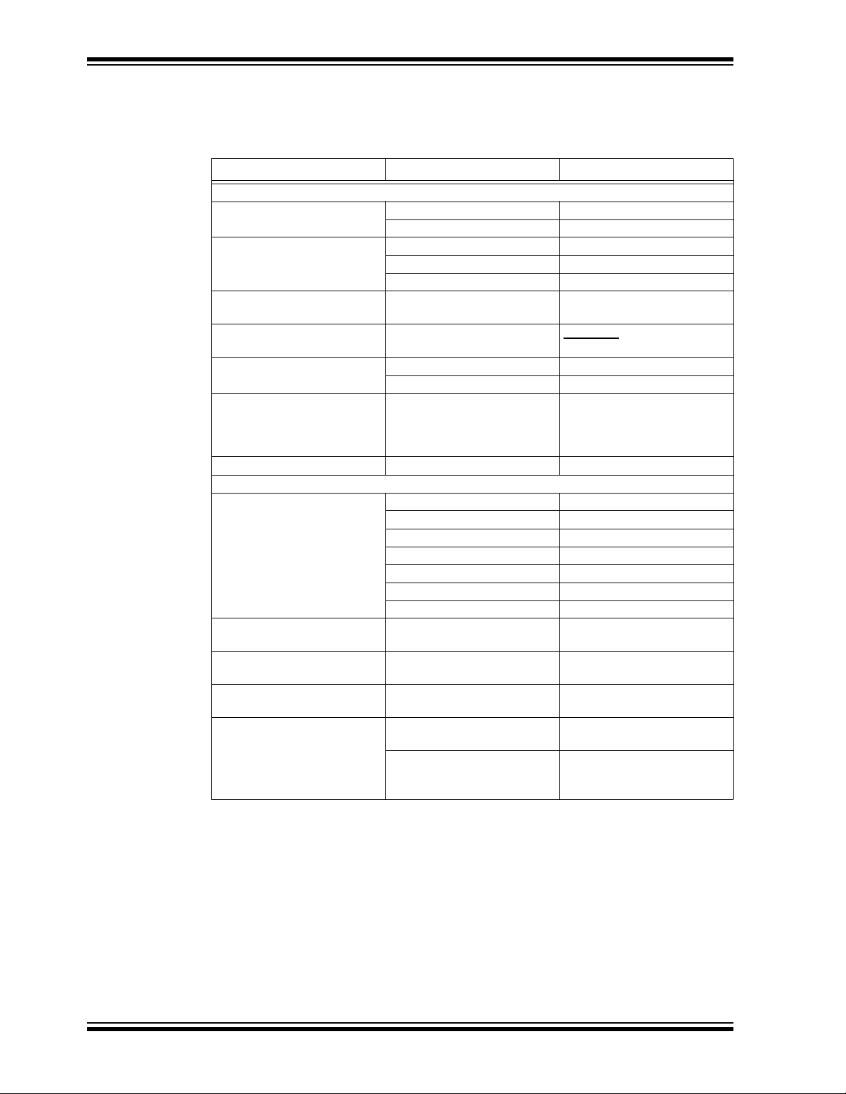
CONVENTIONS USED IN THIS GUIDE
This manual uses the following documentation conventions:
DOCUMENTATION CONVENTIONS
Description Represents Examples
Arial font:
Italic characters Referenced books MPLAB
Emphasized text ...is the only compiler...
Initial caps A window the Output window
A dialog the Settings dialog
A menu selection select Enable Programmer
Quotes A field name in a window or
dialog
Underlined, italic text with
right angle bracket
Bold characters A dialog button Click OK
N‘Rnnnn A number in verilog format,
Text in angle brackets < > A key on the keyboard Press <Enter>, <F1>
Courier New font:
Plain Courier New Sample source code #define START
Italic Courier New A variable argument file.o, where file can be
Square brackets [ ] Optional arguments mcc18 [options] file
Curly brackets and pipe
character: { | }
Ellipses... Replaces repeated text var_name [,
A menu path File>Save
A tab Click the Power tab
where N is the total number of
digits, R is the radix and n is a
digit.
Filenames autoexec.bat
File paths c:\mcc18\h
Keywords _asm, _endasm, static
Command-line options -Opa+, -Opa-
Bit values 0, 1
Constants 0xFF, ‘A’
Choice of mutually exclusive
arguments; an OR selection
Represents code supplied by
user
®
IDE User’s Guide
“Save project before build”
4‘b0010, 2‘hF1
any valid filename
[options]
errorlevel {0|1}
var_name...]
void main (void)
{ ...
}
DS41344B-page 2 © 2008 Microchip Technology Inc.
Page 7

RECOMMENDED READING
This user's guide describes how to use the PIC18F4XK20 Starter Kit. Other useful documents are listed below. The following Microchip documents are available and recommended as supplemental reference resources.
PIC18F46K20 Data Sheet (DS41303)
This data sheet summarizes the features of the PIC18F46K20. It provides essential
information needed to develop software for this device.
MCP9700/9700A and MCP9701/9701A Data Sheet (DS21942)
This data sheet summarizes the features of the MCP9700/9700A and
MCP9701/9701A. It provides essential information needed to develop software for
these devices.
MCP001/2/4 Data Sheet (DS21733)
This data sheet summarizes the features of the MCP001/2/4. It provides essential
information needed to develop software for these devices.
25LC1024 Data Sheet (DS22064)
This data sheet summarizes the features of the 25LC1024. It provides essential
information needed to develop software for this device.
Preface
THE MICROCHIP WEB SITE
Microchip provides online support via our web site at www.microchip.com. This web
site is used as a means to make files and information easily available to customers.
Accessible by using your favorite Internet browser, the web site contains the following
information:
• Product Support – Data sheets and errata, application notes and sample
programs, design resources, user’s guides and hardware support documents,
latest software releases and archived software
• General Technical Support – Frequently Asked Questions (FAQs), technical
support requests, online discussion groups, Microchip consultant program
member listing
• Business of Microchip – Product selector and ordering guides, latest Microchip
press releases, listing of seminars and events, listings of Microchip sales offices,
distributors and factory representatives
© 2008 Microchip Technology Inc. DS41344B-page 3
Page 8

PIC18F4XK20 Starter Kit User’s Guide
DEVELOPMENT SYSTEMS CUSTOMER CHANGE NOTIFICATION SERVICE
Microchip’s customer notification service helps keep customers current on Microchip
products. Subscribers will receive e-mail notification whenever there are changes,
updates, revisions or errata related to a specified product family or development tool of
interest.
To register, access the Microchip web site at www.microchip.com, click on Customer
Change Notification and follow the registration instructions.
The Development Systems product group categories are:
• Compilers – The latest information on Microchip C compilers and other language
tools. These include the MPLAB C18 and MPLAB C30 C compilers; MPASM™
and MPLAB ASM30 assemblers; MPLINK™ and MPLAB LINK30 object linkers;
and MPLIB™ and MPLAB LIB30 object librarians.
• Emulators – The latest information on Microchip in-circuit emulators.This
includes the MPLAB ICE 2000 and MPLAB ICE 4000.
• In-Circuit Debuggers – The latest information on the Microchip in-circuit
debugger, MPLAB ICD 2.
• MPLAB
Integrated Development Environment for development systems tools. This list is
focused on the MPLAB IDE, MPLAB SIM simulator, MPLAB IDE Project Manager
and general editing and debugging features.
• Programmers – The latest information on Microchip programmers. These include
the MPLAB PM3 and PRO MATE
Plus and PICkit™ 1 development programmers.
®
IDE – The latest information on Microchip MPLAB IDE, the Windows®
®
II device programmers and the PICSTART®
CUSTOMER SUPPORT
Users of Microchip products can receive assistance through several channels:
• Distributor or Representative
• Local Sales Office
• Field Application Engineer (FAE)
• Technical Support
Customers should contact their distributor, representative or field application engineer
(FAE) for support. Local sales offices are also available to help customers. A listing of
sales offices and locations is included in the back of this document.
Technical support is available through the web site at: http://support.microchip.com
DOCUMENT REVISION HISTORY
Revision A (March 2008)
• Initial Release of this Document.
Revision B (April 2008)
• Removed reference to OLED Data Sheet
DS41344B-page 4 © 2008 Microchip Technology Inc.
Page 9

Chapter 1. PIC18F4XK20 Starter Kit Overview
The PIC18F4XK20 Starter Kit is a demonstration and development tool designed for
those getting started with microcontrollers or those looking to migrate to the new
PIC18F4XK20/2XK20 family. The board is designed for general purpose applications
and includes a variety of hardware to exercise microcontroller peripherals.
1.1 OVERVIEW
The PIC18F4XK20/2XK20 is a new family of microcontrollers that take advantage of
Microchip’s latest process technology. Among the most notable of the new features are:
• lower power consumption
• high-performance operation and
•low-cost
Several firmware demos that showcase some of the features are included, as well as
a PICkit™ 2 Development Programmer, which can be used to download the demos
onto the development board.
The hardware included on the board allows for development as well. The microcontroller
that is populated on the board, the PIC18F46K20, is the superset of the PIC18F4XK20/2XK20
family. Included on the board are various analog and digital circuitry used in
microcontroller applications, in addition to a header which breaks out all signal lines for
analysis or interfacing to external devices.
PIC18F4XK20 STARTER KIT
USER’S GUIDE
1.2 HIGHLIGHTS
This chapter discusses the features of the PIC18F4XK20 Starter Kit. Topics discussed
include:
• PIC18F4XK20 Starter Kit Contents
• PIC18F4XK20 System Management Layout
• Powering the Demo Board
• Quick Start Guide
• Programming Lessons
1.3 PIC18F4XK20 STARTER KIT CONTENTS
The PIC18F4XK20 Starter Kit includes the following items:
• PIC18F4XK20 Starter Kit Board
• PIC18F4XK20 CD-ROM, which includes:
- PIC18F4XK20 Starter Kit User’s Guide
- PIC18F4XK20 Schematics and Layout
- Labs and Demo Software Source Code
- PIC18F4XK20/2XK20 Data Sheets
- 25LC1024 Data Sheet
• PICkit 2 Development Programmer
• Programming Lessons
© 2008 Microchip Technology Inc. DS41344B-page 5
Page 10
PIC18F4XK20 Starter Kit User’s Guide
If you are missing any part of the kit, please contact your nearest Microchip sales office
listed on the back of this publication.
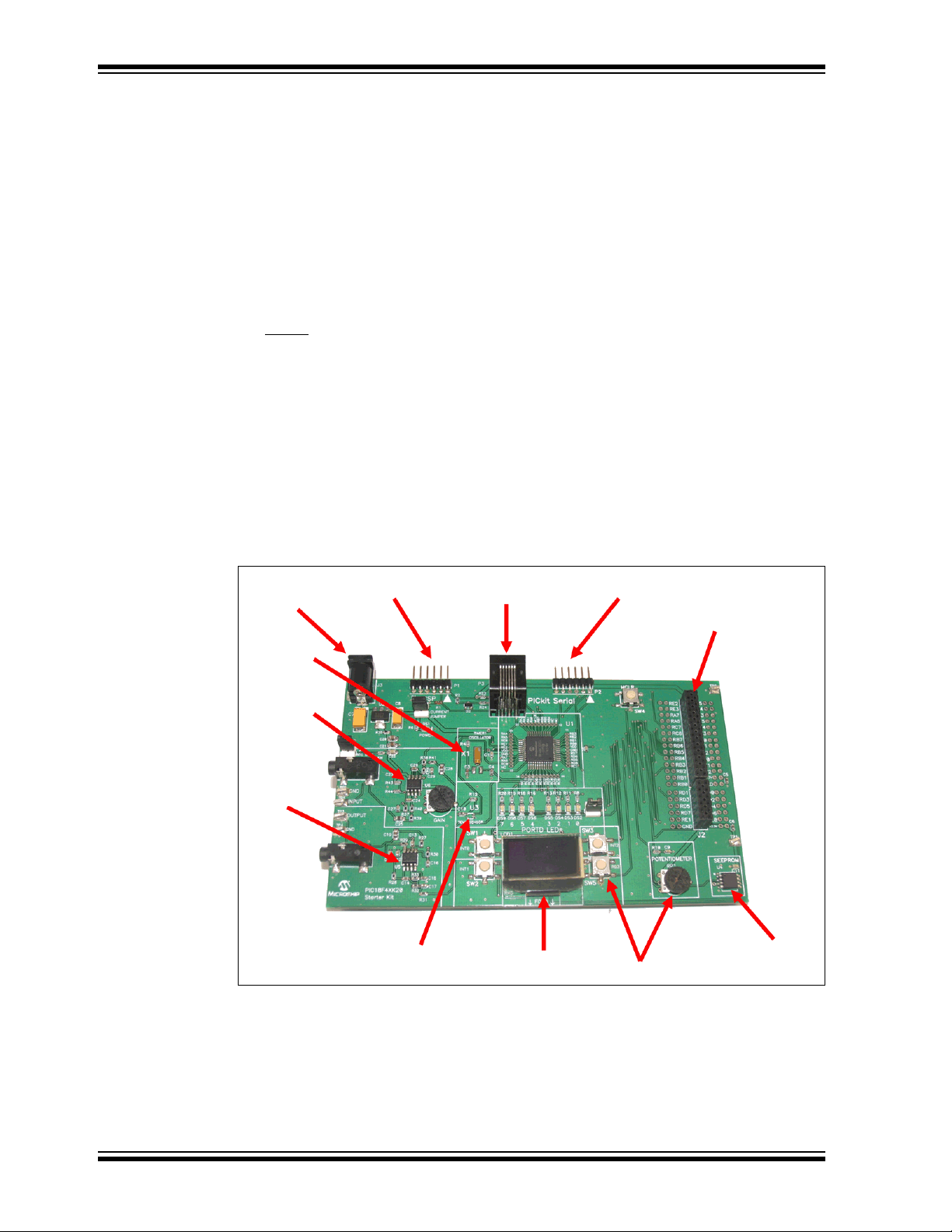
1.4 PIC18F4XK20 STARTER KIT LAYOUT
The PIC18F4XK20 Starter Kit Board is populated with a PIC18F46K20 microcontroller.
In addition, the board is also populated with the following features/components:
• 128x64 Organic LED Display (SPI)
• 32.768 kHz External Oscillator (Timer1)
• Analog Input Filtering and Gain Control into RE1 (1.4.1)
• PWM Output Filtering from RC2 (1.4.2)
• 4 Push Buttons for User Interfacing
•1 MCLR
• 8 LEDs mapped to PORTD
• Potentiometer
• 1024 KB Serial EEPROM
• PICtail™ daughter board header (breaks out all pins)
• 6-Pin ICSP™ programming capability header
• 6-Pin PICkit serial analyzer interface
• Current measurement jumper
• RJ-11 ICSP programming header
switch
FIGURE 1-1: STARTER KIT LAYOUT
TM
PICkit
+5-12V Power
32 kHz xTAL
Audio/Analog IN with
Adjustable Gain
Audio/Analog
OUT
2 Interface
MCP9700
Temperature
Sensor
ICD2 Interface
O-LED
Display
TM
PICkit
Serial
Interface
PICtail
Pushbuttons and POT
TM
Header
Serial EEPROM
DS41344B-page 6 © 2008 Microchip Technology Inc.
Page 11
PIC18F4XK20 Starter Kit Overview
1.4.1 Analog Input Filtering Circuit
The analog filtering circuit is designed for use with an electret microphone. Electret
microphones typically require biasing, which is provided by MIC bias jumper, JP3. The
analog signal generated by a typical electret microphone has a peak to peak voltage in
the single millivolts range. The analog filtering circuit has a maximum gain of 300 which
can be controlled with the potentiometer labeled GAIN and is a 2nd order low-pass filter
with a cut-off frequency of 5 kHz. Jumper JP3 needs to be removed if the analog input
is provided by input test point.
1.4.2 PWM Filtering from RC2
The microcontroller output RC2 provides an active low pass filter that can be used to
generate analog signals. A high frequency PWM output from RC2 can be pulse width
modulated to vary the amplitude of the output signal.
1.4.3 PICtail Daughter Board Interface
The PICtail daughter board interface breaks out each pin of the microcontroller in
addition to providing +V
existing PICtail daughter boards. Visit the Microchip web site to find more details on
PICtail daughter boards.
1.4.4 PICkit Serial Analyzer Connector
DD and ground. The header is designed to be compatible with
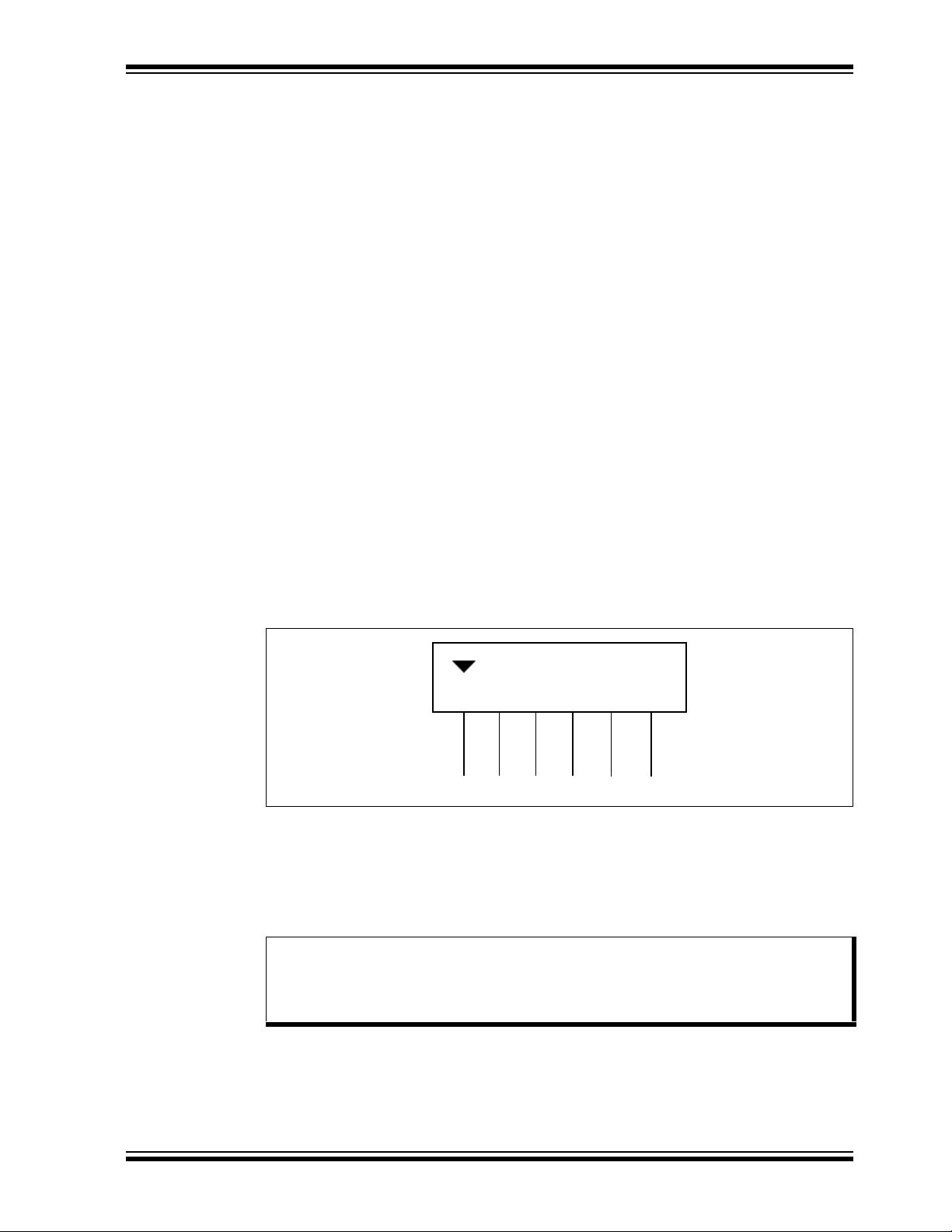
The PICkit serial analyzer connector provides pins for serial communication. The serial
communications lines are designed to be used with the PICkit serial analyzer, but are
also provided for general purpose communications as well.
The Serial Communications
pinout is shown below:
FIGURE 1-2: SERIAL COMMUNICATIONS PIN-OUT
1
TX
23
+5V
456
SDA
G
ND
SCL RX
1.4.5 ICSP™ (In-Circuit Serial Programmer™) Connector
A 6-pin ICSP programming capability and RJ-11 connectors are provided for
programming the microcontroller. The PIC18F46K20 can be programmed through
these connectors using the PICkit 2 programmer in the MPLAB ICD 2.
Note: The programming voltage on the microcontroller VPP pin must be below 9V
according to the programming specification. Protection circuitry (8.2V
Zener with 820 Ohm series resistor) is in place to ensure that V
exceed programming specifications.
PP does not
© 2008 Microchip Technology Inc. DS41344B-page 7
Page 12

PIC18F4XK20 Starter Kit User’s Guide
1.4.6 Temperature Sensor
An MCP9700 temperature sensor is located on the board. The MCP9700 is an analog
temperature sensor that provides a linear voltage output versus temperature. The
voltage output of the temperature sensor is connected to the RE1 pin of the microcontroller
1.4.7 25LC1024 Serial EEPROM
A Microchip 1024 Kbit serial reprogrammable Flash memory with both Flash and
byte-level serial EEPROM functions is provided.
The memory is accessed via a simple Serial Peripheral Interface (SPI) compatible
serial bus. The bus signals are a clock input plus separate data in and data out lines.
Access to the device is controlled by a Chip Select (CS) input on the microcontroller pin
RA6.
1.4.8 32.768 kHz Crystal
The 32.768 kHz tuning fork crystal is interfaced to the RC0/T1OSO and RC1/T1OSI
pins for use with the Timer1 peripheral.
1.4.9 128x64 OLED
The display provided on the development board is a 128x64 organic LED display. It
interfaces to the microcontroller via Serial Peripheral Interface (SPI). The controller on
the OLED is the SH1101A.
.
1.5 POWERING THE DEMO BOARD
The demonstration board can be powered in the following ways:
1. The board accepts a 2.5mm coaxial power connector in J3. Acceptable voltages
range from +5-12 V
2. The PICkit 2 Development programmer can be used to provide power at connector P1. Do not exceed current of 100 mA on the board if the PICkit 2 is being
used to power the board.
3. The PICkit Serial Analyzer can be used to provide power at connector P2. Do
not exceed a current of 100 mA on the board if the PICkit Serial Analyzer is being
used to power the board.
DC.
1.6 QUICK START GUIDE
The PIC18F4XK20 Starter Kit is preloaded with demonstration firmware. The board
must be configured as described in this section in order to use the demonstration programs
Board Setup
1. Close jumper JP1 labeled Current Jumper, JP3 labeled Mic Bias and JP2.
2. Connect a +5-12V power supply to connector J3 in the upper left portion of the
board.
1.6.1 Downloading Demonstration Software
The PIC18F4XK20 Starter Kit CD-ROM comes with 3 demonstration programs and 12
hands-on programming lessons. Using the PICkit 2 Development Programmer, demonstration firmware can be downloaded onto the demo board and the board can be
powered.
.
DS41344B-page 8 © 2008 Microchip Technology Inc.
Page 13
PIC18F4XK20 Starter Kit Overview
1. Insert the included PIC18F4XK20 Demonstration Board CD into the CD-ROM
Drive.
2. Run the installation setup for MPLAB IDE.
3. Connect the PICkit 2 programmer to the Starter Kit board and computer.
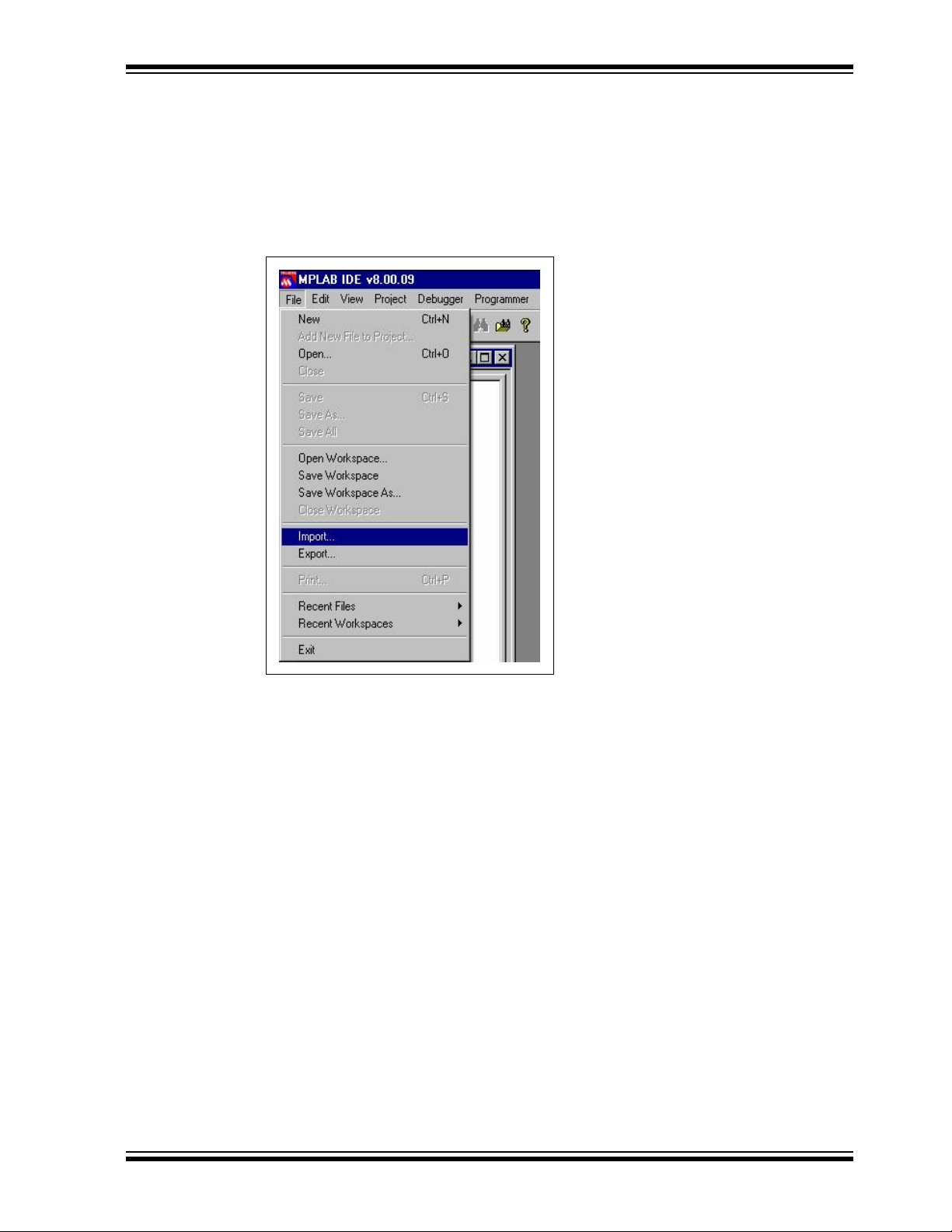
4. Start the MPLAB IDE software.
5. Click File > Import.
FIGURE 1-3: IMPORT
6. Browse to the CD-ROM drive directory Demos.
7. Select one of the several demos available (readme.txt in the Demos directory
will describe each demo) and click Open:
© 2008 Microchip Technology Inc. DS41344B-page 9
Page 14

PIC18F4XK20 Starter Kit User’s Guide
FIGURE 1-4: DEMOS AVAILABLE
8. Click Programmer > Select Programmer > PICkit 2:
FIGURE 1-5:
9. To program, click Programmer > Program.
10. Click Programmer > Release from Reset to release the M
program.
1.7 PROGRAMMING LESSONS
CLR to run the
The PIC18F4XK20 CD-ROM includes a variety of programming lessons designed for
use with the demonstration board. Insert the PIC18F4XK20 CD-ROM and browse to
the Lessons directory of the CD-ROM.
DS41344B-page 10 © 2008 Microchip Technology Inc.
Page 15

2.1 INTRODUCTION
This chapter describes common problems when using the PIC18F4XK20
Demonstration Board and their solutions.
2.1.1 The board does not power up.
Make sure that the green POWER LED has turned on. If the LED is not on, check to
see that the +9V power supply is properly connected.
2.1.2 Microcontroller is not executing code.
First check to make sure that the microcontroller has been programmed with the firmware that is intended to run. If the part is programmed, ensure that the current jumper
JP1 is in place.
2.1.3 The microcontroller will not program.
Check to make sure that the programmer/debugger is properly connected to the PC
and powered. Make sure that the board is also powered with the +9V power supply.
Programming can only occur when the current jumper JP1 is connected.
PIC18F4XK20 STARTER KIT
USER’S GUIDE
Chapter 2. Troubleshooting
© 2008 Microchip Technology Inc. DS41344B-page 11
Page 16

PIC18F4XK20 Starter Kit User’s Guide
NOTES:
DS41344B-page 12 © 2008 Microchip Technology Inc.
Page 17

PIC18F4XK20 STARTER KIT
USER’S GUIDE
Appendix A. Board Schematics
A.1 INTRODUCTION
This appendix contains the PIC18F4XK20 demonstration board schematics, broken
down into 5 sheets, as follows:
FIGURE A-1: PIC18F4XK20 DEMO BOARD SCHEMATIC DIAGRAM (SHEET 1 OF 5)
+3.3V
JP1
Current Sense
C1
0.1 uFC20.1 uF C4
1
RC7/RX
RC7
2
RD4
RD4
3
RD5
RD5
4
RD6
RD6
5
RD7
RD7
6
SS
V
7
VDD
8
RB0
RB0
9
RB1
RB1
10
RB2
RB2
11
RB3
RB3
+3.3V
TP1 +V
12 pF
RC5/MOSI
RD1
RD3
RC4/MISO
RD2
RC6/TX
41
39
43
42
44
40
RC4
RC5
RD3
RD2
RD1
RC6
U1
PIC18F46K20-I/PT
NC
NC
RB5
RB6
RB7
RB4
12
131415
161718
RB4
RB5
TP2 GND
RB7
RD0
38
RD0
MCLR
RE3
RC3/SCK
RC2
373635
RC3
RC2
RA1
RA0
20
19
RA1
RA0
RC1
34
RC1
OSCO/RA3
RA2
21
22
RA2
32 kHz
NC
RC0
OSCI/RA2
RE2
RE1
RE0
RA5
RA4
RA3
RA3
V
VDD
NC
SS
C3
12 pF
X1
33
32
31
30
29
28
27
26
25
24
23
R4
220K
RC0
RA6/SEE_NCS
RA7/OLED_NCS
RE2
RE1
RE0
RA5/ND/C
RA4/NRES
+3.3V
R1
820
TM
ICSP
P1
1
V
PP
2
VDD
3
GND
4
ICSPDAT
5
ICSPCLK
6
T1G
R2
820
K
D2
8.2
A
BZX84B8V2LT1
RA7/OLED_NCS
RA6/SEE_NCS
RC7/RX
RC6/TX
J2
RD1
RD3
RD5
RD7
RE1
BZX84B8V2LT1
RE2
RE3
RB7
RB6
RB5
RB4
RB3
RB2
RB1
RB0
RD0
RD2
RD4
RD6
RE0
RC7/RX
RC6/TX
D1
3.9V
AK
J1
1
3
5
7
9
10
11
12
14
13
16
15
18
17
20
19
22
21
23
24
25
26
27
28
+3.3V
USRT
P2
1
RX
2
+V
3
GND
4
NC
5
NC
6
TX
2
RA5/ND/C
RA4/NRES
4
RA3
6
8
RC5/MOSI
RC4/MISO
RC3/SCK
RA0
RA1
RA2
RC0
RC1
RC2
+3.3V
C5
1 uF
C6
1 uF
© 2008 Microchip Technology Inc. DS41344B-page 13
Page 18

PIC18F4XK20 Starter Kit User’s Guide
FIGURE A-2: PIC18F4XK20 DEMO BOARD SCHEMATIC DIAGRAM (SHEET 2 OF 5)
MCP9700-I/LT
DS41344B-page 14 © 2008 Microchip Technology Inc.
Page 19

Board Schematics
FIGURE A-3: PIC18F4XK20 DEMO BOARD SCHEMATIC DIAGRAM (SHEET 3 OF 5)
VDC
2
3
A
1
MCP6022
pF
6
5
MCP6022
7
© 2008 Microchip Technology Inc. DS41344B-page 15
Page 20

PIC18F4XK20 Starter Kit User’s Guide
FIGURE A-4: PIC18F4XK20 DEMO BOARD SCHEMATIC DIAGRAM (SHEET 4 OF 5)
2
1
A
3
MCP6022
6
5
MCP6022
7
DS41344B-page 16 © 2008 Microchip Technology Inc.
Page 21

Board Schematics
FIGURE A-5: PIC18F4XK20 DEMO BOARD SCHEMATIC DIAGRAM (SHEET 5 OF 5)
G1
D1S1
© 2008 Microchip Technology Inc. DS41344B-page 17
Page 22

PIC18F4XK20 Starter Kit User’s Guide
NOTES:
DS41344B-page 18 © 2008 Microchip Technology Inc.
Page 23

NOTES:
PIC18F4XK20 Starter Kit User’s Guide
© 2008 Microchip Technology Inc. DS41344B-page 19
Page 24

WORLDWIDE SALES AND SERVICE
AMERICAS
Corporate Office
2355 West Chandler Blvd.
Chandler, AZ 85224-6199
Tel: 480-792-7200
Fax: 480-792-7277
Technical Support:
http://support.microchip.com
Web Address:
www.microchip.com
Atlanta
Duluth, GA
Tel: 678-957-9614
Fax: 678-957-1455
Boston
Westborough, MA
Tel: 774-760-0087
Fax: 774-760-0088
Chicago
Itasca, IL
Tel: 630-285-0071
Fax: 630-285-0075
Dallas
Addison, TX
Tel: 972-818-7423
Fax: 972-818-2924
Detroit
Farmington Hills, MI
Tel: 248-538-2250
Fax: 248-538-2260
Kokomo
Kokomo, IN
Tel: 765-864-8360
Fax: 765-864-8387
Los Angeles
Mission Viejo, CA
Tel: 949-462-9523
Fax: 949-462-9608
Santa Clara
Santa Clara, CA
Tel: 408-961-6444
Fax: 408-961-6445
Toronto
Mississauga, Ontario,
Canada
Tel: 905-673-0699
Fax: 905-673-6509
ASIA/PACIFIC
Asia Pacific Office
Suites 3707-14, 37th Floor
Tower 6, The Gateway
Harbour City, Kowloon
Hong Kong
Tel: 852-2401-1200
Fax: 852-2401-3431
Australia - Sydney
Tel: 61-2-9868-6733
Fax: 61-2-9868-6755
China - Beijing
Tel: 86-10-8528-2100
Fax: 86-10-8528-2104
China - Chengdu
Tel: 86-28-8665-5511
Fax: 86-28-8665-7889
China - Hong Kong SAR
Tel: 852-2401-1200
Fax: 852-2401-3431
China - Nanjing
Tel: 86-25-8473-2460
Fax: 86-25-8473-2470
China - Qingdao
Tel: 86-532-8502-7355
Fax: 86-532-8502-7205
China - Shanghai
Tel: 86-21-5407-5533
Fax: 86-21-5407-5066
China - Shenyang
Tel: 86-24-2334-2829
Fax: 86-24-2334-2393
China - Shenzhen
Tel: 86-755-8203-2660
Fax: 86-755-8203-1760
China - Wuhan
Tel: 86-27-5980-5300
Fax: 86-27-5980-5118
China - Xiamen
Tel: 86-592-2388138
Fax: 86-592-2388130
China - Xian
Tel: 86-29-8833-7252
Fax: 86-29-8833-7256
China - Zhuhai
Tel: 86-756-3210040
Fax: 86-756-3210049
ASIA/PACIFIC
India - Bangalore
Tel: 91-80-4182-8400
Fax: 91-80-4182-8422
India - New Delhi
Tel: 91-11-4160-8631
Fax: 91-11-4160-8632
India - Pune
Tel: 91-20-2566-1512
Fax: 91-20-2566-1513
Japan - Yokohama
Tel: 81-45-471- 6166
Fax: 81-45-471-6122
Korea - Daegu
Tel: 82-53-744-4301
Fax: 82-53-744-4302
Korea - Seoul
Tel: 82-2-554-7200
Fax: 82-2-558-5932 or
82-2-558-5934
Malaysia - Kuala Lumpur
Tel: 60-3-6201-9857
Fax: 60-3-6201-9859
Malaysia - Penang
Tel: 60-4-227-8870
Fax: 60-4-227-4068
Philippines - Manila
Tel: 63-2-634-9065
Fax: 63-2-634-9069
Singapore
Tel: 65-6334-8870
Fax: 65-6334-8850
Taiwan - Hsin Chu
Tel: 886-3-572-9526
Fax: 886-3-572-6459
Taiwan - Kaohsiung
Tel: 886-7-536-4818
Fax: 886-7-536-4803
Taiwan - Taipei
Tel: 886-2-2500-6610
Fax: 886-2-2508-0102
Thailand - Bangkok
Tel: 66-2-694-1351
Fax: 66-2-694-1350
EUROPE
Austria - Wels
Tel: 43-7242-2244-39
Fax: 43-7242-2244-393
Denmark - Copenhagen
Tel: 45-4450-2828
Fax: 45-4485-2829
France - Paris
Tel: 33-1-69-53-63-20
Fax: 33-1-69-30-90-79
Germany - Munich
Tel: 49-89-627-144-0
Fax: 49-89-627-144-44
Italy - Milan
Tel: 39-0331-742611
Fax: 39-0331-466781
Netherlands - Drunen
Tel: 31-416-690399
Fax: 31-416-690340
Spain - Madrid
Tel: 34-91-708-08-90
Fax: 34-91-708-08-91
UK - Wokingham
Tel: 44-118-921-5869
Fax: 44-118-921-5820
01/02/08
DS41344B-page 20 © 2008 Microchip Technology Inc.
 Loading...