

Page 1

MPLAB Starter Kit
for PIC24F User’s Guide
© 2008 Microchip Technology Inc. DS51725A
Page 2

Note the following details of the code protection feature on Microchip devices:
• Microchip products meet the specification contained in their particular Microchip Data Sheet.
• Microchip believes that its family of products is one of the most secure families of its kind on the market today, when used in the
intended manner and under normal conditions.
• There are dishonest and possibly illegal methods used to breach the code protection feature. All of these methods, to our
knowledge, require using the Microchip products in a manner outside the operating specifications contained in Microchip’s Data
Sheets. Most likely, the person doing so is engaged in theft of intellectual property.
• Microchip is willing to work with the customer who is concerned about the integrity of their code.
• Neither Microchip nor any other semiconductor manufacturer can guarantee the security of their code. Code protection does not
mean that we are guaranteeing the product as “unbreakable.”
Code protection is constantly evolving. We at Microchip are committed to continuously improving the code protection features of our
products. Attempts to break Microchip’s code protection feature may be a violation of the Digital Millennium Copyright Act. If such acts
allow unauthorized access to your software or other copyrighted work, you may have a right to sue for relief under that Act.
Information contained in this publication regarding device
applications and the like is provided only for your convenience
and may be superseded by updates. It is your responsibility to
ensure that your application meets with your specifications.
MICROCHIP MAKES NO REPRESENTATIONS OR
WARRANTIES OF ANY KIND WHETHER EXPRESS OR
IMPLIED, WRITTEN OR ORAL, STATUTORY OR
OTHERWISE, RELATED TO THE INFORMATION,
INCLUDING BUT NOT LIMITED TO ITS CONDITION,
QUALITY, PERFORMANCE, MERCHANTABILITY OR
FITNESS FOR PURPOSE. Microchip disclaims all liability
arising from this information and its use. Use of Microchip
devices in life support and/or safety applications is entirely at
the buyer’s risk, and the buyer agrees to defend, indemnify and
hold harmless Microchip from any and all damages, claims,
suits, or expenses resulting from such use. No licenses are
conveyed, implicitly or otherwise, under any Microchip
intellectual property rights.
Trademarks
The Microchip name and logo, the Microchip logo, Accuron,
dsPIC, K
EELOQ, KEELOQ logo, MPLAB, PIC, PICmicro,
PICSTART, PRO MATE, rfPIC and SmartShunt are registered
trademarks of Microchip Technology Incorporated in the
U.S.A. and other countries.
FilterLab, Linear Active Thermistor, MXDEV, MXLAB,
SEEVAL, SmartSensor and The Embedded Control Solutions
Company are registered trademarks of Microchip Technology
Incorporated in the U.S.A.
Analog-for-the-Digital Age, Application Maestro, CodeGuard,
dsPICDEM, dsPICDEM.net, dsPICworks, dsSPEAK, ECAN,
ECONOMONITOR, FanSense, In-Circuit Serial
Programming, ICSP, ICEPIC, Mindi, MiWi, MPASM, MPLAB
Certified logo, MPLIB, MPLINK, mTouch, PICkit, PICDEM,
PICDEM.net, PICtail, PIC
32
logo, PowerCal, PowerInfo,
PowerMate, PowerTool, REAL ICE, rfLAB, Select Mode, Total
Endurance, UNI/O, WiperLock and ZENA are trademarks of
Microchip Technology Incorporated in the U.S.A. and other
countries.
SQTP is a service mark of Microchip Technology Incorporated
in the U.S.A.
All other trademarks mentioned herein are property of their
respective companies.
© 2008, Microchip Technology Incorporated, Printed in the
U.S.A., All Rights Reserved.
Printed on recycled paper.
Microchip received ISO/TS-16949:2002 certification for its worldwide
headquarters, design and wafer fabrication facilities in Chandler and
Tempe, Arizona; Gresham, Oregon and design centers in California
and India. The Company’s quality system processes and procedures
are for its PIC
devices, Serial EEPROMs, microperipherals, nonvolatile memory and
analog products. In addition, Microchip’s quality system for the design
and manufacture of development systems is ISO 9001:2000 certified.
®
MCUs and dsPIC® DSCs, KEELOQ
®
code hopping
DS51725A-page ii © 2008 Microchip Technology Inc.
Page 3

MPLAB STARTER KIT FOR PIC24F
USER’S GUIDE
Table of Contents
Preface ........................................................................................................................... 1
Chapter 1. Introduction to the Starter Kit
1.1 Overview ........................................................................................................ 7
1.2 Operational Requirements ............................................................................. 7
1.3 Initial Board Setup .......................................................................................... 8
Chapter 2. The Demonstration Application
2.1 Features Used Throughout the Demo Application ......................................... 9
2.2 Specific Demo Highlights ............................................................................. 11
Chapter 3. Configuring the Starter Kit Hardware
3.1 Overview ...................................................................................................... 15
3.2 Starter Kit Configurations ............................................................................. 15
Chapter 4. Developing an Application
4.1 Setting Up an Example Application for Debug ............................................. 20
4.2 Running the Example Application ................................................................ 21
4.3 Debugging the Example Application ............................................................ 21
4.4 Programming the Debugged Application ...................................................... 24
4.5 Creating Other Applications ......................................................................... 24
4.6 Determining Device Support and Reserved Resources ............................... 24
4.7 Debug Version Information ........................................................................... 24
4.8 Troubleshooting ............................................................................................ 25
Chapter 5. Hardware
5.1 Application Functional Overview .................................................................. 27
5.2 Programmer/Debugger Functional Overview ............................................... 28
5.3 Board Components ...................................................................................... 29
Appendix A. Starter Kit Schematics........................................................................... 31
Index ............................................................................................................................. 37
Worldwide Sales and Service .................................................................................... 38
© 2008 Microchip Technology Inc. DS51725A-page iii
Page 4

MPLAB Starter Kit for PIC24F User’s Guide
NOTES:
DS51725A-page iv © 2008 Microchip Technology Inc.
Page 5

MPLAB STARTER KIT FOR PIC24F
USER’S GUIDE
Preface
NOTICE TO CUSTOMERS
All documentation becomes dated, and this manual is no exception. Microchip tools and
documentation are constantly evolving to meet customer needs, so some actual dialogs
and/or tool descriptions may differ from those in this document. Please refer to our web site
(www.microchip.com) to obtain the latest documentation available.
Documents are identified with a “DS” number. This number is located on the bottom of each
page, in front of the page number. The numbering convention for the DS number is
“DSXXXXXA”, where “XXXXX” is the document number and “A” is the revision level of the
document.
For the most up-to-date information on development tools, see the MPLAB
Select the Help menu, and then Topics to open a list of available online help files.
INTRODUCTION
®
IDE online help.
This chapter contains general information that will be useful to know before you use the
MPLAB Starter Kit for PIC24F. Items discussed in this chapter include:
• Document Layout
• Conventions Used in this Guide
• Warranty Registration
• Recommended Reading
• The Microchip Web Site
• Development Systems Customer Change Notification Service
• Customer Support
• Document Revision History
DOCUMENT LAYOUT
This document describes how to use the starter kit as a development and demonstrative
tool for PIC24F MCU device capabilities and features. The manual layout is as follows:
• Chapter 1. Introduction to the Starter Kit – This chapter introduces the starter
kit and provides an overview of its features.
• Chapter 2. The Demonstration Application – This chapter describes the
preprogrammed PIC24F demo application.
• Chapter 3. Configuring the Starter Kit Hardware – This chapter describes the
different USB and power configurations available with the starter kit.
• Chapter 4. Developing an Application – This chapter describes how to debug
application software on the starter kit using MPLAB
• Chapter 5. Hardware – This chapter provides a functional overview of the starter
kit and identifies the major hardware components.
• Appendix A. Starter Kit Schematics – This appendix provides detailed schematic
diagrams of the starter kit.
®
IDE.
© 2008 Microchip Technology Inc. DS51725A-page 1
Page 6

MPLAB Starter Kit for PIC24F User’s Guide
CONVENTIONS USED IN THIS GUIDE
This manual uses the following documentation conventions:
DOCUMENTATION CONVENTIONS
Description Represents Examples
Arial font:
Italic characters Referenced books MPLAB
Emphasized text ...is the only compiler...
Initial caps A window the Output window
A dialog the Settings dialog
A menu selection select Enable Programmer
Quotes A field name in a window or
dialog
Underlined, italic text with
right angle bracket
Bold characters A dialog button Click OK
Text in angle brackets < > A key on the keyboard Press <Enter>, <F1>
Courier New font:
Plain Courier New Sample source code #define START
Italic Courier New A variable argument file.o, where file can be
Square brackets [ ] Optional arguments mcc18 [options] file
Curly brackets and pipe
character: { | }
Ellipses... Replaces repeated text var_name [, var_name...]
A menu path File>Save
A tab Click the Power tab
Filenames autoexec.bat
File paths c:\mcc18\h
Keywords _asm, _endasm, static
Command-line options -Opa+, -Opa-
Bit values 0, 1
Constants 0xFF, ‘A’
Choice of mutually exclusive
arguments; an OR selection
Represents code supplied by
user
®
IDE User’s Guide
“Save project before build”
any valid filename
[options]
errorlevel {0|1}
void main (void)
{ ...
}
WARRANTY REGISTRATION
Please complete the enclosed Warranty Registration Card and mail it promptly.
Sending in the Warranty Registration Card entitles you to receive new product updates.
Interim software releases are available at the Microchip web site.
DS51725A-page 2 © 2008 Microchip Technology Inc.
Page 7

RECOMMENDED READING
This user’s guide describes how to use the MPLAB Starter Kit for PIC24F. Other useful
documents are listed below. The following Microchip documents are available and
recommended as supplemental reference resources.
Readme Files
For the latest information on using other tools, read the tool-specific Readme files in
the Readmes subdirectory of the MPLAB IDE installation directory. The Readme files
contain update information and known issues that may not be included in this user’s
guide.
PIC24F Family Reference Manual
This reference manual explains the operation of the PIC24F microcontroller family
architecture and peripheral modules. The specifics of each device family are discussed
in the individual family’s device data sheet.
This useful manual is on-line in sections at the Technical Documentation section of the
Microchip web site. Refer to these for detailed information on PIC24F device operation.
Device Data Sheets and Flash Programming Specifications
Refer to the appropriate device Data Sheet for device-specific information and
specifications. Also, refer to the appropriate device Flash Programming Specification
for information on instruction sets and firmware development. These files may be found
on the Microchip web site or from your local sales office.
MPLAB
This document helps you use Microchip Technology’s language tools for PIC24F
devices based on GNU technology. The language tools discussed are the MPLAB
ASM30 Assembler, MPLAB LINK30 Linker, MPLAB LIB30 Archiver/Librarian and other
16-bit device utilities.
MPLAB
This document helps you use Microchip’s MPLAB C30 C compiler to develop your
application. MPLAB C30 is a GNU-based language tool, based on source code from
the Free Software Foundation (FSF). For more information about FSF, see
www.fsf.org
MPLAB
This document describes how to use the MPLAB IDE integrated development environment, as well as the MPLAB IDE Project Manager, MPLAB IDE Editor and MPLAB SIM
Simulator. Use these development tools to help you develop and debug application
code.
®
ASM30, MPLAB® LINK30 and Utilities User’s Guide (DS51317)
®
C30 C Compiler User’s Guide (DS51284)
.
®
IDE User’s Guide (DS51519)
Preface
© 2008 Microchip Technology Inc. DS51725A-page 3
Page 8

MPLAB Starter Kit for PIC24F User’s Guide
THE MICROCHIP WEB SITE
Microchip provides online support via our web site at www.microchip.com. This web
site is used as a means to make files and information easily available to customers.
Accessible by using your favorite Internet browser, the web site contains the following
information:
• Product Support – Data sheets and errata, application notes and sample
programs, design resources, user’s guides and hardware support documents,
latest software releases and archived software
• General Technical Support – Frequently Asked Questions (FAQs), technical
support requests, online discussion groups, Microchip consultant program
member listing
• Business of Microchip – Product selector and ordering guides, latest Microchip
press releases, listing of seminars and events, listings of Microchip sales offices,
distributors and factory representatives
DEVELOPMENT SYSTEMS CUSTOMER CHANGE NOTIFICATION SERVICE
Microchip’s customer notification service helps keep customers current on Microchip
products. Subscribers will receive e-mail notification whenever there are changes,
updates, revisions or errata related to a specified product family or development tool of
interest.
To register, access the Microchip web site at www.microchip.com, click on Customer
Change Notification and follow the registration instructions.
The Development Systems product group categories are:
• Compilers – The latest information on Microchip C compilers and other language
tools. These include the MPLAB C18 and MPLAB C30 C compilers; MPASM™
and MPLAB ASM30 assemblers; MPLINK™ and MPLAB LINK30 object linkers;
and MPLIB™ and MPLAB LIB30 object librarians.
• In-Circuit Emulators – The latest information on Microchip in-circuit
emulators.These include the MPLAB REAL ICE™ and MPLAB ICE 2000 in-circuit
emulators.
• In-Circuit Debuggers – The latest information on Microchip in-circuit debuggers.
These include MPLAB ICD 2 and PICkit™ 2.
• MPLAB IDE – The latest information on Microchip MPLAB IDE, the Windows
Integrated Development Environment for development systems tools. This list is
focused on the MPLAB IDE, MPLAB IDE Project Manager, MPLAB IDE Editor and
MPLAB SIM Simulator, as well as general editing and debugging features.
• Programmers – The latest information on Microchip programmers. These include
the MPLAB PM3 device programmer and the PICSTART
development programmers.
®
Plus and PICkit 1 and 2
®
DS51725A-page 4 © 2008 Microchip Technology Inc.
Page 9

CUSTOMER SUPPORT
Users of Microchip products can receive assistance through several channels:
• Distributor or Representative
• Local Sales Office
• Field Application Engineer (FAE)
• Technical Support
Customers should contact their distributor, representative or field application engineer
(FAE) for support. Local sales offices are also available to help customers. A listing of
sales offices and locations is included in the back of this document.
Technical support is available through the web site at: http://support.microchip.com
DOCUMENT REVISION HISTORY
Revision A (March 2008)
• Initial Release of this Document
Preface
© 2008 Microchip Technology Inc. DS51725A-page 5
Page 10

MPLAB Starter Kit for PIC24F User’s Guide
NOTES:
DS51725A-page 6 © 2008 Microchip Technology Inc.
Page 11

Chapter 1. Introduction to the Starter Kit
Thank you for purchasing Microchip Technology’s MPLAB Starter Kit for PIC24F. This
board is intended to introduce and demonstrate the capabilities and features of PIC24F
microcontrollers. In addition, the starter kit has on-board in-circuit debug circuitry so
that you may develop and debug your own applications.
This chapter introduces the starter kit and provides an overview of its features. Topics
covered include:
•Overview
• Operational Requirements
• Initial Board Setup
1.1 OVERVIEW
The MPLAB Starter Kit for PIC24F provides an all-in-one solution for debugging and
programming applications using Microchip’s own MPLAB Integrated Development
Environment (IDE). A USB connection to a host computer supplies communications
and power to the board; no additional external power supply is needed. For
independent host-side USB operation, the starter kit may be disconnected from the PC
and powered at test points for independent functionality.
The starter kit includes integrated debug and programmer circuitry that allows
applications to be programmed onto the board’s PIC24F MCU device and then
debugged, all using MPLAB IDE. The need for an additional programmer or hardware
interface has been completely eliminated.
The application side of the starter kit contains a range of hardware components to
demonstrate the utility and processing power of Microchip’s PIC24F family of 16-bit
microcontrollers.
MPLAB STARTER KIT FOR PIC24F
USER’S GUIDE
1.2 OPERATIONAL REQUIREMENTS
To communicate with and program the MPLAB Starter Kit for PIC24F, the following
hardware and software requirements must be met:
• PC compatible system with CD-ROM drive
• One available USB port on the PC, or a powered USB hub
•Microsoft
Note: Only initial testing has been performed on 32-bit Windows Vista for this
In addition, the following is needed for some of the application demos:
• USB Flash Drive (not included)
© 2008 Microchip Technology Inc. DS51725A-page 7
®
Windows® 2000 SP4, Windows XP SP2, or Windows Vista™ (32-bit)
release. The 64-bit version is not supported at this time.
Page 12

MPLAB Starter Kit for PIC24F User’s Guide
1.3 INITIAL BOARD SETUP
With its pre-installed demo application, the MPLAB Starter Kit for PIC24F is designed
to be used straight out of the box. Except for a single connection to a computer, no
additional hardware or configuration is necessary.
1.3.1 Installing the Software
Before connecting the starter kit to any computer for the first time, it is very important
to install the accompanying software on the MPLAB Starter Kit for PIC24F CD first. This
ensures that the proper USB drivers for communicating with the starter kit
programmer/debugger are installed and ready to recognize the board.
To install the software and driver, insert the starter kit CD into the CD-ROM drive. The
installation process starts automatically. The process pauses for user responses to
accept the Microchip software licenses and to confirm the installation directories;
respond appropriately.
1.3.2 Connecting the Hardware
Once the starter kit software is installed, connect the provided USB cable (A to mini-B)
to any available USB port on the PC or powered hub, then to the starter kit at the mini-B
receptacle, J1, on the programmer/debugger side of the board (Figure 1-1). The PC
USB connection provides communication and power to the board. A USB Flash drive,
used for portions of the demo application, may be connected to the starter kit at any
time.
If the cable is connected correctly, the green Power and Target Power LEDs (D2 and
D4) are lit. LED1 displays a reversed raster and start-up screen, while the tri-color LED
cycles through a sequence of colors. After this power-on sequence, LED1 will display
the “PIC24F Starter Kit” main menu.
At the same time, a sequence of pop-up balloons in the system tray (lower right of
desktop) should appear, stating that (1) new hardware has been found, (2) drivers are
being installed and (3) the new hardware is ready for use. If you do not see these
messages and the starter kit does not work, try unplugging and reconnecting the USB.
If this does not work, refer to Section 4.8 “Troubleshooting”.
FIGURE 1-1: STARTER KIT SETUP
A to mini-B USB Cable
DS51725A-page 8 © 2008 Microchip Technology Inc.
Starter Kit
M
USB Flash Drive
(not included)
Page 13

MPLAB STARTER KIT FOR PIC24F
USER’S GUIDE
Chapter 2. The Demonstration Application
This chapter describes the demonstration application that is preprogrammed on the
PIC24F microcontroller, and how various features highlight the device’s processing
power and hardware functionality. These include:
• Features Used Throughout the Demo Application:
- Interactive Display System (Processing Power and Parallel Master Port)
- Touch Interface (CMTU)
- Time and Date (RTCC)
• Specific Demo Highlights:
- RGB LED Control (Three PWMs and Peripheral Pin Select)
- USB Flash Drive Interface (USB Embedded Host)
- Real-Time Data Graphing (A/D and Display Multitasking)
- Real-Time Data Capture (Multitasking with USB Embedded Host)
- Other Interactive Demos
2.1 FEATURES USED THROUGHOUT THE DEMO APPLICATION
2.1.1 Interactive Display System (Processing Power and Parallel Master Port)
With the exception of input and display hardware, the entire demo application runs on
the starter kit’s PIC24FJ256GB106 microcontroller, without the need of additional
interfaces or external logic for processing support. This microcontroller simultaneously
controls and monitors all activities through a processing intensive interactive display
system (Figure 2-1).
The microcontroller directly drives the on-board graphics organic LED (OLED) display
through its Parallel Master Port (PMP). This is an 8-bit parallel, highly-configurable I/O
module that allows users to exchange data with a variety of peripheral devices. In the
demo application, the PMP provides the simple data interface needed to control an
advanced display device.
Even with a simple visual interface, a graphics display requires a great deal of
processing power to maintain and update the display while executing its associated
application. At 16 MIPS, the PIC24FJ256GB106 microcontroller has more than enough
processing power for this type of application.
FIGURE 2-1: STARTER KIT MENU DISPLAY (MAIN MENU SHOWN)
PIC24F Starter Kit
i
Flash Drive
Demos Games
Nov 01, 2007 Tue 10:00:01
Utilities
© 2008 Microchip Technology Inc. DS51725A-page 9
Page 14

MPLAB Starter Kit for PIC24F User’s Guide
2.1.2 Touch Interface (CMTU)
To control most of the demo application’s features, the PIC24F microcontroller uses an
on-chip Charge Time Measurement Unit (CTMU) module to implement a capacitive
touch-sensitive touch pad on the starter kit board. The CTMU allows the microcontroller
to directly sense the touch of a fingertip on the touch pad and interpret this as a control
input.
The touch pad (Figure 2-2) is used to select all menu options and input user choices
for all options. At each of the menu screens, the up/down arrows (1 and 3) and left/right
arrows (2 and 4) serve to highlight a menu option displayed on the OLED, and the center key (5) is used to select the option.
FIGURE 2-2: CAPACITIVE TOUCH PAD
UP
1
LEFT
45
CENTER
3
DOWN
2
RIGHT
2.1.2.1 TOUCH PAD CALIBRATION
By default, the application is preprogrammed with a CTMU calibration that responds
appropriately to the touch of an average person’s finger tip. However, there are many
factors (ambient temperature and humidity, skin moisture, etc.) that may affect the
touch pad’s performance. To accommodate these differences, the demo application
includes a calibration routine to adjust the touch pad’s response.
To run the calibration, select “Utilities” from the main menu, then “Calibrate” from the
“Utilities” menu. A series of prompts appears, asking the user to touch and release
each individual pad in turn. When the sequence is completed, the “Calibration complete!” message appears. The application automatically returns to the main menu
afterwards.
Calibration is reset to the default application value on power-up.
Note: It is important to respond to each prompt as quickly as possible, to maintain
contact with a pad until instructed to release it, and to be certain that none
of the pads are being touched during the “release” intervals. Otherwise, one
or more of the individual pads may be incorrectly calibrated, and the
application may act erratically or start responding to “phantom” inputs.
DS51725A-page 10 © 2008 Microchip Technology Inc.
Page 15

2.1.3 Time and Date (RTCC)
The PIC24F microcontroller has an on-chip Real-Time Clock and Calendar (RTCC)
module that the application uses to provide a continuous display of the date and time
(in 24-hour format) on the main menu. As the starter kit does not have an on-board
battery, the date and time must be set each time power is applied to the board.
To set the RTCC, select “Utilities” from the main menu, then “Date/Time” from the
“Utilities” menu. Use the left/right arrow keys to scroll between fields; the border of the
selected field becomes bolded. Use the up/down keys to set the value. When finished,
press the center touch pad to return directly to the main menu.
FIGURE 2-3: SET DATE/TIME DISPLAY
2.2 SPECIFIC DEMO HIGHLIGHTS
The Demonstration Application
Set Date/Time
i
Nov
10
+
+
01
-
+
01
+
2007
+
-
-
2.2.1 RGB LED Control (Three PWMs and Peripheral Pin Select)
Three of the PIC24F microcontroller’s PWM modules control the three-color LED (D6),
and can be adjusted to control the LED’s brightness and color. To provide more current
to the LED channels and increase brightness, each channel is tied to two of the microcontroller’s output pins. The Peripheral Pin Select feature of PIC24F devices allows
users to map the output of a single module (in this case, a PWM) to more than one pin,
avoiding any issues of coordinating separate pins in the process. The use of multiple
pins for a single PWM is transparent to the rest of the application.
To access this feature, select “Demos” from the Main display, then “RGB LED” from the
“Demonstrations menu”. The LED lights up at this point. By default, all three colors are
set at their brightness midpoint (Figure 2-4).
Use the up/down touch pads to select a color component, and the left/right touch pads
to adjust that color’s intensity. When finished, press the center touch pad to extinguish
the LED and return to the main display.
FIGURE 2-4: DEFAULT RGB LED CONTROL DISPLAY
RGB LED
i
Red
Green
Blue
© 2008 Microchip Technology Inc. DS51725A-page 11
Page 16

MPLAB Starter Kit for PIC24F User’s Guide
2.2.2 USB Flash Drive Interface (USB Embedded Host)
This demo shows the ability of the PIC24F microcontroller to function as an embedded
host by reading data from a USB Flash drive. To access the demo, select “Flash Drive”
from the main menu.
If a USB Flash drive with files is plugged in to the USB A-receptacle (J4), the display
shows the drive volume name and top level file structure in a list box (Figure 2-5). Long
file and directory names are truncated according to earlier Microsoft 8+3 file system
conventions (e.g., Longfilename.doc would be truncated as LONGFI~1.doc). Use
the up/down arrow keys to scroll through the directory.
Subdirectories are indicated by names with a folder symbol next to them, and are
opened by pressing the center touch pad. To move up a directory level, select the “..”
entry at the top of the menu window and press the center touch pad.
If a Flash drive is not present, the display shows an empty menu window and the message “Insert media”. If the Flash drive has no content, the display will show only the
drive volume name.
To exit the Flash Drive demo and return to the main menu, press the left arrow touch pad.
FIGURE 2-5: TYPICAL DISPLAYS FOR THE FLASH DRIVE INTERFACE
Insert media...
i
\THUMB
i
.\SUBDIR~1
.\TRANSFER
CAPTURE.CSV
2.2.3 Real-Time Data Graphing (A/D and Display Multitasking)
As an additional demonstration of the application’s ability to interact with users in real
time, the Data Graphing demo shows the capture and conversion of analog data to
graphic information as it happens. In this demo, the input from the potentiometer (R44)
is converted by the microcontroller’s A/D converter to digital information, and plotted as
a time vs. amplitude graph on the OLED display.
To access this demo, select “Demos” from the main menu, then “Graph” from the
“Demonstrations” menu. A horizontally scrolling graph appears with a solid line indicating the current position of the potentiometer. Turning the potentiometer through its
entire range changes the y-coordinate of the line in real time. At its default setting, the
application updates the value from the potentiometer every 100 ms; each time axis
division represents approximately 2 seconds. To increase or decrease the graph’s
update rate, press the right or left arrow touch pads, respectively.
To exit the demo and return to the main menu, press the center touch pad.
FIGURE 2-6: DATA GRAPHING DISPLAY
Potentiometer Graph
i
DS51725A-page 12 © 2008 Microchip Technology Inc.
Page 17

The Demonstration Application
2.2.4 Real-Time Data Capture (Multitasking with USB Embedded Host)
An extension of the Data Graphing demo shows many of the capabilities of the PIC24F
microcontroller, all running at the same time: interactive display, multitasking and USB
embedded host functionality. This feature allows users not only to graph data and view
the results in real time, but also accurately record the results to an external device.
To access this demo, first insert a USB Flash drive into the USB A-receptacle (J4).
Select “Demos” from the main menu, then “Capture” from the “Demonstrations” menu.
A graph identical in operation to that in the Data Graphing demo appears. (If a Flash
drive is not present, a prompt screen will appear instead.) The difference is that the
digital value from the potentiometer conversion is written to the Flash drive to a new
comma delimited file, CAPTURE.csv. Data is written with a second value representing
the time of capture. As the application is configured, the capture interval is 10 ms, and
is independent of the graphic display’s update rate.
To exit the demo and return to the main menu, press the center touch pad.
FIGURE 2-7: DATA GRAPHING DISPLAYS
Pot. Capture
i
Insert USB flash drive...
Pot. Capture
i
2.2.5 Other Interactive Demos
As a final demonstration of the starter kit’s processing power and graphics display
capabilities, several other interactive demos are provided for the user to investigate.
These are accessed by selecting “Games” from the main menu.
Users may find that the three demos provided (“Shu Box”, “Shapelet” and “Blaster”)
similar to some vintage video games. As such, the operations of these demos are
regarded to be self-explanatory. Users who require more information will find additional
instructions in the comments accompanying the application source code.
© 2008 Microchip Technology Inc. DS51725A-page 13
Page 18

MPLAB Starter Kit for PIC24F User’s Guide
NOTES:
DS51725A-page 14 © 2008 Microchip Technology Inc.
Page 19

Chapter 3. Configuring the Starter Kit Hardware
This chapter discusses how to configure the hardware of the MPLAB Starter Kit for
PIC24F for various USB prototypes. Topics covered include:
•Overview
• Starter Kit Configurations
3.1 OVERVIEW
In its default configuration, the application side of the starter kit functions as a USB
embedded host. Even though the board is drawing power from its connection to the
host PC as a bus-powered device, the demo application functions independently of the
host PC in communicating with USB peripheral devices.
However, the starter kit can also be used as a platform for developing USB device
(peripheral) applications. The mini-B receptacle (J4) on the application side provides
the interface for an external USB host.
When setting it up as a prototyping platform, the starter kit board can be configured as
either a USB embedded host or a USB device (peripheral). At the same time, the starter
kit can be configured to operate with or without the functionality of the
programmer/debugger. In terms of the MPLAB IDE environment, we can think of the
application as being in Debug or Release mode.
The hardware configurations described here cover the vast majority of cases that the
user is likely to see in developing USB applications. Other configurations and USB
applications may be possible.
MPLAB STARTER KIT FOR PIC24F
USER’S GUIDE
3.2 STARTER KIT CONFIGURATIONS
3.2.1 Embedded Host, Debug Mode
This is the default configuration used when the starter kit is first connected to a host PC
(see Section 1.3 “Initial Board Setup”). It is also used when USB embedded host
applications are still being developed and debugged. In both instances, power to the
starter kit is provided through the USB cable.
3.2.2 Device, Debug Mode
In this configuration, application code for a USB device is still being developed and
debugged. This requires connections to both the programmer/debugger and
application sides of the board, using two A to mini-B USB cables (Figure 3-1):
1. Connected from the host PC to the programmer/debugger (J1).
2. Connected from the host PC to the application side (J5).
The programmer side cable provides the interface to MPLAB IDE, while the application
side cable provides the interface between the device and host applications. Both
cables provide power to the board.
© 2008 Microchip Technology Inc. DS51725A-page 15
Page 20

MPLAB Starter Kit for PIC24F User’s Guide
FIGURE 3-1: STARTER KIT SETUP (DEVICE, DEBUG MODE)
1
A to mini-B (Programmer)
Starter Kit
M
2
A to mini-B (Application)
3.2.3 Device, Release Mode
In this configuration, the starter kit has been programmed with a debugged,
stand-alone USB device application; programmer/debugger support is not needed.
The only connection required is a USB cable between J5 and the host PC (Figure 3-2).
The cable provides both power and data connection to the host side application,
making it a bus-powered application.
FIGURE 3-2: STARTER KIT SETUP (DEVICE, DEBUG MODE)
A to mini-B (Application)
Starter Kit
M
DS51725A-page 16 © 2008 Microchip Technology Inc.
Page 21

Configuring the Starter Kit Hardware
3.2.4 Embedded Host, Release Mode (Stand-Alone Mode)
In this configuration, the starter kit has been programmed with a debugged,
stand-alone USB embedded host application; programmer/debugger support is not
needed. Because of the absence of a host PC, this configuration can truly be
considered a “stand-alone” operation.
Since there are no connections to a host PC, the starter kit board must be physically
modified to accept an external power supply. A regulated power supply providing 5 V
must be available.
Make the following modifications to the starter kit (Figure 3-3):
1. Install posts at the V
2. Populate the site for R16 (adjacent to the V
3. Supply +5 V
V
BUS and GND connections on the board.
DC and ground connections from the external power supply to the
BUS and GND test points on the board.
BUS test point) with a 0 ohm resistor.
FIGURE 3-3: STARTER KIT MODIFICATIONS FOR STAND-ALONE POWER
OPERATION
Ground
DC
R16 (populate)
+5.0V
M
If the modifications are done correctly, and power is connected correctly, the green
Target Power LED (D4) is lit. The starter kit also goes through its power-on sequence
before LED1 displays the “PIC24 Starter Kit” main menu.
When configured for external power operation, the programmer/debugger function is
essentially disabled. To re-enable these functions, disconnect the external power from
the board and remove the resistor/jumper from R16 before connecting the USB cable
to J1.
CAUTION
If you externally power VBUS via the test point, please make certain that you first
disconnect any USB cables connected to a computer or hub. Otherwise, damage to the
PC’s USB port or the external hub may result.
© 2008 Microchip Technology Inc. DS51725A-page 17
Page 22

MPLAB Starter Kit for PIC24F User’s Guide
NOTES:
DS51725A-page 18 © 2008 Microchip Technology Inc.
Page 23

MPLAB STARTER KIT FOR PIC24F
USER’S GUIDE
Chapter 4. Developing an Application
The MPLAB Starter Kit for PIC24F may be used with MPLAB® IDE, the free intergrated
development environment available on Microchip’s web site. MPLAB IDE allows the
starter kit to be used as an in-circuit debugger as well as a programmer for the featured
device.
In-circuit debugging allows you to run, examine and modify your program for the device
embedded in the starter kit hardware. This greatly assists you in debugging your
firmware and hardware together.
Special starter kit software interacts with the MPLAB IDE application to run, stop and
single-step through programs. Breakpoints can be set and the processor can be reset.
Once the processor is stopped, the register’s contents can be examined and modified.
For more information on how to use MPLAB IDE, reference the following
documentation:
• MPLAB
• MPLAB
• MPLAB
This chapter includes the following:
• Setting Up an Example Application for Debug
• Running the Example Application
• Debugging the Example Application
• Programming the Debugged Application
• Creating Other Applications
• Determining Device Support and Reserved Resources
• Debug Version Information
• Troubleshooting
®
IDE User’s Guide (DS51519)
®
IDE Quick Start Guide (DS51281)
®
IDE On-line Help
© 2008 Microchip Technology Inc. DS51725A-page 19
Page 24

MPLAB Starter Kit for PIC24F User’s Guide
4.1 SETTING UP AN EXAMPLE APPLICATION FOR DEBUG
The MPLAB IDE software that is installed on your PC by the starter kit CD-ROM automatically opens an example application that you may use to examine debug features
of the starter kit. To prepare the application for debug:
1. Launch MPLAB IDE. The example application project and related workspace will
open. For information on projects and workspaces, see the MPLAB IDE
documentation mentioned at the beginning of this chapter.
2. Select Project>Build All
visible in the Build tab of the Output window.
3. Select Debugger>Select Tool>Starter Kits
kit debug features (Figure 4-1):
(1) the status bar will show Starter Kits as the debug tool
(2) a Starter Kit debug toolbar will be added
(3) the Debugger menu will change to add Starter Kit debug functions
(4) the Output window will display communication status between MPLAB IDE
and the starter kit on the Starter Kit Debugger tab.
Also, several device resources are used for debug. For details, see
Section 4.6 “Determining Device Support and Reserved Resources”.
FIGURE 4-1: STARTER KIT AS DEBUG TOOL
to build the application code. The build’s progress will be
. MPLAB IDE will change to add starter
2
3
1
4. Select Debugger>Program
PIC24FJ256GB106 device on the starter kit. The debug programming progress
will be visible in the Starter Kit tab of the Output window.
to program the application code into the
4
Note: Debug executive code is automatically programmed in the upper program
memory of the starter kit device when the starter kit is selected as a debugger. Debug code must be programmed into the target device to use the
in-circuit debugging capabilities of the starter kit.
DS51725A-page 20 © 2008 Microchip Technology Inc.
Page 25

Developing an Application
4.2 RUNNING THE EXAMPLE APPLICATION
The starter kit executes in either real time (Run) or steps (Step Into, Step Over,
Animate.) Real-time execution occurs when you select Run in MPLAB IDE. Once the
device code is halted, either by Halt or a breakpoint, you can step.
The following toolbar buttons can be used for quick access to commonly used debug
operations:
Debugger Menu Toolbar Buttons
Run
Halt
Animate
Step Into
Step Over
Reset
To see how these options function, do the following:
1. Select Debugger>Reset>Processor Reset
program.
2. Select Debugger>Run
operates.
3. Select Debugger>Halt
green solid arrow will mark the line of code in the File window where the program
halted.
4. Select Debugger>Step Into
cution once. The green solid arrow will move down one line of code in the File
window. Click the button several times to step through some code.
5. Select Debugger>Reset>Processor Reset
program again. The arrow will disappear, meaning the device is reset.
or click the Run button. Observe how the application
or click the Halt button to stop the program execution. A
or click the Step Into button to step the program exe-
or click the Reset button to reset the
, click the Reset button to reset the
4.3 DEBUGGING THE EXAMPLE APPLICATION
For the example code given, everything works fine. However, when you are developing
code, it will likely not work the first time and need to be debugged. MPLAB IDE provides
an editor and several debug features, such as breakpoints and Watch windows, to aid
in application code debugging.
This section includes:
• Editing Application Code
• Using Breakpoints and Mouseovers
• Using Watch Windows
© 2008 Microchip Technology Inc. DS51725A-page 21
Page 26

MPLAB Starter Kit for PIC24F User’s Guide
4.3.1 Editing Application Code
To view application code so it may be edited, do one of the following:
•Select Edit>New
existing code file.
• Double-click on a file in the Project window to open an existing code file. See an
example Project window in Figure 4-2.
FIGURE 4-2: EXAMPLE PROJECT
to create new code or Edit>Open to search for and open an
Existing Code File
For more information on using the editor to create and edit code, see MPLAB IDE
Editor Help.
4.3.2 Using Breakpoints and Mouseovers
To set a breakpoint in code, use one of the following methods:
• Double-Click in Gutter: Double-click in the window gutter next to the line of code
where you want the breakpoint. Double-click again to remove the breakpoint.
• Pop-up Menu: Place the cursor over the line of code where you want the break-
point. Then, right click to pop up a menu and select “Set Breakpoint”. Once a
breakpoint is set, “Set Breakpoint” will become “Remove Breakpoint” and “Disable
Breakpoint”. Other options on the pop-up menu under Breakpoints are for
deleting, enabling or disabling all breakpoints.
• Breakpoint Dialog: Open the Breakpoint dialog (Debugger>Breakpoints
delete, enable or disable breakpoints. See MPLAB IDE Help for more information
on this dialog.
A breakpoint set in code appears as a red “stop sign” with a “B”. Once code is halted,
hovering over variables pops up the current value of those variables (Figure 4-3.)
Note: This feature must be set up. From the menu bar, select Edit>Properities
from the Properties dialog, select the Tooltips tab, then click the checkbox
for “Enable Variable Mouseover Values”.
) to set,
;
DS51725A-page 22 © 2008 Microchip Technology Inc.
Page 27

Developing an Application
FIGURE 4-3: EXAMPLE BREAKPOINT
4.3.3 Using Watch Windows
To use a Watch window:
1. The Watch window is made visible on the desktop by selecting View>Watch
contains four selectable watch views (via tabs) in which to view variables (SFRs,
symbols and absolute addresses).
2. Select an SFR or symbol from the list and click the related Add button to add it
to the Watch window, or click in the “Address” column and enter an absolute
address.
A Watch window populated with the SFRs and Symbols will look like Figure 4-4. For
more on using Watch windows, see MPLAB IDE Help.
. It
FIGURE 4-4: EXAMPLE WATCH
© 2008 Microchip Technology Inc. DS51725A-page 23
Page 28

MPLAB Starter Kit for PIC24F User’s Guide
4.4 PROGRAMMING THE DEBUGGED APPLICATION
When the program is successfully debugged and running, the next step is to program
the device for stand-alone operation in the finished design. When doing this, the
resources reserved for debug are released for use by the application. To program the
application, use the following steps:
1. Disable starter kits as a debug tool by selecting Debugger>Select Tool>None
2. Select starter kits as the programmer in the Programmer>Select Programmer
menu.
3. Select Programmer>Program
Now the starter kit will run independently.
4.5 CREATING OTHER APPLICATIONS
This starter kit is just one way to use Microchip PIC24F microcontrollers in an
application. Other tools and resources exist to support these devices.
• PIC24 Demo Boards: Several boards, such as the Explorer 16 Starter Kit, are
available for developing applications.
• MPLAB C30 C Compiler, Full Version: More optimization options than the student
version for full-scale development.
• Application Notes: Libraries and example applications with source code for using
the PIC24F family of microcontrollers.
For more information on demo boards on application notes, see the design center at
the Microchip web site (www.microchip.com
version of the MPLAB C30 Compiler, go to http://www.microchip.com/c30
.
). For additional information on the full
.
.
4.6 DETERMINING DEVICE SUPPORT AND RESERVED RESOURCES
Due to the built-in in-circuit debugging capability of ICD devices and the In-Circuit Serial
Programming™ (ICSP™) function offered by the debugger, the starter kit uses some
on-chip resources when debugging. It also uses program memory and file register
locations in the target device during debugging. These locations are not available for
use by user code. In the MPLAB IDE, registers marked with an “R” in register displays
represent reserved registers.
For information on device resources that are needed for in-circuit debugging, please
refer to the MPLAB ICD 2 Help, found in the MPLAB IDE under Help>Topics
device reserved resource information found under “Resources Used By MPLAB ICD 2”
is the same for the starter kit.
4.7 DEBUG VERSION INFORMATION
Selecting either Debugger>Settings or Programmer Settings from the menu bar opens
the Starter Kit Settings dialog. Currently, there is only one (Info) tab on this dialog,
displaying the following information:
• Firmware Version: The version of firmware on the starter kit board.
• Debug Exec Version: The version of the debug executive that is loaded into the
PIC24F device program memory to enable debug operation.
. The
DS51725A-page 24 © 2008 Microchip Technology Inc.
Page 29

4.8 TROUBLESHOOTING
Debug Connection Problems
While using the starter kit as a debugger, you may get the error “Unable to Enter Debug
Mode” when programming the device. This can result from communication being lost
between the starter kit and MPLAB IDE. To resolve this:
1. Unplug the USB cable from the starter kit.
2. Plug the USB cable back into the starter kit.
MPLAB IDE should automatically reconnect to the starter kit. If this does not work, do
the following:
1. Check the USB connection between the PC and starter kit at both ends.
2. If using a USB hub, make sure it is powered.
3. Make sure the USB port is not in use by another device.
Programming Problems
• If during the course of developing your own application you can no longer pro-
gram the device on the starter kit, you may have set device Configuration bits to
code-protect or some other state that prevents programming. To view the settings
of the Configuration bits, select Configure>Configuration Bits
Developing an Application
.
© 2008 Microchip Technology Inc. DS51725A-page 25
Page 30

MPLAB Starter Kit for PIC24F User’s Guide
NOTES:
DS51725A-page 26 © 2008 Microchip Technology Inc.
Page 31

MPLAB STARTER KIT FOR PIC24F
Chapter 5. Hardware
This chapter provides a functional overview of the MPLAB Starter Kit for PIC24F, and
identifies the major hardware components. Topics covered include:
• Application Functional Overview
• Programmer/Debugger Functional Overview
• Board Components
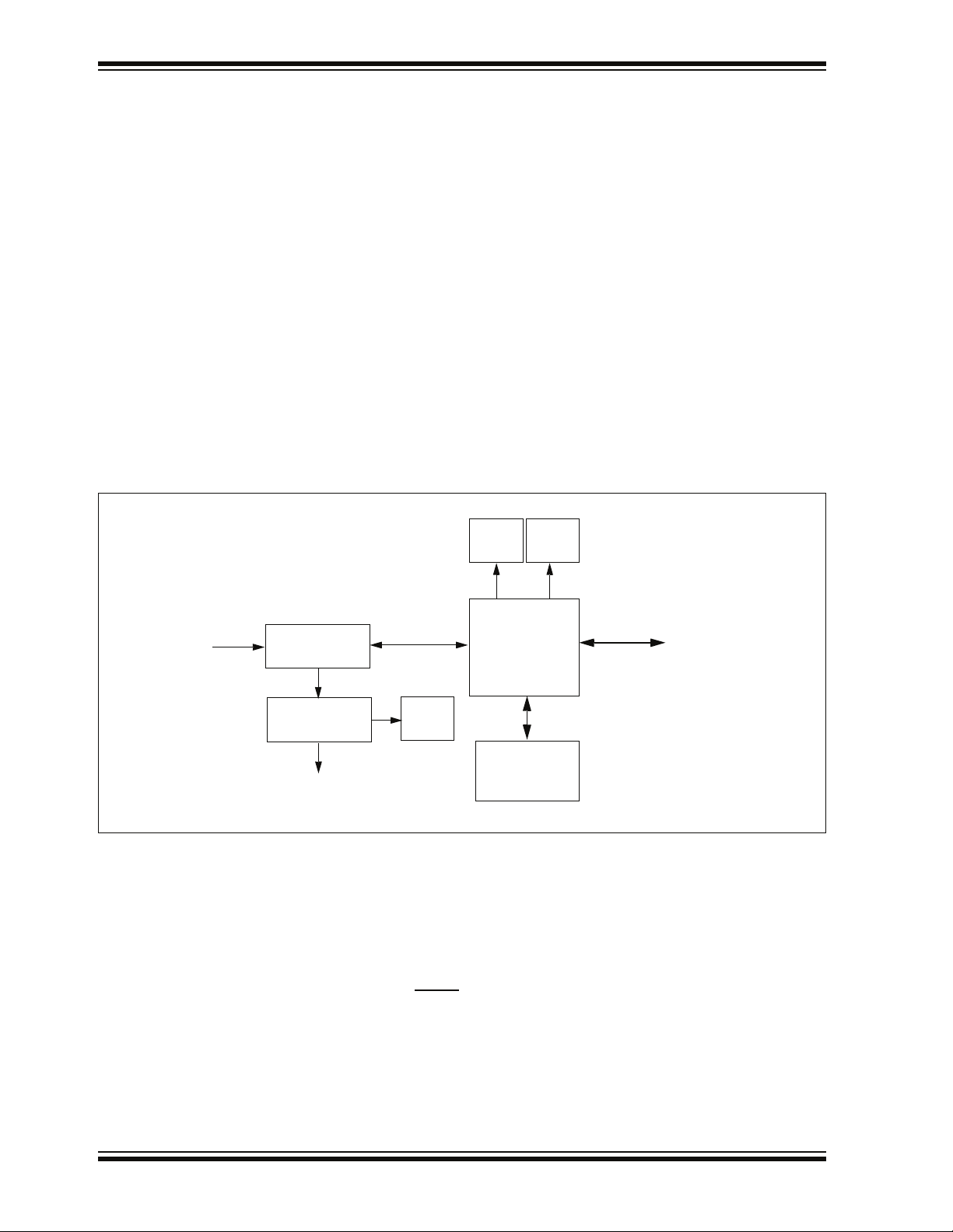
5.1 APPLICATION FUNCTIONAL OVERVIEW
Figure 5-1 illustrates the main functions of the starter kit:
FIGURE 5-1: APPLICATION SIDE BLOCK DIAGRAM
PIC24FJ256GB106
USER’S GUIDE
To Debugger Side
(PIC18F67J50)
Potentiometer
Keypads
The application side of the starter kit is centered on the PIC24F256GB106
microcontroller, which requires very little additional hardware to perform its tasks. All
application code is stored in the device’s Flash program memory. In addition to the
application core, the preloaded demo uses substantial parts of the Microchip USB
Stack Library, the Microchip Memory Disk Drive File System and the Microchip
Graphics Library to function.
The application accepts user inputs from the capacitive touch pad (S1) and the
potentiometer (R44). The microcontroller uses one of its A/D converter channels to
sample and convert the potentiometer’s value to a digital value for the Data Graphing
and Data Capture demos. Five additional A/D channels are used to monitor the
individual touch pads of S1. The values from these channels are analyzed with the
CTMU to determine when a touch-and-release event occurs on any of the pads. The
application firmware determines which action to take based on the application’s current
context.
Touch
32 kHz
Crystal
ICSP™
PMD7:PMD0
PGC/EMUC
PGD/EMUD
MCLR
AN0
AN8:AN12
SOSCI:SOSCO
PMRD
PMWR
PMCS1
PMA0
RG6/RG7
RG8/RG9
RF4/RF5
D+/D-
OLED
Display
Tri-Color
LED
USB
A Receptacle
USB mini-B
Receptacle
© 2008 Microchip Technology Inc. DS51725A-page 27
Page 32
MPLAB Starter Kit for PIC24F User’s Guide
The microcontroller directly drives the OLED display (LED1) and the tri-color LED (D6,
D10 or D11, depending on the board’s manufacturing option). The microcontroller uses
the Parallel Master Port to drive the OLED through the PMD7:PMD0 data lines, while
PMA0, PMCS2, PMRD and PMWR serve as control signals. A DC boost circuit
comprised of power MOSFET Q4, along with D5 and L3, provides the operating voltage
for the OLED.
The individual channels of the tri-color LED are driven directly by three of the
microcontroller’s PWM modules, assigned to outputs on pins RF4/RF5, RG6/RG7 and
RG8/RG9. Two output pins are used for each PWM to ensure sufficient drive strength
for each LED component.
The microcontroller uses an on-chip USB On-The-Go (OTG) engine and transceiver to
communicate with USB A and mini-B receptacles on the application side. While both
receptacles are populated, only the A receptacle is used in this version of the demo
application. The mini-B receptacle is available for users who may wish to design a
peripheral application.
5.2 PROGRAMMER/DEBUGGER FUNCTIONAL OVERVIEW
Figure 5-2 illustrates the debugging/programming operation of the starter kit.
FIGURE 5-2: STARTER KIT PROGRAMMER/DEBUGGER BLOCK DIAGRAM
From Host PC
USB mini-B
Jack
BUS
V
3.3V LDO
Regulator
VDD to Starter Kit
Debug
LED
USB Data
Power
LED
Serial EEPROM
12 MHz
Crystal
PIC18F67J50
SPI
25LC010A
ICSP™
To Application Side
(PIC24FJ256GB106)
In its default configuration, the Starter Kit functions as a USB bus-powered device.
Power is provided via the USB cable; the nominal 5 volt unregulated supply is regulated
by a Microchip MC1727 3.3 volt low-dropout (LDO) linear regulator. Proper main
system power is indicated by the green LED (D2).
The debugging and programming side of the Starter Kit is controlled by a PIC18F67J50
microcontroller running at 48 MHz. The PIC18F67J50’s built-in USB engine provides
the communications interface between the Starter Kit and the host PC. The
microcontroller manages debugging or programming of the target PIC24FJ256GB106
by controlling the target’s MCLR
power is switched on and off via a low V
, PGC1/EMUC1, and PGD1/EMUD1 signals. Target
CE saturation PNP transistor (Q1) configured
as a high-side switch. Target clocking is also provided by the PIC18F67J50.
A Microchip 25LC010A serial EEPROM is used to store the starter kit’s serial number
and debug control information.
DS51725A-page 28 © 2008 Microchip Technology Inc.
Page 33

5.3 BOARD COMPONENTS
Figure 5-3 identifies the key hardware components for the starter kit.
FIGURE 5-3: PIC24F STARTER KIT COMPONENT LAYOUT
Hardware
D3 D4
D5
A2
A1
A5
A6
D1
D2
A4
D8
A3
D9
D10
M
D7
D6
A9
TABLE 5-1: PIC24F STARTER KIT COMPONENT DESCRIPTIONS
Ref Debug/Programmer Component Ref Application Component
D1 mini-B USB Receptacle (J1) A1 PIC24F256GB106 Microcontroller (U6)
D2 PIC18F67J50 Microcontroller (U2) A2 Tri-Color LED Pads (D6, D10 or D11)
D3 MCP1727 Voltage Regulator (U1) A3 OLED Display (LED1)
D4 Target Power LED (D4) A4 Capacitive Touch Pad (S1)
D5 Low V
D6 Debugger/Programmer Clock Crystal (Y1) A6 USB A (Embedded Host) Receptacle (J4)
D7 25LC010A Serial EEPROM (U3) A7 mini-B USB (Peripheral) Receptacle (J5)
D8 V
D9 System Power LED (D2) A9 OLED Voltage Boost Cicuitry
D10 Debug LED (D3)
CE Saturation PNP Transistor Switch (Q1) A5 32.768 kHz (RTCC) Crystal (Y2)
BUS and GND Test Points A8 Potentiometer (R44)
A7
A8
5.3.1 Programmer/Debugger Components
The components listed here (in order of their reference tags in Figure 5-3) are the key
components of the programmer/debugger side of the starter kit:
D1. mini-B USB Receptacle (J1): Provides system power and bidirectional
communication between the host PC and starter kit.
D2. PIC18F67J50 Microcontroller (U2): Controls the programming/debugging
operations of the target PIC24FJ256GB106 microcontroller. It also provides the
12 MHz clock for the PIC24F microcontroller.
D3. MCP1727 Voltage Regulator (U1): The 3.3V linear regulator regulates the USB
unregulated voltage to 3.3 volts (with respect to V
with system power.
D4. Target Power LED (D4): When lit, indicates that power is being supplied to the
application side of the starter kit from V
the V
BUS test point).
© 2008 Microchip Technology Inc. DS51725A-page 29
BUS (either from a USB connection or from
SS) and supplies the starter kit
Page 34

MPLAB Starter Kit for PIC24F User’s Guide
D5. Low VCE Saturation PNP Transistor Switch (Q1): Provides target power (via
high-side switching) to the application side components via control by the
PIC18F67J50.
D6. Debugger/Programmer Clock Crystal (Y1): Provides an accurate 12 MHz
frequency reference for the PIC18F67J50 microcontroller for stable USB
operations in Programming and Debugging modes. The PIC18F67J50 also uses
this to generate a second 12 MHz clock for use by the PIC24FJ256GB106
microcontroller.
D7. 25LC010A Serial EEPROM (U3): Provides nonvolatile parameter storage for
the PIC18F67J50.
D8. V
BUS and GND Test Points: These unpopulated pads may be equipped with
appropriate connectors and furnished with power to operate the board in
Stand-Alone mode.
D9. System Power LED (D2): When lit, indicates that the starter kit is powered via
the USB.
D10. Debug LED (D3): When lit, indicates that communication between the starter
kit and MPLAB IDE has been successfully established.
5.3.2 Application Components
The components listed here (in order of their reference tags in Figure 5-3) are the key
components of the application side of the starter kit:
A1. PIC24F256GB106 Microcontroller (U6): This provides the processing power
for the demo applications and application development on the starter kit.
The microcontroller features 256 Kbytes of Flash program memory and
16 Kbytes RAM.
The demo application uses an external 12 MHz signal from the programmer side
as clock source. Custom applications that do not use the USB module may also
use the microcontroller’s on-chip FRC oscillator as a clock source. (USB applications must use the 12 MHz programmer clock source, as the tolerance of the
FRC oscillator exceeds USB specifications.)
A2. Tri-Color LED Pads (D6, D10 or D11): One of these locations is populated with
a three-channel (RGB) LED; the choice of the populated site depends on the
availability of components at the time of the board’s assembly. Functionally, the
LEDs at any of these sites are interchangeable.
A3. OLED Display (LED1): A 128 x 64 pixel, monochrome organic LED array
provides a wide range of graphics and alphanumeric display options.
A4. Capacitive Touch Pad (S1): This 5-element keypad is an integral part of the
board’s top layer. The application responds to capacitive changes induced by
direct contact with the user by monitoring each of the touch pad’s elements with
the microcontroller’s integrated CTMU module.
A5. RTCC Crystal (Y2): Provides an accurate 32.768 kHz reference for the micro-
controller’s secondary oscillator. This is used in turn as the time base for the
on-chip Real-Time Clock (RTC).
A6. USB A Receptacle (J4): The application uses this receptacle to connect with
USB peripherals while operating as an embedded host.
A7. Mini-B USB Receptacle (J5): Physically identical to J1, this provides USB con-
nectivity for the application side when it is functioning as a peripheral device.
A8. Potentiometer (R44): Provides an analog input to the microcontroller for certain
demo applications.
A9. OLED Voltage Boost Circuitry: L3, D5 and Q4 (along with other passive
components) are connected in a voltage boost topology. This provides the OLED
display with its nominal operating voltage of 13 V
DC.
DS51725A-page 30 © 2008 Microchip Technology Inc.
Page 35

MPLAB STARTER KIT FOR PIC24F
USER’S GUIDE
Appendix A. Starter Kit Schematics
The following schematic diagrams are included in this appendix:
Programmer/Debugger:
• Figure A-1: Programmer/Debugger Control System and EEPROM
• Figure A-2: Programmer/Debugger USB Interface, Target Power Switching and
Regulation
Application:
• Figure A-3: Application Microcontroller, Touch Switches and Associated
Components
• Figure A-4: OLED Display, LED and Application Side USB Connectors
© 2008 Microchip Technology Inc. DS51725A-page 31
Page 36

MPLAB Starter Kit for PIC24F User’s Guide
FIGURE A-1: STARTER KIT SCHEMATIC, SHEET 1: PROGRAMMER/DEBUGGER CONTROL
SYSTEM AND EEPROM
Serial EEPROM
Debug
DS51725A-page 32 © 2008 Microchip Technology Inc.
Page 37

Starter Kit Schematics
FIGURE A-2: STARTER KIT SCHEMATIC, SHEET 2: PROGRAMMER/DEBUGGER USB
INTERFACE, TARGET POWER SWITCHING AND REGULATION
Host MCU Switchable
Host MCU Switchable
VBUS Unregulated Supply
Target Power Indicator (VBUS)
3.3 V Regulated Supply
Status LED -
System Power
3.3 V LDO
Linear Regulator
USB Interface
(Bus Powered)
© 2008 Microchip Technology Inc. DS51725A-page 33
Page 38

MPLAB Starter Kit for PIC24F User’s Guide
FIGURE A-3: STARTER KIT SCHEMATIC, SHEET 3: APPLICATION MICROCONTROLLER,
TOUCH SWITCHES AND ASSOCIATED COMPONENTS
Data Logging
DS51725A-page 34 © 2008 Microchip Technology Inc.
Page 39

Starter Kit Schematics
FIGURE A-4: STARTER KIT SCHEMATIC, SHEET 4: OLED DISPLAY, LED AND
APPLICATION SIDE USB CONNECTORS
*
RGB LED
*
* Manufacturing option
(128 x 64)
Organic LED Display
© 2008 Microchip Technology Inc. DS51725A-page 35
Page 40

MPLAB Starter Kit for PIC24F User’s Guide
NOTES:
DS51725A-page 36 © 2008 Microchip Technology Inc.
Page 41

MPLAB STARTER KIT FOR PIC24F
USER’S GUIDE
Index
B
Block Diagrams
Starter Kit
Application Side......................................... 27
Programmer/Debugger Side...................... 28
Board Components
Capacitive Touch Pad....................................... 30
Debug LED ....................................................... 30
Debugger/Programmer Clock Crystal............... 30
mini-B USB Connector.................................29
OLED Display ................................................... 30
OLED Voltage Boost Circuitry .......................... 30
PIC18F67J50.................................................... 29
PIC24F256GB110 Microcontroller.................... 30
PNP Transistor Switch...................................... 30
Potentiometer ................................................... 30
RTCC Crystal.................................................... 30
Serial EEPROM ................................................ 30
Target Power LED ............................................ 29
Tri-Color LED.................................................... 30
USB A Receptacle ............................................ 30
BUS and GND Test Points..........................30, 29
V
Breakpoints .............................................................. 21
, 30
C
Charge Time Measurement Unit (CTMU) ................ 10
Configuration Bits..................................................... 25
Customer Notification Service.................................... 4
Customer Support...................................................... 5
D
Debug ........................................................................ 7
Executive .......................................................... 20
Reserved Resources ........................................ 24
Setup ................................................................ 20
Demonstration Applications ....................................... 9
Interactive Display System ................................. 9
Other Interactive Demos................................... 13
Real-Time Data Capture................................... 13
Real-Time Data Graphing................................. 12
RGB LED Control ............................................. 11
Time and Date .................................................. 11
Touch Interface................................................. 10
Calibration ................................................. 10
USB Flash Drive Interface ................................ 12
Device, Debug Mode ............................................... 15
Device, Release Mode............................................. 16
Documentation
Conventions........................................................ 2
Layout ................................................................. 1
E
Embedded Host, Debug Mode................................. 15
Embedded Host, Release Mode .............................. 17
H
Halt........................................................................... 21
Host Computer Requirements.................................... 7
I
Initial Board Setup...................................................... 8
Internet Address......................................................... 4
M
Microchip Internet Web Site ....................................... 4
MPLAB IDE .......................................................... 7
, 19
P
Power Options.......................................................... 15
Programmer ............................................................. 24
R
Reading, Recommended ........................................... 3
Real-Time Clock and Calendar (RTCC)................... 11
Reserved Resources................................................ 24
Reset........................................................................ 21
Run........................................................................... 21
S
Schematic Diagrams................................................ 31
Stand-Alone Mode ................................................... 17
Starter Kit
Board Components........................................... 29
Step.......................................................................... 21
T
Troubleshooting ....................................................... 25
U
Unable to Enter Debug Mode................................... 25
W
Warranty Registration ................................................ 2
Watch Window ......................................................... 21
WWW Address........................................................... 4
© 2008 Microchip Technology Inc. DS51725A-page 37
Page 42

WORLDWIDE SALES AND SERVICE
AMERICAS
Corporate Office
2355 West Chandler Blvd.
Chandler, AZ 85224-6199
Tel: 480-792-7200
Fax: 480-792-7277
Technical Support:
http://support.microchip.com
Web Address:
www.microchip.com
Atlanta
Duluth, GA
Tel: 678-957-9614
Fax: 678-957-1455
Boston
Westborough, MA
Tel: 774-760-0087
Fax: 774-760-0088
Chicago
Itasca, IL
Tel: 630-285-0071
Fax: 630-285-0075
Dallas
Addison, TX
Tel: 972-818-7423
Fax: 972-818-2924
Detroit
Farmington Hills, MI
Tel: 248-538-2250
Fax: 248-538-2260
Kokomo
Kokomo, IN
Tel: 765-864-8360
Fax: 765-864-8387
Los Angeles
Mission Viejo, CA
Tel: 949-462-9523
Fax: 949-462-9608
Santa Clara
Santa Clara, CA
Tel: 408-961-6444
Fax: 408-961-6445
Toronto
Mississauga, Ontario,
Canada
Tel: 905-673-0699
Fax: 905-673-6509
ASIA/PACIFIC
Asia Pacific Office
Suites 3707-14, 37th Floor
Tower 6, The Gateway
Harbour City, Kowloon
Hong Kong
Tel: 852-2401-1200
Fax: 852-2401-3431
Australia - Sydney
Tel: 61-2-9868-6733
Fax: 61-2-9868-6755
China - Beijing
Tel: 86-10-8528-2100
Fax: 86-10-8528-2104
China - Chengdu
Tel: 86-28-8665-5511
Fax: 86-28-8665-7889
China - Hong Kong SAR
Tel: 852-2401-1200
Fax: 852-2401-3431
China - Nanjing
Tel: 86-25-8473-2460
Fax: 86-25-8473-2470
China - Qingdao
Tel: 86-532-8502-7355
Fax: 86-532-8502-7205
China - Shanghai
Tel: 86-21-5407-5533
Fax: 86-21-5407-5066
China - Shenyang
Tel: 86-24-2334-2829
Fax: 86-24-2334-2393
China - Shenzhen
Tel: 86-755-8203-2660
Fax: 86-755-8203-1760
China - Wuhan
Tel: 86-27-5980-5300
Fax: 86-27-5980-5118
China - Xiamen
Tel: 86-592-2388138
Fax: 86-592-2388130
China - Xian
Tel: 86-29-8833-7252
Fax: 86-29-8833-7256
China - Zhuhai
Tel: 86-756-3210040
Fax: 86-756-3210049
ASIA/PACIFIC
India - Bangalore
Tel: 91-80-4182-8400
Fax: 91-80-4182-8422
India - New Delhi
Tel: 91-11-4160-8631
Fax: 91-11-4160-8632
India - Pune
Tel: 91-20-2566-1512
Fax: 91-20-2566-1513
Japan - Yokohama
Tel: 81-45-471- 6166
Fax: 81-45-471-6122
Korea - Daegu
Tel: 82-53-744-4301
Fax: 82-53-744-4302
Korea - Seoul
Tel: 82-2-554-7200
Fax: 82-2-558-5932 or
82-2-558-5934
Malaysia - Kuala Lumpur
Tel: 60-3-6201-9857
Fax: 60-3-6201-9859
Malaysia - Penang
Tel: 60-4-227-8870
Fax: 60-4-227-4068
Philippines - Manila
Tel: 63-2-634-9065
Fax: 63-2-634-9069
Singapore
Tel: 65-6334-8870
Fax: 65-6334-8850
Taiwan - Hsin Chu
Tel: 886-3-572-9526
Fax: 886-3-572-6459
Taiwan - Kaohsiung
Tel: 886-7-536-4818
Fax: 886-7-536-4803
Taiwan - Taipei
Tel: 886-2-2500-6610
Fax: 886-2-2508-0102
Thailand - Bangkok
Tel: 66-2-694-1351
Fax: 66-2-694-1350
EUROPE
Austria - Wels
Tel: 43-7242-2244-39
Fax: 43-7242-2244-393
Denmark - Copenhagen
Tel: 45-4450-2828
Fax: 45-4485-2829
France - Paris
Tel: 33-1-69-53-63-20
Fax: 33-1-69-30-90-79
Germany - Munich
Tel: 49-89-627-144-0
Fax: 49-89-627-144-44
Italy - Milan
Tel: 39-0331-742611
Fax: 39-0331-466781
Netherlands - Drunen
Tel: 31-416-690399
Fax: 31-416-690340
Spain - Madrid
Tel: 34-91-708-08-90
Fax: 34-91-708-08-91
UK - Wokingham
Tel: 44-118-921-5869
Fax: 44-118-921-5820
01/02/08
DS51725A-page 38 © 2008 Microchip Technology Inc.
 Loading...