

Page 1

MCP3905/06
Energy-Metering ICs with Acti ve (Real) Power Pulse Output
Features
• Supplies ac tive (real) power measurement for
single-phase, residential energy-metering
• Supports the IEC 62053 International Energy
Metering Specification and legacy IEC
1036/61036/687 Specifications
• Two multi-bit, Digital-to-Analog Converters
(DACs), second-order, 16-bit, Delta-Sigma
Analog-to-Digital Converters (ADCs)
• 0.1% typical measurement error over 500:1
dynamic range (MCP3905)
• 0.1% typical measurement error over 1000:1
dynamic range (MCP3906)
• Programmable Gain Amplifier (PGA) for smallsignal inputs supports low-value shunt current
sensor
- 16:1 PGA - MCP3905
- 32:1 PGA - MCP3906
• Ultra-low drift on-chip reference: 15 ppm/°C (typ.)
• Direct drive for electromagnetic mechanical
counter and two-phase stepper motors
•Low I
• Tamper output pin for negative power indication
• Industrial Temperature Range: -40°C to +85°C
• Supplies instantaneous active (real) power on
HF
US Patents Pending
of 4 mA (typ.)
DD
for meter calibration
OUT
Description
The MCP3905/06 devices are energy-metering ICs
designed to support the IEC 62053 International
Metering Standard Specification. They supply a
frequency output proportional to the average active
(real) power, as well as a higher-frequency output
proportional to the instantaneous power for meter
calibration. They include two 16-bit, delta-sigma ADCs
for a wide r ange of I
and I
B
currents and/or small
MAX
shunt (< 200 µOhms) meter designs. It includes an
ultra-low drift voltage reference with < 15 ppm/°C
through a specially designed band gap temperature
curve for the minimum gradient across the industrial
temperature range. A fixed-function DSP block is onchip for active (real) power calculation. Strong output
drive for mechanical counters are on-chip to reduce
field failures and mechanical counter sticking. A noload threshold block prevents any current creep measurements. A Power-On Reset (POR) block restricts
meter performance during low-voltage situations.
These accurate energy-metering ICs with high field
reliability are available in the ind us try-s t a nda rd pino ut.
Package Type
24-Pin SSOP
DV
DD
HPF
AV
DD
NC
CH0+
CH0CH1-
CH1+
MCLR
REFIN/OUT
A
GND
F2
1
2
3
4
5
6
7
8
10
11
F
24
F
23
22
HF
D
21
NEG
20
NC
19
18
OSC2
17
OSC1
169G0
15
G1
14
F0
1312F1
OUT0
OUT1
OUT
GND
Functional Block Diagram
G0 G1
CH0+
CH0-
REFIN/
OUT
CH1+
CH1-
© 2007 Microchip Technology Inc. DS21948D-page 1
+
–
2.4V
Reference
+
–
PGA
16-bit
Multi-level
ΔΣ ADC
16-bit
Multi-level
ΔΣ ADC
HPF
HPF1
HPF1
OSC1 OSC2
X
LPF1
POR
F2 F1
HF
F0
E-to-F
conversion
OUT
F
OUT1
MCLR
F
OUT0
NEG
Page 2
MCP3905/06
1.0 ELECTRICAL CHARACTERISTICS
Absolute Maximum Ratings †
VDD...................................................................................7.0V
Digital inputs and outputs w.r.t. A
Analog input w.r.t. A
input w.r.t. A
V
REF
Storage temperature.. .. .. .. .. ....... .. .. .. .. .... .. ..... .-65°C to +150°C
Ambient temp. with power applied................ -65°C to +125°C
Soldering temperature of leads (10 seconds) .............+300°C
ESD on the analog inputs (HBM,MM)... ......... .... .5.0 kV, 500V
ESD on all other pins (HBM,MM)........................5.0 kV, 500V
.........................................-6V to +6V
GND
...............................-0.6V to VDD +0.6V
GND
........-0.6V to VDD +0.6V
GND
† Notice: Stresses above those listed under "Maximum
Ratings" may cause permanent damage to the device. This is
a stress rating only and functional operation of the device at
those or any other conditions above those indicated in the
operation listings of this specification is not implied. Exposure
to maximum rating conditions for extended periods may affect
device reliability.
ELECTRICAL CHARACTERISTICS
Electrical Specifications: Unless otherwise indicated, all parameters apply at AV
Internal V
, HPF turned on (AC mode), A
REF
GND
, D
= 0V, MCLK = 3.58 MHz; TA = -40°C to +85°C.
GND
Parameter Sym Min Typ. Max Units Comment
Overall Measurement Accuracy
Energy Measurement Error E — 0.1 — % F
— 0.1 — % F
No-Load Threshold/
NLT — 0.0015 — % F
Minimum Load
Phase Delay Between
— — 1/MCLK s HPF = 0 and 1, < 1 MCLK
OUT
OUT
OUT
Max
Channels
AC Power Supply
AC PSRR — 0.01 — % F
OUT
Rejection Ratio
(Output Frequency Variation)
DC Power Supply
DC PSRR — 0.01 — % F
OUT
Rejection Ratio
(Output Frequency Variation)
System Gain Error — 3 10 % F
OUT
ADC/PGA Specifications
Offset Error V
OS
Gain Error Match — 0.5 — % F
— 2 5 mV Referred to Input
OUT
Internal Voltage Reference
Voltage — 2.4 — V
Tolerance — ±2 — %
Tempco — 15 — ppm/°C
Note 1: Measurement error = (Energy Measured By Device - True Energy)/True Energy * 100%. Accuracy is
, F
measured with signal (±660 mV) on Channel 1. F
OUT0
pulse outputs. Valid from 45 Hz to 65 Hz.
OUT1
See Section 2.0 “Typical Performance Curves” for higher frequencies and increased dynamic range.
2: Does not include internal V
. Gain = 1, CH0 = 470 mVDC, CH1 = 660 mVDC, difference between
REF
measured output frequency and expected transfer function.
3: Percent of HF
50 Hz, CH2 = 100 mVRMS @ 50 Hz, AV
output frequency variation; Includes external V
OUT
= 5V + 1Vpp @ 100 Hz. DC PSRR: 5V ±500 mV.
DD
REF
4: Error applies down to 60° lead (PF = 0.5 capacitive) and 60° lag (PF = 0.5 inductive).
5: Refer to Section 4.0 “Device Overview” for complete description.
6: Specified by characterization, not production tested.
7: 1 MCLK period at 3.58 MHz is equivalent to less than <0.005 degrees at 50 or 60 Hz.
8: Gain error match is measured from CH0 G = 1 to any other gain setting.
= DVDD = 4.5V – 5.5V,
DD
Channel 0 swings 1:500 range,
MCP3905 only (Note 1, Note 4)
Channel 0 swings 1:1000 range,
MCP3906 only (Note 1, Note 4)
Disabled when F2, F1, F0 = 0, 1, 1
(Note 5, Note 6)
(Note 4, Note 6, Note 7)
F2, F1, F0 = 0, 1, 1 (Note 3)
HPF = 1, Gain = 1 (Note 3)
Note 2, Note 5
Note 8
= 2.5V, CH1 = 100 mVRMS @
DS21948D-page 2 © 2007 Microchip Technology Inc.
Page 3

MCP3905/06
ELECTRICAL CHARACTERISTICS (CONTINUED)
Electrical Specifications: Unless otherwise indicated, all parameters apply at AV
Internal V
, HPF turned on (AC mode), A
REF
GND
, D
= 0V, MCLK = 3.58 MHz; TA = -40°C to +85°C.
GND
Parameter Sym Min Typ. Max Units Comment
Reference Input
Input Range 2.2 — 2.6 V
Input Impedance 3.2 — — kΩ
Input Capacitance — — 10 pF
Analog Inputs
Maximum Signal Level — — ±1 V CH0+,CH0-,CH1+,CH1- to A
Differential Input Voltage
— — ±470/G mV G = PGA Gain on Channel 0
Range Channel 0
Differential Input Voltage
——±660mV
Range Channel 1
Input Impedance 390 — — kΩ Proportional to 1/MCLK frequency
Bandwidth
— 14 — kHz Proportional to MCLK frequency,
(Notch Frequency)
Oscillator Input
Frequency Range MCLK 1 — 4 MHz
Power Specifications
Operating Voltage 4.5 — 5.5 V AV
I
DD,A
I
DD,D
I
DD,A
I
DD,D
—2.7 3.0 mAAV
—1.2 2.0 mADV
Note 1: Measurement error = (Energy Measured By Device - True Energy)/True Energy * 100%. Accuracy is
measured with signal (±660 mV) on Channel 1. F
OUT0
, F
pulse outputs. Valid from 45 Hz to 65 Hz.
OUT1
See Section 2.0 “Typical Performance Curves” for higher frequencies and increased dynamic range.
2: Does not include internal V
. Gain = 1, CH0 = 470 mVDC, CH1 = 660 mVDC, difference between
REF
measured output frequency and expected transfer function.
3: Percent of HF
50 Hz, CH2 = 100 mVRMS @ 50 Hz, AV
output frequency variation; Includes external V
OUT
= 5V + 1Vpp @ 100 Hz. DC PSRR: 5V ±500 mV.
DD
REF
4: Error applies down to 60° lead (PF = 0.5 capacitive) and 60° lag (PF = 0.5 inductive).
5: Refer to Section 4.0 “Device Overview” for complete description.
6: Specified by characterization, not production tested.
7: 1 MCLK period at 3.58 MHz is equivalent to less than <0.005 degrees at 50 or 60 Hz.
8: Gain error match is measured from CH0 G = 1 to any other gain setting.
= DVDD = 4.5V – 5.5V,
DD
MCLK/256
DD, DVDD
pin only
DD
pin only
DD
= 2.5V, CH1 = 100 mVRMS @
GND
TEMPERATURE CHAR ACTERISTICS
Electrical Specifications: Unless otherwise indicated, V
= 4.5V – 5.5V, A
DD
Parameters Sym Min Typ Max Units Conditions
Temperature Ranges
Specified Temperature Range T
Operating Temperature Range T
Storage Temperature Range T
-40 — +85 °C
A
-40 — +125 °C Note
A
-65 — +150 °C
A
Note: The MCP3905/06 operate over this extended temperature range, but with reduced performance. In any
case, the Junction Temperature (T
© 2007 Microchip Technology Inc. DS21948D-page 3
) must not exceed the Absolute Maximum specification of +150°C.
J
GND
, D
GND
= 0V.
Page 4

MCP3905/06
TIMING CHARACTERISTICS
Electrical Specifications: Unless otherwise indicated, all parameters apply at AV
A
, D
GND
= 0V, MCLK = 3.58 MHz; TA = -40°C to +85°C.
GND
Parameter Sym Min Typ Max Units Comment
Frequency Output
F
OUT0
and F
Pulse Width
OUT1
t
FW
— 275 — ms 984376 MCLK periods
(Logic-Low)
Pulse Width t
HF
OUT
and F
F
OUT0
Pulse Period t
HF
OUT
F
to F
OUT0
F
to F
OUT0
F
and F
OUT0
F
and F
OUT0
HF
Output High Voltage V
OUT
Output Low Voltage V
HF
OUT
Pulse Period t
OUT1
Falling-Edge Ti me t
OUT1
Min Separation t
OUT1
Output High Voltage V
OUT1
Output Low Voltage V
OUT1
High-Level Input Voltage
HW
HP
FS2
V
FP
FS
OH
OL
OH
OL
IH
— 90 — ms 322160 MCLK periods
Refer to Equation 4-1 s
Refer to Equation 4-2 s
— 0.5 t
— 4/MCLK —
FP
—
4.5 ——VIOH = 10 mA, DVDD = 5.0V
——0.5 V I
4.0 ——VIOH = 5 mA, DVDD = 5.0V
——0.5 V I
2.4 ——VDVDD = 5.0V
(All Digital Input Pins)
Low-Level Input Voltage
V
IL
——0.85 V DV
(All Digital Input Pins)
Input Leakage Current
——±3 µA V
Pin Capacitance ——10 pF Note 3
Note 1: If output pulse period (tFP) falls below 984376*2 MCLK periods, then tFW = 1/2 tFP.
2: If output pulse period (tHP) falls below 322160*2 MCLK periods, then tHW = 1/2 tHP.
3: Specified by characterization, not production tested.
= DVDD = 4.5V – 5.5V,
DD
(Note 1)
(Note 2)
= 10 mA, DVDD = 5.0V
OL
= 5 mA, DVDD = 5.0V
OL
DD
= 0, VIN = DV
IN
= 5.0V
DD
t
FP
t
FW
F
OUT0
t
FS
F
HF
OUT1
OUT
t
HW
t
HP
t
FS2
NEG
FIGURE 1-1: Output Timings for Pulse Outputs and Negative Power Pin.
DS21948D-page 4 © 2007 Microchip Technology Inc.
Page 5
MCP3905/06
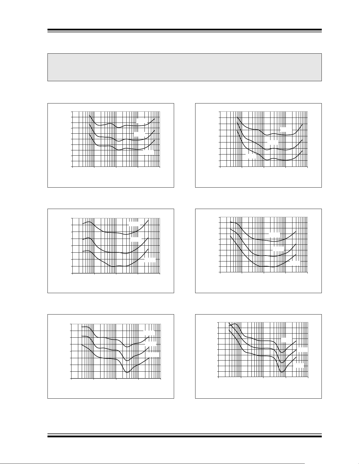
2.0 TYPICAL PERFORMANCE CURVES
Note: The graphs and tables provided fol low i ng thi s n ote are a statistical summ ar y b as ed on a limited num ber of
samples and are provided for informational purposes only. The performance characteristics listed herein
are not tested or guaranteed. In some graphs or tables, the data presented may be outside the specified
operating range (e.g., outside specified power supply range) and therefore outside the warranted range.
Note: Unless otherwise specified, DVDD, AVDD = 5V; A
MCLK = 3.58 MHz.
0.5
0.4
0.3
0.2
0.1
0
-0.1
-0.2
-0.3
Measure ment Error
-0.4
-0.5
0.0000 0.0001 0.0010 0.0100 0.1000
CH1 Vp-p Amplitude (V)
+85°C
+25°C
-40°C
FIGURE 2-1: Measurement Error,
Gain = 8, PF = 1.
0.5
0.4
0.3
0.2
0.1
0
-0.1
Measurement Error
-0.2
-0.3
0.0000 0.0001 0.0010 0.0100 0.1000
CH1 Vp-p Amplitude (V)
+85°C
+25°C
- 40°C
GND
, D
GND
= 0V; V
-0.1
Measurement Error
-0.2
-0.3
= Internal, HPF = 1 (AC mode),
REF
0.6
0.5
0.4
0.3
0.2
0.1
0
-40°C
0.0000 0.0001 0.0010 0.0100 0.1000
CH1 Vp-p Amplitude (V)
+25°C
FIGURE 2-4: Measurement Error,
Gain = 8, PF = 0.5.
0.7
0.6
0.5
0.4
0.3
0.2
0.1
0
-0.1
Measurement Error
-0.2
-0.3
0.0000 0.0001 0.0010 0.0100 0.1000
CH1 Vp-p Amplitude (V)
+85°C
+25°C
+85°C
-40°C
FIGURE 2-2: Measurement Error,
Gain = 16, PF = 1.
0.8
0.6
0.4
0.2
0
-0.2
-0.4
Measurement Error
-0.6
-0.8
0.0000 0.0001 0.0010 0.0100 0.1000
CH1 Vp-p Amplitude (V)
+85°C
+25°C
FIGURE 2-3: Measurement Error,
Gain = 32, PF = 1.
- 40°C
FIGURE 2-5: Measurement Error,
Gain = 16, PF = 0.5.
1
0.8
0.6
0.4
0.2
0
-0.2
-0.4
-0.6
Measurement Error
-0.8
-1
0.0000 0.0001 0.0010 0.0100 0.1000
CH1 Vp-p Amplitude (V)
+85°C
-40°C
FIGURE 2-6: Measurement Error,
Gain = 32, PF = 0.5.
+25°C
© 2007 Microchip Technology Inc. DS21948D-page 5
Page 6
MCP3905/06
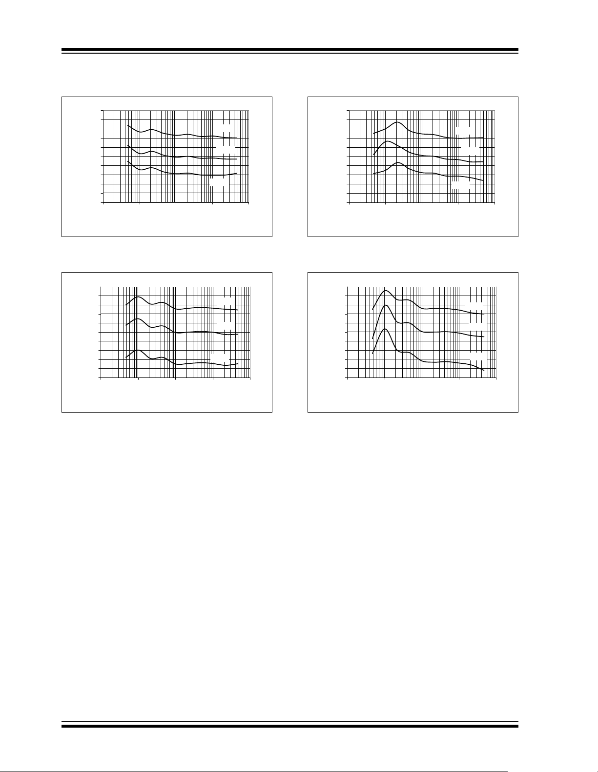
Note: Unless otherwise specified, DVDD, AVDD = 5V; A
MCLK = 3.58 MHz.
0.5
0.4
0.3
0.2
0.1
0
-0.1
-0.2
-0.3
Measure ment Error
-0.4
-0.5
0.0001 0.0010 0.0100 0.1000 1.0000
CH0 Vp-p Amplitude (V)
+85°C
+25°C
- 40°C
FIGURE 2-7: Measurement Error,
Gain = 1, PF = 1.
0.5
0.4
0.3
0.2
0.1
0
-0.1
-0.2
-0.3
Measurement Error
-0.4
-0.5
0.0001 0.0010 0.0100 0.1000 1.0000
CH0 Vp-p Amplitude (V)
+85°C
+25°C
- 40°C
GND
, D
GND
= 0V; V
-0.1
-0.2
-0.3
Measurement Error
-0.4
-0.5
= Internal, HPF = 1 (AC mode),
REF
0.5
0.4
0.3
0.2
0.1
0
0.0001 0.0010 0.0100 0.1000 1.0000
CH1 Vp-p Amplitude (V)
FIGURE 2-9: Measurement Error,
Gain = 1, PF = + 0.5.
0.5
0.4
0.3
0.2
0.1
0
-0.1
-0.2
-0.3
Measurement Error
-0.4
-0.5
0.0001 0.0010 0.0100 0.1000 1.0000
CH1 Vp-p Amplitude (V)
+85°C
+25°C
-40°C
+85°C
+25°C
-40°C
FIGURE 2-8: Measurement Error,
Gain = 2, PF = 1.
FIGURE 2-10: Measurement Error,
Gain = 2, PF = + 0.5.
DS21948D-page 6 © 2007 Microchip Technology Inc.
Page 7
MCP3905/06
Note: Unless otherwise specified, DVDD, AVDD = 5V; A
MCLK = 3.58 MHz.
0.5
0.4
0.3
0.2
0.1
0
-0.1
% Error
-0.2
-0.3
-0.4
-0.5
PF = 1.0
45 50 55 60 65 70 75
Frequency (Hz)
PF = 0.5
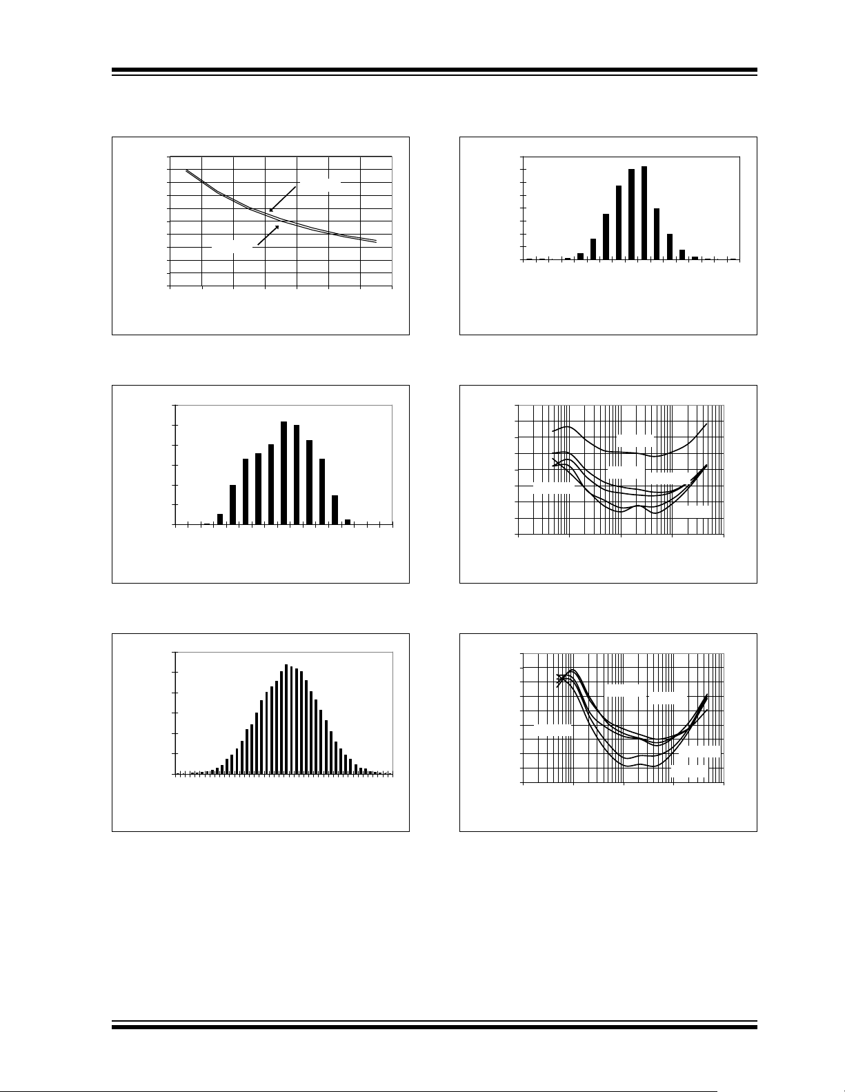
FIGURE 2-11: Measurement Error vs.
Input Frequency.
3000
16384 Samples
2500
Mean = -1.57 mV
Std. Dev = 52.5 µV
2000
1500
1000
Occurance
500
0
-1.75
-1.70
-1.65
-1.61
-1.56
-1.52
-1.47
-1.43
-1.38
Channel 0 Offset (mV)
GND
, D
GND
= 0V; V
4000
3500
3000
2500
2000
1500
Occurance
1000
= Internal, HPF = 1 (AC mode),
REF
16384 Samples
Mean = - 1.28 mV
Std. dev = - 18.1 µV
500
0
-1.38E-03
-1.37E-03
-1.36E-03
-1.35E-03
-1.34E-03
-1.33E-03
-1.32E-03
-1.31E-03
Bin (mV)
-1.30E-03
-1.29E-03
-1.28E-03
FIGURE 2-14: Channel 0 Offset Error
(DC Mode, HPF Off), G = 16.
0.3
0.2
0.1
0
-0.1
-0.2
VDD=5.25V
-0.3
Measurement Error
-0.4
-0.5
0.0001 0.0010 0.0100 0.1000 1.0000
CH0 Vp-p Amplitude (V)
VDD=5.0V
VDD=4.5V
VDD=4.75V
-1.27E-03
-1.26E-03
VDD=5.5V
-1.25E-03
-1.24E-03
-1.23E-03
-1.22E-03
FIGURE 2-12: Channel 0 Offset Error
(DC Mode, HPF off), G = 1.
1200
16384 Samples
1000
Mean = -1.64 mV
Std. Dev = 17.4 µV
800
600
400
Occurance
200
0
-1.71
-1.69
-1.68
-1.67
-1.66
-1.65
-1.64
-1.63
-1.62
-1.60
Channel 0 Offset (mV)
FIGURE 2-13: Channel 0 Offset Error
(DC Mode, HPF off), G = 8.
-1.59
FIGURE 2-15: Measurement Error vs. V
(G = 16).
0.3
0.25
0.2
0.15
0.1
0.05
VDD=5.0V
0
-0.05
Measurement Error
-0.1
-0.15
0.0001 0.0010 0.0100 0.1000 1.0000
VDD=4.75V
CH0 Vp-p Amplitude (V)
VDD=4.5V
VDD=5.25V
VDD=5.5V
FIGURE 2-16: Measurement Error vs. V
G = 16, External V
REF
.
DD
DD
,
© 2007 Microchip Technology Inc. DS21948D-page 7
Page 8

MCP3905/06
Note: Unless otherwise specified, DVDD, AVDD = 5V; A
MCLK = 3.58 MHz.
0.3
0.2
0.1
0
-0.1
Measurement Error
-0.2
-0.3
0.0001 0.0010 0.0100 0.1000 1.0000
CH0 Vp-p Amplitude (V)
+85°C
+25°C
- 40°C
FIGURE 2-17: Measurem ent Error
w/ External V
0.3
0.2
0.1
0
-0.1
Measurement Error
-0.2
-0.3
0.0000 0.0001 0.0010 0.0100 0.1000
, (G = 1).
REF
CH1 Vp-p Ampli tude (V)
+85°C
+25°C
-40°C
GND
, D
GND
= 0V; V
-0.1
Measurement Error
-0.2
-0.3
= Internal, HPF = 1 (AC mode),
REF
0.3
0.2
0.1
0
0.0000 0.0001 0.0010 0.0100 0.1000
CH1 Vp-p Amplitude (V)
FIGURE 2-19: Measurement Error
w/ External V
(G = 16).
REF
+85°C
- 40°C
+25°C
FIGURE 2-18: Measurement Error
w/ External V
, (G = 8).
REF
DS21948D-page 8 © 2007 Microchip Technology Inc.
Page 9

3.0 PIN DESCRIPTIONS
The descriptions of the pins are listed in Table 3 -1.
TABLE 3-1: PIN FUNCTION TABLE
Pin No. Symbol Function
MCP3905/06
1DV
2 HPF High-Pass Filters Control Logic Pin
3AV
4 NC No Connect
5 CH0+ Non-Inverting Analog Input Pin for Channel 0 (Current Channel)
6 CH0- Inverting Analog Input Pin for Channel 0 (Current Channel)
7 CH1- Inverting Analog Input Pin for Channel 1 (Voltage Channel)
8 CH1+ Non-Inverting Analog Input Pin for Channel 1 (Voltage Channel)
9MCLR
10 REFIN/OUT Voltage Reference Input/Output Pin
11 A
12 F2 Frequency Control for HF
13 F1 Frequency Control for F
14 F0 Frequency Control for F
15 G1 Gain Control Logic Input Pin
16 G0 Gain Control Logic Input Pin
17 OSC1 Oscillator Crystal Connection Pin or Clock Input Pin
18 OSC2 Oscillator Crystal Connection Pin or Clock Output Pin
19 NC No Connect
20 NEG Negative Power Logic Output Pin
21 D
22 HF
23 F
24 F
DD
DD
GND
GND
OUT
OUT1
OUT0
Digital Power Supply Pin
Analog Power Supply Pin
Master Clear Logic Input Pin
Analog Ground Pin, Return Path for internal analog circuitry
Logic Input Pin
OUT
Logic Input Pin
OUT0/1
Logic Input Pin
OUT0/1
Digital Ground Pin, Return Path for Internal Digital Circuitry
High-Frequency Logic Output Pin (Intended for Calibration)
Differential Mechanical Counter Logic Output Pin
Differential Mechanical Counter Logic Output Pin
3.1 Digital VDD (DVDD)
DVDD is the power supply pin for the digital circuitry
within the MCP3905/06.
requires appropriate bypass capacitors and
DV
DD
should be maintained to 5V ±10% for specified
operation. Please refer to Section 5.0 “Application s
Information”.
3.2 High-Pass Filter Input Logic Pin (HPF)
HPF controls the state of the high-pass filter in both
input channels. A logic ‘1’ enables both filters,
removing any DC offset coming from the system or the
device. A logic ‘0’ disables both filters, allowing DC
voltages to be measured.
© 2007 Microchip Technology Inc. DS21948D-page 9
3.3 Analog VDD (AVDD)
AVDD is the power supply pin for the analog circuitry
within the MCP3905/06.
requires appropriate bypass capacitors and
AV
DD
should be maintained to 5V ±10% for specified
operation. Please refer to Section 5.0 “Applications
Information”.
3.4 Current Channel (CH0-, CH0+)
CH0- and CH0+ are the ful ly dif fere ntial a nalog v olt age
input channels for the current me asurement, cont aining
a PGA for sma ll-signal input, such as shunt curre ntsensing. The linear and spe cified region of this channel
is dependant on the PGA gain. This corresponds to a
maximum differential voltage of ±470 mV/GAIN and
maximum absolute voltage, with respect to A
±1V. Up to ±6V can be applied to these pi ns without the
risk of permanent damage.
Refer to Section 1.0 “Electrical Characteristics”.
GND
, of
Page 10

MCP3905/06
3.5 Voltage Channel (CH1-,CH1+)
CH1- and CH1+ are the ful ly dif fere ntial a nalog volt age
input channels fo r the volt age meas urement. The linear
and specified region of these channels have a
maximum differential voltage of ±660mV and a
maximum absolute voltage of ±1V, with respect to
. Up to ±6V can be applied to these pins without
A
GND
the risk of permanent damage.
Refer to Section 1.0 “Electrical Characteristics”.
3.6 Master Clear (MCLR)
MCLR controls the reset for both del ta-sigma ADCs, al l
digital registers, the SINC filters for each channel and
all accumulators post multiplier. A logic ‘0’ resets all
registers and holds both ADCs in a Reset condition.
The charge stored in both ADCs is flushed and their
output is maintained to 0x0000h. The only block
consuming power on the digital power supply during
Reset is the oscillator circuit.
3.7 Reference (REFIN/OUT)
REFIN/OUT is the output for the internal 2.4V
reference. This reference has a typical temperature
coefficient of 15 ppm/°C and a tolerance of ±2%. In
addition, an external reference can also be used by
applying voltage to this pin within the specified range.
REFIN/OUT requires appropriate bypass capacitors to
, even when using the internal reference only.
A
GND
Refer to Section 5 .0 “Applications Information”.
3.8 Analog Ground (A
A
is the ground connection to the internal analog
GND
circuitry (ADCs, PGA, band gap reference, POR). To
ensure accuracy and noise cancellation, this pin must
be connected to the same ground as D
with a star connection. If an analog ground plane is
available, it is recommended that this device be tied to
this plane of the Printed Circuit Board (PCB). This
plane should a lso reference all other a nal og ci rcuitry in
the system.
GND
)
GND
, preferably
3.9 Frequency Control Logic Pins (F2, F1, F0)
F2, F1 and F0 select the high-frequency output and
low-frequency output pin ranges by changing the
value of the constants F
transfer function. F
constants that define the period of the output pulses
for the device.
and HFC used in the device
C
and H
C
are the frequency
FC
3.10 Gain Control Logic Pins (G1, G0)
G1 and G0 select the PGA gain on Channel 0 from
three different values: 1, 8 and 16.
3.11 Oscillator (OSC1, OSC2)
OSC1 and OSC2 provide the master clock for the
device. A resonant crystal or clock source with a similar
sinusoidal waveform must be placed across these pins
to ensure proper operati on. The typic al clock freque ncy
specified is 3.579545 MHz. However, the clock
frequency can be with the range of 1 MHz to 4 MHz
without disturbing measurement error. Appropriate
load capacit ance should b e conne cted to th ese pin s for
proper operation.
A full-swing, single-ended clock source may be
connected to OSC1 with proper resistors in series to
ensure no ringing of the clock source due to fast
transient edges.
3.12 Negative Power Output Logic Pin (NEG)
NEG detects the phase difference between the two
channels and wi ll go to a logi c ‘ 1’ state when the phase
difference is gr ea ter th an 9 0° (i. e., wh en th e m eas ure d
active (real) powe r is negati ve). The output state i s synchronous with the rising-edge of HF
the logic ‘1’ until the active (real) power becomes positive again and HF
shows a pulse.
OUT
3.13 Ground Connection (D
D
is the ground connection to the internal digital
GND
circuitry (SINC filters, multiplier, HPF, LPF, Digital-toFrequency (DTF) converter and oscillator). To ensure
accuracy and noise cancellation, D
connected to the same ground as A
with a star connection. If a digital ground plane is
available, it is recommended that this device be tied to
this plane of the PC B. This pl ane should also refere nce
all other digital circuitry in the system.
3.14 High-Frequency Output (HF
HF
is the high-frequency output of the device and
OUT
supplies the in stant aneous real- power inform ation. The
output is a period ic pul se ou tput, w ith it s p eriod p roportional to the measured active (real) power, and to the
constant defi ned by F0, F1 a nd F2 pin log ic states .
HF
C
This output is the preferred output for calibration due to
faster output frequencies, giving smaller calibration
times. Since this output gives instantaneous active
(real) power, the 2ω ripple on the output should be
noted. However, the average period will show minimal
drift.
3.15 Frequency Output (F
F
and F
OUT0
device that supply th e ave rage real-power informatio n.
The outputs are periodic pulse outputs, with its period
proportional to the measured activ e (real) power , and to
constant, defined by the F0 and F1 pin logic
the F
c
states. These pins include high-output drive capability
for direct use of electromechanical counters and 2phase stepper motors. Since this output supplies
average active (real) pow er , any 2ω ripple on the outp ut
pulse period is minimal.
are the frequency outputs of the
OUT1
and maintains
OUT
)
GND
must be
GND
, preferably
GND
, F
OUT0
OUT
OUT1
)
)
DS21948D-page 10 © 2007 Microchip Technology Inc.
Page 11

MCP3905/06
4.0 DEVICE OVERVIEW
The MCP3905/06 is an energy-metering IC that
supplies a freque ncy output pr oportional to a ctive (real)
power, and higher frequency output proportional to the
instantaneous power for meter calibration. Both channels use 16-bit, second-order, delta-sigma ADCs that
oversample the input at a frequency equal to MCLK/4,
allowing for wide dynamic range input signals. A
Programmable Gain Amplifier (PGA) increases the
usable range on the curren t input chann el (Ch annel 0).
The calculation of the active (real) power, as well as the
filtering associated with this calcul ation, is performe d in
the digital domain, ensuring better stability and drift
performance. Figure 4-1 represents the simplified
block diagram of the MCP3905/06, detailing its main
signal-pro cessing blocks.
Two di git al high-p ass fi lters can cel the sys tem of fset on
both channels such that the real-power calculation
does not include any circuit or system offset. After
being high-pas s filtered, the vo ltage and curre nt signals
are multiplied to give the instantaneous power signal.
This signal doe s not cont ain the DC offset component s,
such that the averaging technique can be efficiently
used to give the desired active (real) power output.
The instantaneous power signal contains the realpower information; it is the DC component of the
instantaneous power. The averaging technique can be
used with both sinusoidal and non-sinusoidal waveforms, as well as for all power factors. The
instantaneous power is thus low-pass filtered in order
to produce the instantaneous real-power signal.
A DTF converter accumulates the instantaneous active
(real) power information to produce output pulses with a
frequency proportional to the average active (real)
power. The low-frequency pulses presented at the
F
OUT0
and F
outputs are designed to drive electro-
OUT1
mechanical counters and two-phase stepper motors
displaying the real-power energy consumed. Each pulse
corresponds to a fixed quantity of real energy, selected
by the F2, F1 and F0 logic settings. The HF
OUT
output
has a higher frequency setting and lower integration
period such that it can represent the instantaneous
active (real) power signal. Due to the shorter accumulation time, it enables the user to proceed to faster calibration under steady load conditions (refer to Section 4.7
“F
OUT0/1
and HF
Output Frequencies”).
OUT
CH0+
CH0-
CH1+
CH1-
Frequency
Content
+
–
PGA
+
–
0 0
Input Signal
with System
Offset and
Line Frequency
ΔΣ
ADC
ANALOG DIGITAL
ΔΣ
ADC
ADC Output
Code Contains
System and
ADC Offset
HPF
HPF
X
DC Offset
Removed
by HPF
LPF
0 00
Instantaneous
Power
MCP3905/06
...1010..
DTF
Instantaneous
Active (Real) Power
FIGURE 4-1: Simplified MCP3905/06 Block Diagram with Frequency Contents.
F
F
HF
OUT0
OUT1
OUT
© 2007 Microchip Technology Inc. DS21948D- page 11
Page 12

MCP3905/06
4.1 Analog Inputs
The MCP3905/06 analog inputs can be connected
directly to the current a nd volt age transd ucers (such a s
shunts or current transformers). Each input pin is
protected by specializ ed Elect rostati c Discharg e (ESD)
structures that are certified to pass 5 kV HBM and
500V MM contact charge. These structures also allow
up to ±6V continuous voltage to be present at their
inputs without the risk of permanen t dam age .
Both channels have fully differential voltage inputs for
better noise performan ce. The absolut e voltage at each
pin relative to A
range during operation in orde r to ensure the mea surement error performance. The common mode signals
should be adapted to respect both the previous
conditions and the differential input voltage range. For
best performance, the common mode signals should
be referenced to A
The current channel com prises a PGA on the fron t-end
to allow for smaller signals to be measured without
additional signal conditioning. The maximum differential voltage specified on Channel 0 is equal to
±470 mV/Gain (see Table 4-1). The maximum peak
voltage specified on Channel 1 is equal to ±660 mV.
TABLE 4-1: MCP3905 GAIN SELECTIONS
G1 G0 CH0 Gain
00 1±470mV
01 2±235mV
10 8±60mV
11 16 ±30 mV
should be maintained in the ±1V
GND
.
GND
Maximum
CH0 Voltage
Both ADCs have a 16-bi t resolution, allow ing wide input
dynamic range sensing . The oversampli ng ratio of both
converters is 64. Both converters are continuously
converting during normal operation. When the MCLR
pin is low, both converters will be in Reset and output
code 0x0000h. If the voltag e at the inpu ts of the ADC is
larger than the specifi ed range, the line arity is no long er
specified. However, the converters will continue to
produce output codes until their saturation point is
reached. The DC saturation po int is around 70 0 mV for
Channel 0 and 1V for Chan nel 1, using intern al vol tag e
reference.
The clocking signals for the ADCs are equally distributed between the two channels in order to minimize
phase delays to less than 1 MCLK period (see
Section 3.2 “High-Pass Filter Input Logic Pin
(HPF)”). The SINC fil ters main notch is posi tioned at
MCLK/256 (14 kHz with MCLK = 3.58 MHz), allowing
the user to be able to measure wide harmonic content
on either channel. The magnitude response of the
SINC filter is shown in F igure 4-2.
0
-20
-40
-60
-80
-100
Normal Mode Rejection (dB)
-120
0 5 10 15 20 25 30
Frequency (kHz)
TABLE 4-2: MCP3906 GAIN SELECTIONS
G1 G0 CH0 Gain
00 1±470mV
01 32 ±15 mV
10 8±60mV
11 16 ±30 mV
Maximum
CH0 Voltage
4.2 16-Bit Delta-Sigma ADCs
The ADCs used in the MCP3905/06 for both current
and voltage channel measurements are delta-sigma
ADCs. They comprise a second-order, delta-sigma
modulator using a mu lti-bit DAC an d a third-order SINC
filter. The delta-sigma architecture is very appropriate
for the application s targeted by th e MCP3905, becaus e
it is a waveform-oriented converter architecture that
can offer both high linearity and low distortion performance throughout a wide input dynamic range. It also
creates minimal requirements for the anti-aliasing filter
design. The multi-bit architecture used in the ADC
minimizes quantization noise at the output of the
converters without disturbing the linearity.
FIGURE 4-2: SINC Filter Magnitude
Response (MCLK = 3.58 MHz).
4.3 Ultra-Low Drift V
The MCP3905/06 contains an internal voltage reference source specially designed to minimize drift over
temperature. This internal V
voltage to both c urrent and vo ltage c hannel ADC s. The
typical value of this voltage reference is 2.4V, ±100 mV.
The internal reference has a very low typical temperature coefficient of ±15ppm/°C, allowing the output
frequencies to have minimal variation with respect to
temperature since they are proportional to (1/V
REFIN/OUT is the outpu t pin for th e vo lt a ge re ference.
Appropriate bypass capacitors mu st be connected t o
the REFIN/OUT pin for proper operation (see
Section 5.0 “Applications Information”). The
voltage reference source impedance is typically 4kΩ,
which enables this voltage reference to be overdriven
by an external voltage reference source.
REF
supplies reference
REF
REF
)².
DS21948D-page 12 © 2007 Microchip Technology Inc.
Page 13

MCP3905/06
If an external voltage reference source is connected to
the REFIN/OUT pin, the external voltage will be used
as the reference for both current and voltage channel
ADCs. The voltage across the source resistor will then
be the difference between the internal and external
voltage. The allowed input range for the external voltage source goes from 2.2V to 2.6V for accurate measurement error. A V
value outside of this range will
REF
cause additional heating and power consumption due
to the source resi stor, which might affect measure ment
error.
4.4 Power-On Reset (POR)
The MCP3905/06 contains an internal POR circuit that
monitors analog su pply volt age A V
This circuit ensures correct device startup at system
power-up/power-down events. The POR circuit has
built-in hysteresis and a timer to give a high degree of
immunity to potential ripple and noise on the power
supplies, allowing proper settling of the power supply
during power-up. A 0.1 µF decoupling capacitor should
be mounted as close as possible to the AV
providing additional transient immunity (see
Section 5.0 “Applications Information”).
The threshold voltage is typically set at 4V, with a
tolerance of about ± 5%. If the supply volt age falls below
this threshold, the MCP3905/06 will be held in a Reset
condition (equiva le nt to a ppl yi ng l ogic ‘0’ on the MCLR
pin). The typical hysteresis value is approximately
200 mV in order to prevent glitches on the power
supply.
Once a power-up event has occurred , an interna l timer
prevents the p art fro m outpu t tin g an y pulse for approximately 1s (with MCLK = 3.58 MHz), thereby preventing potential metastability due to intermittent resets
caused by an unsettled regulated power supply.
Figure 4-3 illustrates the different conditions for a
power-up and a power-down event in the typical
conditions.
AV
DD
5V
4.2V
4V
1s
during operation.
DD
DD
pin,
4.5 High-Pass Filters and Multiplier
The active (real) power value is extracted from the DC
instantaneous power. Therefore, any DC offset
component present on Channel 0 and Channel 1
affects the DC component of the instantaneous power
and will cause the real-power calculation to be
erroneous. In order to remove DC offset components
from the instantaneous power signal, a high-pass filter
has been introduced on each channel. Since the highpass filtering introduces phase delay, identical highpass filters are implemented on both channels. The
filters ar e cloc ked by the sa me dig ital sig nal, ensuri ng
a phase difference between the two channels of less
than one MCLK period. Under typical conditions
(MCLK = 3.58 MHz), this phase difference is less than
0.005°, with a line frequency of 50 Hz. The cut-off
frequency of the filter (4.45 Hz) has been chosen to
induce minimal gain error at typical line frequencies,
allowing sufficient settling time for the desired applications. The two high-pass filters can be disabled by
applying a logic ‘0’ to the HPF pin.
0
-5
-10
-15
-20
-25
-30
-35
Normal Mode Rejection (dB)
-40
0.1 1 10 100 1000
Frequency (Hz)
FIGURE 4-4: HPF Magnit ude Respon se
(MCLK = 3.58 MHz).
The multiplier output gives the prod uc t of the tw o hig hpass-filtered cha nnels, c orresponding to inst antane ous
active (real) power. Multiplying two sine wave signals
by the same ω frequency gives a DC compo nent an d a
2ω component. The instantaneous power signal contains the active (real) power of it s DC component, w hile
also containing 2ω components coming from the line
frequency multiplication. These 2ω components come
for the line frequency (and its harmonics) and must be
removed in order to extrac t th e rea l-pow er i nfo rma tio n.
This is accompli sh ed using the low-pass filter and DTF
converter.
DEVICE
MODE
0V
RESET
NO
PULSE
OUT
PROPER
OPERATION
RESET
Time
FIGURE 4-3: Power-on Reset Operation.
© 2007 Microchip Technology Inc. DS21948D- page 13
Page 14

MCP3905/06
4.6 Low-Pass Filter and DTF Converter
The MCP3905/06 low-pass filter is a first-order IIR filter
that extracts the active (real) power information (DC
component) from the instantaneous power s ignal. The
magnitude response of thi s filter is detailed in Figure 4-
5. Due to the fact t hat the instantaneous powe r signal
has harmonic content (coming from the 2ω components
of the inputs), and since the filt er is not i deal, th ere will
be some ripple at the output of the low-pass filter at the
harmonics of the line frequency.
The cut-off frequency of the filter (8.9 Hz) has been
chosen to have sufficient rejection for commonly-used
line frequencies (50 Hz and 60 Hz). With a standard
input clock (MCLK = 3.58 MHz) and a 50 Hz line
frequency, the rejection of the 2ω component (100 Hz)
will be more than 20 dB. This equates to a 2ω
component containing 10 times less power than the
main DC component (i.e., the average active (real)
power).
0
-5
-10
-15
-20
-25
-30
-35
Normal Mode Rejection (dB)
-40
0.1 1 10 100 1000
Frequency (Hz)
The output of the low-pass filter is accumulated in the
DTF converter. This accumulation is compared to a
different digital threshold for F
OUT0/1
and HF
OUT
representing a quantit y of real e nergy meas ured by th e
part. Every time the digital threshold on F
HF
is crossed, the part will output a pulse (See
OUT
Section 4.7 “F
OUT0/1
and HF
Output Frequen-
OUT
OUT0/1
or
cies”).
The equivalent quantity of real energy required to
output a pulse is much larger for the F
than the HF
for the F
. This is such that the integration period
OUT
outputs is much larger. This larger
OUT0/1
OUT0/1
outputs
integration period act s as another low-pas s filter so that
the output ripple due to th e 2ω components is mi ni mal.
However, these components are not totally removed,
since realized low-pass filters are never ideal. This will
create a small jitter in the output frequency. Averaging
the output pulses with a counter or a Microcontroller
Unit (MCU) in the applic ation will then remove the small
sinusoidal content of the output frequen cy and filte r out
the remaining 2ω ripple.
is intended to be used for calibration purposes
HF
OUT
due to its instantaneous power content. The shorter
integration period of HF
demands that the 2ω
OUT
component be give n more attent ion. Since a s inusoida l
signal average is zero, averaging the HF
OUT
signal in
steady-state c ond iti ons wil l gi ve the proper real energy
value.
,
FIGURE 4-5: LPF Magnitude Response
(MCLK = 3.58 MHz).
DS21948D-page 14 © 2007 Microchip Technology Inc.
Page 15

MCP3905/06
4.7 F
OUT0/1
and HF
OUT
Output
Frequencies
The thresholds for the accumulated energy are different for F
transfer functions). The F
frequencies are quite low in order to allow superior
integration time (see Section 4.6 “Low-Pass Filter
and DTF Converter”). The F
can be calculated with the followi ng equ atio n:
EQUATION 4-1: F
Where:
V
0
V1= the RMS differential voltage on Channel 1
G=the PGA gain on Channel 0
FC= the frequency constant selected
V
REF
OUT0/1
and HF
(i.e., they have different
OUT
OUT
allowed output
OUT0/1
output frequency
OUT0/1
FREQUENCY
OUTPUT EQUATION
8.06 V0× V1× GF
-----------------------------------------------------------
Hz()
F
OUT
=
V
()
REF
= the RMS differential voltage on Channel 0
(current channel)
= the voltage reference
××
C
2
For a given DC input V, the DC and RMS values are
equivalent. For a given AC input signal with peak-topeak amplitude of V, the equivalent RMS value is
V/sqrt(2), assuming pu rely sinusoidal si gnals. Note that
since the active (real ) p ow er i s the product of two R MS
inputs, the output frequencies of an AC signal is half
that of the DC equiv alent signa l, again assum ing purely
sinusoidal AC signals. The constant F
F
OUT0
F
OUT0/1
and F
output frequencies for the different logic set-
digital settings. Table 4-3 shows
OUT1
depends on the
C
tings.
TABLE 4-3: OUTPUT FREQUENCY CONSTANT FC FOR FOUT0/1 (V
F
Frequency (Hz)
F1 F0 FC (Hz)
00MCLK/2
01MCLK/2
10MCLK/2
11MCLK/2
21
20
19
18
FC (Hz)
(MCLK = 3.58 MHz)
1.71 0.74 0.37
3.41 1.48 0.74
6.83 2.96 1.48
13.66 5.93 2.96
OUT
with Full-Scale
DC Inputs
REF
=2.4V)
F
OUT
Frequency (Hz)
with Full-Scale
AC Inputs
© 2007 Microchip Technology Inc. DS21948D- page 15
Page 16

MCP3905/06
The high-frequency output HF
has lower
OUT
integration times and, thus, higher frequencies. The
output frequency value can be calculated with the
following equation:
EQUATION 4-2: HF
FREQUENCY
OUT
OUTPUT EQUATION
8.06 V0× V1G×× HF
HF
OUT
----------------------------------------------------------------
Hz()
=
V
()
Where:
V
= the RMS differential voltage on Channel 0
0
V1= the RMS differential voltage on Channel 1
G=the PGA gain on Channel 0
(current channel)
FC= the frequency constant selected
V
= the voltage reference
REF
The constant HFC depends on the F
digital settings with the Table 4-4.
The detailed timin gs of the o utput pulse s are d esc ribed
in the Timing Characteristics table (see Section 1.0
“Electrical Characteristics” and Figure 1-1).
REF
2
OUT0
×
and F
C
OUT1
MINIMAL OUTPUT FREQUENCY FOR
NO-LOAD THRESHOLD
The MCP3905/06 also includes, on each output
frequency, a no-load threshold circuit that will eli mina te
any creep effects in the meter. The outputs will not
show any pulse if the output frequency falls below the
no-load threshold. The minimum output frequency on
OUT0/1
and HF
F
maximum output frequency (respectively F
for each of the F2, F1 and F0 selec tions (se e Table 4-3
and Table 4-4); except when F2, F1, F0 = 011. In this
last configuration, the no-load threshold feature is
disabled. The selec tion of F
current load. In order to respect the IEC standards
requirements, the meter will have to be designed to
allow start-up currents compatible with the standards
by choosing the FC value matching these
requirements. For additional applications information
on no-load threshold, startup current and other meter
design points, refer to AN994, "IEC Compliant Active
Energy Meter Design Using The MCP3905/6”,
(DS00994).
is equal to 0.0015% of the
OUT
will determine the st art-up
C
and HFC)
C
TABLE 4-4: OUTPUT FREQUENCY CONSTANT HFC FOR HF
F2 F1 F0 HF
C
000 64 x F
001 32 x F
010 16 x F
0112048 x F
100128 x F
101 64 x F
110 32 x F
111 16 x F
HFC (Hz)
C
C
C
C
C
C
C
C
MCLK/2
MCLK/2
MCLK/2
MCLK/2
MCLK/2
MCLK/2
MCLK/2
MCLK/2
15
15
15
7
16
16
16
16
HFC (Hz)
(MCLK = 3.58 MHz)
109.25 27.21
109.25 27.21
109.25 27.21
27968.75 6070.12
219.51 47.42
219.51 47.42
219.51 47.42
219.51 47.42
OUT
(V
REF
=2.4V)
HF
Frequency (Hz) with
OUT
full-scale AC Inputs
DS21948D-page 16 © 2007 Microchip Technology Inc.
Page 17

5.0 APPLICATIONS INFORMATION
5.1 Meter Design using the MCP3905/06
For all applications information, refer to AN994, "IEC
Compliant Active Energy Meter Design Using The
MCP3905/6” (DS00994). This application note
includes all required energy meter design information,
including t he following:
• Meter rating and current sense choices
• Shunt design
• PGA selection
• F2, F1, F0 selection
• Meter calibration
• Anti-aliasing filter design
• Compensation for parasitic shunt inductance
• EMC design
• Power supply design
• No-load threshold
• Start-up current
• Accuracy testing results from MCP3905-based
meter
• EMC testin g results from MCP3905-based meter
MCP3905/06
© 2007 Microchip Technology Inc. DS21948D- page 17
Page 18

MCP3905/06
6.0 PACKAGING INFORMATION
6.1 Package Marking Information
24-Lead SSOP
XXXXXXXXXXX
XXXXXXXXXXX
YYWWNNN
Examples:
MCP3905
I/SS^^
0739256
3
e
Legend: XX...X Customer-specific information
Y Year code (last digit of calendar year)
YY Year code (last 2 digits of calendar year)
WW Week code (week of January 1 is week ‘01’)
NNN Alphanumeric traceability code
3
e
Pb-free JEDEC designator for Matte Tin (Sn)
* This package is Pb-free. The Pb-free JEDEC designa tor ( )
can be found on the outer packaging for this package.
Note: In the event the full Microchip part nu mber ca nnot be m arked o n one line, it w ill
be carried over to the next line, thus limiting the number of available
characters for customer-specific information.
DS21948D-page 18 © 2007 Microchip Technology Inc.
3
e
Page 19

24-Lead Plastic Shrink Small Outline (SS) – 5.30 mm Body [SSOP]
N
1
2
3
Note: For the most current package drawings, please see the Microchip Packaging Specification located at
B
http://www.microchip.com/packaging
D
N
E
E1
12
NOTE 1
b
e
MCP3905/06
c
A
A1
Dimension Limits MIN NOM MAX
Number of Pins N 24
Pitch e 0.65 BSC
Overall Height A – – 2.00
Molded Package Thickness A2 1.65 1.75 1.85
Standoff A1 0.05 – –
Overall Width E 7.40 7.80 8.20
Molded Package Width E1 5.00 5.30 5.60
Overall Length D 7.90 8.20 8.50
Foot Length L 0.55 0.75 0. 95
Footprint L1 1.25 REF
Lead Thickness c 0.09 – 0.25
Foot Angle φ 0° 4° 8°
Lead Width b 0.22 – 0.38
otes:
. Pin 1 visual index feature may vary, but must be located within the hatched area.
. Dimensions D and E1 do not include mold flash or protrusions. Mold flash or protrusions shall not exceed 0.20 mm per side.
. Dimensioning and tolerancing per ASME Y14.5M.
BSC: Basic Dimension. Theoretically exact value shown without tolerances.
REF: Reference Dimen sion, usually without tolerance, for information purposes only.
A2
L1
Units MILLIMETERS
Microchip Technology Drawing C04-132
φ
L
© 2007 Microchip Technology Inc. DS21948D- page 19
Page 20

MCP3905/06
NOTES:
DS21948D-page 20 © 2007 Microchip Technology Inc.
Page 21

APPENDIX A: REVISION HISTORY
Revision A (July 2005)
Original Release of this Document.
Revision B (August 2005)
Replace Figures 2-1 thru 2-6 in Section 2. 0 “Typical
Performance Curves”
Revision C (October 2005)
Added references to MCP3905/06 throughout
document.
Revision D (February 2007)
This revision includes updates to the packaging
diagrams.
MCP3905/06
© 2007 Microchip Technology Inc. DS21948D- page 21
Page 22

MCP3905/06
NOTES:
DS21948D-page 22 l © 2007 Microchip Technology Inc.
Page 23

MCP3905/06
PRODUCT IDENTIFICATION SYSTEM
To order or obtain information, e.g., on pricing or delivery, refer to the factory or the listed sales office.
PART NO. –X /XX
Device
Device: MCP3905: Energy-Metering IC
Temperature Range: I = -40°C to +85°C
Range
MCP3905T: Energy-Metering IC (Tape and Reel)
MCP3906: Energy-Metering IC
MCP3906T: Energy-Metering IC (Tape and Reel)
PackageTemperature
Examples:
a) MCP3905-I/SS: Industrial Temperature,
b) MCP3905T-I/SS: Tape and Reel,
a) MCP3906-I/SS: Industrial Temperature,
b) MCP3906T-I/SS: Tape and Reel,
24LD SSOP.
Industrial Temperature,
24LD SSOP.
24LD SSOP.
Industrial Temperature,
24LD SSOP.
Package: SS = Plastic Shrink Small Outline (209 mil Body),
24-lead
© 2007 Microchip Technology Inc. DS21948D- page 23
Page 24

MCP3905/06
NOTES:
DS21948D-page 24 © 2007 Microchip Technology Inc.
Page 25

Note the following details of the code protection feature on Microchip devices:
• Microchip products meet the specification contained in their particular Microchip Data Sheet.
• Microchip believes that its family of products is one of the most secure families of it s kind on the market today , when used in the
intended manner and under normal conditions.
• There are dishonest and possibly illegal methods used to breach the code protection feature. All of these methods, to our
knowledge, require using the Microchip products in a manner outside the operating specifications contained in Microchip’s Data
Sheets. Most likely, the person doing so is engaged in theft of intellectual property.
• Microchip is willing to work with the customer who is concerned about the integrity of their code.
• Neither Microchip nor any other semiconductor manufacturer can guarantee the security of their code. Code protection does not
mean that we are guaranteeing the product as “unbreakable.”
Code protection is constantly evolving. We at Microchip are com mitted to continuously improving the code protect ion f eatures of our
products. Attempts to break Microchip’s code protection feature may be a violation of the Digit al Mill ennium Copyright Act. If such acts
allow unauthorized access to your software or other copyrighted work, you may have a right to sue for relief under that Act.
Information contained in this publication regarding device
applications and t he lik e is provided only for yo ur convenience
and may be su perseded by upda te s . I t is y our responsibility to
ensure that your application meets with your specifications.
MICROCHIP MAKES NO REPRESENTATIONS OR
WARRANTIES OF ANY KIND WHETHER EXPRESS OR
IMPLIED, WRITTEN OR ORAL, STATUTORY OR
OTHERWISE, RELATED TO THE INFORMATION,
INCLUDING BUT NOT LIMITED TO ITS CONDITION,
QUALITY, PERFORMANCE, MERCHANTABILITY OR
FITNESS FOR PURPOSE. Microchip disclaims all liability
arising from this information and its use. Use of Microchip
devices in life supp ort and/or safety ap plications is entir ely at
the buyer’s risk, and the buyer agrees to defend, indemnify and
hold harmless M icrochip from any and all dama ges, claims,
suits, or expenses re sulting from such use. No licens es are
conveyed, implicitly or otherwise, under any Microchip
intellectual property rights.
Trademarks
The Microchip name and logo, the Microchip logo, Accuron,
dsPIC, K
EELOQ, microID, MPLAB, PIC, PICmicro, PICSTART,
PRO MATE, PowerSmart, rfPIC, and SmartShunt are
registered trademarks of Microchip Technology Incorporated
in the U.S.A. and other countries.
AmpLab, FilterLab, Migratable Memory, MXDEV, MXLAB,
SEEVAL, SmartSensor and The Embedded Control Solutions
Company are registered trademarks of Microchip Technology
Incorporated in the U.S.A.
Analog-for-the-Digital Age, Application Maestro, CodeGuard,
dsPICDEM, dsPICDEM.net, dsPICworks, ECAN,
ECONOMONITOR, FanSense, FlexROM, fuzzyLAB,
In-Circuit Serial Programming, ICSP, ICEPIC, Linear Active
Thermistor, Mindi, MiWi, MPAS M, MPLIB, MPLINK, PIC kit,
PICDEM, PICDEM.net, PICLAB, PICtail, PowerCal,
PowerInfo, PowerMate, Pow e rTool, REAL ICE, rfLAB,
rfPICDEM, Select Mode, Smart Serial, SmartT el, Total
Endurance, UNI/O, WiperLock and ZENA are trademarks of
Microchip Technology Incorporated in the U.S.A. and other
countries.
SQTP is a service mark of Microchip T echnology Incorporated
in the U.S.A.
All other trademarks mentioned herein are property of their
respective companies.
© 2007, Microchip Technology Inco rporated, Printed in the
U.S.A., All Rights Reserved.
Printed on recycled paper.
Microchip received ISO/TS-16949:2002 certification for its worldwide
headquarters, design and wafer fabrication facilities in Chandler and
Tempe, Arizona, Gresham, Oregon and Mountain View, California. The
Company’s quality system processes and procedures are for its PIC
MCUs and dsPIC DSCs, KEELOQ
EEPROMs, microperipherals, nonvolatile memory and analog
products. In addition, Microchip’s quality system for the design and
manufacture of development systems is ISO 9001:2000 certified.
®
code hopping devices, Serial
© 2007 Microchip Technology Inc. Confidential DS21948D-page 25
®
Page 26

WORLDWIDE SALES AND SERVICE
AMERICAS
Corporate Office
2355 West Chandler Blvd.
Chandler, AZ 85224-6199
Tel: 480-792-7200
Fax: 480-792-7277
Technical Support:
http://support.microchip.com
Web Address:
www.microchip.com
Atlanta
Duluth, GA
Tel: 678-957-9614
Fax: 678-957-1455
Boston
Westborough, MA
Tel: 774-760-0087
Fax: 774-760-0088
Chicago
Itasca, IL
Tel: 630-285-0071
Fax: 630-285-0075
Dallas
Addison, TX
Tel: 972-818-7423
Fax: 972-818-2924
Detroit
Farmington Hills, MI
Tel: 248-538-2250
Fax: 248-538-2260
Kokomo
Kokomo, IN
Tel: 765-864-8360
Fax: 765-864-8387
Los Angeles
Mission Viejo, CA
Tel: 949-462-9523
Fax: 949-462-9608
Santa Clara
Santa Clara, CA
Tel: 408-961-6444
Fax: 408-961-6445
Toronto
Mississauga, Ontario,
Canada
Tel: 905-673-0699
Fax: 905-673-6509
ASIA/PACIFIC
Asia Pacific Office
Suites 3707-14, 37th Floor
Tower 6, The Gateway
Habour City, Kowloon
Hong Kong
Tel: 852-2401-1200
Fax: 852-2401-3431
Australia - Sydney
Tel: 61-2-9868-6733
Fax: 61-2-9868-6755
China - Beijing
Tel: 86-10-8528-2100
Fax: 86-10-8528-2104
China - Chengdu
Tel: 86-28-8665-5511
Fax: 86-28-8665-7889
China - Fuzhou
Tel: 86-591-8750-3506
Fax: 86-591-8750-3521
China - Hong Kong SAR
Tel: 852-2401-1200
Fax: 852-2401-3431
China - Qingdao
Tel: 86-532-8502-7355
Fax: 86-532-8502-7205
China - Shanghai
Tel: 86-21-5407-5533
Fax: 86-21-5407-5066
China - Shenyang
Tel: 86-24-2334-2829
Fax: 86-24-2334-2393
China - Shenzhen
Tel: 86-755-8203-2660
Fax: 86-755-8203-1760
China - Shunde
Tel: 86-757-2839-5507
Fax: 86-757-2839-5571
China - Wuhan
Tel: 86-27-5980-5300
Fax: 86-27-5980-5118
China - Xian
Tel: 86-29-8833-7250
Fax: 86-29-8833-7256
ASIA/PACIFIC
India - Bangalore
Tel: 91-80-4182-8400
Fax: 91-80-4182-8422
India - New Delhi
Tel: 91-11-4160-8631
Fax: 91-11-4160-8632
India - Pune
Tel: 91-20-2566-1512
Fax: 91-20-2566-1513
Japan - Yokohama
Tel: 81-45-471- 6166
Fax: 81-45-471-6122
Korea - Gumi
Tel: 82-54-473-4301
Fax: 82-54-473-4302
Korea - Seoul
Tel: 82-2-554-7200
Fax: 82-2-558-5932 or
82-2-558-5934
Malaysia - Penang
Tel: 60-4-646-8870
Fax: 60-4-646-5086
Philippines - Manila
Tel: 63-2-634-9065
Fax: 63-2-634-9069
Singapore
Tel: 65-6334-8870
Fax: 65-6334-8850
Taiwan - Hsin Chu
Tel: 886-3-572-9526
Fax: 886-3-572-6459
Taiwan - Kaohsiung
Tel: 886-7-536-4818
Fax: 886-7-536-4803
Taiwan - Taipei
Tel: 886-2-2500-6610
Fax: 886-2-2508-0102
Thailand - Bangkok
Tel: 66-2-694-1351
Fax: 66-2-694-1350
EUROPE
Austria - Wels
Tel: 43-7242-2244-39
Fax: 43-7242-2244-393
Denmark - Copenhagen
Tel: 45-4450-2828
Fax: 45-4485-2829
France - Paris
Tel: 33-1-69-53-63-20
Fax: 33-1-69-30-90-79
Germany - Munich
Tel: 49-89-627-144-0
Fax: 49-89-627-144-44
Italy - Milan
Tel: 39-0331-742611
Fax: 39-0331-466781
Netherlands - Drunen
Tel: 31-416-690399
Fax: 31-416-690340
Spain - Madrid
Tel: 34-91-708-08-90
Fax: 34-91-708-08-91
UK - Wokingham
Tel: 44-118-921-5869
Fax: 44-118-921-5820
12/08/06
DS21948D-page 26 Confidential © 2007 Microchip Technology Inc.
 Loading...