

Page 1

M
MCP1650/1/2/3
Evaluation Board
User’s Guide
2004 Microchip Technology Inc. DS51462A
Page 2
Note the following details of the code protection feature on Microchip devices:
• Microchip products meet the specification contained in their particular Microchip Data Sheet.
• Microchip believes that its family of products is one of the most secure families of its kind on the market today, when used in the
intended manner and under normal conditions.
• There are dishonest and possibly illegal methods used to breach the code protection feature. All of these methods, to our
knowledge, require using the Microchip products in a manner outside the operating specifications contained in Microchip's Data
Sheets. Most likely, the person doing so is engaged in theft of intellectual property.
• Microchip is willing to work with the customer who is concerned about the integrity of their code.
• Neither Microchip nor any other semiconductor manufacturer can guarantee the security of their code. Code protection does not
mean that we are guaranteeing the product as “unbreakable.”
Code protection is constantly evolving. We at Microchip are committed to continuously improving the code protection features of our
products. Attempts to break Microchip’s code protection feature may be a violation of the Digital Millennium Copyright Act. If such acts
allow unauthorized access to your software or other copyrighted work, you may have a right to sue for relief under that Act.
Information contained in this publication regarding device
applications and the like is intended through suggestion only
and may be superseded by updates. It is your responsibility to
ensure that your application meets with your specifications.
No representation or warranty is given and no liability is
assumed by Microchip Technology Incorporated with respect
to the accuracy or use of such information, or infringement of
patents or other intellectual property rights arising from such
use or otherwise. Use of Microchip’s products as critical
components in life support systems is not authorized except
with express written approval by Microchip. No licenses are
conveyed, implicitly or otherwise, under any intellectual
property rights.
Trademarks
The Microchip name and logo, the Microchip logo, Accuron,
dsPIC, K
EELOQ
, MPLAB, PIC, PICmicro, PICSTART,
PRO MATE, PowerSmart and rfPIC are registered
trademarks of Microchip Technology Incorporated in the
U.S.A. and other countries.
AmpLab, FilterLab, microID, MXDEV, MXLAB, PICMASTER,
SEEVAL, SmartShunt and The Embedded Control Solutions
Company are registered trademarks of Microchip Technology
Incorporated in the U.S.A.
Application Maestro, dsPICDEM, dsPICDEM.net,
dsPICworks, ECAN, ECONOMONITOR, FanSense,
FlexROM, fuzzyLAB, In-Circuit Serial Programming, ICSP,
ICEPIC, Migratable Memory, MPASM, MPLIB, MPLINK,
MPSIM, PICkit, PICDEM, PICDEM.net, PICtail, PowerCal,
PowerInfo, PowerMate, PowerTool, rfLAB, Select Mode,
SmartSensor, SmartTel and Total Endurance are trademarks
of Microchip Technology Incorporated in the U.S.A. and other
countries.
Serialized Quick Turn Programming (SQTP) is a service mark
of Microchip Technology Incorporated in the U.S.A.
All other trademarks mentioned herein are property of their
respective companies.
© 2004, Microchip Technology Incorporated, Printed in the
U.S.A., All Rights Reserved.
Printed on recycled paper.
Microchip received ISO/TS-16949:2002 qu ality system certification for
its worldwide hea dquarters, design and wafer fabricati on facilities in
Chandler an d Tempe, Arizona and Mountain View, Californ ia in October
2003. The Company’s quality system processes and procedures are for
its PICmicro
EEPROMs, microperipherals, nonvolatile memory and analog
products. In addition, Microchip’s quality system for the design and
manufacture of development systems is ISO 9001:2000 certified.
®
8-bit MCUs, KEEL
®
code hopping devices, Serial
OQ
DS51462A-page ii 2004 Microchip Technology Inc.
Page 3

MCP1650/1/2/3 EVALUATION
M
BOARD USER’S GUIDE
Table of Contents
Preface ........................................................................................................................... 1
Chapter 1. Product Overview ........................................................................................ 3
1.1 Introduction and Highlights ........................................................................ 3
1.2 What the MCP1650 Boost Controller Evaluation Board Is ....................... 3
1.3 What the MCP1650 Boost Controller Evaluation Board Includes ............. 3
Chapter 2. Installation and Operation .......................................................................... 5
2.1 Introduction ............................................................................................... 5
2.2 Features ................................................................................................... 5
2.3 Getting Started ......................................................................................... 5
Appendix A. Schematic and Layouts .......................................................................... 9
A.1 Introduction ............................................................................................... 9
A.2 Highlights .................................................................................................. 9
A.3 Board Schematic .................................................................................. 11
A.4 Board - Top Assembly .......................................................................... 12
A.5 Board - Top Layer ................................................................................. 13
A.6 Board - Bottom Layer ............................................................................ 14
Appendix B. Bill Of Materials (BOM) ......................................................................... 15
Worldwide Sales and Service .................................................................................... 16
2004 Microchip Technology Inc. DS51462A-page iii
Page 4

MCP1650/1/2/3 Evaluation Board User’s Guide
NOTES:
DS51462A-page iv 2004 Microchip Technology Inc.
Page 5

MCP1650/1/2/3 EVALUATION
M
INTRODUCTION AND HIGHLIGHTS
This section contains general information that will be useful to know prior to using the
MCP1650 Boost Controller Evaluation Board. This board supports the
MCP1650/51/52/53 device family.
This section covers the following topics:
• About this Guide
• Recommended Reading
• The Microchip Internet Web Site
• Customer Support
ABOUT THIS GUIDE
Document Layout
The User’s Guide layout is as follows:
• Chapter 1: Product Overview – Important information about the MCP1650 Boost
Controller Evaluation Board.
• Chapter 2: Installation and Operation – This chapter includes instructions on
how to get started with this demo board and a detailed description of each
function of the demo board.
BOARD USER’S GUIDE
Preface
Appendices:
• Appendix A: Schematic and Layouts – shows the schematic and layout
diagrams for the MCP1650 Boost Controller Evaluation Board.
• Appendix B: Bill of Materials – lists the parts (and their respective
manufacturers) used to build the MCP1650 Boost Controller Evaluation Board.
• Worldwide Sales and Service – gives the address, telephone and fax number
for Microchip Technology Inc. sales and service locations throughout the world.
2004 Microchip Technology Inc. DS51462A-page 1
Page 6

MCP1650/1/2/3 Evaluation Board User’s Guide
RECOMMENDED READING
For more information regarding the MCP1650/51/52/53 device, the following is
recommended reading:
MCP1650/51/52/53 Data Sheet, (DS21876)
This data sheet provides detailed information regarding the MCP1650/51/52/53
product family.
THE MICROCHIP INTERNET WEB SITE
Microchip provides easy access to our documentation and on-line support through our
World Wide Web Site at www.microchip.com. You can download files from the web site
or from our FTP site at ftp://ftp.microchip.com
CUSTOMER SUPPORT
Users of Microchip products can receive assistance through several channels:
• Distributor or Representative
• Local Sales Office
• Field Application Engineer (FAE)
• Corporate Applications Engineer (CAE)
• Hot line
Customers should call their distributor, representative or field application engineer
(FAE) for support. Local sales offices are also available to help customers. See the
back cover for a listing of sales offices and locations.
Corporate applications engineers (CAEs) may be contacted at:
• (480) 792-7627.
In addition, there is a Systems Information and Upgrade Line. This line provides system
users a listing of the latest versions of all of Microchip's development systems software
products. Plus, this line provides information on how customers can receive any
currently available upgrade kits.
The Hot Line Numbers are:
• 1-800-755-2345 for U.S. and most of Canada, and
• 1-480-792-7302 for the rest of the world
DS51462A-page 2 2004 Microchip Technology Inc.
Page 7

MCP1650/1/2/3 EVALUATION
M
BOARD USER’S GUIDE
Chapter 1. Product Overview
1.1 INTRODUCTION AND HIGHLIGHTS
This chapter provides an overview of the MCP1650 Boost Controller Evaluation Board
and covers the following topics:
• What the MCP1650 Boost Controller Evaluation Board Is
• What the MCP1650 Boost Controller Evaluation Board includes
1.2 WHAT THE MCP1650 BOOST CONTROLLER EVALUATION BOARD IS
The MCP1650 Boost Controller Evaluation Board is used to evaluate and demonstrate
Microchip Technology’s MCP1650/51/52/53 Boost Controller product family. This
board uses the MCP1650/51/52/53 in two high-power, boost-converter applications.
The first application features the MCP1651 (8-pin MSOP) with the low battery detect
feature. The input voltage for the MCP1651 application is 2.8V to 4.8V, with the output
boosted to 5V. The second application uses the MCP1653 (10-pin MSOP), which
features both the low battery detect and power good features. The input voltage for this
application is 3.3V, with the output boosted to 12V.
1.3 WHAT THE MCP1650 BOOST CONTROLLER EVALUATION BOARD INCLUDES
This MCP1650 Boost Controller Evaluation Board Kit includes:
• The MCP1650 Boost Controller Evaluation Board
• The MCP1650 Boost Controller Evaluation Board User’s Guide
• The MCP1650/51/52/53 Data Sheet
2004 Microchip Technology Inc. DS51462A-page 3
Page 8

MCP1650/1/2/3 Evaluation Board User’s Guide
NOTES:
DS51462A-page 4 2004 Microchip Technology Inc.
Page 9

MCP1650/1/2/3 EVALUATION
M
Chapter 2. Installation and Operation
2.1 INTRODUCTION
The MCP1650 Boost Controller Evaluation Board is designed to demonstrate
Microchip’s family of high-frequency boost controllers. The product family consists of
four high-frequency, boost-converter devices having different combinations of features.
All devices in the family feature 750 kHz high-frequency, low quiescent current,
shutdown capability and the MSOP package. The MCP1650 8-pin MSOP is the base
device. The MCP1651 8-pin MSOP includes all of the features of the MCP1650, with
the addition of a low battery detect and low battery output (LBO
MCP1652 8-pin MSOP includes all of the features of the MCP1650, with the addition
of a power good (PG) indicator. The PG indicator is an open-drain output that is
high-impedance when the output voltage of the converter is within ±15% of its intended
regulation range. When the output of the regulator is not within the ±15% range, the PG
pin will sink up to 10 mA. The MCP1653 10-pin MSOP has all features; the LBO
PG, along with the base features of the MCP1650.
2.2 FEATURES
The MCP1650 Boost Controller Evaluation Board has the following features:
• Evaluation of the MCP1651 in a boost application configured in the Bootstrap
mode. This application circuit will regulate the output to 5V while delivering 1A of
current as the input voltage varies from 2.8V to 4.8V.
• Evaluation of the MCP1653 in a boost application configured in the non-Bootstrap
mode. This application circuit will regulate the output voltage to 12V while
delivering 400 mA of output current as the input voltage varies from 3.0V to 3.6V.
BOARD USER’S GUIDE
) indicator. The
and
2.3 GETTING STARTED
The MCP1650 Boost Controller Evaluation Board is fully assembled and tested for
evaluation and demonstration of the MCP1650 family of boost controllers. This board
requires the use of external lab supplies and loads. Both application circuits have a
fuse for input overcurrent protection. As with all boost converters, there is a path from
V
to V
IN
put, there is no means of protecting the inductor and diode, so an external fuse is
provided.
MCP1651R Application Circuit
1. Powering the MCP1651 bootstrap application circuit:
- Apply the input voltage to the surface-mount test points provided. The input
- Connect the positive side of the input source (+) to the +V
2004 Microchip Technology Inc. DS51462A-page 5
through the boost inductor and output diode. In the case of a shorted out-
OUT
voltage source should be limited to the 2.8V to 4.8V range to regulate the
5V output. The input voltage must not exceed the +5.5V maximum rating of
the MCP165X. The source current necessary to regulate the output voltage
to +5V at 1A should be approximately 3A.
(TP1). Connect the negative, or return side, (-) of the input source to the
GND test point (TP4) located next to +V
_
1.
IN
_
1 test point
IN
Page 10

MCP1650/1/2/3 Evaluation Board User’s Guide
- The Under Voltage Lockout (UVLO) feature will prevent the MCP1651 from
starting the converter until the input voltage is above the minimum threshold. Once the input voltage is raised above the UVLO threshold, the
converter will begin to boost the output voltage up to 5V. The output voltage
is fed back to the input so that, once the Boost converter has started, it can
run down to lower input voltages at reduced load currents.
2. Applying the load to the MCP1651 bootstrap application circuit:
- To apply a load to the MCP1651 application circuit, the positive side of the
load (+) should be connected to the +V
side of the load should be connected to the GND test point (TP3). The
maximum load current should not exceed 1A while the input voltage is
within the range specified for this application (2.8V to 4.8V).
3. Using the shutdown feature of the MCP1651 application circuit:
- To shutdown the MCP1651, use a jumper wire to connect the SHDN
point (TP5) to the GND test point (TP4). By grounding the shutdown pin, the
MCP1651 will enter the shutdown state and minimum quiescent current will
be drawn from the input source. To resume normal operation, remove the
jumper pin from the SHDN
test point to ground and the MCP1651 will start.
4. Low Input Status LED:
- The MCP1651 has a low input voltage status indicator that will provide
visual indication (via a LED) when the input voltage is below 3V. This LED
will illuminate to provide a warning that the input voltage is approaching the
minimum 2.8V input voltage.
_
1 test point (TP2). The negative
OUT
test
MCP1653S Application Circuit
1. Powering the MCP1653 non-bootstrap application circuit:
- Apply the input voltage to the surface-mount test points provided. The input
voltage source should be limited to the 3.0V to 3.6V range to regulate the
12V output. The input voltage must not exceed the +5.5V maximum rating
of the MCP165X. The source current necessary to regulate the output
voltage to +12V at 0.4A should be a minimum of approximately 3A.
- Connect the positive side of the input source (+) to the +V
(TP6). Connect the negative, or return side, (–) of the input source to the
GND test point (TP8) located next to +V
_
2.
IN
- The UVLO feature will prevent the MCP1653 from starting the converter
until the input voltage is above the minimum threshold. Once the input
voltage is raised above the UVLO threshold, the converter will begin to
boost the output voltage up to 12V. To maintain regulation of the 12V output,
the input voltage range should be between 3.0V and 3.6V.
2. Applying the load to the MCP1653 non-bootstrap application circuit:
- To apply a load to the MCP1653 application circuit, the positive side of the
load (+) should be connected to the +V
_
2 test point (TP7). The negative
OUT
side of the load should be connected to the GND test point (TP10). The
maximum load current should not exceed 0.4A while the input voltage is
within the range specified for this application (3.0V to 3.6V).
3. Using the shutdown feature of the MC1653 application circuit:
- To shutdown the MCP1653, use a jumper wire to connect the SHDN
point (TP9) to the GND test point (TP8). By grounding the shutdown pin, the
MCP1653 will enter the shutdown state and minimum quiescent current will
be drawn from the input source. To resume normal operation, remove the
jumper pin from the SHDN
test point to ground and the MCP1653 will start.
_
2 test point
IN
test
DS51462A-page 6 2004 Microchip Technology Inc.
Page 11

Installation and Operation
4. Low Input Status LED:
- The MCP1653 has a low input voltage status indicator that will provide
visual indication (via a LED) when the input voltage is below 3V. This LED
will illuminate to provide a warning when the input voltage is at the minimum
3.0V input voltage.
5. Power Good Status Indicator.
- The MCP1653 has a power good status indicator that will provide a visual
indication (via a LED) when the output voltage of the application circuit is
more than ±15% out of regulation. D4 will illuminate to indicate that the
output voltage is out of regulation.
2004 Microchip Technology Inc. DS51462A-page 7
Page 12

MCP1650/1/2/3 Evaluation Board User’s Guide
NOTES:
DS51462A-page 8 2004 Microchip Technology Inc.
Page 13

MCP1650/1/2/3 EVALUATION
M
Appendix A. Schematic and Layouts
A.1 INTRODUCTION
This appendix contains the schematics and layouts for the MCP1650 Boost Controller
Evaluation Board.
A.2 HIGHLIGHTS
Diagrams included in this appendix:
• Board Schematic
• Board – Top Assembly
• Board – Top Layer
• Board – Bottom Layer
BOARD USER’S GUIDE
2004 Microchip Technology Inc. DS51462A-page 9
Page 14

MCP1650/1/2/3 Evaluation Board User’s Guide
A.3 BOARD SCHEMATIC
2
3
1
2
3
1
DS51462A-page 10 2004 Microchip Technology Inc.
Page 15

A.4 BOARD - TOP ASSEMBLY
Schematic and Layouts
2004 Microchip Technology Inc. DS51462A-page 11
Page 16

MCP1650/1/2/3 Evaluation Board User’s Guide
A.5 BOARD - TOP LAYER
DS51462A-page 12 2004 Microchip Technology Inc.
Page 17

A.6 BOARD - BOTTOM LAYER
Schematic and Layouts
2004 Microchip Technology Inc. DS51462A-page 13
Page 18

MCP1650/1/2/3 Evaluation Board User’s Guide
NOTES:
DS51462A-page 14 2004 Microchip Technology Inc.
Page 19
MCP1650/1/2/3 EVALUATION
M
BOARD USER’S GUIDE
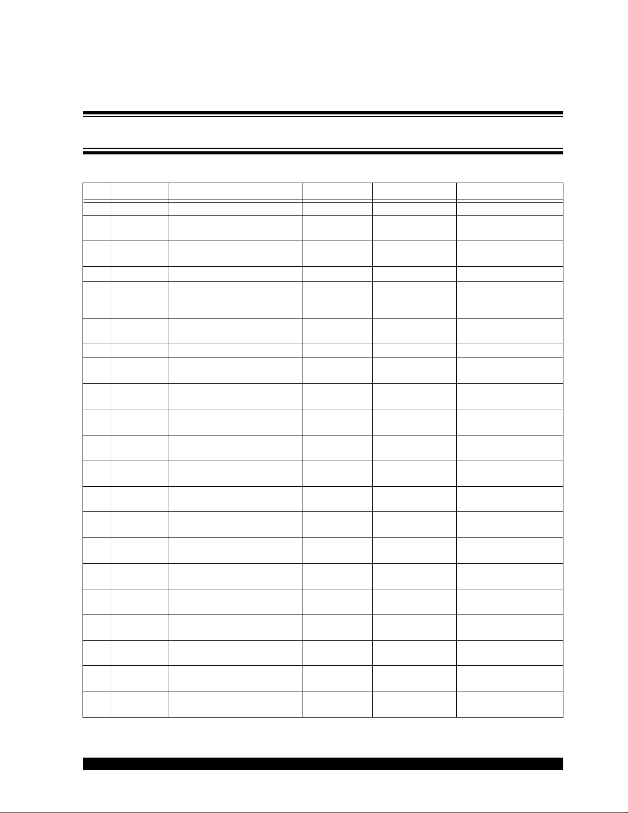
Appendix B. Bill Of Materials (BOM)
TABLE B-1: BILL OF MATERIALS
Qty Reference Description Distributor Manufacturer Part Number
3 C1, C2, C4 47 µF +80/-20%, 6.3VDC, 1210 NA muRata
2 C3, C5 Capacitor, 10 µF, 10V, Ceramic,
X7R 0603
1 C6 Capacitor, 33 mF, 16V,
Ceramic, X5R 20% 1812
2 D1, D3 Diode, Schottky, 30V, 3A, SMA Digi-Key Diodes Inc. B330A-13
3 D2, D4, D5 LED, 636NM, Super RED,
0805 SMD
2 F1, F2 Polyswitch, 2.0A, Reset Fuse,
SMD
2 L1, L2 Inductor, 3.3 µH, SMT NA Coilcraft
2 Q1, Q2 HEX/MOS, N-CH, 20V, 4.2A,
SOT-23
2 R1, R9 Resistor, 100Ω, 1/16W, 1%,
0603 SMD
4 R2, R8, R10,
R14
1 R3 Resistor, 3.09 kΩ, 1/16W, 1%,
2 R4, R13 Resistor, .10Ω, 1/10W, 5%,
2 R5,R12 Resistor, 73.2 kΩ, 1/16W, 1%,
2 R6, R15 Resistor, 1.00 kΩ, 1/16W, 1%,
1 R7 Resistor, 562Ω, 1/10W, 1%,
1 R11 Resistor, 8.87 kΩ, 1/16W, 1%,
1 R16, R17 Resistor, 221Ω, 1/10W, 1%,
10 TP1-TP10 PC Test Point, Compact, SMT Digi-Key Keystone
1 U1 Boost Controller, MCP1651 Microchip
1 U2 Boost Controller, MCP1653 Microchip
1 B1, B2, B3, B4Bumpon, Hemisphere, .44x.20,
Resistor, 49.9 kΩ, 1/16W, 1%,
0603 SMD
0603 SMD
0603
0603 SMD
0603 SMD
0805 SMD
0603 SMD
0805 SMD
Black
Digi-Key
Digi-Key TDK
Digi-Key Lumex
Digi-Key Raychem
Digi-Key International
Digi-Key Panasonic
Digi-Key Panasonic – ECG ERJ-3EKF4992V
Digi-Key Panasonic – ECG ERJ-3EKF3091V
Digi-Key Panasonic – ECG ERJ-3RSJR10V
Digi-Key Panasonic – ECG ERJ-3EKF7322V
Digi-Key Panasonic – ECG ERJ-3EKF1001V
Digi-Key Panasonic – ECG ERJ-6ENF5620V
Digi-Key Panasonic – ECG ERJ-3EKF8871V
Digi-Key Panasonic – ECG ERJ-6ENF2210V
Technology Inc.
Technology Inc.
Digi-Key 3M
®
Opto/Components
Corporation
Electronics
Microchip
Technology Inc.
Microchip
Technology Inc.
Note: SMT denotes surface-mount package
®
®
Kemet
®
®
Inc.
Rectifier
®
– ECG ERJ-3EKF1000V
®
/ESM SJ-5003 (BLACK)
GJ232CF50J476ZD01K
C0603C104K8RACTU
C4532X5R1C336M
SML-LX0805SIC-TR
®
MINISMDC200-2
®
DO1813HC
IRLML2502TR
®
5016
MCP1651R
MCP1653S
2004 Microchip Technology Inc. DS51462A-page 15
Page 20

M
W
ORLDWIDE SALES AND SERVICE
AMERICAS
Corporate Office
2355 West Chandler B lvd.
Chandler, AZ 85224-6199
Tel: 480-792-7200
Fax: 480-792-7277
Technical Support: 480-792-7627
Web Address: http://www.microchip.com
Atlanta
3780 Mansell Road, Suite 130
Alpharetta, GA 30022
Tel: 770-640-0034
Fax: 770-640-0307
Boston
2 Lan Drive, Suit e 120
Westford, MA 01886
Tel: 978-692-3848
Fax: 978-692-3821
Chicago
333 Pierce Road, S uite 180
Itasca, IL 60143
Tel: 630-285-0071
Fax: 630-285-0075
Dallas
4570 Westgrove Drive, Suite 160
Addison, TX 75001
Tel: 972-818-7423
Fax: 972-818-2924
Detroit
Tri-Atria Office Building
32255 Northwestern Highway, Suite 190
Farmington Hills, MI 48334
Tel: 248-538-2250
Fax: 248-538-2260
Kokomo
2767 S. Albright Road
Kokomo, IN 46902
Tel: 765-864-8360
Fax: 765-864-8387
Los Angeles
18201 Von Karman, Suite 10 90
Irvine, CA 92612
Tel: 949-263-1888
Fax: 949-263-1338
San Jose
1300 Terra Bella Avenue
Mountain View, CA 94043
Tel: 650-215-1444
Fax: 650-961-0286
Toro nto
6285 Northam Drive, Suite 108
Mississauga, Ontario L4V 1X5, Canada
Tel: 905-673-0699
Fax: 905-673-6509
ASIA/PACIFIC
Australia
Suite 22, 41 Rawson Street
Epping 2121, NSW
Australia
Tel: 61-2-9868-6733
Fax: 61-2-9868-6755
China - Beijing
Unit 706B
Wan Tai Bei Hai Bldg.
No. 6 Chaoyangmen Bei Str.
Beijing, 100027, China
Tel: 86-10-85282100
Fax: 86-10-85282104
China - Chengdu
Rm. 2401-2402, 24 th Floor,
Ming Xing Financial Tower
No. 88 TIDU Street
Chengdu 610016, China
Tel: 86-28-86766200
Fax: 86-28-86766599
China - Fuzhou
Unit 28F, World Trade Plaza
No. 71 Wusi Road
Fuzhou 350001, China
Tel: 86-591-7503506
Fax: 86-591-7503521
China - Hong Kong SAR
Unit 901-6, Tower 2, Metroplaza
223 Hing Fong Ro ad
Kwai Fong, N.T., Hong Kong
Tel: 852-2401-1200
Fax: 852-2401-3431
China - Shanghai
Room 701, Bldg. B
Far East International Plaza
No. 317 Xian Xia Road
Shanghai, 200051
Tel: 86-21-6275-5700
Fax: 86-21-6275-5060
China - Shenzhen
Rm. 1812, 18/F, Building A, United Plaza
No. 5022 Binhe Roa d, Futian District
Shenzhen 518033, China
Tel: 86-755-82901380
Fax: 86-755-8295-1393
China - Shunde
Room 401, Hongjian Building, No. 2
Fengxiangnan Road, Ronggui Town, Shunde
District, Foshan City, Guangdong 528303, China
Tel: 86-757-28395507 Fax: 86-757-28395571
China - Qingdao
Rm. B505A, Fullhope Plaza,
No. 12 Hong Kong Central Rd.
Qingdao 266071, China
Tel: 86-532-5027355 Fax: 86-532-5027205
India
Divyasree Chamb ers
1 Floor, Wing A (A3/A4)
No. 11, O’Shaugnessey Road
Bangalore, 560 025, India
Tel: 91-80-22290061 Fax: 91-80-22290062
Japan
Benex S-1 6F
3-18-20, Shinyokohama
Kohoku-Ku, Yokohama-shi
Kanagawa, 222-0033, Japan
Tel: 81-45-471- 6166 Fax: 81-45-471 -6122
Korea
168-1, Youngbo Bldg. 3 Floor
Samsung-Dong, Kangnam-Ku
Seoul, Korea 135-882
Tel: 82-2-554-7200 Fax: 82-2-558-5932 or
82-2-558-5934
Singapore
200 Middle Road
#07-02 Prime Cen tre
Singapore, 188980
Tel: 65-6334-8870 Fax: 65-6334-8850
Taiw an
Kaohsiung Branch
30F - 1 No. 8
Min Chuan 2nd Road
Kaohsiung 806, Taiwan
Tel: 886-7-536-4818
Fax: 886-7-53 6-4803
Taiw an
Taiwan Branch
11F-3, No. 207
Tung Hua North Road
Taipei, 105, Taiwan
Tel: 886-2-2717-7175 Fax: 886-2-25 45-0139
EUROPE
Austria
Durisolstrasse 2
A-4600 Wels
Austria
Tel: 43-7242-2244-399
Fax: 43-7242-2244-393
Denmark
Regus Business Centre
Lautrup hoj 1-3
Ballerup DK-2750 Denmark
Tel: 45-4420-9895 Fax: 45-4420-9910
France
Parc d’Activite du M oulin de Massy
43 Rue du Saule Trapu
Batiment A - ler Etage
91300 Massy, France
Tel: 33-1-69-53-63-20
Fax: 33-1-69-30-90-79
Germany
Steinheilstrasse 10
D-85737 Ismaning, Germany
Tel: 49-89-627-144-0
Fax: 49-89-627-144-44
Italy
Via Quasimodo, 12
20025 Legnano (MI)
Milan, Italy
Tel: 39-0331-742611
Fax: 39-0331-466781
Netherlands
P. A. De Biesbosch 14
NL-5152 SC Drunen, Netherlands
Tel: 31-416-690399
Fax: 31-416-690340
United Kingdom
505 Eskdale Road
Winnersh Triangle
Wokingham
Berkshire, England RG41 5TU
Tel: 44-118-921-5869
Fax: 44-118-921-5820
02/17/04
DS51462A-page 16 2004 Microchip Technology Inc.
 Loading...