

Page 1
maXTouch Curiosity Pro Users Guide
Preface
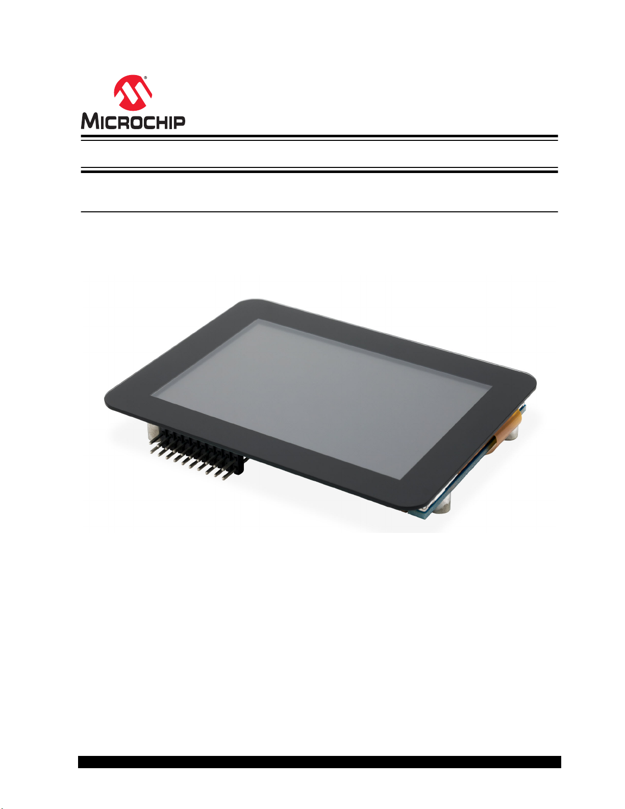
The maXTouch® Curiosity Pro (AC320007) is an extension board to the Curiosity MCU kit family line and Atmel
Xplained Pro evaluation platform, which enables users to experiment with graphical user interface (GUI) applications
with maXTouch and LCD.
The figure below illustrates the maXTouch Curiosity Pro board.
© 2020 Microchip Technology Inc.
DS70005414B-page 1
Page 2

Table of Contents
Preface........................................................................................................................................................... 1
1. Introduction............................................................................................................................................. 3
1.1. Features....................................................................................................................................... 3
1.2. Kit Overview................................................................................................................................. 3
1.3. Additional Resources................................................................................................................... 3
2. Overview................................................................................................................................................. 4
2.1. maXTouch® Capacitive Touchscreen Controller.......................................................................... 4
2.2. maXTouch® Controller Interface...................................................................................................4
3. Getting Started........................................................................................................................................ 5
3.1. Connecting maXTouch Curiosity Pro to the Curiosity Board or Xplained Pro Board ...................5
4. Curiosity and Xplained Pro Boards......................................................................................................... 6
4.1. Curiosity Board or Xplained Pro Headers and Connectors.......................................................... 6
4.2. maXTouch Parallel LCD Extension Connector.............................................................................6
4.3. Hardware Connection at J2..........................................................................................................7
4.4. FPC or FFC Connector Pinout..................................................................................................... 7
4.5. maxTouch LCD Extension Header Implementation .....................................................................8
4.6. Interface Selector (SW1).............................................................................................................. 9
4.7. Debug Header.............................................................................................................................. 9
5. Specifications........................................................................................................................................ 11
6. Schematics............................................................................................................................................13
7. Mounting............................................................................................................................................... 14
8. Document Revision History...................................................................................................................15
The Microchip Website.................................................................................................................................16
Product Change Notification Service............................................................................................................16
Customer Support........................................................................................................................................ 16
Microchip Devices Code Protection Feature................................................................................................ 16
Legal Notice................................................................................................................................................. 16
Trademarks.................................................................................................................................................. 17
Quality Management System....................................................................................................................... 17
Worldwide Sales and Service.......................................................................................................................18
© 2020 Microchip Technology Inc.
DS70005414B-page 2
Page 3

1. Introduction
This section describes Microchip maXTouch Curiosity Pro features and overview of the maXTouch Curiosity Pro kit.
1.1 Features
The following are key features of the Microchip maXTouch Curiosity Pro board:
• Display
– 3.5 inch display module
– ILI9488 LCD driver
– 320 x 480 resolution
– 30 ms maximum response time
– White back light
– Parallel interface (up to 18 bit)
– Parallel RGB interface
– 3-wire and 4-wire SPI interface
• Touch
– maXTouch capacitive touch screen controller
– Supports up to 4 touches
• Cover panel
– 1.1 mm soda-lime glass
• Xplained Pro hardware identification system
Kit contents
• One 3.5 inch display module
• One 50-way flexible flat cable (FFC)
• One 20-way ribbon cable (also known as multi-wire planar cable)
Introduction
1.2 Kit Overview
The Microchip maXTouch Curiosity Pro is an extension board for the Xplained Pro platform with a 320 x 480 RGB
LCD and a capacitive touch sensor with a maXTouch controller. The LCD can be controlled using different interfaces,
such as 3-wire and 4-wire SPI, Parallel, and RGB Parallel interface mode using the DIP switch to select the interface.
The maXTouch Curiosity Pro kit can be connected to any Curiosity boards or Xplained Pro standard extension
header, any curiosity Pro or Ultra kit, and many other Microchip MCUs using the 20-pin header, but is limited to 3-wire
and 4-wire SPI mode.
The maXTouch Curiosity Pro also features a standard LCD connector (FFC), which enables using the parallel
interfaces. Both connectors, FFC and 20-pin header, feature a SPI interface for the LCD and I2C for the maXTouch
device.
1.3 Additional Resources
For additional information, refer to these websites:
• ILI Technology Corp ILI9488 Driver IC (www.ilitek.com)
• Precision Design Associates (http://www.pdaatl.com/index.htm)
© 2020 Microchip Technology Inc.
DS70005414B-page 3
Page 4

2. Overview
2.1 maXTouch® Capacitive Touchscreen Controller
The module touch screen interface is based on the Atmel maXTouch mXT336U Touch Controller and operates on the
touch sensor at connector J4. The touch controller scans the touch sensor and signals the host with an active-low
interrupt signal (~MXT_CHG on J2 & J3) when a new touch data is available. Data communication with the
maXTouch controller is performed over the I2C interface (on J2 & J3). The I2C address of the touch controller is fixed
at 0 x 4A, and is not configurable.
Note: The maXTouch has pull-up resistors on the I2C SCL (R17) and SDA (R16) lines. A pull-up resistor for the
maXTouch ~CHG interrupt signal is located at R18 (10k).
2.2 maXTouch® Controller Interface
Details of the maXTouch communication protocol are beyond the scope of this document. This module is pre-loaded
with a configuration already optimized for the maXTouch touch sensor and panel, hence the developer will only focus
on interfacing with the device. When developing the maXTouch controller interface during evaluation and host
development, care should be taken to avoid changing the maXTouch configuration or committing changes to NV
storage on the maXTouch controller. To start with host interface development, users need to leverage the existing
code available from MPLAB® Harmony, which is available at https://www.microchip.com/mplab/mplab-harmony.
For additional information regarding the maXTouch devices, refer to http://www.microchip.com.
Overview
© 2020 Microchip Technology Inc.
DS70005414B-page 4
Page 5

3. Getting Started
This section covers getting started with Curiosity MCUs or Xplained Pro Quick Start.
Follow these steps to exploring the Microchip Curiosity Pro platform:
1. Download and launch MPLAB® X IDE.
2. Launch the plug-in manager and install MPLAB Harmony Code Configurator.
3. Connect the maXTouch Curiosity Pro to any Microchip Curiosity platform or Xplained Pro MCU board, and
connect a USB cable to the DEBUG USB port on the MCU board.
When the Curiosity MCU board or Xplained Pro MCU kit is connected to your computer for the first time, the
operating system will perform a driver software installation. The driver file supports 32-bit and 64-bit versions of
Microsoft® Windows® XP, Windows Vista®, Windows 7, Windows 8, and Windows 10.
After the Curiosity MCU board or Xplained Pro MCU board is powered, the green power LED will be lit and MPLAB X
IDE will auto detect which Curiosity MCU board or Xplained Pro MCU and extension boards are connected. MPLAB
X IDE will present relevant information, such as data sheets and kit documentation.
The target device is programmed and debugged by the on-board debugger, therefore no external programmer or
debugger tool is needed.
Getting Started
3.1 Connecting maXTouch Curiosity Pro to the Curiosity Board or Xplained Pro Board
Microchip maXTouch Curiosity Pro is designed to connect to the Curiosity board or Xplained Pro header marked
EXTx (x = 1 - 3). Refer to the pin out of the Curiosity MCU board or Xplained Pro evaluation kit to find out which
Xplained Pro EXT headers can be used. The FFC connector can be used if the parallel interface from the MCU to the
display is used on the kits featuring the graphical user interface. Any time only one cable must be connected.
© 2020 Microchip Technology Inc.
DS70005414B-page 5
Page 6

Curiosity and Xplained Pro Boards
4. Curiosity and Xplained Pro Boards
The Curiosity boards and Xplained Pro boards are evaluation platforms that provide a full Microchip microcontroller
experience to users. This platform consists of a series of microcontrollers and extension boards, which are integrated
with MPLAB X IDE, MPLAB Harmony drivers, demo code, support data streaming, and so on.
The Curiosity boards or Xplained Pro boards support a wide range of Xplained Pro extension boards, which are
connected through a set of standardized headers and connectors. Each extension board has an identification (ID)
chip to uniquely identify which boards are connected to a Curiosity board or Xplained Pro board. This information is
used to present relevant user guides, application notes, data sheets, and example code through MPLAB X IDE.
4.1 Curiosity Board or Xplained Pro Headers and Connectors
Table 4-1. Xplained Pro Standard Extension Header
Pin number Name Description
1 ID Communication line to the ID chip on an extension board
2 GND Ground
3 ADC(+) Analog-to-digital converter, alternatively positive part of differential ADC
4 ADC(-) Analog-to-digital converter, alternatively negative part of differential ADC
5 GPIO1 General purpose I/O
6 GPIO2 General purpose I/O
7 PWM(+) Pulse-width modulation, alternatively positive part of differential PWM
8 PWM(-) Pulse-width modulation, alternatively negative part of differential PWM
9 IRQ/GPIO Interrupt request line or general purpose I/O
10 SPI_SS_B/GPIO Slave select for SPI or general purpose I/O
11 I2C_SDA Data line for I2C interface. Always implemented, bus type.
12 I2C_SCL Clock line for I2C interface. Always implemented, bus type.
13 UART_RX Receiver line of target device UART
14 UART_TX Transmitter line of target device UART
15 SPI_SS_A Slave select for SPI. Should preferably be unique.
16 SPI_MOSI Master Out Slave In (MOSI) line of serial peripheral interface. Always
implemented, bus type
17 SPI_MISO Master In Slave Out (MISO) line of serial peripheral interface. Always
implemented, bus type.
18 SPI_SCK Clock for serial peripheral interface. Always implemented, bus type.
19 GND Ground
20 VCC Power for extension board
4.2 maXTouch Parallel LCD Extension Connector
The LCD connector can be connected to display extensions that have a parallel interface. The connector implements
signals for an MCU parallel bus interface and a LCD controller interface, as well as signals for a touch controller. For
connector pin-out definition, refer to maXTouch parallel LCD Connector.
© 2020 Microchip Technology Inc.
DS70005414B-page 6
Page 7

Note: Usually only one display interface is implemented, either the LCD controller or the MCU bus interface. A FPC
or FFC connector with 50 pins and 0.5 mm pitch is used for the LCD connector.
4.3 Hardware Connection at J2
The FFC must be inserted with flex contacts facing down toward the PCB.
4.4 FPC or FFC Connector Pinout
Table 4-2. maXTouch Parallel LCD Connector
Pin Number Name RGB Interface Description MCU Description
1 ID Communication line to the ID chip on an extension board
2 GND Ground
3 D0 Data Line
4 D1 Data Line
5 D2 Data Line
Curiosity and Xplained Pro Boards
6 D3 Data Line
7 GND Ground
8 D4 Data Line
9 D5 Data Line
10 D6 Data Line
11 D7 Data Line
12 GND Ground
13 D8 Data Line
14 D9 Data Line
15 D10 Data Line
16 D11 Data Line
17 GND Ground
18 D12 Data Line
19 D13 Data Line
20 D14 Data Line
21 D15 Data Line
22 GND Ground
23 D16 Data Line
24 D17 Data Line
25 D18 Data Line
26 D19 Data Line
27 GND Ground
28 D20 Data Line
© 2020 Microchip Technology Inc.
DS70005414B-page 7
Page 8
Curiosity and Xplained Pro Boards
29 D21 Data Line
30 D22 Data Line
31 D23 Data Line
32 GND Ground
33 PCLK/CMD DATASEL Pixel clock Display RAM select. One address line of the
MCU for display where it is possible to select
either register or data interface
34 VSYNC/CS Vertical Synchronization Chip select
35 HSYNC/WE Horizontal Synchronization Write-enable signal
36 DATA ENABLE/RE Data-enable signal Read-enable signal
37 SPI SCK Clock for serial peripheral interface
38 SPI MOSI Master Out Slave In (MOSI) of serial peripheral interface
39 SPI MISO Master In Slave Out (MISO) of serial peripheral interface
40 SPI SS Slave select for serial peripheral interface (SPI). Preferably a dedicated pin.
41 ENABLE Display enable
42 I2C_SDA Data line for I2C interface. Always implemented, bus type.
43 I2C_SCL Clock line for I2C interface. Always implemented, bus type.
44 IRQ1 Interrupt
45 IRQ2 Interrupt
46 PWM Back light control
47 RESET Extension reset
48 VCC 3.3V power supply for extension board
49 VCC 3.3V power supply for extension board
50 GND Ground
4.5 maxTouch LCD Extension Header Implementation
The following table provides the signals used by the maXTouch LCD.
Table 4-3. Signals Used by the maXTouch LCD
Pin number Name Description
1 ID Communication line to the ID chip on an extension board
2 GND Ground
3 NC Not connected
4 NC Not connected
5 GPIO1 General purpose I/O
6 NC Not connected
7 PWM(+) Pulse-width modulation, alternatively positive part of differential PWM
8 NC Not connected
© 2020 Microchip Technology Inc.
DS70005414B-page 8
Page 9

Curiosity and Xplained Pro Boards
...........continued
Pin number Name Description
9 IRQ/GPIO Interrupt request line or general purpose I/O
10 SPI_SS_B/GPIO Slave select for SPI or general purpose I/O
11 I2C_SDA Data line for I2C interface. Always implemented, bus type.
12 I2C_SCL Clock line for I2C interface. Always implemented, bus type.
13 NC Not connected
14 NC Not connected
15 SPI_SS_A Slave select for SPI. must preferably be unique.
16 SPI_MOSI Master Out Slave In (MOSI) line of serial peripheral interface. Always
implemented, bus type
17 SPI_MISO Master In Slave Out line (MISO) of serial peripheral interface. Always
implemented, bus type.
18 SPI_SCK Clock for serial peripheral interface. Always implemented, bus type.
19 GND Ground
20 VCC Power for extension board
4.6 Interface Selector (SW1)
The maXTouch Pro LCD has a series of selector switches to control the mode the ILI9844 controller operates in.
These switches can be found on the back of the LCD. The table below details how the switches change the mode.
and the switch settings have to match the software that is loaded on the host microcontroller.
IM2 IM1 IM0 Interface Pins in use
0 0 0 18-bit parallel bus DB[17:0], CS, D/C, WE, RE
0 0 1 9-bit parallel bus DB[8:0], CS, D/C, WE, RE
0 1 0 16-bit parallel bus DB[15:0], CS, D/C, WE, RE
0 1 1 8-bit parallel bus DB[7:0], CS, D/C, WE, RE
1 0 0 Not Supported
1 0 1 3-wire/9-bit SPI mode MOSI, MISO, SCLK, CS,
1 1 0 Not Supported
1 1 1 4-wire/8-bit SPI mode MOSI, MISO, SCLK, CS, D/C
4.7 Debug Header
Extra debug connections of the maXTouch controller is provided for easy access.
Pin Number Pin Name Pin Description
1 NC No connect
2 NC No connect
3 IRQ Interrupt (maXTouch) Active-Low
4 Reset Reset (maxTouch) Active-Low
© 2020 Microchip Technology Inc.
DS70005414B-page 9
Page 10

Curiosity and Xplained Pro Boards
...........continued
Pin Number Pin Name Pin Description
5 I2C_SDA Data line for I2C interface. Always implemented, bus type.
6 I2C_SCL Clock line for I2C interface. Always implemented, bus type.
7 VCC 3.3V power supply for extension board
8 GND Ground
9 Debug Data Debug output
10 Debug Clock Debug clock
© 2020 Microchip Technology Inc.
DS70005414B-page 10
Page 11

5. Specifications
CAUTION
Table 5-1. Module Parameters
Parameter Value
Module size 3.5 inch
Overall dimensions 69.96 mm (H) x 94.44 mm (W) x 8.7 mm (T)
Overall weight 48.8 gm
Table 5-2. Absolute Maximum Specifications
Parameter Value
Operating temp 0ºC to +70ºC
Storage temp -30ºC to +80ºC
VDD -0.5 to +6V
VDDIO -0.5 to +3.6V
Maximum continuous pin current, any control or drive pin ±40 mA
Specifications
Voltage forced onto any pin -0.5V to (VDD + 0.5) Volts
Stresses beyond those listed in the above table may cause permanent damage to the device. This is a
stress rating only and the functional operation of the device at these or other conditions beyond those
indicated in the operational sections of this specification are not implied. Exposure to absolute maximum
specification conditions for extended periods may affect device reliability.
Table 5-3. Recommended Operating Conditions
Parameter Value
VIN 3.3V
Supply ripple + noise ±20 mV
Table 5-4. DC Specifications
Parameter Description Min. Typ Max. Units Notes
VIL Low-input logic level -0.5 - 0.3 VDD V 1.8V <VDD <3.3V
VHL High- input logic level 0.7 VDD - V 1.8V <VDD <3.3V
VOL Low- output voltage - 0.2 VDD V
VOH High- output voltage 0.8 VDD - - V
IIL Input leakage current - 1 μA
VIN = 3.3V, VDD = 2.8 VDC, TA = recommended range, unless otherwise noted.
Table 5-5. I2C Compatible Bus Specifications
Parameter Operation
Touchscreen controller address 0x4A
© 2020 Microchip Technology Inc.
DS70005414B-page 11
Page 12

Specifications
...........continued
Parameter Operation
Maximum bus speed (SCL) 1 MHz
I2C specification Version 2.1
Bus voltage 3.3V
Table 5-6. LCD Module Specifications
Parameter Value
Display size 3.5 inch
LCD type -Si TFT
Display mode TN/Transmissive
Resolution 320 x RGB x 480
View direction (Best Image) 6 O’clock (Portrait, LCD flex end at bottom)
Dimensions 54.16 mm (H) x 84.21 mm (W) x 2.15 mm (T)
Active area 48.96 mm x 73.44 mm
Pixel size 0.153 mm x 0.153 mm
Pixel arrangement Stripe
Display colors 262K
Table 5-7. Backlight Specifications
Parameter Description Min. Typ. Max. Units
VF Forward Voltage (TA = 25 ºC, IF = 15 mA) - 3.2 3.5 V
IF Forward Current (TA = 25ºC, VF = 3.2A), per LED - 20 - mA
LED Configuration 6x White LED in parallel
LV Luminance 280 300 - Cd/m2
Avg Uniformity 80 85 - %
Pd Power Dissipation - 384 - mW
Vak Backlight Driving Voltage - 3.3 3.5 V
© 2020 Microchip Technology Inc.
DS70005414B-page 12
Page 13
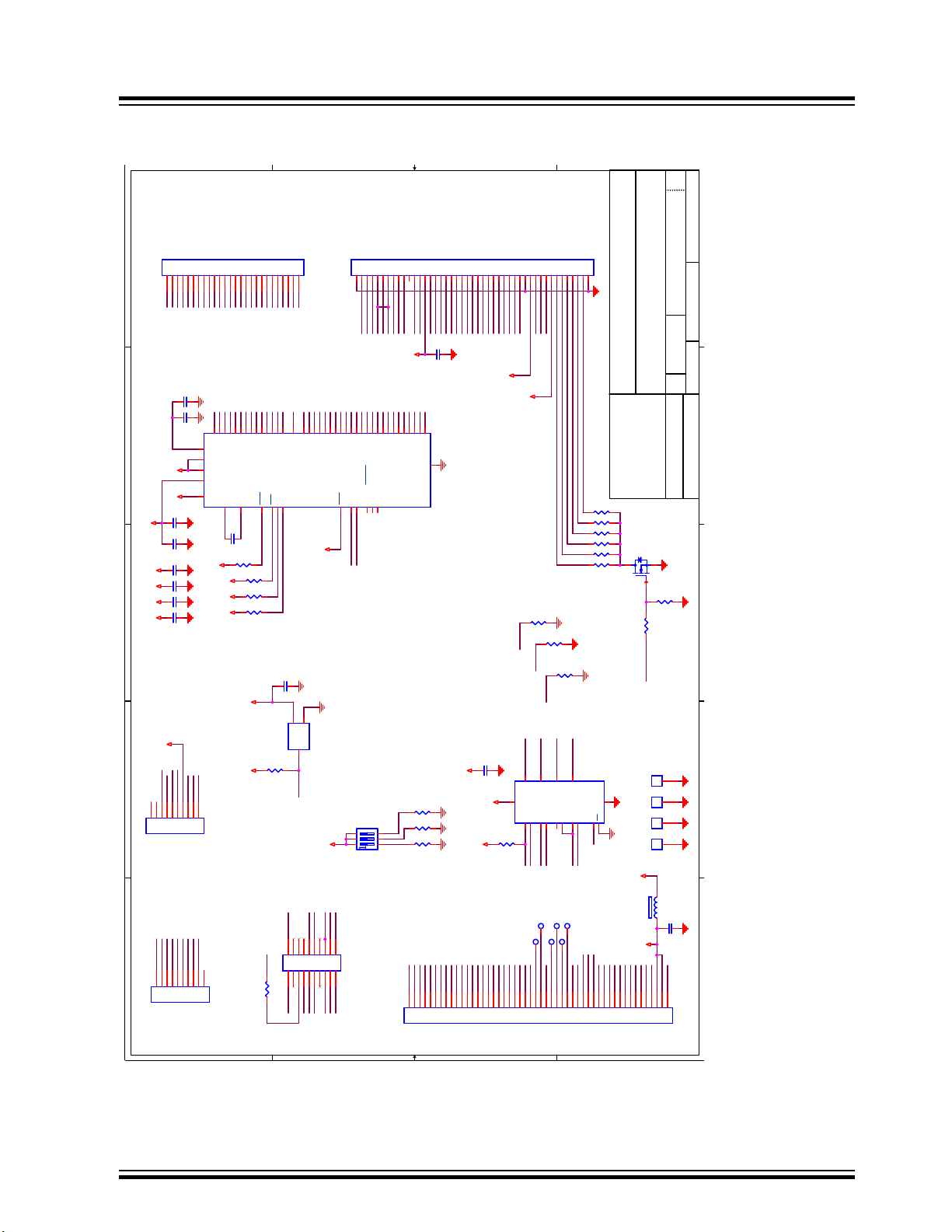
6. Schematics
5
5
4
4
3
3
2
2
1
1
D
D
C C
B
B
A
A
Touchscreen
LCD
IM2 IM1 IM0 Interface
0 0 0 MIPI-DBI Type B 24-bit bus (DB_EN = 1) NOT SUPPORTED
0 0 0 MIPI-DBI Type B 18-bit bus (DB_EN = 0)
0 0 1 MIPI-DBI Type B 9-bit bus
0 1 0 MIPI-DBI Type B 16-bit bus
0 1 1 MIPI-DBI Type B 8-bit bus
1 0 1 MIPI-DBI Type C Option 1 (3-line SPI) RGB
1 1 0 MIPI DSI NOT Supported
1 1 1 MIPI-DBI Type C Option 3 (4-line SPI)
Host Interface
Debug Header
XPRO Legacy Header
0
1
PDA Standard 10 Pos FFC
~Reset
X0X1X2
X3X4X5X6X7X8X9
X10
X11
X12
X13
Y7Y6Y5Y4Y3Y2Y1
Y0
SCL
SDA
~CHG_mxt
Debug_Data
Debug_CK
Y7Y6Y5Y4Y3
Y2Y1Y0
GND
GND
GND
GND
D16
D17
~SS
MISO
MOSID8SCK/WR
D9
D10
D11
D12
D13
D14
D15
D0
D1
D2D3D4
D5
D6
D7
HSYNC
VSYNC
DE
~Reset
RD
IM0
IM1
IM2
LEDK1
LEDK2
LEDK3
LEDK4
LEDK5
LEDK6
Vin
Vin
ONE_WIRE
GND
D0
D1D2D3
GND
D4
D5
D6
D7
GND
D8D9D10
D11
GND
D12
D13
D14
D15
GND
D16
D17
GND
GND
PCLK
VSYNC/CS
HSYNC/WR
DE/RD
SCK
MOSI
MISO
~SS
DISP
SDA
SCL
~CHG_mxt
~CHG_QT
LCD_PWM
~Reset
GND
LCD_PWM
LEDA
D18
D19
D20
D21
D22
D23
HSYNC
DE
VSYNC
X0X1X2
X3X4X5
X6X7X8
X9
X10
X11
X12
X13
PCLK
D/CX
ONE_WIRE
GND
GND
~Reset
SDA SCL
~CHG_mxt
LCD_PWM
D/CX
~SS
MISO
MOSI
SCK
Vin
SCL
SDA
~CHG_mxt
GND
Debug_Data
Debug_CK
Vin
IM0
IM1
IM2
IM2
VSYNC/CS~SS
VSYNC
DE
RD DE/RD
HSYNC
SCK/WR
SCK
HSYNC/WR
Y8Y9Y10
Y11
Y12
Y13
Y14
Y15
Y16
Y17
Y18
Y19
Y20
Y21
Y22
Y23
DS0
ONE_WIRE
~Reset
~CHG_QT
GND
~Reset
~CHG_mxt
SDA
SCL
Debug_CK
Debug_Data
Vin
Vdd Vdd Vdd
Vdd
Vdd
Vdd
3V3
3V3
3V3
3V3
3V3
3V3
3V3
3V3
3V3
3V3
Vdd
XVdd
Vdd
Vdd VddVdd
3V3
Vdd
Size
Scale
CAGE Code
DWG NO
Rev
Sheet
of
This document contains confidential and
proprietary information. DO NOT disclose
any information contained within this
document without the writen permission of
the Precison Design Associates, Inc.
support@pdaatl.com
A0-R1
Precision Design Associates, Inc
10-01130
Sunday, June 02, 2019
1 1
Custom
645 Hembree Parkway, Suite G
Roswell, GA 30076
770-664-0448
Mxt336U For 3.5" Touchscreen Module
<Cage Code>
TP2
R7 7.5
R15
10k
C11
2.2uF
C10
0.1uF
R6 7.5
C9
2.2nF
R18
10k
R11
DNP
R17
4.7k
PEM3
CON1
1
TP5
C3
0.1uF
R16
4.7k
R19
47k
Q1
2N7002/SOT
312
C4
0.1uF
J2
5-1734592-0
1
2
3
45678910
111213
14
151617
18192021222324
25
26
27
28
29303132333435
363738
39
404142
43
444546
47
48
49
50
PEM4
CON1
1
C6
2.2uF
R21
10k
TP6
PEM2
CON1
1
R5 3.3k
U3
mxt336U_QFN
Y13
18
AVdd
56
X8
9
X9
10
X10
11
X11
12
X12
13
X13
14
Y1419Y15
20
TEST/DGG2_CLK
33
Vdd
30
Reset
36
SDA34SCL
35
GKEYY0/DBG_SS
41
SCAN_OUT/DBG_CLK
39
Vdd_Core
31
DS0
40
SYNC/DBG_Data
38
Vdd_IO
32
CHG
37
X0
1
X1
2
X2
3
X3
4
X4
5
X5
6
X67X7
8
GKEYY2/DBG2_Data5
43
Y0
55
Y1
54
Y2
53
Y3
52
Y4
51
Y550Y6
49
Y7
48
Y847Y9
46
Y10
45
Y1144Y1217Y1621Y17
22
Y18
23
Y19
24
Y20
25
Y21
26
Y22
27
XVdd
15
Y23
28
ExtCap1
16
GKEYY1/DBG2_Data4
42
PAD_GND
57
ExtCap0
29
U1
ATSHA204
IO
1
Vdd
2
GND
3
TP1
C12
2.2uF
J5
TE 1-1734592-0
1234567
8
9
10
PEM1
CON1
1
R4 7.5
C1
10uF
R3 7.5
C5
0.1uF
R12
10k
R10
DNP
J4
CON26
1
2
345
6
7
8
9
10
11
121314
15
16
17
181920
21
22
23
242526
R2 7.5
TP3
J1
CON45
123
456
789
10
11
121314
15
16
17
181920
21
22
23
2425262728
293031
323334
3536373839
40
41
424344
45
SW1
219-3LPSTR
R9
0
TP4
R14
10k
C2
10uF
C13
0.1uF
R20
4.7k
U2
TS3A5018
IN
1
NC12NO1
3
COM1
4
NC2
5
NO2
6
COM2
7
GND
8
COM3
9
NO310NC3
11
COM4
12
NO4
13
NC4
14
EN
15
Vdd
16
R13
10k
L1
MMZ1608R601A
C8
2.2uF
R1 1k
J6
CON10
1234567
8910
R8 7.5
C7
0.1uF
J3
1 2
3 4
5 6
7 8
9
10
11 12
13 14
15 16
17 18
19 20
Schematics
© 2020 Microchip Technology Inc.
DS70005414B-page 13
Page 14
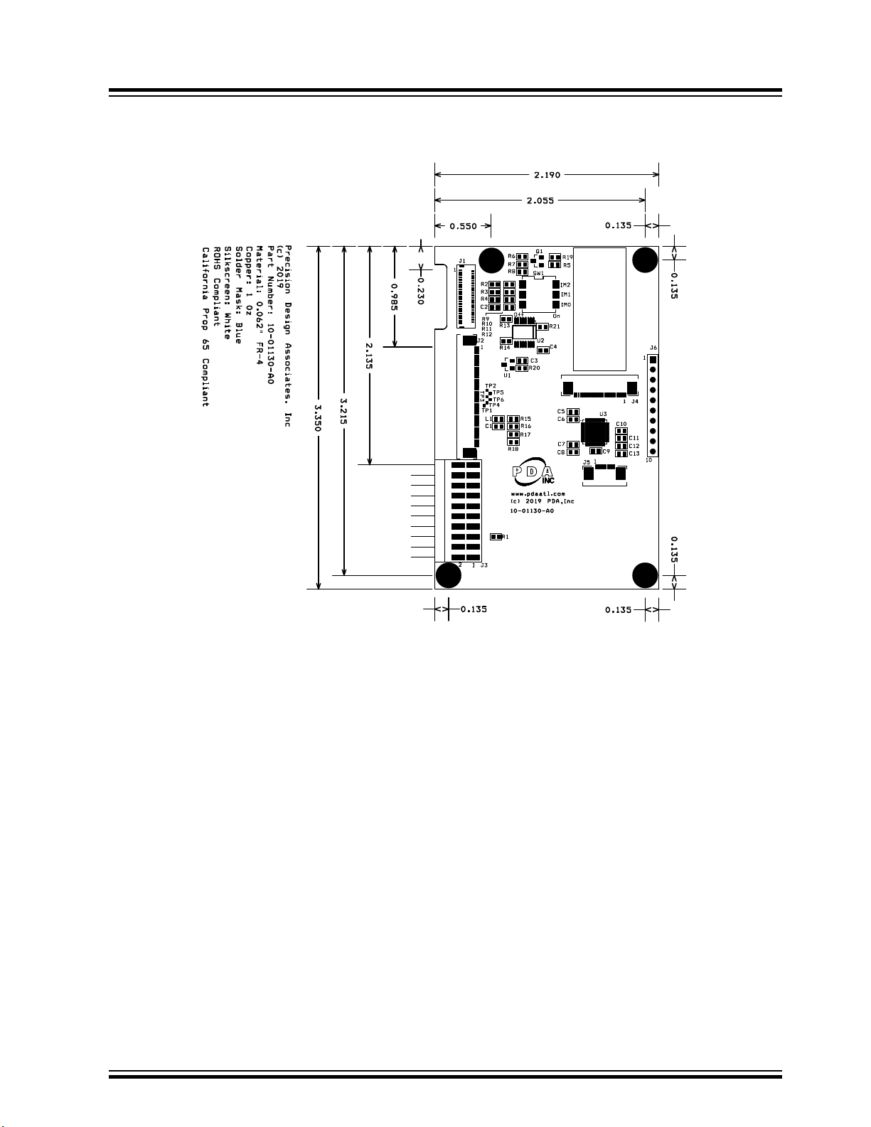
7. Mounting
Mounting
© 2020 Microchip Technology Inc.
DS70005414B-page 14
Page 15

8. Document Revision History
Revision B - 03/2020
Updated the Features section with the following information:
• Removed erroneous information regarding a projected capacitive multi-touch controller
• Updated the size of the display module in Kit Contents to 3.5 inches
Revision A - 01/2020
This is the initial released version of this document.
Document Revision History
© 2020 Microchip Technology Inc.
DS70005414B-page 15
Page 16

The Microchip Website
Microchip provides online support via our website at http://www.microchip.com/. This website is used to make files
and information easily available to customers. Some of the content available includes:
• Product Support – Data sheets and errata, application notes and sample programs, design resources, user’s
guides and hardware support documents, latest software releases and archived software
• General Technical Support – Frequently Asked Questions (FAQs), technical support requests, online
discussion groups, Microchip design partner program member listing
• Business of Microchip – Product selector and ordering guides, latest Microchip press releases, listing of
seminars and events, listings of Microchip sales offices, distributors and factory representatives
Product Change Notification Service
Microchip’s product change notification service helps keep customers current on Microchip products. Subscribers will
receive email notification whenever there are changes, updates, revisions or errata related to a specified product
family or development tool of interest.
To register, go to http://www.microchip.com/pcn and follow the registration instructions.
Customer Support
Users of Microchip products can receive assistance through several channels:
• Distributor or Representative
• Local Sales Office
• Embedded Solutions Engineer (ESE)
• Technical Support
Customers should contact their distributor, representative or ESE for support. Local sales offices are also available to
help customers. A listing of sales offices and locations is included in this document.
Technical support is available through the website at: http://www.microchip.com/support
Microchip Devices Code Protection Feature
Note the following details of the code protection feature on Microchip devices:
• Microchip products meet the specification contained in their particular Microchip Data Sheet.
• Microchip believes that its family of products is one of the most secure families of its kind on the market today,
when used in the intended manner and under normal conditions.
• There are dishonest and possibly illegal methods used to breach the code protection feature. All of these
methods, to our knowledge, require using the Microchip products in a manner outside the operating
specifications contained in Microchip’s Data Sheets. Most likely, the person doing so is engaged in theft of
intellectual property.
• Microchip is willing to work with the customer who is concerned about the integrity of their code.
• Neither Microchip nor any other semiconductor manufacturer can guarantee the security of their code. Code
protection does not mean that we are guaranteeing the product as “unbreakable.”
Code protection is constantly evolving. We at Microchip are committed to continuously improving the code protection
features of our products. Attempts to break Microchip’s code protection feature may be a violation of the Digital
Millennium Copyright Act. If such acts allow unauthorized access to your software or other copyrighted work, you
may have a right to sue for relief under that Act.
Legal Notice
Information contained in this publication regarding device applications and the like is provided only for your
convenience and may be superseded by updates. It is your responsibility to ensure that your application meets with
© 2020 Microchip Technology Inc.
DS70005414B-page 16
Page 17

your specifications. MICROCHIP MAKES NO REPRESENTATIONS OR WARRANTIES OF ANY KIND WHETHER
EXPRESS OR IMPLIED, WRITTEN OR ORAL, STATUTORY OR OTHERWISE, RELATED TO THE INFORMATION,
INCLUDING BUT NOT LIMITED TO ITS CONDITION, QUALITY, PERFORMANCE, MERCHANTABILITY OR
FITNESS FOR PURPOSE. Microchip disclaims all liability arising from this information and its use. Use of Microchip
devices in life support and/or safety applications is entirely at the buyer’s risk, and the buyer agrees to defend,
indemnify and hold harmless Microchip from any and all damages, claims, suits, or expenses resulting from such
use. No licenses are conveyed, implicitly or otherwise, under any Microchip intellectual property rights unless
otherwise stated.
Trademarks
The Microchip name and logo, the Microchip logo, Adaptec, AnyRate, AVR, AVR logo, AVR Freaks, BesTime,
BitCloud, chipKIT, chipKIT logo, CryptoMemory, CryptoRF, dsPIC, FlashFlex, flexPWR, HELDO, IGLOO, JukeBlox,
KeeLoq, Kleer, LANCheck, LinkMD, maXStylus, maXTouch, MediaLB, megaAVR, Microsemi, Microsemi logo, MOST,
MOST logo, MPLAB, OptoLyzer, PackeTime, PIC, picoPower, PICSTART, PIC32 logo, PolarFire, Prochip Designer,
QTouch, SAM-BA, SenGenuity, SpyNIC, SST, SST Logo, SuperFlash, Symmetricom, SyncServer, Tachyon,
TempTrackr, TimeSource, tinyAVR, UNI/O, Vectron, and XMEGA are registered trademarks of Microchip Technology
Incorporated in the U.S.A. and other countries.
APT, ClockWorks, The Embedded Control Solutions Company, EtherSynch, FlashTec, Hyper Speed Control,
HyperLight Load, IntelliMOS, Libero, motorBench, mTouch, Powermite 3, Precision Edge, ProASIC, ProASIC Plus,
ProASIC Plus logo, Quiet-Wire, SmartFusion, SyncWorld, Temux, TimeCesium, TimeHub, TimePictra, TimeProvider,
Vite, WinPath, and ZL are registered trademarks of Microchip Technology Incorporated in the U.S.A.
Adjacent Key Suppression, AKS, Analog-for-the-Digital Age, Any Capacitor, AnyIn, AnyOut, BlueSky, BodyCom,
CodeGuard, CryptoAuthentication, CryptoAutomotive, CryptoCompanion, CryptoController, dsPICDEM,
dsPICDEM.net, Dynamic Average Matching, DAM, ECAN, EtherGREEN, In-Circuit Serial Programming, ICSP,
INICnet, Inter-Chip Connectivity, JitterBlocker, KleerNet, KleerNet logo, memBrain, Mindi, MiWi, MPASM, MPF,
MPLAB Certified logo, MPLIB, MPLINK, MultiTRAK, NetDetach, Omniscient Code Generation, PICDEM,
PICDEM.net, PICkit, PICtail, PowerSmart, PureSilicon, QMatrix, REAL ICE, Ripple Blocker, SAM-ICE, Serial Quad
I/O, SMART-I.S., SQI, SuperSwitcher, SuperSwitcher II, Total Endurance, TSHARC, USBCheck, VariSense,
ViewSpan, WiperLock, Wireless DNA, and ZENA are trademarks of Microchip Technology Incorporated in the U.S.A.
and other countries.
SQTP is a service mark of Microchip Technology Incorporated in the U.S.A.
The Adaptec logo, Frequency on Demand, Silicon Storage Technology, and Symmcom are registered trademarks of
Microchip Technology Inc. in other countries.
GestIC is a registered trademark of Microchip Technology Germany II GmbH & Co. KG, a subsidiary of Microchip
Technology Inc., in other countries.
All other trademarks mentioned herein are property of their respective companies.
©
2019, Microchip Technology Incorporated, Printed in the U.S.A., All Rights Reserved.
ISBN: 978-1-5224-5730-5
Quality Management System
For information regarding Microchip’s Quality Management Systems, please visit http://www.microchip.com/quality.
© 2020 Microchip Technology Inc.
DS70005414B-page 17
Page 18

Worldwide Sales and Service
AMERICAS ASIA/PACIFIC ASIA/PACIFIC EUROPE
Corporate Office
2355 West Chandler Blvd.
Chandler, AZ 85224-6199
Tel: 480-792-7200
Fax: 480-792-7277
Technical Support:
http://www.microchip.com/support
Web Address:
http://www.microchip.com
Atlanta
Duluth, GA
Tel: 678-957-9614
Fax: 678-957-1455
Austin, TX
Tel: 512-257-3370
Boston
Westborough, MA
Tel: 774-760-0087
Fax: 774-760-0088
Chicago
Itasca, IL
Tel: 630-285-0071
Fax: 630-285-0075
Dallas
Addison, TX
Tel: 972-818-7423
Fax: 972-818-2924
Detroit
Novi, MI
Tel: 248-848-4000
Houston, TX
Tel: 281-894-5983
Indianapolis
Noblesville, IN
Tel: 317-773-8323
Fax: 317-773-5453
Tel: 317-536-2380
Los Angeles
Mission Viejo, CA
Tel: 949-462-9523
Fax: 949-462-9608
Tel: 951-273-7800
Raleigh, NC
Tel: 919-844-7510
New York, NY
Tel: 631-435-6000
San Jose, CA
Tel: 408-735-9110
Tel: 408-436-4270
Canada - Toronto
Tel: 905-695-1980
Fax: 905-695-2078
Australia - Sydney
Tel: 61-2-9868-6733
China - Beijing
Tel: 86-10-8569-7000
China - Chengdu
Tel: 86-28-8665-5511
China - Chongqing
Tel: 86-23-8980-9588
China - Dongguan
Tel: 86-769-8702-9880
China - Guangzhou
Tel: 86-20-8755-8029
China - Hangzhou
Tel: 86-571-8792-8115
China - Hong Kong SAR
Tel: 852-2943-5100
China - Nanjing
Tel: 86-25-8473-2460
China - Qingdao
Tel: 86-532-8502-7355
China - Shanghai
Tel: 86-21-3326-8000
China - Shenyang
Tel: 86-24-2334-2829
China - Shenzhen
Tel: 86-755-8864-2200
China - Suzhou
Tel: 86-186-6233-1526
China - Wuhan
Tel: 86-27-5980-5300
China - Xian
Tel: 86-29-8833-7252
China - Xiamen
Tel: 86-592-2388138
China - Zhuhai
Tel: 86-756-3210040
India - Bangalore
Tel: 91-80-3090-4444
India - New Delhi
Tel: 91-11-4160-8631
India - Pune
Tel: 91-20-4121-0141
Japan - Osaka
Tel: 81-6-6152-7160
Japan - Tokyo
Tel: 81-3-6880- 3770
Korea - Daegu
Tel: 82-53-744-4301
Korea - Seoul
Tel: 82-2-554-7200
Malaysia - Kuala Lumpur
Tel: 60-3-7651-7906
Malaysia - Penang
Tel: 60-4-227-8870
Philippines - Manila
Tel: 63-2-634-9065
Singapore
Tel: 65-6334-8870
Taiwan - Hsin Chu
Tel: 886-3-577-8366
Taiwan - Kaohsiung
Tel: 886-7-213-7830
Taiwan - Taipei
Tel: 886-2-2508-8600
Thailand - Bangkok
Tel: 66-2-694-1351
Vietnam - Ho Chi Minh
Tel: 84-28-5448-2100
Austria - Wels
Tel: 43-7242-2244-39
Fax: 43-7242-2244-393
Denmark - Copenhagen
Tel: 45-4450-2828
Fax: 45-4485-2829
Finland - Espoo
Tel: 358-9-4520-820
France - Paris
Tel: 33-1-69-53-63-20
Fax: 33-1-69-30-90-79
Germany - Garching
Tel: 49-8931-9700
Germany - Haan
Tel: 49-2129-3766400
Germany - Heilbronn
Tel: 49-7131-72400
Germany - Karlsruhe
Tel: 49-721-625370
Germany - Munich
Tel: 49-89-627-144-0
Fax: 49-89-627-144-44
Germany - Rosenheim
Tel: 49-8031-354-560
Israel - Ra’anana
Tel: 972-9-744-7705
Italy - Milan
Tel: 39-0331-742611
Fax: 39-0331-466781
Italy - Padova
Tel: 39-049-7625286
Netherlands - Drunen
Tel: 31-416-690399
Fax: 31-416-690340
Norway - Trondheim
Tel: 47-72884388
Poland - Warsaw
Tel: 48-22-3325737
Romania - Bucharest
Tel: 40-21-407-87-50
Spain - Madrid
Tel: 34-91-708-08-90
Fax: 34-91-708-08-91
Sweden - Gothenberg
Tel: 46-31-704-60-40
Sweden - Stockholm
Tel: 46-8-5090-4654
UK - Wokingham
Tel: 44-118-921-5800
Fax: 44-118-921-5820
© 2020 Microchip Technology Inc.
DS70005414B-page 18
 Loading...