

Page 1

EVB-USB7216
Evaluation Kit
User’s Guide
2020 Microchip Technology Inc. DS50002970A
Page 2

Note the following details of the code protection feature on Microchip devices:
• Microchip products meet the specification contained in their particular Microchip Data Sheet.
• Microchip believes that its family of products is one of the most secure families of its kind on the market today, when used in the
intended manner and under normal conditions.
• There are dishonest and possibly illegal methods used to breach the code protection feature. All of these methods, to our
knowledge, require using the Microchip products in a manner outside the operating specifications contained in Microchip’s Data
Sheets. Most likely, the person doing so is engaged in theft of intellectual property.
• Microchip is willing to work with the customer who is concerned about the integrity of their code.
• Neither Microchip nor any other semiconductor manufacturer can guarantee the security of their code. Code protection does not
mean that we are guaranteeing the product as “unbreakable.”
Code protection is constantly evolving. We at Microchip are committed to continuously improving the code protection features of our
products. Attempts to break Microchip’s code protection feature may be a violation of the Digital Millennium Copyright Act. If such acts
allow unauthorized access to your software or other copyrighted work, you may have a right to sue for relief under that Act.
Information contained in this publication regarding device applications and the like is provided only for your convenience and may be
superseded by updates. It is your responsibility to ensure that your application meets with your specifications. MICROCHIP MAKES NO
REPRESENTATIONS OR WARRANTIES OF ANY KIND WHETHER EXPRESS OR IMPLIED, WRITTEN OR ORAL, STATUTORY OR
OTHERWISE, RELATED TO THE INFORMATION, INCLUDING BUT NOT LIMITED TO ITS CONDITION, QUALITY, PERFORMANCE,
MERCHANTABILITY OR FITNESS FOR PURPOSE. Microchip disclaims all liability arising from this information and its use. Use of Micro-
chip devices in life support and/or safety applications is entirely at the buyer’s risk, and the buyer agrees to defend, indemnify and hold
harmless Microchip from any and all damages, claims, suits, or expenses resulting from such use. No licenses are conveyed, implicitly or
otherwise, under any Microchip intellectual property rights unless otherwise stated.
Trademarks
The Microchip name and logo, the Microchip logo, Adaptec, AnyRate, AVR, AVR logo, AVR Freaks, BesTime, BitCloud, chipKIT, chipKIT logo,
CryptoMemory, CryptoRF, dsPIC, FlashFlex, flexPWR, HELDO, IGLOO, JukeBlox, KeeLoq, Kleer, LANCheck, LinkMD, maXStylus, maXTouch,
MediaLB, megaAVR, Microsemi, Microsemi logo, MOST, MOST logo, MPLAB, OptoLyzer, PackeTime, PIC, picoPower, PICSTART, PIC32 logo,
PolarFire, Prochip Designer, QTouch, SAM-BA, SenGenuity, SpyNIC, SST, SST Logo, SuperFlash, Symmetricom, SyncServer, Tachyon,
TempTrackr, TimeSource, tinyAVR, UNI/O, Vectron, and XMEGA are registered trademarks of Microchip Technology Incorporated in the U.S.A. and
other countries.
APT, ClockWorks, The Embedded Control Solutions Company, EtherSynch, FlashTec, Hyper Speed Control, HyperLight Load, IntelliMOS, Libero,
motorBench, mTouch, Powermite 3, Precision Edge, ProASIC, ProASIC Plus, ProASIC Plus logo, Quiet-Wire, SmartFusion, SyncWorld, Temux,
TimeCesium, TimeHub, TimePictra, TimeProvider, Vite, WinPath, and ZL are registered trademarks of Microchip Technology Incorporated in the
U.S.A.
Adjacent Key Suppression, AKS, Analog-for-the-Digital Age, Any Capacitor, AnyIn, AnyOut, BlueSky, BodyCom, CodeGuard,
CryptoAuthentication, CryptoAutomotive, CryptoCompanion, CryptoController, dsPICDEM, dsPICDEM.net, Dynamic Average Matching, DAM,
ECAN, EtherGREEN, In-Circuit Serial Programming, ICSP, INICnet, Inter-Chip Connectivity, JitterBlocker, KleerNet, KleerNet logo, memBrain,
Mindi, MiWi, MPASM, MPF, MPLAB Certified logo, MPLIB, MPLINK, MultiTRAK, NetDetach, Omniscient Code Generation, PICDEM, PICDEM.net,
PICkit, PICtail, PowerSmart, PureSilicon, QMatrix, REAL ICE, Ripple Blocker, SAM-ICE, Serial Quad I/O, SMART-I.S., SQI, SuperSwitcher,
SuperSwitcher II, Total Endurance, TSHARC, USBCheck, VariSense, ViewSpan, WiperLock, Wireless DNA, and ZENA are trademarks of
Microchip Technology Incorporated in the U.S.A. and other countries.
SQTP is a service mark of Microchip Technology Incorporated in the U.S.A.
The Adaptec logo, Frequency on Demand, Silicon Storage Technology, and Symmcom are registered trademarks of Microchip Technology Inc. in
other countries.
GestIC is a registered trademark of Microchip Technology Germany II GmbH & Co. KG, a subsidiary of Microchip Technology Inc., in other
countries.
All other trademarks mentioned herein are property of their respective companies.
© 2020, Microchip Technology Incorporated, All Rights Reserved.
ISBN: 978-1-5224-5820-3
For information regarding Microchip’s Quality Management Systems, please visit www.microchip.com/quality.
DS50002970A-page 2 2020 Microchip Technology Inc.
Page 3

EVB-USB7216
EVALUATION KIT
USER’S GUIDE
Table of Contents
Preface ........................................................................................................................... 5
Introduction............................................................................................................ 5
Document Layout .................................................................................................. 5
Conventions Used in this Guide ............................................................................ 6
Warranty Registration............................................................................................ 7
The Microchip Website.......................................................................................... 7
Development Systems Customer Change Notification Service ............................ 7
Customer Support ................................................................................................. 8
Document Revision History ................................................................................... 8
Chapter 1. Overview
1.1 Introduction ..................................................................................................... 9
1.2 Features ......................................................................................................... 9
1.3 Block Diagram .............................................................................................. 10
1.4 References ................................................................................................... 12
1.5 Acronyms and Definitions ............................................................................. 12
Chapter 2. Getting Started
2.1 Introduction ................................................................................................... 13
2.2 Kit Contents .................................................................................................. 13
2.3 Quick Start .................................................................................................... 13
Chapter 3. Hardware Configuration
3.1 Hardware Configuration Options .................................................................. 15
3.1.1 Configuration .............................................................................................15
3.1.2 Power Source – Self Powered .................................................................. 16
3.1.3 Downstream Port Power Control ............................................................... 16
3.1.4 USB Type-C
3.1.5 LED Indicators ........................................................................................... 17
3.1.6 Switches ....................................................................................................18
3.1.7 Connector Descriptions ............................................................................. 18
3.1.8 Test Points ................................................................................................ 19
®
Appendix A. USB7216 Schematics
A.1 Introduction .................................................................................................. 21
Appendix B. Bill of Materials
B.1 Introduction .................................................................................................. 31
Appendix C. PCB Silk Screens
C.1 Introduction .................................................................................................. 37
Ports ................................................................................... 17
Worldwide Sales and Service .................................................................................... 40
2020 Microchip Technology Inc. DS50002970A-page 3
Page 4

EVB-USB7216 Evaluation Kit User’s Guide
NOTES:
DS50002970A-page 4 2020 Microchip Technology Inc.
Page 5
EVB-USB7216
EVALUATION KIT
USER’S GUIDE
Preface
NOTICE TO CUSTOMERS
All documentation becomes dated, and this manual is no exception. Microchip tools and
documentation are constantly evolving to meet customer needs, so some actual dialogs
and/or tool descriptions may differ from those in this document. Please refer to our website
(www.microchip.com) to obtain the latest documentation available.
Documents are identified with a “DS” number. This number is located on the bottom of each
page, in front of the page number. The numbering convention for the DS number is
“DSXXXXXA”, where “XXXXX” is the document number and “A” is the revision level of the
document.
®
For the most up-to-date information on development tools, see the MPLAB
Select the Help menu, and then Topics to open a list of available online help files.
IDE online help.
INTRODUCTION
This chapter contains general information that will be useful to know before using the
EVB-USB7216 Evaluation Kit. Items discussed in this chapter include:
• Document Layout
• Conventions Used in this Guide
• Warranty Registration
• The Microchip Website
• Development Systems Customer Change Notification Service
• Customer Support
• Document Revision History
DOCUMENT LAYOUT
This document describes how to use the EVB-USB7216 Evaluation Kit as a
demonstration platform optimized for portable applications. The manual layout is as
follows:
• Chapter 1. “Overview” – This chapter shows a brief description of the
EVB-USB7216 Evaluation Kit.
• Chapter 2. “Getting Started” – This chapter provides information about the
setup and operation of the EVB-USB7216 Evaluation Kit.
• Chapter 3. “Hardware Configuration” – This chapter includes information about
the hardware configuration of the EVB-USB7216 Evaluation Kit.
• Appendix A. “USB7216 Schematics” – This appendix shows the
EVB-USB7216 Evaluation Kit schematics.
• Appendix B. “Bill of Materials” – This appendix includes the EVB-USB7216
Evaluation Kit Bill of Materials (BOM).
• Appendix C. “PCB Silk Screens” – This appendix includes the EVB-USB7216
Evaluation Kit silk screens.
2020 Microchip Technology Inc. DS50002970A-page 5
Page 6

EVB-USB7216 Evaluation Kit User’s Guide
CONVENTIONS USED IN THIS GUIDE
This manual uses the following documentation conventions:
DOCUMENTATION CONVENTIONS
Description Represents Examples
Arial font:
Italic characters Referenced books MPLAB
Emphasized text ...is the only compiler...
Initial caps A window the Output window
A dialog the Settings dialog
A menu selection select Enable Programmer
Quotes A field name in a window or
dialog
Underlined, italic text with
right angle bracket
Bold characters A dialog button Click OK
N‘Rnnnn A number in verilog format,
Text in angle brackets < > A key on the keyboard Press <Enter>, <F1>
Courier New font:
Plain Courier New Sample source code #define START
Italic Courier New A variable argument
Square brackets [ ] Optional arguments mcc18 [options]
Curly brackets and pipe
character: { | }
Ellipses... Replaces repeated text var_name [,
A menu path File>Save
A tab Click the Power tab
where N is the total number of
digits, R is the radix and n is a
digit.
Filenames autoexec.bat
File paths c:\mcc18\h
Keywords _asm, _endasm, static
Command-line options -Opa+, -Opa-
Bit values 0, 1
Constants 0xFF, ‘A’
Choice of mutually exclusive
arguments; an OR selection
Represents code supplied by
user
®
IDE User’s Guide
“Save project before build”
4‘b0010, 2‘hF1
file
.o, where
any valid filename
file
can be
file
[options]
errorlevel {0|1}
var_name...]
void main (void)
{ ...
}
DS50002970A-page 6 2020 Microchip Technology Inc.
Page 7

WARRANTY REGISTRATION
Please complete the enclosed Warranty Registration Card and mail it promptly.
Sending the Warranty Registration Card entitles users to receive new product updates.
Interim software releases are available at the Microchip website.
THE MICROCHIP WEBSITE
Microchip provides online support via our website at www.microchip.com. This website
is used as a means to make files and information easily available to customers. Accessible by using your favorite Internet browser, the website contains the following information:
• Product Support – Data sheets and errata, application notes and sample
programs, design resources, user’s guides and hardware support documents,
latest software releases and archived software
• General Technical Support – Frequently Asked Questions (FAQs), technical
support requests, online discussion groups, Microchip consultant program
member listing
• Business of Microchip – Product selector and ordering guides, latest Microchip
press releases, listing of seminars and events, listings of Microchip sales offices,
distributors and factory representatives
Preface
DEVELOPMENT SYSTEMS CUSTOMER CHANGE NOTIFICATION SERVICE
Microchip’s customer notification service helps keep customers current on Microchip
products. Subscribers will receive e-mail notification whenever there are changes,
updates, revisions, or errata related to a specified product family or development tool of
interest.
To register, access the Microchip web site at www.microchip.com, click on Customer
Change Notification and follow the registration instructions.
The Development Systems product group categories are:
• Compilers – The latest information on Microchip C compilers, assemblers, linkers
and other language tools. These include all MPLABCC compilers; all MPLAB
assemblers (including MPASM™ assembler); all MPLAB linkers (including
MPLINK™ object linker); and all MPLAB librarians (including MPLIB™ object
librarian).
• Emulators – The latest information on Microchip in-circuit emulators.This
includes the MPLAB
• In-Circuit Debuggers – The latest information on the Microchip in-circuit debug-
gers. This includes MPLAB ICD 3 in-circuit debuggers and PICkit™ 3 debug
express.
• MPLAB IDE – The latest information on Microchip MPLAB IDE, the Windows
Integrated Development Environment for development systems tools. This list is
focused on the MPLAB IDE, MPLAB IDE Project Manager, MPLAB Editor and
MPLAB SIM simulator, as well as general editing and debugging features.
• Programmers – The latest information on Microchip programmers. These include
production programmers such as MPLAB REAL ICE in-circuit emulator, MPLAB
ICD 3 in-circuit debugger and MPLAB PM3 device programmers. Also included
are non-production development programmers such as PICSTART
PICkit 2 and 3.
®
REAL ICE™ and MPLAB ICE 2000 in-circuit emulators.
®
Plus and
®
2020 Microchip Technology Inc. DS50002970A-page 7
Page 8

EVB-USB7216 Evaluation Kit User’s Guide
CUSTOMER SUPPORT
Users of Microchip products can receive assistance through several channels:
• Distributor or Representative
• Local Sales Office
• Field Application Engineer (FAE)
• Technical Support
Customers should contact their distributor, representative or field application engineer
(FAE) for support. Local sales offices are also available to help customers. A listing of
sales offices and locations is included in the back of this document.
Technical support is available through the web site at:
http://www.microchip.com/support
DOCUMENT REVISION HISTORY
Revisions Section/Figure/Entry Correction
DS50002970A
(03-20-2020)
Initial release
DS50002970A-page 8 2020 Microchip Technology Inc.
Page 9

1.1 INTRODUCTION
The EVB-USB7216 Evaluation Kit is a demonstration and evaluation platform that provides the necessary requirements and interface options for evaluating the USB7216,
which is a six-port Hi-Speed (HS) USB smart hub on a four-layer RoHS-compliant
Printed Circuit Board (PCB). This allows users to gain an understanding of the product
and accelerate the integration of the USB7216 into their designs.
The EVB-USB7216 is compliant with USB 3.2 Gen2 on the upstream port and on downstream ports 1 to 4. The EVB-USB7216 is also compliant with the USB 2.0 HS,
Full-Speed (FS), and Low-Speed (LS) USB signaling.
The evaluation platform supports six downstream ports: one single Type-C port, four
Gen2 ports, and one USB2.0 port with Type-A connectors. The EVB-USB7216 platform
also supports battery charging on all six downstream ports (maximum of 10A [Note 1]
at any one time). The EVB-USB7216 supports FlexConnect role reversal for any of the
downstream ports with the upstream port.
The EVB-USB7216 has four configurations for operation through internal default settings and supports custom configurations through I
SPI Flash device.
The EVB-USB7216 demonstrates driver compatibility with Microsoft Windows
Windows 8.x, Windows 7, Windows XP, Mac OS
For more information about EVB-USB7216, see Section 1.2 “Features”.
Chapter 1. Overview
®
EVB-USB7216
EVALUATION KIT
USER’S GUIDE
2
C or through the external 16-Mbit
®
X 10.4+, and Linux® hub drivers.
10,
1.2 FEATURES
Below are the features of the EVB-USB7216 Evaluation Kit:
• Microchip’s PortSwap, PHYBoostTM, and VariSenseTM technologies
• USB7216 in a 100-pin QFN RoHS compliant package
• USB 3.2 compliant (Gen2 operation)
• USB 2.0 compliant (HS, FS, and LS operations)
• 5V-tolerant USB pins
• Self-powered operation
• USB Gen2 Type-uB upstream port
• Six downstream USB ports:
• All downstream ports support individual port power and overcurrent sense.
• All downstream ports can be enabled for battery charging with the battery
• Onboard SPI Flash for external downloadable firmware
• Operates from a single voltage (+12.0V, regulated) external power supply
• Onboard 25 MHz crystal or oscillator input
Note 1: Requires a 12V, 85W supply
- Five Gen2 downstream ports (One Type-C Port)
- One USB 2.0-only downstream port
charging select shunts J10 and J14. (BC1.2 or SE1, 2.1A maximum per port)
2020 Microchip Technology Inc. DS50002970A-page 9
Page 10

EVB-USB7216 Evaluation Kit User’s Guide
• Single onboard +5.2V, 15A regulator
• Single onboard +3.3V, 0.5A regulator
• Single onboard +1.2V, 2A regulator
• Port Power LED indicators
• SPI Flash activity blue LED indicator
• Reset red LED indicator
• Green LED indicators for 5V, 3.3V, and 1.2V regulator outputs
• Terminal block connector for use with an external 12 VDC bench supply
• Barrel connector for use with a Microchip 12V power supply
• Removable or non-removable downstream port options can be configured with
select shunt on J13.
• Bridge peripheral functions:
- USB-to-UART (CDC)
- USB-to-I
- USB-to-I
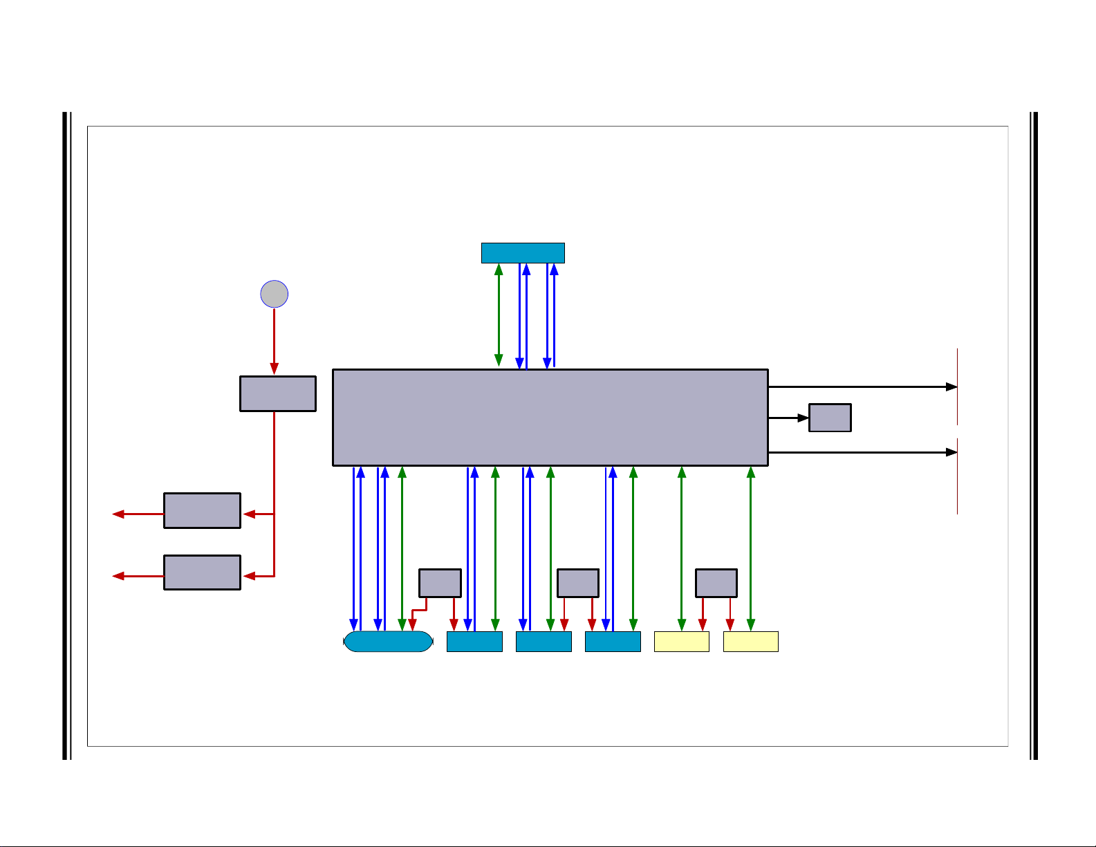
1.3 BLOCK DIAGRAM
Figure 1-1 shows the block diagram of EVB-USB7216.
2
S™ Audio Codec
2
C
DS50002970A-page 10 2020 Microchip Technology Inc.
Page 11
2020 Microchip Technology Inc. DS50002970A-page 11
USB7216
USB Port 0 - MicroB
SPI
Flash
USB3.1
USB2.0
SPI
I2S
+12/24VIN
MCP19035
5.0V
MCP1825
MCP19035
3.3V
1.2V
GPIO/I2C Slave/I2C Master
USB7216 Block Diagram
DS Port 1
DS Port 2
DS Port 3
DS Port 4
DS Port 5 DS Port 6
UCS
2114
UCS
2114
UCS
2114
USB3.1
USB3.1
USB3.1
USB3.1
USB2.0
USB2.0
USB2.0
USB2.0
USB2.0
USB2.0
VBUS
VBU SVBUS
USB3.1
FIGURE 1-1: EVB-USB7216 BLOCK DIAGRAM
Overview
Page 12

EVB-USB7216 Evaluation Kit User’s Guide
1.4 REFERENCES
Concepts and materials available in the following documents may be helpful when
reading this document. Visit www.microchip.com for the latest documentation.
• USB7216 Data Sheet
• AN2810 Configuration of USB7002/USB705x
• AN2932 USB-to-GPIO Bridging with Microchip USB72xx Hubs
• AN2935 Configuration of USB7202/USB7206/USB725x
• AN2936 USB-to-UART Bridging with Microchip USB7202, USB7250, USB7251,
and USB7252 Hubs
• AN3020 USB-to-SPI Bridging with Microchip USB72xx Hubs
• AN3240 USB-to-I
cation Note
1.5 ACRONYMS AND DEFINITIONS
TABLE 1-1: ACRONYMS AND DEFINITIONS
Acronym Definition
BC1.2 Latest USB-IF specified USB battery charging standard
CDP Charging Downstream Port, a BC1.2-compliant port that allows simultane-
DCP Dedicated Charging Port, a BC1.2-compliant port which is only capable of
DFP Downstream Facing Port
EVB Evaluation Board
OTP One-Time Programmable Memory
SDP Standard Downstream Port, a standard USB port with no high-current bat-
SE1 Type of Battery Charging (non-USB compliant) that sets the USB D+/D– to
Type-C Reversible USB Connector
USB-IF USB Integrators Forum, a collection of corporate sponsored members
Gen2 USB Specification 3.2 Gen2
2
C Bridging with Microchip USB720x and USB725x Hubs Appli-
ous USB data and USB charging
USB charging (no data)
tery charging capabilities
specific DC voltages to communicate charging capability
responsible for developing USB specifications
DS50002970A-page 12 2020 Microchip Technology Inc.
Page 13

2.1 INTRODUCTION
The Microchip EVB-USB7216 Evaluation Kit is designed for flexible configuration solutions. It can be configured via default internal register settings, via a downloadable
external firmware to an onboard SPI Flash (OTP memory), via SMBus, or via the
onboard configuration switches. When configured with the default internal register settings, the device operates as a USB 3.2 Gen2 hub with one upstream Gen2 port, one
downstream-facing USB Type-C
stream USB 2.0 ports with Microchip’s standard VID/PID/DID settings.
Microchip provides a comprehensive software programming tool, MPLAB® Connect
Configurator (MPLABCC), for configuring USB7216 functions, registers, and OTP
memory. The USB7216 requires MPLABCC version 2.1.0 or greater.
For additional information on the MPLABCC programming tool, refer to Software
Libraries within the Microchip USB7216 product page at
www.microchip.com/USB7216.
Chapter 2. Getting Started
®
port, three downstream Gen2 ports, and two down-
EVB-USB7216
EVALUATION KIT
USER’S GUIDE
2.2 KIT CONTENTS
The EVB-USB7216 Evaluation Kit includes the basic equipment necessary for evaluation. The items included in the kit are:
• EVB-USB7216 Evaluation Board
• Type-A to Type-uB USB cable
2.3 QUICK START
Perform the following steps to quickly start using the board:
1. Connect a 12V power supply to the barrel connector (J2) or the terminal block
(J4) on the EVB-USB7216.
2. Using a Type-A-to-Type-uB USB cable, connect the EVB-USB7216 to a USB
host via the upstream “Port 0” USB Type-B socket (J3).
Devices may now be connected to any of the downstream ports to enumerate and use
those devices with the USB host.
To perform additional configuration or evaluate specific features, launch the MPLABCC
software on your USB host or manipulate the included hardware configuration options
detailed in the next sections.
2020 Microchip Technology Inc. DS50002970A-page 13
Page 14

EVB-USB7216 Evaluation Kit User’s Guide
NOTES:
DS50002970A-page 14 2020 Microchip Technology Inc.
Page 15

Chapter 3. Hardware Configuration
3.1 HARDWARE CONFIGURATION OPTIONS
Figure 3-1 shows the top view of the EVB-USB7216.
FIGURE 3-1: EVB-USB7216 R1 (TOP VIEW)
EVB-USB7216
EVALUATION KIT
USER’S GUIDE
3.1.1 Configuration
3.1.1.1 EXTERNAL SPI FLASH
Upon power-up, the USB7216 first looks for an external SPI ROM device and a valid
signature in the Flash. If one is found, the external ROM is enabled, and code execution
is initiated from the external SPI ROM device.
To enable operation from the SPI device, install shunts to pins 1 to 2 and 4 to 5 of J18.
When code is executing from an SPI ROM device, a blue LED “SPI-ACTIVE” (D12) illuminates.
Note 1: CFG_BC and CFG_Non-Rem options are deselected when SPI shunts
are installed on J18. When operating in SPI mode, all configuration is
handled by the code executing from the SPI ROM device.
2: If the SPI Flash is not properly programmed or has an invalid signature,
the USB7216 reverts to internal defaults even if the SPI ROM is selected.
2020 Microchip Technology Inc. DS50002970A-page 15
Page 16

EVB-USB7216 Evaluation Kit User’s Guide
3.1.1.2 INTERNAL DEFAULT CONFIGURATIONS WITH STRAPPING OPTIONS
When the USB7216 does not detect a valid SPI Flash image and does not look for
SMBus configuration upon power-up, the USB7216 uses internal default register settings. It also sets the Vendor ID, Product ID, Language ID, and Device ID and additional
settings from the internal ROM code.
If configuration is not done through SPI or SMBus, additional configuration is available
through two functions: CFG_BC_EN and CFG_NON-REM. The controls are configured by selecting one of the six resistor values for each pin. The EVB-USB7216
demonstrates two of the six possible resistor values for each of CFG_BC_EN and
CFG_NON-REM. These straps are sensed by the USB7216 device at power-on to
determine the resultant configuration of the device.
To select the CFG_BC_EN and CFG_NON-REM modes, shunts must be connected to
J16 and J19 headers.
To use the battery charging strap options, connect a shunt to pins 1 to 2 of J8 and connect a shunt to J15 according to Table 3-1. For the NON_REM strap options, connect
a shunt to J19 according to Table 3-2.
TABLE 3-1: BATTERY CHARGING OPTIONS (CFG_BC_EN - J16)
J16 Shunt Position (J12 is shunted pins 2-3.)
2–3 All ports are BC 1.2-disabled.
1–2 All downstream ports are BC1.2-enabled.
TABLE 3-2: NON-REMOVABLE PORT OPTIONS (CFG_NON-REM - J17)
J17 Shunt Position (J12 is shunted pins 5-6.)
2–3 All ports are non-removable.
1–2 All ports are removable.
3.1.2 Power Source – Self Powered
The EVB-USB7216 only supports self-powered operation. Power is supplied through
one +12.0V regulated external power supply. The power supply is connected to the
2.5 mm connector J1 on the board. Alternatively, an external voltage can be supplied
to the screw terminal “12V” (J2). The +12.0V feeds a 15A regulator that outputs +5.2V
(nominal) across the board and also supplies the +3.3V regulator and the 1.2V regulator.
CAUTION
The supplied 12.0V external power supply cannot support simultaneous battery
charging on all downstream ports. Use a higher power supply if the required test use
case exceeds the power capability of the supply. Failure to heed to this warning could
result in damage to the 12.0V external power supply.
3.1.3 Downstream Port Power Control
USB power to the six downstream ports is controlled via port power controllers with
auto-discharge functionality. All downstream ports support BC 1.2 battery charging.
®
The downstream USB Type-C
stream USB Type-A ports are capable of up to 2.1A at 5V.
port is capable of up to 3A of current at 5V. The down-
DS50002970A-page 16 2020 Microchip Technology Inc.
Page 17

Hardware Configuration
3.1.4 USB Type-C® Ports
The USB7216 has two USB3.2 Gen 2 PHYs for the Type-C port. This eliminates the
need for an external multiplexer. The USB7216 also features integrated Type-C control
signal (CC) detection to determine when and in what orientation a USB Type-C
has been made. It powers only the USB3.2 Gen 2 PHY needed for USB communication. To reduce power, the USB7216 powers down unused USB3.2 Gen 1 PHYs. In
cases where no USB Type-C attach is detected, both USB3.2 Gen 1 PHYs associated
with that port are powered down.
3.1.5 LED Indicators
Table 3-3 describes the LED indicators on the EVB-USB7216.
TABLE 3-3: EVB-USB7216 LED INDICATOR DESCRIPTIONS
Ref.
Des.
D1 PORT 0 VBUS Illuminates when 5V to upstream PORT0 VBUS is present
D2 PORT 4 VBUS Illuminates when 5V to upstream PORT4 VBUS is present
D3 A GP Indicator A
D4 F GP Indicator F
D5 E GP Indicator E
D6 B GP Indicator B
D7 C GP Indicator C
D8 D GP Indicator D
D11 RESET The RST_N signal is asserted.
D12 SPI-ACTIVE Indicates SPI Flash Memory activity
D18 5V Illuminates when 5V is present from the 5V voltage regulator
D19 PORT 1 VBUS Illuminates when 5V to upstream PORT1 VBUS is present
D20 3V3 Illuminates when 3.3V is present from the 3.3V voltage regu-
D21 1V2 Illuminates when 1.2V is present from the 3.3V voltage regu-
D22
D23 PORT 2 VBUS Illuminates when 5V to upstream PORT2 VBUS is present
D24 PORT 3 VBUS Illuminates when 5V to upstream PORT3 VBUS is present
D25 PORT 6 VBUS Illuminates when 5V to upstream PORT6 VBUS is present
Label Description
lator
lator
PORT 5 VBUS Illuminates when 5V to upstream PORT5 VBUS is present
®
attach
2020 Microchip Technology Inc. DS50002970A-page 17
Page 18

EVB-USB7216 Evaluation Kit User’s Guide
3.1.6 Switches
Table 3-4 describes the switches on the EVB-USB7216.
TABLE 3-4: EVB-USB7216 SWITCH DESCRIPTIONS
Ref. Des. Label Description
SW2 RESET Momentary push-button switch to assert RST_N
SW1 ON/OFF Connects or disconnects the 12 VDC supply
3.1.7 Connector Descriptions
Table 3-5 describes the connectors included on the PCB.
TABLE 3-5: EVB-USB7216 CONNECTOR DESCRIPTIONS
Ref.
Des.
J1 USB Type-A
J2 Barrel Jack 12VDC 12 VDC supply connection
J3 USB Type-uB
J4 2-pin
J5 6x1 Header — GP indicators for LED drivers
J6 1x1 Header GND Circuit ground
J7 1x1 Header GND Circuit ground
J8 6x2 Header CFG_STRAP Configuration options header
J9 2x1 Header Ext.Reset Connection for an external reset
J10 6x1 Header — Debug header
J11 1x1 Header GND Circuit ground
J12 2x2 Header PF24
J13 1x2 Header HOLD When shunted, this disables the SPI
J14 6x1 Header — Debug header
J15 1x1 Header GND Circuit ground
J16 1x3 Header BC SELECT See Table 3-1.
J18 2x3 Header SPI_DI/CFG_BC_EN
J19 2x3 Header SPI_DI/CFG_BC_EN
Type Label Description
PORT4 Downstream Type-A Gen2 Port 4
Connector
PORT0 Downstream Type-A USB 2.0 Port 0
Connector
— Alternative 12 VDC supply connec-
Terminal
Block
PF23
PF25
PF21
SPI_CEn/CFG_NON_REM
SPI_CEn/CFG_NON_REM
USB connection
(center pin positive)
USB connection
tion. Pin 1 is positive.
switch
SPI data pins provided for debugging
SPI memory
memory.
Selects between SPI memory capability and BC/NON_REM capability.
For SPI, connect pins 1–2 and 4–5.
For BC, connect pins 2–3.
For NON_REM, connect pins 5–6.
Selects between SPI memory capability and BC/NON_REM capability.
For SPI, connect pins 1–2 and 4–5.
For BC, connect pins 2–3.
For NON_REM, connect pins 5–6.
DS50002970A-page 18 2020 Microchip Technology Inc.
Page 19

Hardware Configuration
TABLE 3-5: EVB-USB7216 CONNECTOR DESCRIPTIONS (CONTINUED)
Ref.
Des.
J20 USB
J21 6x1 Header — Debug header
J22 1x1 Header GND Circuit ground
J23 6x1 Header — Debug header
J24 1x1 Header GND Circuit ground
J26 2x2 Header SI2C_CLK
J27 2x2 Header MI2C_CLK
J28 1x1 Header GND Circuit ground
J29 USB Type-A
J30 1x16 Header — Audio Codec Socket
J31 1x3 Header CFG_OPT1
J32 1x2 Header PU Pull-up resistors, Slave I
J33 1x2 Header PU Pull-up resistors, Slave I
J34 1x3 Header — Audio Codec (Spare)
J35 USB Type-A
J36 USB Type-A
J37 USB Type-A
Type Label Description
®
Type-C
Connector
Connector
Connector
Connector
Connector
PORT1 Downstream Type-C Gen2 Port 1
USB connection
2
SI2C_DAT
Hub slave I
Hub master I
MI2C_DAT
PORT5 Downstream Type-A USB 2.0 Port 5
USB connection
CFG_OPTIONS
CFG_OPT2
PORT6 Downstream Type-A USB 2.0 Port 6
USB connection
PORT2 Downstream Type-A Gen2 Port 2
USB connection
PORT3 Downstream Type-A Gen2 Port 3
USB connection
C header
2
C header
2
C
2
C
3.1.8 Test Points
Table 3-6 describes the test points on the EVB-USB7216. A header may be perma-
nently installed on the through-hole test points if needed.
TABLE 3-6: EVB-USB7216 TEST POINT DESCRIPTIONS
Ref. Des. Type Description
TP1 Test Pad PORT4 VBUS
TP2 Test Pad VIN
TP3 Test Loop (Red) 5VL
TP4 Test Loop (Blue) PG5V
TP5 Test Pad DP1 CC2
TP6 Test Pad ATEST 3
TP7 Test Pad ATEST 2
TP8 Test Pad ATEST 1
TP9 Test Pad DP1 CC2
TP10 Test Loop (BLACK) SHDN
TP11 Test Loop (Red) 5V
TP12 Test Loop (Orange) 3V3
TP13 Test Pad PORT1 VBUS
2020 Microchip Technology Inc. DS50002970A-page 19
Page 20

EVB-USB7216 Evaluation Kit User’s Guide
TABLE 3-6: EVB-USB7216 TEST POINT DESCRIPTIONS (CONTINUED)
Ref. Des. Type Description
TP14 Test Loop (Yellow) LVCORE
TP15 Test Pad PORT5 VBUS
TP16 Test Pad PORT2 VBUS
TP17 Test Pad PORT6 VBUS
TP18 Test Pad PORT3 VBUS
DS50002970A-page 20 2020 Microchip Technology Inc.
Page 21

Appendix A. USB7216 Schematics
A.1 INTRODUCTION
This appendix shows the EVB-USB7216 Evaluation Kit schematic.
EVB-USB7216
EVALUATION KIT
USER’S GUIDE
2020 Microchip Technology Inc. DS50002970A-page 21
Page 22

DS50002970A-page 22 2020 Microchip Technology Inc.
FIGURE A-1: EVB-USB7216 BLOCK DIAGRAM
EVB-USB7216 Evaluation Kit User’s Guide
1
2
3
4
5
6
EVB-USB7216
Table of Contents
A A
B B
C C
D D
DescriptionSheet
1
EVB-USB7216
USB7216 Part A
2
USB7216 Part B
3
Memory
4
USB MicroB UFP
5
USB3.1 (Type-C) DFP1
6
USB3.1(Type-A) DFP2-4
7
USB2.0 (Type-A) DFP5-6
8
Voltage Regulators
9
Notes
All resistors are 1% unless specified otherwise1
Shunt jumper default selections are marked
2
with an asterisk [*].
1
3.3V
1.2V
+12/24VIN
MCP19035
5.0V
MCP1825
MCP19035
2
Revision History
1.0 10/02/2019 DevTools Transfer
Revision SummaryRevision Date Author
Block Diagram
US Port 0 - MicroB
USB2.0
USB3.1
USB7216
USB3.1
USB3.1
USB2.0
USB3.1
UCS
2114
DS Port 1 DS Port 2 DS Port 3 DS Port 4 DS Port 5 DS Port 6
3
USB3.1
USB2.0
USB2.0
UCS
2114
VBUS VBUSVBUS
USB3.1
USB2.0
USB2.0
UCS
2114
4
GPIO/I2C Slave/I2C Master
SPI
SPI
Flash
I2S
USB2.0
5
M. Davis
Headers
Headers
Drawn By:
Mick Davis
Engineer:
Mick Davis
Project Title
PartNumber: Variant: [No Variations]
11049
EVB-USB7216
Sheet Title
EVB-USB7216
Size
Tabloid
Revision: Sheet
File:
11049-TOC.SchDoc
03-11049
Sch #: Date:
1.0
1/23/2020 2:44:54 PM
1 of 9
6
Designed with
Altium.com
Page 23

2020 Microchip Technology Inc. DS50002970A-page 23
1
1
2
2
3
3
4
4
5
5
6
6
D D
C C
B B
A A
2 of 9
EVB-USB7216
1/23/2020 2:44:54 PM
11049-USB7216-PartA.SchDoc
Project Title
Sch #: Date:
File:
Revision: Sheet
Designed with
Drawn By:
Mick Davis
Sheet Title
USB7216 Part A
Engineer:
Mick Davis
03-11049
1.0
Size
Tabloid
11049
PartNumber: Variant: [No Variations]
Altium.com
Battery Charging
Non-Removable
BC/Non-Rem Select
CFG_STRAP1
CFG_STRAP1
CFG_STRAP2
SPI_CEn/CFG_NON_REM
SPI_DI/CFG_BC_EN /
OPTION1*
CFG_BC_EN
CFG_NON_REM
For SPI (1-2, 4-5)
For BC (2-3)
Default Open
For NON_REM (5-6)
OPTION2
OPTION3
OPTION4
OPTION5
OPTION6
Connect only one
10k
R90
12k
1%
R70
RBIAS
Reset
Ext. Reset
1k
R41
RESET
RST_N
USB7216 Part A
Reset
SPI_CLK/PF21
4
SPI_MOSI/PF22
4
SPI_MISO/PF23
4
SPI_CE/PF20
4
Configuration Option
*
*
*
SPI_D3/PF25
4
SPI_D2/PF24
4
200k
R28
200k
R27
200k
R82
200k
R76
200k
R77
10k
R30
10k
R31
RST
RST_N
10k
R72
3V3_BRD
200k
R87
CFG_STRAP3
Note to layout: Close spacing between OSC1 and U1A
25 MHz Oscillator
25MHZ
123
J16
123
J19
12345678910
1112
J8
4
213
SPST-NO
SW2
Options 3-6
require custom
firmware
3V3_BRD
3V3_BRD
3V3_BRD
3V3_BRD
3V3_BRD
3V3_BRD
3V3_BRD
3V3_BRD
3V3_BRD
GP_IND_B
GP_IND_C
GP_IND_D
GP_IND_E
LED Drivers
GP_IND_A
GP_IND_F
1
2
3
4
5
6
J5
1k
R7
GP Indicators
GP_IND_A
1k
R13
GP_IND_B
1k
R23
GP_IND_C
1k
R22
GP_IND_D
1k
R17
GP_IND_E
1k
R8
"F"
GP_IND_F
"A"
"B"
"C"
"D"
"E"
D3
D6
D7
D8
D5
D4
3V3_BRD
1 2
Yes
J9
VDD
3
GND
1
RST
2
MIC803/2.93V
U6
1 2
3
5
9
11
13
GND7VCC
14
4
6
8
10
12
1A
2A
3A
4A
5A
6A
1Y
2Y
3Y
4Y
5Y
6Y
74LVC14AD
U2
3V3_BRD
3V3_BRD
0.1uF
C38
0.1uF
C29
0.1uF
C6
0.1uF
C90
0.1uF
C57
0.1uF
C92
0.1uF
C96
0.1uF
C43
0.1uF
C47
0.1uF
C95
0.1uF
C54
0.1uF
C97
0.1uF
C99
0.1uF
C98
0.1uF
C94
0.1uF
C100
0.1uF
C93
0.1uF
C91
0.1uF
C105
0.1uF
C106
2 4
VCC
5
GND
3
VCC
GND
U5
74LVC1G14GW,125
0R
R66
VDDCORE
VDDCORE
RST_N
4
TP8
TP7
TP6
10k
R64
3V3_BRD
10k
R63
3V3_BRD
ATEST1
ATEST2
ATEST3
Select
Select
All Ports BC Enabled [1-2] (10RPU)*
All Ports BC Disabled [2-3] (200k PD)
All Ports Non-Removable [1-2] (10RPU)
All Ports Removeable [2-3] (200k PD)*
XTAL0
25MHZ
VDD33
26
VDD33
43
VDD33
53
VDD33
62
VDD33
67
VDD33
79
VDD33
88
VDD33
99
EP
101
MCLR
63
ICSP_DATA
64
ICSP_CLK
65
SPI_CLK/PF21
68
SPI_D0/CFG_BC_EN/PF22
70
SPI_D1/PF23
71
SPI_CE_N/CFG_NON_REM/PF20
69
SPI_D2/PF24
72
SPI_D3/PF25
73
XTALO
97
XTALI/CLK_IN
98
RESET_N
1
TESTEN
24
RBIAS
100
CFG_STRAP1
21
CFG_STRAP2
22
PowerProgramming
Clock
SPI+SQI
Strap
Utility/Test
ATEST
96
CFG_STRAP3
23
VDD12
9
VDD12
18
VDD12
25
VDD12
31
VDD12
38
VDD12
55
VDD12
78
VDD12
85
VDD12
93
USB7216
U10A
1 2
3
4 5
6
HDR-2.54 Male 3x2
J18
GND2VDD
4
STBY#1OUT
3
GND
V
DD
S
BY#
OUT
Y1
RED
D11
100k
R42
10R
R26
10R
R29
10R
R74
10R
R75
100k
R5
100k
R10
100k
R11
100k
R19
100k
R20
100k
R6
Shunt 2.54mm 1x2 Handle
Default location: J16 1-2
JP1
Shunt 2.54mm 1x2 Handle
Default location: J19 2-3
JP2
Shunt 2.54mm 1x2 Handle
Default location: J8 1-2
JP3
FIGURE A-2: USB7216 PART A
USB7216 Schematics
Page 24

DS50002970A-page 24 2020 Microchip Technology Inc.
1
1
2
2
3
3
4
4
5
5
6
6
D D
C C
B B
A A
3 of 9
EVB-USB7216
1/23/2020 2:44:55 PM
11049-USB7216-PartB.SchDoc
Project Title
Sch #: Date:
File:
Revision: Sheet
Designed with
Drawn By:
Mick Davis
Sheet Title
USB7216 Part B
Engineer:
Mick Davis
03-11049
1.0
Size
Tabloid
11049
PartNumber: Variant: [No Variations]
Altium.com
USB7216 Part B
PU
Default Open
*
10k
R99
10k
R100
SMB/I2C Master
PF4
3, 6
PF5
3, 6
PF8
3, 5
PF9
3, 5
PF10
3, 4
PF11
3, 4
PF13
3, 8
PF15
3, 7
PF16
3, 7
PF17
3, 7
PF6
3
PF7
3, 4
PF12
3
PF14
3, 7
PF18
3, 5
PF19
3, 4
PF26
3, 4
PF27
3, 8
PF28
3, 4, 8
PF29
3, 5
PF30
3, 4
PF31
3, 4
USB2UP_P
5
USB2UP_N
5
USB3UP_TX_P
5
USB3UP_TX_N
5
USB3UP_RX_P
5
USB3UP_RX_N
5
DP1_VBUS_MON
6
DP1_CC1
6
DP1_CC2
6
USB2DN/PRT_DIS_1_P
6
PF6
3
PF7
3, 4
PF5
3, 6
PF4
3, 6
PF8
3, 5
PF9
3, 5
PF10
3, 4
PF11
3, 4
PF12
3
PF13
3, 8
PF14
3, 7
PF15
3, 7
PF16
3, 7
PF17
3, 7
PF18
3, 5
PF19
3, 4
PF26
3, 4
PF27
3, 8
PF28
3, 4, 8
PF29
3, 5
PF30
3, 4
PF31
3, 4
PU
Default Open
*
10k
R113
10k
R112
SMB1CLK
10, 5, 7, 8
SMB1DAT
10, 5, 7, 8
GPIO and SMBUS options
USB2DN/PRT_DIS_1_N
6
USB3DN_TX1A_P
6
USB3DN_TX1A_N
6
USB3DN_RX1A_P
6
USB3DN_RX1A_N
6
USB3DN_TX1B_P
6
USB3DN_TX1B_N
6
USB3DN_RX1B_P
6
USB3DN_RX1B_N
6
USB2DN/PRT_DIS_2_P
7
USB2DN/PRT_DIS_2_N
7
USB3DN_TX2_P
7
USB3DN_TX2_N
7
USB3DN_RX2_P
7
USB3DN_RX2_N
7
USB2DN/PRT_DIS_5_P
8
USB2DN/PRT_DIS_5_N
8
1 2
J33
1 2
J32
1 2
3 4
J27
1 2
3 4
J26
1
2
3
4
5
6
J14
1
2
3
4
5
6
J10
PF3
3, 6
DP1_VCONN2
DP1_VCONN1
DP1_DISCHARGE
GPIO70
*See Config Table
PD_I2C_DATA
PD_I2C_CLK
*See Config Table
*See Config Table
PRT_CTL4_U3
PRT_CTL4
PRT_CTL3
PRT_CTL2
PRT_CTL5
PRT_CTL1
ALERT0
*See Config Table
*See Config Table
*See Config Table
*See Config Table
UPD_RESET_N
USB2DN/PRT_DIS_3_P
7
USB2DN/PRT_DIS_3_N
7
USB3DN_TX3_P
7
USB3DN_TX3_N
7
USB3DN_RX3_P
7
USB3DN_RX3_N
7
USB2DN/PRT_DIS_4_P
7
USB2DN/PRT_DIS_4_N
7
USB3DN_TX4_P
7
USB3DN_TX4_N
7
USB3DN_RX4_P
7
USB3DN_RX4_N
7
SMB/I2C Slave
PF3
3, 6
1
2
3
4
5
6
J21
1
2
3
4
5
6
J23
3V3_BRD
3V3_BRD
Default PF Functions by Configuration Option
OPTION1
PF4
PF5
OPTION2
DP1_VCONN1
PF7
PF8
PF9
PF11
PF12
PF13
PF15
PF16
PF17
PF19
PF20
PF21
PF23
PF24
PF22
PF18
PF14
PF10
PF6
DP1_VCONN2
PF26
PF27
PF28
PF30
PF31
PF29
PF25
DP1_VCONN1
DP1_VCONN2
GPIO70 GPIO70
PD_I2C_DATA
PRT_CTL4_U3
I2S_MCLK
I2S_SDI
PRT_CTL4_U3
PRT_CTL3_U3
PRT_CTL2_U3
I2S_SDO
SPI_CE_N
SPI_CLK
SPI_D0
SPI_D1
SPI_D2
SPI_D3
SLV_I2C_CLK
SLV_I2C_DATA
I2S_SCK
PRT_CTL6
PRT_CTL6
UPD_RESET_N
I2S_LRCK
UPD_RESET_N
MSTR_I2C_CLK
MSTR_I2C_DATA
PF3
GPIO71
DP1_DISCHARGE DP1_DISCHARGE
MIC_DET
PD_I2C_CLK
PD_I2C_DATA
PD_I2C_CLK
PRT_CTL5
PRT_CTL4
PRT_CTL3
PRT_CTL2
PRT_CTL1
ALERT0
PRT_CTL5
PRT_CTL4
PRT_CTL3
PRT_CTL2
PRT_CTL1
ALERT0
SPI_CE_N
SPI_CLK
SPI_D0
SPI_D1
SPI_D2
SPI_D3
GPIO70
GPIO71
GPIO67
GPIO68
Pseudo-OTP Config
GPIO69
GPIO72
GPIO73
GPIO74
GPIO75
GPIO76
GPIO77
GPIO78
GPIO79
GPIO80
GPIO81
GPIO82
GPIO83
GPIO84
GPIO85
GPIO86
GPIO87
GPIO88
GPIO89
GPIO94
GPIO95
GPIO93
GPIO92
GPIO91
GPIO90
1
1
1
2
2
2
2
3
3
3
3
Via OTP/
They may be used only if Downstream Port 1 is
connected to a legacy port(Type-A)
1
They may only be used in special applications where
2
USB Power Delivery is not implemented
Can be used only in special applications where
3
SPI Flash is not utilized
These pins may not be used as GPIOs on this design.
These pins may not be used as GPIOs on this design.
These pins may not be used as GPIOs on this design.
3
3
DP1_VCONN2
DP1_VCONN1
DP1_DISCHARGE
GPIO70
*See Config Table
PD_I2C_DATA
PD_I2C_CLK
*See Config Table
*See Config Table
PRT_CTL5_U3
PRT_CTL4
PRT_CTL3
PRT_CTL2
PRT_CTL5
PRT_CTL1
ALERT0
*See Config Table
*See Config Table
*See Config Table
*See Config Table
UPD_RESET_N
*See Config Table
*See Config Table
MSTR_I2C_CLK
MSTR_I2C_DATA
MSTR_I2C_DAT
MSTR_I2C_CLK
VBUS_DET
5
PF30
3, 4
USB2DN/PRT_DIS_6_P
8
USB2DN/PRT_DIS_6_N
8
0R
R45
0R
R128
USB2DN_DP1/PRT_DIS_P1
5
USB2DN_DM1/PRT_DIS_M1
6
Upstream DS1-TypeC(USB3.1)
DP1_VBUS_MON
4
USB3DN_TXDP1A
7
USB3DN_TXDM1A
8
USB3DN_RXDP1A
10
USB3DN_RXDM1A
11
DP1_CC1
12
DP1_CC2
13
USB2DN_DP5/PRT_DIS_P5
14
USB2DN_DM5/PRT_DIS_M5
15
USB3DN_TXDP1B
16
USB3DN_TXDM1B
17
USB3DN_RXDP1B
19
USB3DN_RXDM1B
20
USB2DN_DP3/PRT_DIS_P3
34
USB2DN_DM3/PRT_DIS_M3
35
USB3DN_TXDP3
36
USB2DN_DP2/PRT_DIS_P2
27
USB2DN_DM2/PRT_DIS_M2
28
USB3DN_TXDM3
37
USB2UP_DP
89
USB2UP_DM
90
VBUS_MON_UP
80
USB3UP_TXDP
91
USB3UP_TXDM
92
USB3UP_RXDP
94
USB3UP_RXDM
95
Program Function
DS2-TypeA(USB3.0)
DS5-TypeA(USB2.0)
PF5
46
PF6
47
PF7
48
PF8
49
PF9
50
PF10
51
PF11
52
PF12
54
PF13
56
PF14
57
PF15
58
PF16
59
PF17
60
PF18
61
PF19
66
PF29
74
PF26
75
PF27
76
PF28
77
PF30
2
PF31
3
PF3
44
PF4
45
USB3DN_RXDP3
39
USB3DN_RXDM3
40
DS3-TypeA(USB3.0)
DS4-TypeA(USB3.0)
DS56-TypeA(USB2.0)
USB3DN_TXDP2
29
USB3DN_TXDM2
30
USB3DN_RXDP2
32
USB3DN_RXDM2
33
USB2DN_DP4/PRT_DIS_P4
81
USB2DN_DM4/PRT_DIS_M4
82
USB3DN_TXDP4
83
USB3DN_TXDM4
84
USB3DN_RXDP4
86
USB3DN_RXDM4
87
USB2DN_DP6/PRT_DIS_P6
42
USB2DN_DM6/PRT_DIS_M6
41
USB7216
U10B
100k
R50
FIGURE A-3: USB7216 PART B
EVB-USB7216 Evaluation Kit User’s Guide
Page 25

2020 Microchip Technology Inc. DS50002970A-page 25
VCC
GND
es
sto
SSS/S
Q
R
49
&
R54D
S
Q
I
43
&
3
op
uate
(
(
DeDefafauu
)
t)
4
4NPS
43&53
op
ulat
e
FIGURE A-4: EVB-USB7216 MEMORY
1
2
3
4
5
6
Memory
A A
B B
SPI Flash
3V3_BRD
R54
10k
Resistor ASSY SPI/SQI
R49 & R54 DNP SQI
R43 & R53 Populate (Default)(Default)
5
R49 & R54
Populate
9&5
DNP
R43 & R53
HOLD
NP
R53
R43
R49
10k
12
J13
C32
0.1uF
t
SPI
I
I2S Codec
3
I2S_MCLK
2
3
I2S_SDI
3
I2S_SDO
3, 8
I2S_LRCK
3
I2S_SCK
3V3_BRD
C C
Layout: Arrange all signals in this block with minimal stubs
0R
0R
U7
8
VDD
7
HOLD/SIO3
3
WP/SIO2
4
VSS
SST26VF016B
J30
1
PF11
2
RST_N
3
PF10
4
PF19
5
PF28
6
PF26
7
I2S HOST
SPI_D2/PF24
SPI_D3/PF25
6
SCK
5
SI/SIO0
2
SO/SIO1
1
CE
I2S_MCLK
RESET
MIC_DET
I2S_SDI
I2S_SDO
I2S_LRCLK
I2S_SCLK
3.3V
GND8GND
2
2
SPARE1
SPARE2
SPARE3
SCL
SDA
5V
16
15
14
13
12
11
10
9
3V3_BRD
R51
100k
R46
10k
PF7
PF30
PF31
5V_BRD
R55
100k
3
MIC_DET
3
MSTR_I2C_CLK
3
MSTR_I2C_DATA
J12
1 2
3 4
Yes
1 - PF24
2 - PF23
3 - PF25
4 - PF21
3V3_BRD
U8
5
VCC
2 4
GND
3
C37
0.1uF
SPI_CE_N
74LVC1G14GW,125
2
SPI_CLK/PF21
2
SPI_MOSI/PF22
2
SPI_MISO/PF23
2
SPI_CE/PF20
D12
1k
R44
BLUE
SPI Flash Active
J34
1
2
3
USB7216 Schematics
3V3_BRD
Drawn By:
D D
1
2
3
4
Mick Davis
Engineer:
Mick Davis
Project Title
PartNumber: Variant: [No Variations]
11049
EVB-USB7216
Sheet Title
Memory
Size
File:
5
Sch #: Date:
Tabloid
Revision: She et
11049-Memory.SchDoc
03-11049
1.0
1/23/2020 2:44:55 PM
4 of 9
6
Designed with
Altium.com
Page 26

DS50002970A-page 26 2020 Microchip Technology Inc.
1
1
2
2
3
3
4
4
5
5
6
6
D D
C C
B B
A A
5 of 9
EVB-USB7216
1/23/2020 2:44:56 PM
11049-USB MicroBUFP.SchDoc
Project Title
Sch #: Date:
File:
Revision: Sheet
Designed with
Drawn By:
Mick Davis
Sheet Title
USB Type-B Upstream Port
Engineer:
Mick Davis
03-11049
1.0
Size
Tabloid
11049
PartNumber: Variant: [No Variations]
Altium.com
PORT0
Upstream USB-B Port
Layout: Place the SS_TX AC coupling capacitors near the USB connector
330R
R1
C_USB3UP_TX_P
C_USB3UP_TX_N
VBUS_UP
43k
R3
49.9k
R4
Note: USB3 Polarity swapped to improve layout
10uF
C5
USB2UP_N
USB2UP_P
USB3UP_TX_P
USB3UP_TX_N
USB3UP_RX_N
USB3UP_RX_P
"Upstream VBUS"
1k
R2
D1
VBUS_DET
EARTH_P0
VBUS
1
GND
5
D-
2
D+
3
VBUS
GND
D
D
Shield
0
SSTX+
7
GND_D
8
SSRX-
9
SSRX+
10
ID
4
SSTX-
6
USB3.0 MICRO-B FEMALE
J3
USB2UP_P
5
USB2UP_N
5
USB3UP_TX_P
5
USB3UP_TX_N
5
USB3UP_RX_P
5
USB3UP_RX_N
5
VBUS_DET
5
TID NO: 360000189
3V3_BRD
0.1uF
C2
3V3_BRD
2 4
VCC
5
GND
3
VCC
GND
U1
0.1uF
C1
0.1uF
C3
0.1uF
C4
USB Type-B Upstream Port
FIGURE A-5: EVB-USB7216 USB TYPE-B UPSTREAM PORT
EVB-USB7216 Evaluation Kit User’s Guide
-
+
Page 27

2020 Microchip Technology Inc. DS50002970A-page 27
VCC
GND
FIGURE A-6: EVB-USB7216 USB TYPE-C® DOWNSTREAM PORT 1
1
2
3
4
5
6
USB3.1 (Type-C) Downstream Port 1
A A
B B
C C
USB-C Downstream Port 1
3
DP1_VBUS_MON
3V3_BRD
2
1
BAV99
3
5V_BRD
3
5V_BRD
PF4
DP1_DISCHARGE
DP1_VCONN1
VBUS1
3V3_BRD
C67
U13
5
VCC
2 4
GND
3
74LVC1G14GW,125
D15
13
SBR160S23
D14
13
SBR160S23
0.1uF
R69
2R
R60
2R
D19
"PORT1 VBUS"
3V3_BRD
R86
1k
Layout:
CC1 and CC2 can be swapped
along with TXA<<>TXB and
RXA<<>>RXB to improve layout
R83
D17
PF5
R59
1k
R71
1k
43k
1%
3
C70
0.1uF
R84
49.9k
1%
CMKDM8005
Q6A
621
R58
1k
3
2
CMKDM8005
Q6B
Q4
2N7002-7-F
354
C46
0.1uF
C45
0.1uF
C40
0.1uF
C42
0.1uF
1
R57
100k
C49
0.1uF
2N7002-7-F
1
R92
100k
Q8
R91
560R
1%
3
2
Layout:
USB3 polarity may
be swapped to
improve layout
Layout:
Place the SS_TX AC coupling
capacitors near the USB connector
If vias are required, place
near the USB connector
3
USB3DN_TX1A_P
3
USB3DN_TX1A_N
3
USB3DN_RX1A_P
3
USB3DN_RX1A_N
3
USB3DN_RX1B_N
3
USB3DN_RX1B_P
3
USB3DN_TX1B_N
3
USB3DN_TX1B_P
3
USB2DN/PRT_DIS_1_P
3
USB2DN/PRT_DIS_1_N
3
DP1_CC1
3
DP1_CC2
C50
0.1uF
C56
0.1uF
C55
C51
0.1uF
C_USB3DN_TXD1B_N
C_USB3DN_TXD1B_P
0.1uF
C_USB3DN_TXD1A_P
C_USB3DN_TXD1A_N
TP9
TP5
TP13
J20
A4
A9
B4
B9
A2
A3
B11
B10
A10
A11
B3
B2
A6
A7
B7
B6
A5
B5
A8
B8
PORT1
VBUS
VBUS
VBUS
VBUS
TX1+
TX1-
RX1+
RX1-
RX2RX2+
TX2TX2+
D+
D-
DD+
GND
CC1
GND
GND
CC2
GND
SBU1
SHLD
SBU2
CON USB3.1 C
TID no: 520000028
A1
A12
R78
330R
EARTH_P1
C60
0.1uF
B1
B12
25
C59
10uF
USB7216 Schematics
C48
R65
0.1uF
1k
3
Q7
2N7002-7-F
3
DP1_VCONN2
D D
1
PF3
1
2
R67
100k
Drawn By:
Mick Davis
Engineer:
3V3_BRD 5V_BRD
EARTH_P1
2
3
VBUS1
4
Mick Davis
Project Title
PartNumber: Variant: [No Variations]
11049
EVB-USB7216
Sheet Title
USB3.1 (Type-C) Downstream Port 1
Size
File:
5
03-11049
Sch #: Date:
Tabloid
1.0
Revision: Sheet
11049-USB-C Downstream 1.SchDoc
1/23/2020 2:44:56 PM
6 of 9
6
Designed with
Altium.com
Page 28

DS50002970A-page 28 2020 Microchip Technology Inc.
1
1
2
2
3
3
4
4
5
5
6
6
D D
C C
B B
A A
7 of 9
EVB-USB7216
1/23/2020 2:44:56 PM
11049-USB-ADownstream 2-4.Sch Doc
Project Title
Sch #: Date:
File:
Revision: Sheet
Designed with
Drawn By:
Mick Davis
Sheet Title
USB3.1 (Type-A) Downstream Ports 2-4
Engineer:
Mick Davis
03-11049
1.0
Size
Tabloid
11049
PartNumber: Variant: [No Variations]
Altium.com
USB3.1 (Type-A) Downstream Ports 2-4
UCS2114 Power Switch For Port1 and Port2
10k
R114
0R
R98
0R
R97
VBUS2
PF17
3
PF15
3
PRT_CTL1 PRT_CTL2
UCS2114 Power Switch For Port3 and Port4
10k
R33
0R
R36
0R
R35
VBUS3 VBUS4
PF14
3
PRT_CTL3
PF13
3
PRT_CTL4
USB2DN/PRT_DIS_2_P
3
USB2DN/PRT_DIS_2_N
3
USB3DN_TX2_P
3
USB3DN_TX2_N
3
USB3DN_RX2_P
3
USB3DN_RX2_N
3
330R
R120
PORT2
USB3.1(Type-A) Downstream Port 2
EARTH_P2
"PORT2 VBUS"
1k
DNP
R133
1k
R121
VBUS2
TP16
C_USB3DN_TX2_N
C_USB3DN_TX2_P
USB2DN/PRT_DIS_3_P
3
USB2DN/PRT_DIS_3_N
3
USB3DN_TX3_P
3
USB3DN_TX3_N
3
USB3DN_RX3_P
3
USB3DN_RX3_N
3
330R
R119
PORT3
USB3.1(Type-A) Downstream Port 3
EARTH_P3
"PORT3 VBUS"
1k
DNP
R134
VBUS3
TP18
C_USB3DN_TX3_N
C_USB3DN_TX3_P
USB3 polarity may
be swapped to
improve layout
USB3 polarity may
be swapped to
improve layout
USB3DN_TX4_P
3
USB3DN_TX4_N
3
USB3DN_RX4_P
3
USB3DN_RX4_N
3
330R
R9
PORT4
USB3.1(Type-A) Downstream Port 4
EARTH_P4
1k
R125
VBUS4
TP1
C_USB3DN_TX4_N
C_USB3DN_TX4_P
USB3 polarity may
be swapped to
improve layout
Layout:
Layout:
Layout:
EARTH_P2
3V3_BRD 5V_BRD
EARTH_P4EARTH_P3
3V3_BRD
3V3_BRD
5V_BRD
5V_BRD
VBUS3
VBUS2
VBUS4
VBUS4VBUS3VBUS2
USB2DN/PRT_DIS_4_P
3
USB2DN/PRT_DIS_4_N
3
VBUS1
VBUS1
5V_BRD
5V_BRD
5V_BRD
5V_BRD
0R
DNP
R110
0R
DNP
R107
0R
DNP
R38
0R
DNP
R39
SMB1CLK
10, 3, 5, 7, 8
SMB1DAT
10, 3, 5, 7, 8
SMB1CLK
10, 3, 5, 7, 8
SMB1DAT
10, 3, 5, 7, 8
0.1uF
C7
0.1uF
C87
0.1uF
C86
0.1uF
C101
0.1uF
C89
0.1uF
C110
0.1uF
C109
0.1uF
C104
2.67A Limit
1k
R123
D23
D24
TID: 360000043
TID: 360000043
VBUS1
1
2
4
7
8
956
3
10
ESD8006
D9
3V3_BRD
"PORT4 VBUS"
1k
R12
D2
3V3_BRD
3V3_BRD
1
2
4
7
8
956
3
10
ESD8006
D13
C_USB3DN_RX4_N
C_USB3DN_RX4_P
Placement: Nearest to USB-AconnectorPlacement: Nearestto USB7216 pins
0.1uF
C107
150uF
16V
C79
Text
47uF
C14
47uF
C12
47uF
C13
47uF
C11
47uF
C74
47uF
C77
47uF
C76
47uF
C78
150uF
16V
C80
150uF
16V
C10
0.1uF
C15
0.1uF
C16
0.1uF
C17
0.1uF
C18
100k
R34
100k
R37
100k
R108
100k
R109
2 4
GND
VCC
3 5
NC7SP17
U19
2 4
GND
VCC
3 5
NC7SP17
U18
2 4
GND
VCC
3 5
NC7SP17
U3
VBUS
1
SSRX-
5
D-
2
D+
3
V
BUS
S
-
D+
Shield
0
SSRX+
6
GND_D
7
SSTX-
8
SSTX+
9
GND
4
J36
VBUS
1
SSRX-
5
D-
2
D+
3
V
B
S
-
Shield
0
SSRX+
6
GND_D
7
SSTX-
8
SSTX+
9
GND
4
J37
VBUS
1
SSRX-
5
D-
2
D+
3
V
B
S
SRX-
D-
Shield
0
SSRX+
6
GND_D
7
SSTX-
8
SSTX+
9
GND
4
J1
TID: 360000043
PWR_EN1
1
GND
2
COMM_ILIM
3
VBUS1
4
VBUS1
5
VS210VS2
9
VDD
8
VS17VS1
6
VBUS2
12
VBUS2
11
BOOST
13
GND
14
PWR_EN2
15
ALERT2
16
GND17SMDATA18SMCLK
19
ALERT1
20
W
R_
EN1
N
COM
_
V
BUS1
V
BUS1
V
2
V
2
BOOS
N
W
R_
EN
A
LERT
2NA
LERT
1
UCS2114
U15
PWR_EN1
1
GND
2
COMM_ILIM
3
VBUS1
4
VBUS1
5
VS210VS2
9
VDD
8
VS17VS1
6
VBUS2
12
VBUS2
11
BOOST
13
GND
14
PWR_EN2
15
ALERT2
16
GND17SMDATA18SMCLK
19
ALERT1
20
P
W
R_
EN1
N
COM
M_ILI
M
V
BUS1
V
BUS1
V
2
V
2
BOOS
T
N
P
W
R_
EN
N
UCS2114
U4
2.67A Limit
27k
1%
R130
27k
1%
R127
FIGURE A-7: EVB-USB7216 USB TYPE-A DOWNSTREAM PORTS 2 TO 4
2
D-
SRX
EVB-USB7216 Evaluation Kit User’s Guide
2
BUS
BUS
2
2
BUS
BUS
US
-
SRX
US
Page 29

2020 Microchip Technology Inc. DS50002970A-page 29
VBUS
G
V
BUS
D
P
W
R_
EN1
N
M
M_ILI
M
V
BUS1
V
BUS1
V
B
V
B
S
TNP
W
R_
EN2
A
LERT
2NA
LERT
1
FIGURE A-8: EVB-USB7216 USB TYPE-A DOWNSTREAM PORTS 5 TO 6
1
2
3
4
5
6
USB2.0 (Type-A) Downstream Ports 5-6
A A
UCS2114 Power Switch For Port5 and Port6
C108
3V3_BRD
C85
C83
R111
10k
B B
0R
R102
3, 7
PF16
PRT_CTL5
VBUS5
10, 3, 5, 7
SMB1DAT
10, 3, 5, 7
SMB1CLK
C C
5V_BRD
0.1uF
47uF
47uF
13
20
1
4
5
R106
R103
6
BOOST
BOO
ALERT1
PWR_EN1
VBUS1
VBUS1
2
DNP
DNP
VS17VS1
GND
GND17SMDATA18SMCLK
14
0R
0R
5V_BRD5V_BRD
8
VDD
COMM_ILIM
CO
PWR_EN2
GND
19
9
ALERT2
VBUS2
VBUS2
R105
R104
C82
47uF
C84
U16
UCS2114
VS210VS2
3
16
15
12
US2
11
US2
2.1A Limit
PF27/28
VBUS6
CFG_STRAP
OPTION1: 1-2
3
PF27
3, 4
PF28
CFG_STRAP
OPTION2: 2-3
100k
100k
R131
22k
1%
1
2
3
J31
USB-A Downstream Port 5
VBUS5
3
USB2DN/PRT_DIS_5_N
3
USB2DN/PRT_DIS_5_P
3V3_BRD47uF
U14
VCC
2 4
GND
USB-A Downstream Port 6
VBUS6
3
USB2DN/PRT_DIS_6_N
3
USB2DN/PRT_DIS_6_P
3V3_BRD
U17
VCC
2 4
GND
3 5
3 5
VBUS5
NC7SP17
VBUS6
NC7SP17
"PORT5 VBUS"
D22
"PORT6 VBUS"
D25
R101
R122
TP15
R116
1k
DNP
1k
TP17
R117
1k
DNP
1k
C72
150uF
16V
C81
150uF
16V
C102
C88
2
3
4
1%
1
R115
2
3
4
1%
1
R118
VBUS
D-
D+
GND
GND
J29
+
VBUS
D-
D+
GND
0.1uF
J35
0
330R
EARTH_P5
+
ND
0
330R
0.1uF
EARTH_P6
PORT5
292303-1
TID: 360000089
USB2.0 STD-A FEMALE
PORT6
292303-1
TID: 360000089
USB2.0 STD-A FEMALE
USB7216 Schematics
VBUS5 VBUS6
D D
1
2
3
4
3V3_BRD 5V_BR D
EARTH_P5 EARTH_P6
Drawn By:
Mick Davis
Engineer:
Mick Davis
Project Title
PartNumber: Variant: [No Variations]
11049
EVB-USB7216
Sheet Title
USB2.0 (Type-A) Downstream Ports 5-6
Size
File:
5
03-11049
Sch #: Date:
Tabloid
1.0
Revision: Sheet
11049-USB-ADownstream 5-6.Sch Doc
1/23/2020 2:44:57 PM
8 of 9
6
Designed with
Altium.com
Page 30

DS50002970A-page 30 2020 Microchip Technology Inc.
1
1
2
2
3
3
4
4
5
5
6
6
D D
C C
B B
A A
9 of 9
EVB-USB7216
1/23/2020 2:44:58 PM
11049-Voltage_Regulators.SchDoc
Project Title
Sch #: Date:
File:
Revision: Sheet
Designed with
Drawn By:
Mick Davis
Sheet Title
Voltage Regulators
Engineer:
Mick Davis
03-11049
1.0
Size
Tabloid
11049
PartNumber: Variant: [No Variations]
Altium.com
Fiducials
Mounting Holes
VIN12V to 5VDC
Change Rfb2 to change voltage:
2.6k = 5.25V
2.7k = 5V
2.9k = 4.75V
Rfb2 = (0.6 * Rfb1) / (Vout - 0.6)
Voltage Regulators
10k
R79
5V_BRD
3V3_BRD
1k
R95
3V3
3V3 @ 500mA
10uF
C61
12k
R81
10uF
C63
5VDC to 3.3VDC
3V3
GND
86.6k
R80
MH1
FID5 FID3 FID6
FID2 FID1 FID4
MH2 MH3 MH4
5VDC to 1.2-1.1VDC (VDDCORE Voltage)
5V @ 15A
20k
R61
750R
R68
680pF
C44
5V_BRD
33pF
C35
3900pF
C34
8.2k
R56
140k
R48
VIN
5V
FB5V
5VL
PG5V
5V
20R
R25
2.2k
R88
Rfb2
Rfb1
VIN
10k
R85
10k
R89
470pF
C71
22uF
C62
2.2uF
C66
22uF
C75
1V2
1.15V @ 2A
D10
J7
12VDC
1k
DNP
R32
D21
D20
D18
3V3_BRD
VDDCORE
5V_BRD
3V3_BRD5V_BRDVIN
L1V
FB_VDDCORE
FB3V3
FB3V3
L5V
L5V
VIN_SW
TP LOOP Red
TP2
TP LOOP Red
TP11
TP LOOP Red
DNP
TP3
TP LOOP Black
TP10
TP LOOP Yellow
TP14
4.7uF
35V
C30
TP LOOP BLUE
DNP
TP4
2
1
J4
TP LOOP Orange
TP12
3V3_BRD
VIN
4
SHDN
1
+VCC
6
PWRGD
5
EP
11
FB
2
COMP
3
LDRV
7
BOOT
8
PHASE
9
HDRV
10
MCP19035
U9
GND (TAB)
6
VIN2VOUT
4
GND
3
SHDN
1
ADJ
5
MCP1825/ADJ
U11
SS
6
FB
4
EN
2
SNS
3
VIN
9
S
S
EN
SNS
V
N
AGND
7
PG
5
EP
11
PGND
10
SW
1
SVIN
8
MIC23201
U12
1.5uH
L2
1
3
2
MMBT3904
Q9
0.1uF
C22
0.1uF
C41
0.1uF
C69
0.1uF
C58
0.1uF
C68
0.1uF
C64
0.1uF
C73
0.33uF
C33
0R
R47
2uH
L1
100uF
10V
C65
100uF
10V
C53
100uF
10V
C52
SMBJP6KE6.8
D16
Set for 5.3V output
VDDCORE
L1V FB_VDDCORE
0R
R73
J11 J15 J22 J24 J28 J6
14k
0603
1%
R94
14K = 1.15V
1
2
3
2.5mm
12V (typ)
BARREL JACK
J2
14.7K
0603
1%
R52
ON
OFF
VIN_SW
0.1uF
C8
3
122N7002-7-F
Q1
20k
0603
5%
R15
10k
R16
10k
R124
10k
R24
10k
R21
2
3 1
SPDT
SW1
1uF
C103
3
4
1,2,5,6
AO6405
Q2
VIN
VIN_SW_PREFUSE
Slow 7A
2-SMD
F1
VIN_SW_PREFUSE
10pF
C9
10uF
35V
C19
10uF
35V
C20
10uF
35V
C21
10uF
35V
C23
10uF
35V
C24
10uF
35V
C25
10uF
35V
C26
10uF
35V
C28
10uF
35V
C27
10uF
35V
C31
10uF
35V
C36
10uF
35V
C39
20R
R18
4.7k
R14
499R
R93
12k
R96
100k
R40
2.55k
0603
R62
3
4
1,2,5,6
AO6405
Q10
3
4
1,2,5,6
AO6405
Q11
4
1,2,3
5,6,7,8
SiRA24DP
Q3
4
1,2,3
5,6,7,8
SiRA12BDP
Q5
LABEL Need Help Small
LABEL1
RUBBER PAD D8H2.8
PAD1
PAD2 PAD3 PAD4
FIGURE A-9: EVB-USB7216 VOLTAGE REGULATORS
EVB-USB7216 Evaluation Kit User’s Guide
Page 31

EVB-USB7216
EVALUATION KIT
USER’S GUIDE
Appendix B. Bill of Materials
B.1 INTRODUCTION
This appendix contains the EVB-USB7216 Evaluation Board Bill of Materials (BOM).
2020 Microchip Technology Inc. DS50002970A-page 31
Page 32

DS50002970A-page 32 2020 Microchip Technology Inc.
EVB-USB7216 Evaluation Kit User’s Guide
TABLE B-1: EVB-USB7216 BILL OF MATERIALS
Item Quantity Designator Description Populated Manufacturer Manufacturer Part Number
1 63 C1, C2, C3, C4, C6, C7,
2 4 C5, C59, C61, C63 CAP CER 10 µF 16V 10% X5R SMD 0805 Yes Wurth Electronics Inc 885012107014
3 1 C9 CAP CER 10 pF 50V 5% NP0 SMD 0402 Yes Murata GRM1555C1H100JZ01D
4 5 C10, C72, C79, C80, C81 CAP ALU 150 µF 16V 20% SMD D8 Yes Panasonic Electronic Components EEE-FPC151XAP
5 12 C11, C12, C13, C14, C74,
6 12 C19, C20, C21, C23, C24,
7 1 C30 CAP CER 4.7 µF 35V 10% X7R SMD 0805 Yes TDK Corporation C2012X7R1V475K125AE
8 1 C33 CAP CER 0.33 µF 50V 10% X7R SMD 0805 Yes TDK Corporation CGJ4J2X7R1H334K125AA
9 1 C34 CAP CER 3900 pF 50V
10 1 C35 CAP CER 33 pF 50V 5% NP0 SMD 0603 Yes KEMET C0603C330J5GACTU
11 1 C44 CAP CER 680 pF 50V 5% NP0 SMD 0603 Yes Panasonic ECJ-1VC1H681J
12 3 C52, C53, C65 CAP CER 100 µF 10V 20% X5R SMD 1210 Yes Murata Electronics North America GRM32ER61A107ME20L
13 2 C62, C75 CAP CER 22 µF 10V 10% X7R SMD 1206 Yes Samsung Electro-Mechanics America,
14 1 C66 CAP CER 2
15 1 C71 CAP CER 470 pF 25V 5% NP0 SMD 0603 Yes AVX 06033A471JAT2A
16 1 C103 CAP CER 1 µF 16V 10% X5R SMD 0402 Yes Murata GRM155R61C105KE01D
17 16 D1, D2, D3, D4, D5, D6,
18 2 D9, D13 DIO TVS ESD8006MUTAG 3.3V SMD UDFN-8 Yes ON Semiconductor ESD8006M
19 1 D10 DIO RECT MMBD914-7-F 1.25V 200 mA 75V SMD SOT-23-3 Yes Diodes Incorporated MMBD914-7-F
C8, C15, C16, C17, C18,
C22, C29, C32, C37, C38,
C40, C41, C42, C43, C45,
C46, C47, C48, C49, C50,
C51, C54, C55, C56, C57,
C58, C60, C64, C67, C68,
C69, C70, C73, C86, C87,
C88, C89, C90, C91, C92,
C93, C94, C95, C96, C97,
C98, C99, C100, C101,
C10
2, C104, C105, C106,
C107, C108, C109, C110
6, C77, C78, C82, C83,
C7
C84, C85
C25, C26, C27, C28, C31,
C36, C39
D7, D8, D18, D19, D20,
D21, D22, D23, D24, D25
CAP CER 0.1 µF 35V 10% X7R SMD 0402 Yes TDK Corporation CGA2B3X7R1V104K050BB
CAP CER 47 µF 6.3V 20% X5R SMD 0805 Yes Taiyo Yuden JMK212BJ476MG-T
CAP CER 10 µF 35V 10% X5R SMD 1206 Yes Taiyo Yuden GMK316BJ106KL-T
5% C0G SMD 0603 Yes TDK Corporation C1608C0G1H392J080AA
CL31B226KPHNNNE
Inc
.2 µF 10V 10% X7R SMD 0603 Yes Taiyo Yuden LMK107B7225KA-T
DIO LED GREEN 2V 30 mA 35 mcd Clear SMD 0603 Yes Lite-On Inc LTST-C191KGKT
UTAG
Page 33

2020 Microchip Technology Inc. DS50002970A-page 33
TABLE B-1: EVB-USB7216 BILL OF MATERIALS (CONTINUED)
Item Quantity Designator Description Populated Manufacturer Manufacturer Part Number
20 1 D11 DIO RED 2V 20 mA 54 mcd CLEAR SMD 0603 Yes Lite-On Inc. LTST-C191KRKT
21 1 D12 DIO LED BLUE 2.8V 20 mA 15 mcd Clear SMD 0603 Yes Lite-On LTST-C193TBKT-5A
22 2 D14, D15 DIO SBAR SBR160S23-7 SBR 530 mV 900 mA 60V SMD SOT23-3 Yes Diodes Incorporated SBR160S23-7
23 1 D16 DIO TVS SMBJP6KE6.8CA 5.8V 600W DO-214AA_SMB Yes Micro Commercial Co SMBJP6KE6.8CA-TP
24 1 D17 DIO RECTARR BAV99 1.25V 200 mA 70V SOT-23-3 Yes Fairch
25 1 F1 RES FUSE 7A 72VAC 60VDC SLOW 2-SMD Yes Littelfuse Inc. 0154007.DRT
26 3 J1, J36, J37 CON USB3.0 STD-A FEMALE TH R/A Yes Wurth Electronics Inc 692121030100
27 1 J2 CON JACK Power Barrel Black Male TH RA Yes CUI Inc. PJ-002BH
28 1 J3 CON USB3.0 MICRO-B FEMALE SMD R/A Yes Hirose Electric Co Ltd ZX360D-B-10P
29 1 J4 CON TERMINAL 5.08 mm 1X2 Female 16-30 AWG 13.5A TH RA Yes TE Connectivity 282836-2
30 5 J5, J10, J14, J21,
31 6 J6, J11, J15, J22, J24, J28 CON HDR-2.54 Male 1x1 Gold 5.84 MH TH VERT Yes Samtec Inc. TSW-101-07-S-S
32 1 J7 CON HDR-2.54 Male 1x1 Gold 5.84 MH TH VERT Yes TE Connectivity 5-146280-1
33 1 J8 CON HDR-2.54 Male 2x6 Gold 5.84 MH TH VERT Yes Samtec TSW-106-07-G-D
34 4 J9, J13, J32, J33 CON HDR-2.54 Male 1x2 Gold 5.84 MH TH VERT Yes FCI 77311-118-02LF
35 3 J12, J2
36 4 J16, J19, J31, J34 CON HDR-2.54 Male 1x3 Gold 5.84 MH TH VERT Yes FCI 68000-103HLF
37 1 J18 CON HDR-2.54 Male 3x2 Gold 5.84 MH TH VERT Yes Samtec Inc. TSW-102-07-G-T
38 1 J20 CON USB3.0 TYPE-C FEMALE SMD R/A Yes Advanced-Connectek Inc. NBR25-AK5322
39 2 J29, J35 CON USB2.0 STD-A FEMALE TH R/A Yes TE Connectivity AMP Connectors 292303-1
6, J27 CON HDR-2.54 Male 2x2 Gold 5.84 MH TH VERT Yes Samtec TSW-102-07-G-D
J23 CON HDR-2.54 Male 1x6 Tin 5.84 MH TH VERT Yes Sullins PEC06SAAN
ild BAV99
40 2 J30
41 3 JP1, JP2, JP3 MECH HW JUMPER 2.54 mm 1x2 w/ Handle MECH TE Connectivity AMP Connectors 880584-4
42 1 L1 INDUCTOR 2 µH 23A 20% SMD L12.8W12.8H6.2 Yes Wurth Electronics Inc. 7443551200
43 1 L2 INDUCTOR 1.5 µH 3A 20% SMD L5W5H2.2 Yes Murata Electronics North America LQH5BPN1R5NT0L
44 1 LABEL1 LABEL, ASSY W/REV LEVEL (SMALL MODULES) PER MTS-0002 MECH
45 4 PAD1, P
46 4 Q1, Q4, Q7, Q8 TRANS FET N-CH 2N7002-7-F 60V 170 mA 370 mW SOT-23-3 Yes Diodes Inc 2N7002-7-F
47 3 Q2, Q10, Q11 TRANS FET P-CH AO6405 30V 5A 0.052R 2W TSOP-6 Yes Alpha & Omega Semiconductor Inc AO6405
48 1 Q3 TRANS FET N-CH SiRA24DP-T1-GE3 25V 60A 62.5W PPAK SO-8 Yes Vishay / Siliconix SIRA24DP-T1-GE3
49 1 Q5 TRANS FET N-CH SiRA12BDP
AD2, PAD3,
PAD4
SOCKET I
MECH HW RUBBER PAD Cylindrical flat top D8H2.8 Black MECH 3M SJ5076BLACK
2
S™ HOST DIP 16 TH
-T1-GE3 30V 60A 38W PPAK SO-8 Yes Vishay Siliconix SIRA12BDP-T1-GE3
Yes Sullins Connector Solutions PPTC081LFBN-RC
Bill of Materials
Page 34

DS50002970A-page 34 2020 Microchip Technology Inc.
TABLE B-1: EVB-USB7216 BILL OF MATERIALS (CONTINUED)
Item Quantity Designator Description Populated Manufacturer Manufacturer Part Number
50 1 Q6 TRANS FET DUAL P+P CMKDM8005 20V 650 mA 360R 0.350W
51 1 Q9 TRANS BJT NPN MMBT3904 40V 200 mA 310 mW SOT-23-3 Yes Diodes Incorporated MMBT3904-7
52 7 R1, R9, R78, R115, R118,
R119, R120
53 21 R2, R7, R8, R12, R13,
R17, R22, R23, R41, R44,
R58, R59, R65, R71, R86,
R95, R101, R121, R122,
R123, R125
54 2 R3, R83 RES TKF 43k 1% 1/10W SMD 0603 Yes Yageo 9C06031A4302FKHFT
55 2 R4, R84 RES TKF 49.9k 1% 1/10W SMD 0603 Yes Panasonic ERJ-3EKF4992V
56 20 R5, R6, R10, R11, R19,
R20, R34, R37, R40, R42,
R50, R51, R55, R57, R67,
R92, R104, R105, R108,
R109
57 1 R14 RES TF 4.7k 0.5% 1/10W SMD 0603 Yes Yageo RT0603DRD07
58 1 R15 RES TKF 20k 5% 1/10W SMD 0603 Yes Panasonic ERJ-3GSYJ203
59 23 R16, R21, R24, R30, R31,
R33, R46, R49, R54, R63,
R64, R72, R79, R85, R89,
R90, R99, R100, R111,
R112, R113, R114, R124
60 2 R18, R25 RES TKF 20R 1% 1/10W SMD 0603 Yes Panasonic ERJ-3EKF20R0V
61 4 R26, R29, R74, R75 RES TKF 10R 5% 1/10W SMD 0603 Yes Panasonic ERJ-3GSYJ100V
62 6 R27, R28, R76, R77, R
R87
63 5 R32, R116, R117, R133,
R134
64 12 R35, R36, R43, R45, R47,
R53, R66, R73, R97, R98,
R102, R128
65 6 R38, R39, R103, R106,
R107, R110
66 1 R48 RES TKF 140k 1% 1/10W SMD 0603 Yes Panasonic ERJ-3EKF
67 1 R52 RES TKF 14.7K 1% 1/10W SMD 0603 Yes Panasonic Electronic Components ERJ-3EKF1472V
68 1 R56 RES TKF 8.2k 1% 1/10W SMD 0603 Yes Panasonic ERJ-3EKF8201V
69 2 R60, R69 RES TKF 2R 1% 1/4W SMD 0603 Yes Vishay Dale CRCW06032R00FKEAHP
70 1 R61 RES TKF 20k 1% 1/10W SMD 0603 Yes Panasonic ERJ-3EKF2002V
SOT-363
RES TKF 330R 1% 1/10W SMD 0603 Yes Panasonic ERJ-3EKF3300V
RES TKF 1k 1% 1/10W SMD 0603 Yes Panasonic ERJ-3EKF1001V
RES TKF 100k 1% 1/10W SMD 0603 YES TE Connectivity 1622827-1
RES TKF 10k 1% 1/10W SMD 0603 Yes ROHM MCR03EZPFX1002
82,
RES TKF 200k 1% 1/10W SMD 0603 Yes Panasonic ERJ-3EKF2003V
RES TKF 1k 1% 1/10W SMD 0603 DNP Panasonic ERJ-3EKF1001V
RES TKF 0R 1/10W SMD 0603 Yes Panasonic ERJ-3GSY0R00V
RES TKF 0R 1/10W SMD 0603 DNP Panasonic ERJ-3GSY0R00V
Yes Central Semiconductor Corp CMKDM8005 TR
4K7L
1403V
EVB-USB7216 Evaluation Kit User’s Guide
Page 35

2020 Microchip Technology Inc. DS50002970A-page 35
TABLE B-1: EVB-USB7216 BILL OF MATERIALS (CONTINUED)
Item Quantity Designator Description Populated Manufacturer Manufacturer Part Number
71 1 R62 RES TKF 2.55k 1% 1/10W SMD 0603 Yes Yageo RC0603FR-072K55L
72 1 R68 RES TKF 750R 1% 1/10W SMD 0603 Yes Vishay CRCW0603750RFKEA
73 3 R70, R81, R96 RES TKF 12k 1% 1/10W SMD 0603 Yes Yageo RC0603FR-0712KL
74 1 R80 RES TKF 86.6k 1% 1/10W SMD 0603 Yes Panasonic Electronic Components ERJ-3EKF8662V
75 1 R88 RES TKF 2.2k 1% 1/10W SMD 0603 Yes Panasonic ERJ-3EKF2201V
76 1 R91 RES TKF 560R 1% 1/10W SMD 0603 Yes Yageo RC0603FR-07560
77 1 R93 RES TKF 499R 1% 1/10W SMD 0603 Yes KOA Speer RK73H1JTTD4990F
78 1 R94 RES TKF 14k 1% 1/10W SMD 0603 AEC-Q200 Yes Panasonic Electronic Components ERJ-3EKF1402V
79 2 R127, R130 RES TKF 27k 1% 1/10W SMD 0603 Yes Yageo RC0603FR-0727KL
80 1 R131 RES TKF 22k 1% 1/10W SMD 0603 Yes Panasonic ERJ-3EKF2202V
81 1 SW1 SWITCH SLIDE SPDT 120V 6A 1101M2S3CQE2 TH Yes C&K Components 1101M2S3CQE2
82 1 SW2 SWITCH TACT SPST 16V 50 mA PTS810 SJ
83 2 TP2, TP11 MISC, TEST POINT MULTI PURPOSE MINI RED Yes Keystone 5000
84 1 TP3 MISC, TEST POINT MULTI PURPOSE MINI RED DNP Keystone 5000
85 1 TP4 CON TP LOOP BLUE Ag TH DNP Keystone Electronics 5117
86 1 TP10 MISC, TEST POINT MULTI PURPOSE MINI BLACK Yes Keystone 5001
87 1 TP12 CON TP LOOP Orange TH Yes Keystone Electronics 5003
88 1 TP14 MISC, TEST POINT PC MINI, 0.040" D Y
89 4 U1, U5, U8, U13 74LVC1G14GW,125 SCHMITT-TRG INVERTER Yes NXP 74LVC1G14GW,125
90 1 U2 IC BUFFER 74LVC14AD,118 SOIC-14 Yes Nexperia USA Inc. 74LVC14AD,118
91 5 U3, U14, U17, U18, U19 IC BUFFER NC7SP17 SC-70-5 Yes Fairchild Semiconductor NC7SP17P5X
92 3 U4, U15, U16 MCHP INTERFACE USB Power Controller UCS2114 QFN-20 Yes Microchip Technology Inc. UCS2114-1-V/LX
93 1 U6 MCHP ANALOG SUPERVISOR 2.93V MIC803-2
94 1 U7 MCHP MEMORY SERIAL FLASH 16M 104 MHz
95 1 U9 MCHP ANALOG PWM CONTROLLER 600 kHz
96 1 U10 MCHP INTERFACE USB 3.1 TYPE-C HUB CTLR QFN-100 Yes Microchip Technology Inc. USB7216
97 1 U11 MCHP ANALOG LDO ADJ
98 1 U12 MCHP ANALOG SWITCHER Buck 0.95V to 3.6V 2A
99 1 Y1 MCHP CLOCK OSCILLATOR SINGLE 25 MHZ
SMD
SOT-23-3
SST26VF016B-104I/SM SOIJ-8
MCP19035-BAABE/MF DFN-10
MCP1825T-ADJE/DC SOT-223-5 Yes Microchip Technology Inc. MCP1825T-ADJE/DC
MIC23201YML-TR MLF-10
DSC1001CI2-025.0000 CDFN-4
M 250 SMTR LFS
ELLOW Yes Keystone 5004
9D4VM3-TR
Yes C&K Components PTS810 SJM 250 SMTR LFS
Yes Microchip Technology Inc. MIC803-29D4VM3-TR
Yes Microchip Technology Inc. SST26VF016B-104I/SM
Yes Microchip Technology Inc. MCP19035-BAABE/MF
Yes Microchip Technology Inc. MIC23201YML-TR
Yes Microchip Technology Inc. DSC1001CI2-025.0000
RL
Bill of Materials
Page 36

EVB-USB7216 Evaluation Kit User’s Guide
NOTES:
DS50002970A-page 36 2020 Microchip Technology Inc.
Page 37

EVB-USB7216
EVALUATION KIT
USER’S GUIDE
Appendix C. PCB Silk Screens
C.1 INTRODUCTION
This appendix shows the top and bottom silk screen images of the EVB-USB7216 PCB.
2020 Microchip Technology Inc. DS50002970A-page 37
Page 38

EVB-USB7216 Evaluation Kit User’s Guide
FIGURE C-1: EVB-USB7216 TOP SILK SCREEN IMAGE
DS50002970A-page 38 2020 Microchip Technology Inc.
Page 39

FIGURE C-2: EVB-USB7216 BOTTOM SILK SCREEN IMAGE
PCB Silk Screens
2020 Microchip Technology Inc. DS50002970A-page 39
Page 40

Worldwide Sales and Service
AMERICAS
Corporate Office
2355 West Chandler Blvd.
Chandler, AZ 85224-6199
Tel: 480-792-7200
Fax: 480-792-7277
Technical Support:
http://www.microchip.com/
support
Web Address:
www.microchip.com
Atlanta
Duluth, GA
Tel: 678-957-9614
Fax: 678-957-1455
Austin, TX
Tel: 512-257-3370
Boston
Westborough, MA
Tel: 774-760-0087
Fax: 774-760-0088
Chicago
Itasca, IL
Tel: 630-285-0071
Fax: 630-285-0075
Dallas
Addison, TX
Tel: 972-818-7423
Fax: 972-818-2924
Detroit
Novi, MI
Tel: 248-848-4000
Houston, TX
Tel: 281-894-5983
Indianapolis
Noblesville, IN
Tel: 317-773-8323
Fax: 317-773-5453
Tel: 317-536-2380
Los Angeles
Mission Viejo, CA
Tel: 949-462-9523
Fax: 949-462-9608
Tel: 951-273-7800
Raleigh, NC
Tel: 919-844-7510
New York, NY
Tel: 631-435-6000
San Jose, CA
Tel: 408-735-9110
Tel: 408-436-4270
Canada - Toronto
Tel: 905-695-1980
Fax: 905-695-2078
ASIA/PACIFIC
Australia - Sydney
Tel: 61-2-9868-6733
China - Beijing
Tel: 86-10-8569-7000
China - Chengdu
Tel: 86-28-8665-5511
China - Chongqing
Tel: 86-23-8980-9588
China - Dongguan
Tel: 86-769-8702-9880
China - Guangzhou
Tel: 86-20-8755-8029
China - Hangzhou
Tel: 86-571-8792-8115
China - Hong Kong SAR
Tel: 852-2943-5100
China - Nanjing
Tel: 86-25-8473-2460
China - Qingdao
Tel: 86-532-8502-7355
China - Shanghai
Tel: 86-21-3326-8000
China - Shenyang
Tel: 86-24-2334-2829
China - Shenzhen
Tel: 86-755-8864-2200
China - Suzhou
Tel: 86-186-6233-1526
China - Wuhan
Tel: 86-27-5980-5300
China - Xian
Tel: 86-29-8833-7252
China - Xiamen
Tel: 86-592-2388138
China - Zhuhai
Tel: 86-756-3210040
ASIA/PACIFIC
India - Bangalore
Tel: 91-80-3090-4444
India - New Delhi
Tel: 91-11-4160-8631
India - Pune
Tel: 91-20-4121-0141
Japan - Osaka
Tel: 81-6-6152-7160
Japan - Tokyo
Tel: 81-3-6880- 3770
Korea - Daegu
Tel: 82-53-744-4301
Korea - Seoul
Tel: 82-2-554-7200
Malaysia - Kuala Lumpur
Tel: 60-3-7651-7906
Malaysia - Penang
Tel: 60-4-227-8870
Philippines - Manila
Tel: 63-2-634-9065
Singapore
Tel: 65-6334-8870
Taiwan - Hsin Chu
Tel: 886-3-577-8366
Taiwan - Kaohsiung
Tel: 886-7-213-7830
Taiwan - Taipei
Tel: 886-2-2508-8600
Thailand - Bangkok
Tel: 66-2-694-1351
Vietnam - Ho Chi Minh
Tel: 84-28-5448-2100
EUROPE
Austria - Wels
Tel: 43-7242-2244-39
Fax: 43-7242-2244-393
Denmark - Copenhagen
Tel: 45-4450-2828
Fax: 45-4485-2829
Finland - Espoo
Tel: 358-9-4520-820
France - Paris
Tel: 33-1-69-53-63-20
Fax: 33-1-69-30-90-79
Germany - Garching
Tel: 49-8931-9700
Germany - Haan
Tel: 49-2129-3766400
Germany - Heilbronn
Tel: 49-7131-72400
Germany - Karlsruhe
Tel: 49-721-625370
Germany - Munich
Tel: 49-89-627-144-0
Fax: 49-89-627-144-44
Germany - Rosenheim
Tel: 49-8031-354-560
Israel - Ra’anana
Tel: 972-9-744-7705
Italy - Milan
Tel: 39-0331-742611
Fax: 39-0331-466781
Italy - Padova
Tel: 39-049-7625286
Netherlands - Drunen
Tel: 31-416-690399
Fax: 31-416-690340
Norway - Trondheim
Tel: 47-7288-4388
Poland - Warsaw
Tel: 48-22-3325737
Romania - Bucharest
Tel: 40-21-407-87-50
Spain - Madrid
Tel: 34-91-708-08-90
Fax: 34-91-708-08-91
Sweden - Gothenberg
Tel: 46-31-704-60-40
Sweden - Stockholm
Tel: 46-8-5090-4654
UK - Wokingham
Tel: 44-118-921-5800
Fax: 44-118-921-5820
DS50002970A-page 40 2020 Microchip Technology Inc.
05/14/19
 Loading...