

Page 1

AVR-IoT WA User Guide
AVR-IoT WA Development Board User Guide
Preface
Introduction
The AVR-IoT WA Development Board is a small and easily expandable demonstration and development platform for
IoT solutions. Based on the AVR® microcontroller architecture and using Wi-Fi® technology, it is designed to
demonstrate that the design of a typical IoT application can be simplified by partitioning the problem into three blocks:
• Smart – represented by the ATmega4808 microcontroller
• Secure – represented by the ATECC608A secure element
• Connected – represented by the WINC1510 Wi-Fi controller module
The AVR-IoT WA Development Board features the following elements:
• The PICkit™ On-Board (PKOB nano) supplies full programming and debugging support through Atmel Studio/
MPLAB® X IDE Communication Library. It also provides access to a serial port interface (serial to USB bridge)
and two logic analyzer channels (debug GPIO)
• On the PC, the on-board debugger acts as a mass storage interface device for easy drag-and-drop
programming, Wi-Fi configuration, and full access to the microcontroller application Command Line Interface
(CLI)
• A mikroBUS™ socket allows for expansion of the board capabilities with the selection from 450+ sensors and
actuators options offered by MikroElektronika (www.mikroe.com) via a growing portfolio of Click boards
• A light sensor used to demonstrate published data
• Microchip MCP9808 high-accuracy temperature sensor used to demonstrate published data
• Microchip MCP73871 Li-Ion/LiPo battery charger with power path management
™
© 2020 Microchip Technology Inc.
User Guide
DS50002998B-page 1
Page 2

AVR-IoT WA User Guide
Table of Contents
Preface........................................................................................................................................................... 1
1. Overview................................................................................................................................................. 3
1.1. The AVR-IoT WA Board............................................................................................................... 3
1.2. LED Indicators..............................................................................................................................3
1.3. Switch Button Use Cases.............................................................................................................4
2. Getting Started........................................................................................................................................ 5
2.1. Connecting the Board to the Host PC.......................................................................................... 5
2.2. The AVR-IoT Webpage................................................................................................................ 5
2.3. Connecting the Board to Wi-Fi® Networks................................................................................... 6
2.4. Visualizing Cloud Data in Real Time............................................................................................ 9
2.5. Configuring Other Settings ........................................................................................................ 14
2.6. Migrating to a Private AWS Cloud Account................................................................................16
3. Code Source Platforms......................................................................................................................... 17
3.1. Code Generation from MCC ......................................................................................................17
3.2. Getting the Source Code from GitHub....................................................................................... 25
4. Hardware Guide.................................................................................................................................... 26
5. FAQs, Tips, and Troubleshooting..........................................................................................................27
5.1. FAQs and Tips............................................................................................................................27
5.2. LED Status Troubleshooting.......................................................................................................28
6. Relevant Links.......................................................................................................................................30
7. Revision History.................................................................................................................................... 32
The Microchip Website.................................................................................................................................33
Product Change Notification Service............................................................................................................33
Customer Support........................................................................................................................................ 33
Microchip Devices Code Protection Feature................................................................................................ 33
Legal Notice................................................................................................................................................. 34
Trademarks.................................................................................................................................................. 34
Quality Management System....................................................................................................................... 35
Worldwide Sales and Service.......................................................................................................................36
© 2020 Microchip Technology Inc.
User Guide
DS50002998B-page 2
Page 3

1. Overview
Time r/PWM
UART RX
PD7
PA0
PC3
PA6
PA5
PA4
3.3V
GND
SPI S CK
SPI MIS O
SPI MOS I
PD4
PD6
PC1
PC0
PA3
PA2
5.0V
GND
UART TX
I2C SCL
I
2
C SDA
Wi-Fi Status LED
PD3
Connec tion S tatus LED
PD2
Data Trans fer LED
PD1
Error Status LED
PD0
PF5
USER SWITCH 1
PF6
USER SWITCH 0
ATWINC1 510 Wi-Fi®Mo dule
Mic ro US B Co nnec tor
Po wer/S tatu s LED
Pro gram me r/Debug ge r
ADC AIN7
ATMEGA4808 Microco ntroller
Charge S tatus LEDs
LiPo Conne cto r
MCP7 3871 LiPo Charg er
ATECC608A S ecu re Ele ment
Light Sen s o r
MCP9 808 Temp erature Se ns or
MIC3305 0 Voltage Reg ulato r
SPI CS
Res et
Interrupt
AVR-IoT WG De ve lo pment Bo ard Pino ut
1.1 The AVR-IoT WA Board
The AVR-IoT WA Development Board is shown in AVR-IoT Development Board.
Figure 1-1. AVR-IoT Development Board
AVR-IoT WA User Guide
Overview
1.2 LED Indicators
The development board features four LEDs that can be used to provide diagnostic information for the demo code that
comes with the board. At power-up, the LED array should flash twice in the following order: Blue, Green, Yellow, and
Red. This will indicate that the board is pre-programmed. Each LED is assigned to indicate the status of a certain
aspect of the IoT system, which can be found in the table below.
© 2020 Microchip Technology Inc.
User Guide
DS50002998B-page 3
Page 4

AVR-IoT WA User Guide
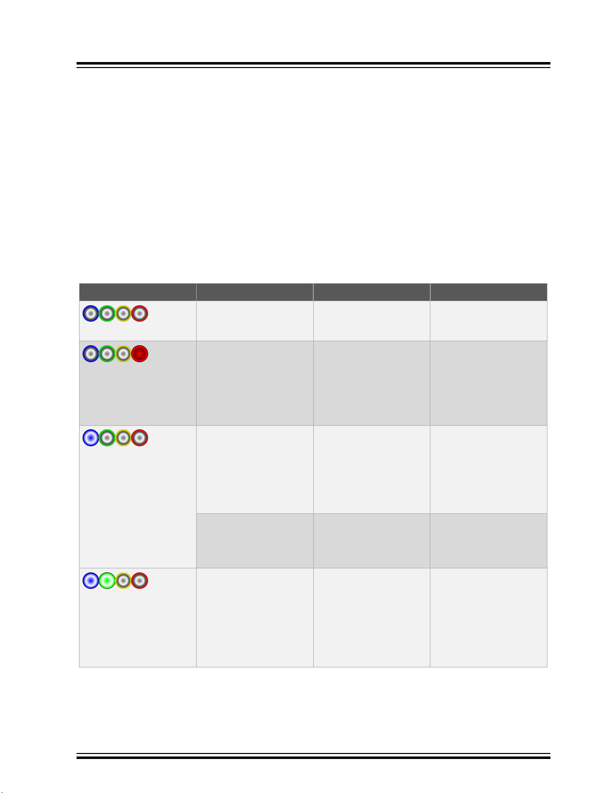
Table 1-1. LED Indicators
LED Color Type Indication Details
Label Pattern
WIFI Solid Blue Wi-Fi Network Connection Indicates a successful connection to
Blue
Blinking Blue
(slow blink)
Soft AP Mode Indicates that the board can be
the local Wi-Fi network.
detected and used as a Wi-Fi
access point. For details, refer to
Section 2.3.3 Via Soft AP.
Overview
Green
Yellow
Red
Blinking Blue
(fast blink)
CONN Solid Green AWS Cloud Connection Indicates a successful MQTT
Blinking
Green
DATA Blinking
Yellow
Solid Yellow
for ON state,
LED Off for
OFF state for
extended time
ERROR Solid Red Error Status Indicates an error in the application.
Wi-Fi Network Connection Indicates that the board is trying to
establish a successful connection to
a Wi-Fi network. In combination with
a blinking green LED, it means that
the board is trying to connect to the
network using default Wi-Fi
credentials.
connection to AWS Cloud.
AWS Cloud Connection Indicates that the board is trying to
establish a MQTT connection to
AWS Cloud
Data Publication to the
Cloud
State of Toggle sent within
MQTT publish packet
Indicates that sensor data in the
form of MQTT packet has been
successfully published to AWS
Cloud.
Indicates the state of the Toggle
switch (ON = 1 / OFF = 0), received
as part of the packet published by
AWS Cloud on the subscribed topic.
1.3 Switch Button Use Cases
The AVR-IoT WA board also has two switches that can be used to enter modes at power-up:
• Hold SW0 for two LED cycles to enter Soft AP mode (refer to Section 2.3.3 Via Soft AP)
• Hold both SW0 and SW1 to use default Wi-Fi credentials. The default credentials are configurable through
MCC, and the application uses the following default values:
Table 1-2. Wi-Fi Credentials
SSID Password
MCHP.IOT microchip
© 2020 Microchip Technology Inc.
User Guide
DS50002998B-page 4
Page 5

2. Getting Started
2.1 Connecting the Board to the Host PC
The AVR-IoT WA development board can be connected to a computer using a standard Micro-USB cable. Once
plugged in, the LED array at the top right-hand corner of the board should flash twice in the following order: Blue,
Green, Yellow, and Red. When the board is not connected to Wi-Fi , the blue LED will blink continuously. The board
will appear as a Removable Storage Device on the host PC, as shown in Curiosity Board as Removable Storage.
Double click the CURIOSITY drive to open it and get started.
Note: All procedures are identical for Windows®, Mac OS®, and Linux® environments.
Figure 2-1. Curiosity Board as Removable Storage
AVR-IoT WA User Guide
Getting Started
The CURIOSITY drive should contain the following five files:
• CLICK-ME.HTM – redirects the user to the AVR-IoT web demo application
• KIT-INFO.HTM – redirects the user to a site containing information and resources about the board
• KIT-INFO.TXT – a text file with details about the PKOB nano firmware and the board’s serial number
• PUBKEY.TXT – a text file with the public key used for data encryption
• STATUS.TXT – a text file with the status of the board
Double click on the CLICK-ME.HTM file to enter the dedicated web page to access the web application.
2.2 The AVR-IoT Webpage
AVR-IoT Webpage shows an image of the AVR-IoT WA webpage. This page displays the sensor data and allows the
user to regenerate the Wi-Fi credentials as a file labeled WIFI.CFG. This can be loaded onto the board, acting as a
storage device to reconfigure access point parameters.
The status markers in the middle of the page, as shown in Webpage Status Indicators, indicate the progress of the
system setup. These markers will light up once each stage has completed successfully.
© 2020 Microchip Technology Inc.
User Guide
DS50002998B-page 5
Page 6

Figure 2-2. AVR-IoT Webpage
AVR-IoT WA User Guide
Getting Started
Figure 2-3. Webpage Status Indicators
The leftmost marker indicates if the board is connected to the host PC. Next to this, the Wi-Fi marker lights up once
the board is connected to a Wi-Fi network and the blue LED will stop blinking and stay on to indicate the board
connection state. To the right of the Wi-Fi marker, the AWS Cloud Message Queuing Telemetry Transport (MQTT)
marker is found, indicating the status of the TCP socket connection and MQTT connection to AWS Cloud. The
corresponding green LED will stop blinking and stay on to indicate the board connection state. Finally, the rightmost
marker lights up, signifying that data is streaming from the board to the cloud. For each successful MQTT publication
of data, yellow LED on the board blinks.
2.3 Connecting the Board to Wi-Fi® Networks
2.3.1 Via AVR-IoT Webpage
There are several ways to connect the AVR-IoT WA Development Board to the Internet. The easiest way is through
the AVR-IoT webpage (www.avr-iot.com/aws). The lower left-hand corner of the site will show a wireless network
connection window where the user can choose to connect to an open (no password required) network or enter the
credentials for a password protected (WPA/WPA2/WEP) Wi-Fi network. Entering Wi-Fi Credentials in AVR-IoT
Webpage shows how to enter the Wi-Fi credentials on the website.
© 2020 Microchip Technology Inc.
User Guide
DS50002998B-page 6
Page 7

Important:
• The Wi-Fi network SSID and password are limited to 31 characters. Avoid using quotation marks,
names, or phrases that begin or end with spaces.
• The AVR-IoT WA Development Board supports only 2.4 GHz networks inline, thus it is recommended
to use mobile hotspots to connect the board to the Internet.
Figure 2-4. Entering Wi-Fi Credentials in AVR-IoT Webpage
AVR-IoT WA User Guide
Getting Started
Once the required details are entered, click the Download Configuration button. This will download the WIFI.CFG
(text) file to the host PC. From the WIFI.CFG’s download location, drag and drop the file to the CURIOSITY drive to
update the Wi-Fi credentials of the board. The blue LED will stop blinking and will stay continuously ON to show a
successful connection to the Wi-Fi Access Point.
Important: Any information entered in the SSID and password fields is not transmitted over the web or to
the Microchip or any of the Cloud servers. Instead, the information is used locally (within the browser) to
generate the WIFI.CFG file.
2.3.2 Via Command Line Interface (CLI)
Another way of connecting to the Wi-Fi is through the Serial Command Line Interface (CLI). This interface can be
accessed through any serial terminal application. Using the UART settings defined in Section 2.5.2 Serial USB
Interface , the user can reconfigure the board to a Wi-Fi network by entering the Wi-Fi command. Wi-Fi Configuration
via Serial Command Line (Open Network) and Wi-Fi Configuration via Serial Command Line (Secured Network)
show examples of trying to connect to open, or secured networks, respectively. For more details on the Wi-Fi
command and its parameters, refer to Section 2.5.2 Serial USB Interface .
© 2020 Microchip Technology Inc.
User Guide
DS50002998B-page 7
Page 8

AVR-IoT WA User Guide
Figure 2-5. Wi-Fi Configuration via Serial Command Line (Open Network)
Figure 2-6. Wi-Fi Configuration via Serial Command Line (Secured Network)
Getting Started
2.3.3 Via Soft AP
The last method to connect to the Wi-Fi is through the advanced Software Access Point (Soft AP) mode, a feature of
the WINC module on-board. This method is ideal if the user is only using a mobile device, such as a mobile phone or
tablet, instead of a laptop or PC. The Soft AP mode can be entered by pressing and holding the SW0 push button for
most of the start-up time between initial power-up LED cycling. When the Soft AP mode has been successfully
entered, the board can be detected as a Wi-Fi access point named MCHP.IOT.ACCESSPOINT. The blue LED will
start blinking when Soft AP is available. Using a mobile device such as a mobile phone or tablet, connect to the
MCHP.IOT.ACCESSPOINT hotspot. It will redirect to a sign-in page where the user can enter the SSID and password
of the network to which the board will connect. The Device Name will not be considered, and the authorization type
will always be WPA/WPA2 (2). Once these details are entered, click the Connect button to connect the board to the
network. Refer to Figure 2-7 to see how the sign-in page will look like.
© 2020 Microchip Technology Inc.
User Guide
DS50002998B-page 8
Page 9

Figure 2-7. Connecting via Soft AP
AVR-IoT WA User Guide
Getting Started
2.4 Visualizing Cloud Data in Real Time
Out of the box, all AVR-IoT WA Development Boards are pre-registered to Microchip’s AWS Cloud sandbox account.
This account is set up for demonstration purposes only. All data gathered by the sensors of the AVR-IoT WA
Development Boards are published on the Microchip sandbox account and can be identified by the following details:
Table 2-1. Project Details
Region: iot.us-east-2
Port: 8883
There is no permanent storage or collection of data published by the boards connected to the Microchip sandbox
account. The full storage catalog of the AWS Cloud features, such as data storage/retention, can be available to the
user with the use of the board once removed from the sandbox and the associated Thing Name/Public Key has been
migrated to a private account.
2.4.1 Publishing data to AWS Cloud
A MQTT publish packet is always sent to the MQTT broker using a specific topic. The AVR-IoT WA Development
Board publishes messages using the topic ‘thingName/sensors’ in communication to the AWS cloud. The
messages published on this topic contains the real-time data obtained from the on-board light and temperature
© 2020 Microchip Technology Inc.
User Guide
DS50002998B-page 9
Page 10

sensors. The frequency of sending a PUBLISH packet can be decided by the user application. The application is
written such that the sensor data is published to the Cloud every second.
2.4.1.1 Updating the Device Shadow
In order to control the device from the Cloud, the AWS Shadow Service feature is used. The AWS Shadow service
maintains a shadow of the device in the form of a JSON document. The device’s state can be stored and retrieved,
leveraging upon the AWS Shadow Topics. To set and get the state of the device, either HTTP or MQTT can be used.
For the demo application, MQTT protocol is chosen. Each device is represented by its unique thing name.
To update the device’s shadow, publish on the topic ‘$aws/things/thingName/shadow/update’.
1. Device updating its reported state:
– The device would publish on this topic to update the state of its reported attributes. Below is an example
of a payload where ‘toggle’ is the attribute:
{
"state" :
{
"reported" :
{
"toggle" : 1
}
}
}
AVR-IoT WA User Guide
Getting Started
– The payload consists of key-value pairs. In the above example, attribute ‘toggle’ is set to ‘1’. The user can
expand the application to add more attributes, which requires updates in the firmware.
2. Client requesting to update a device shadow:
– To request a change in attribute value, the client will publish on the same topic and the payload will be:
{
"state" :
{
"desired" :
{
"toggle" : 1
}
}
}
– The payload consists of key-value pairs. In the above example, attribute ‘toggle’ is set to ‘1’. The user can
expand the application to add more attributes, which requires updates in the firmware.
{
"state" :
{
"reported" :
{
"toggle" : 1
}
}
}
Further information can be found here: /update
Note: Remember to replace thingName with the device's actual thing name.
2.4.2 Subscribing to AWS Shadow Topic
To get information about the device’s shadow from the shadow service, the device has to subscribe to specific
shadow topics. More information on shadow topics can be found here at Shadow MQTT topics.
© 2020 Microchip Technology Inc.
User Guide
DS50002998B-page 10
Page 11

AVR-IoT WA User Guide
Getting Started
The device subscribes to ‘$aws/things/thingName/shadow/update/delta’.The shadow service will send
updates on this topic when there is a difference in attribute values. For example, the reported toggle state is 1 but a
client sent a desired state for toggle as 0. The device would receive update like below:
{
"version": 1349,
"timestamp": 1583450271,
"state": {
"toggle": 0
},
"metadata": {
"toggle": {
"timestamp": 1583450271
}
}
}
Further information can be found here: /update/delta
Note: Remember to replace thingName with the device's actual thing name.
© 2020 Microchip Technology Inc.
User Guide
DS50002998B-page 11
Page 12

AVR-IoT WA User Guide
Figure 2-8. Illustration of AWS Shadow Service Publish-Subscribe Model
Getting Started
2.4.3 Sending the Messages
The AVR-IoT webpage displays a section called What's Next, two sections below the Light and Temperature graphs.
In this section, users can go through the steps of building their own custom application. To quickly preview the
capability to send messages from the Cloud to the board, click the Implement a Cloud-Controlled Actuator ( )
icon, and then click the Learn More button to expand the section.
© 2020 Microchip Technology Inc.
User Guide
DS50002998B-page 12
Page 13

Figure 2-9. What's Next
AVR-IoT WA User Guide
Getting Started
Scroll down to the Control Your Device section. Here, control mechanisms can be seen:
• The Toggle button is used to send the switch value to the AVR-IoT WA board.
The values are only published over the ‘$aws/things/thingName/shadow/update’ topic upon pressing the
Send to device button. Since the board subscribes to ‘$aws/things/thingName/shadow/update/delta’ by
default, the shadow service will send updates on this topic when there is a difference in attribute values. The payload
received here is limited by the MQTT Receive Buffer (bytes) configurable in MQTT library MCC window (see Figure
3-12 for more details).
Figure 2-10. Sending Messages on the Subscribed Topic
2.4.4 Viewing Messages Received on Subscribed Topic
The toggle switch value corresponds to a short forced ON/OFF state to the yellow LED on the AVR-IoT WA
Development Board. The LED will stay on/off for a short time depending on the position of the toggle switch before it
© 2020 Microchip Technology Inc.
User Guide
DS50002998B-page 13
Page 14

resumes normal behavior of blinking to indicate the transmission sensor data through PUBLISH packets. As with
sending messages, the payload is limited by the MQTT Receive Buffer (bytes) configurable in the MQTT library MCC
window.
Figure 2-11. Viewing Messages on a Serial Terminal
There is no permanent storage or collection of the data published by the boards connected through the Microchip
sandbox account. The full storage features available to AWS Cloud are available to the user after the board has been
removed from the Microchip sandbox and migrated to a private account.
2.5 Configuring Other Settings
While the AVR-IoT WA Development Board comes fully programmed and provisioned right out of the box, the user
can still control aspects of the application firmware behavior through the USB interface. There are three methods to
do this:
1. Hex file (reprogram) or WIFI.CFG (reconfigure credentials) drag and drop using the mass storage feature.
2. Commands through the Serial Command Line Interface (CLI), or using MPLAB X IDE.
3. The on-board programmer/debugger PKOB nano.
AVR-IoT WA User Guide
Getting Started
2.5.1 Mass Storage Drag and Drop
There are two ways to utilize the Mass Storage Drag-and-Drop Option:
• Program the embedded device is to drag and drop a .hex file into the CURIOSITY drive. The C compiler
toolchain generates a .hex file for each project it builds. This .hex file contains the code of the project. The
Nano Embedded Debugger (PKoB nano) also provides access to a serial port interface (serial to USB bridge).
This facilitates the user to drag and drop a modified .hex file, which contains the firmware updates. This feature
does not require any USB driver to be installed and works in all major OS environments.
• If the WiFi credentials need to be reconfigured and/or the board needs to connect to the new access point, the
user can enter the new credentials in the AVR-IoT webpage, download the WIFI.cfg file, and then drag and drop
this file into the CURIOSITY drive. The board securely remembers the last successful connection to the access
point.
2.5.2 Serial USB Interface
The Wi-Fi Access Point credentials can be reconfigured through a Serial Command Line Interface (CLI) on the AVRIoT WA Development Boards. This interface may also be used to provide application diagnostic information. To
access this interface, use any preferred serial terminal application (Tera Term, CoolTerm, and PuTTy) and open the
serial port labeled Curiosity Virtual COM port, with the following settings:
Table 2-2. Serial USB Interface Settings
Baud rate Data Parity bit Stop bit Flow control Local echo Transmit protocol
9600 8 bits None 1 bit None ON CR+LF (Carriage Return +
Note: For Windows® users, the USB serial interface requires the installation of a USB serial port driver, included in
the installation of the MPLAB® X IDE.
The user can control the board by typing the command keywords, listed in Serial Command Line Commands:
Line Feed)
© 2020 Microchip Technology Inc.
User Guide
DS50002998B-page 14
Page 15
AVR-IoT WA User Guide
Getting Started
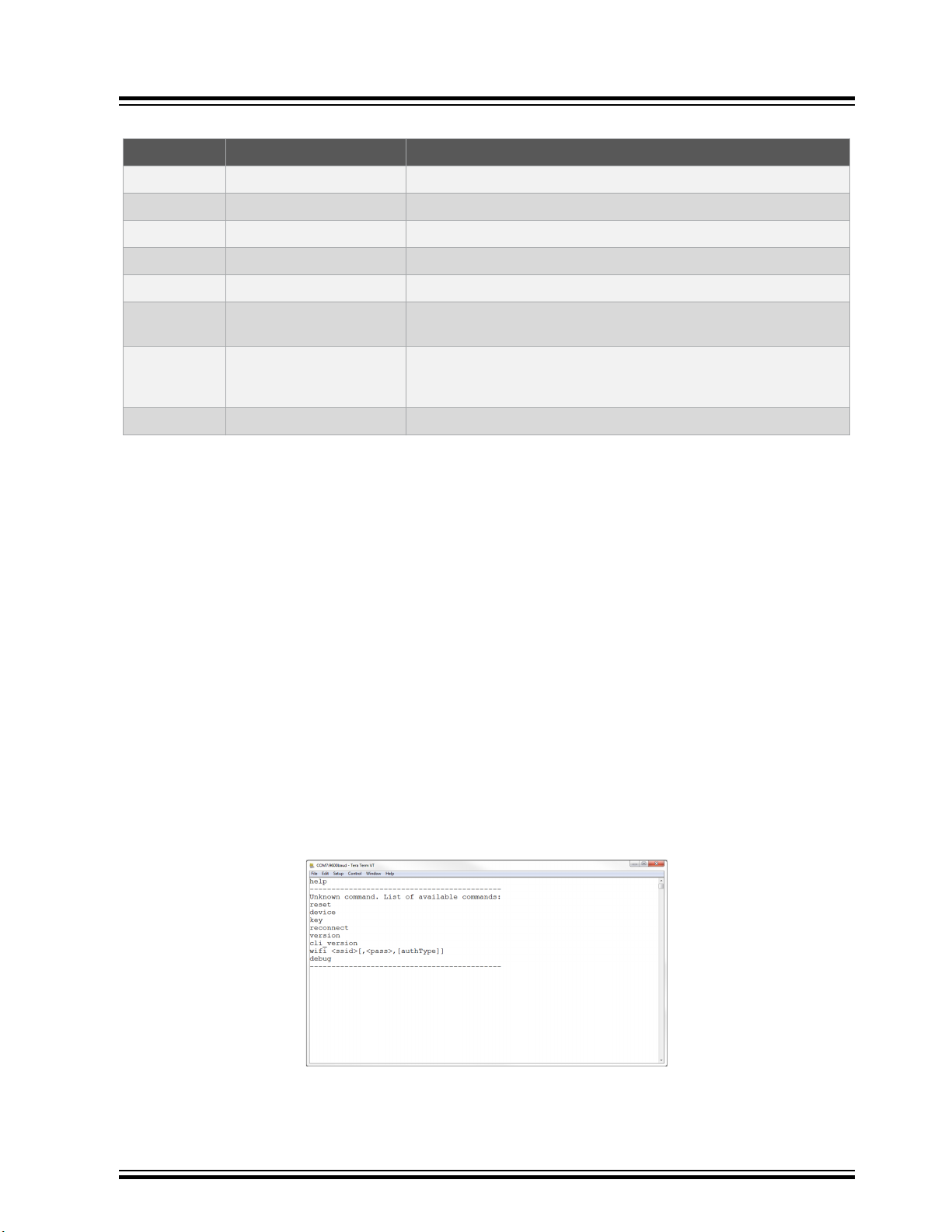
Table 2-3. Serial Command Line Commands
Command Arguments Description
reset
device
thing
reconnect
version
cli_version
wifi
debug
*- Authorization Type options are available by typing one of the following three numbers to determine the network
security option used:
1. Open – Password and Security option parameters are not required.
2. WPA/WPA2 – Security Option Parameter not required.
3. WEP – Network Name, Password, and Security Option (3) Parameter are required when connecting to a WEP
network. For example, ‘wifi MCHP.IOT,microchip,3’.
— Reset the settings on the device
— Print the unique device ID of the on-board ECC device
— Print the unique thing name of the board
— Re-establish connection to the Cloud
— Print the version of the AVR-IoT firmware library
— Print the command line interface firmware version of the AVR-IoT
library
<Network SSID>,
<Password>, <Security
Option*>
<Debug Options**> Print debug messages to see status of board operation
Enter the Wi-Fi network authentication details
**- The debug option won't work unless the user selects Enable debug messages option in the AVR-IoT Sensor
Node Library. Configured Debug Severity level is used to determine messages displayed using debug_printer():
0. Normal – At this level, only standard operating behavior or data are displayed.
1. Warning – At this level, information related to nuance in operation or configuration is displayed.
2. Notice – At this level, alerts or context-specific information is displayed.
3. Info – At this level, operation or variable information relevant to the end application is displayed.
4. Debug – At this level, error messages, state, or run-time variations during problem solving or development process
are displayed.
Note: Setting the Debug Severity level also enables the printing of all other information or messages associated
with all levels beneath the set Debug Severity level (e.g., Severity level of NOTICE will also result in WARNING and
NORMAL level debug messages to also be displayed). Extensive use of Debug logger at ANY severity level requires
memory and execution resources which could affect application behavior.
Figure 2-12. Serial Command Line Interface
© 2020 Microchip Technology Inc.
User Guide
DS50002998B-page 15
Page 16

2.5.3 Onboard Programmer/Debugger Interface
For users familiar with the MPLAB X IDE, the AVR-IoT boards can be programmed, and/or debugged directly through
the IDE. The AVR-IoT Development Boards are automatically detected by the MPLAB X, enabling full programming
and debugging through the on-board PKOB nano interface. For code generation, see Section 3. Code Source
Platforms on how to generate a sample application code in MCC.
2.6 Migrating to a Private AWS Cloud Account
Once the features and capabilities of the AVR-IoT WA board have been explored, the user can begin the process to
move development out of the MCHP sandbox environment and into a private AWS Cloud. In MCC, under the settings
for the AVR-IoT AWS Sensor Node Library, tick the Use custom endpoint URL check box and fill in the AWS cloud
details. Hit the Generate button, and make and program the board.
Figure 2-13. Migrating to a Private AWS Cloud Account
AVR-IoT WA User Guide
Getting Started
© 2020 Microchip Technology Inc.
User Guide
DS50002998B-page 16
Page 17

3. Code Source Platforms
3.1 Code Generation from MCC
The source code of the AVR-IoT WA development board demo program is available for generation via the MPLAB
Code Configurator (MCC) plugin in MPLAB X IDE. To generate the code, the following software and the appropriate
versions should be installed.
Table 3-1. Software Versions
Software Version
MPLAB® X IDE 5.40 or later
AVR-IoT WA User Guide
Code Source Platforms
®
Compilers
• AVR GCC
• XC8
MPLAB® Code Configurator (MCC) 4.0.0 or later
AVR-IoT AWS Sensor Node Library 1.0.1
3.1.1 Generating the Demo
Once the board is connected to the host machine and MPLAB X is launched, see the description in the sections from
3.1.1.1 Creating the MPLAB X Project to 3.1.1.4 Generating MCC Files and Programming the Board for how to
generate a microcontroller code for it.
3.1.1.1 Creating the MPLAB X Project
1. Create a new stand-alone project (see Create New Project) in MPLAB X using the ATmega4808 as the device
(see Selecting a Device); the PKOB nano as a programming tool (see Selecting a Programmer); and the XC8
or AVR GCC as a compiler (see Selecting a Compiler). Finally, name the MPLAB project and its location (see
Naming a New Project). The Start page of MPLAB X will then appear.
2. On the MPLAB X toolbar, look for and click the MPLAB®\ Code Configurator (MCC) Icon (
> Embedded > MPLAB X Code Configurator v3 Open/Close. For assistance with installation, refer to MPLAB
Code Configurator Page (www.microchip.com/mplab/mplab-code-configurator)
3. Under Device Resources, scroll down to the Internet of Things header. Under Examples, double click on
AVR-IoT AWS Sensor Node (see MCC Start Page).
Versions:
• 5.4.0 or later
• 2.20 or later
) or click Tools
®
© 2020 Microchip Technology Inc.
User Guide
DS50002998B-page 17
Page 18
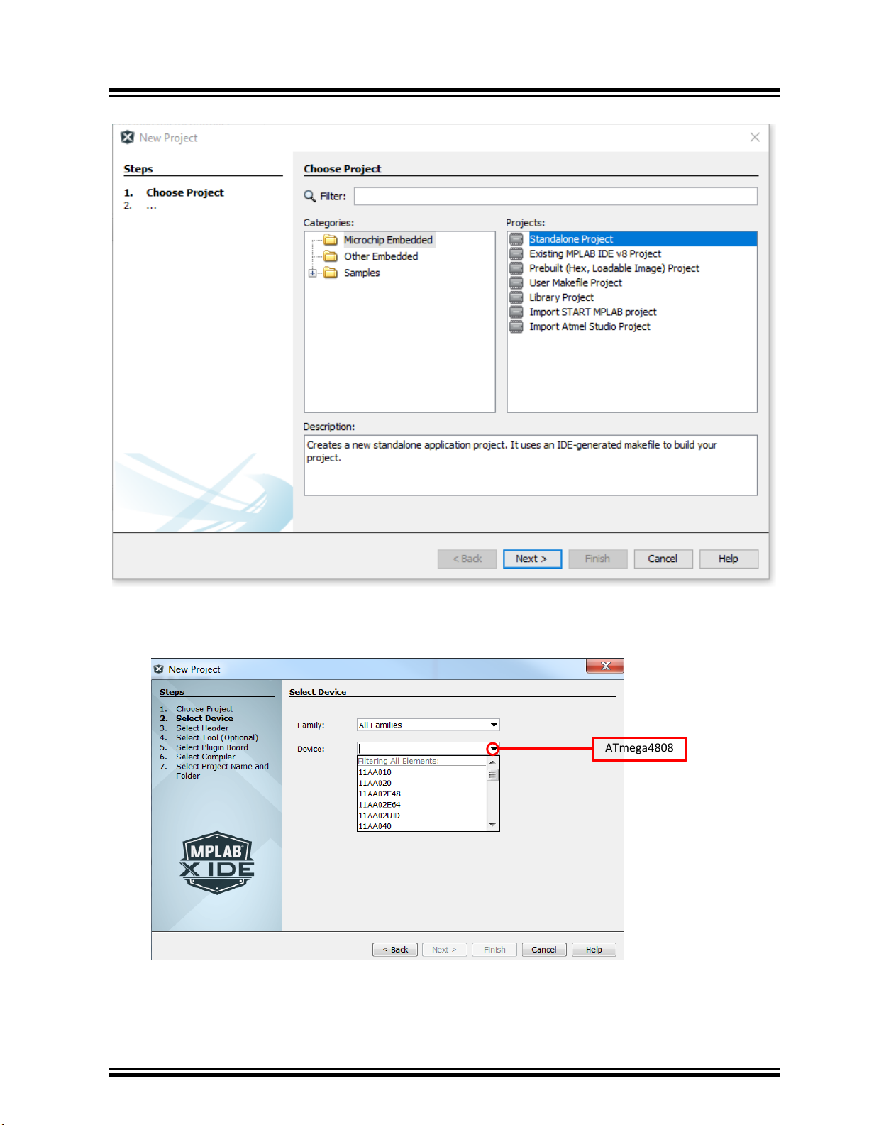
Figure 3-1. Create New Project
ATmega480
8
AVR-IoT WA User Guide
Code Source Platforms
Figure 3-2. Selecting a Device
© 2020 Microchip Technology Inc.
User Guide
DS50002998B-page 18
Page 19
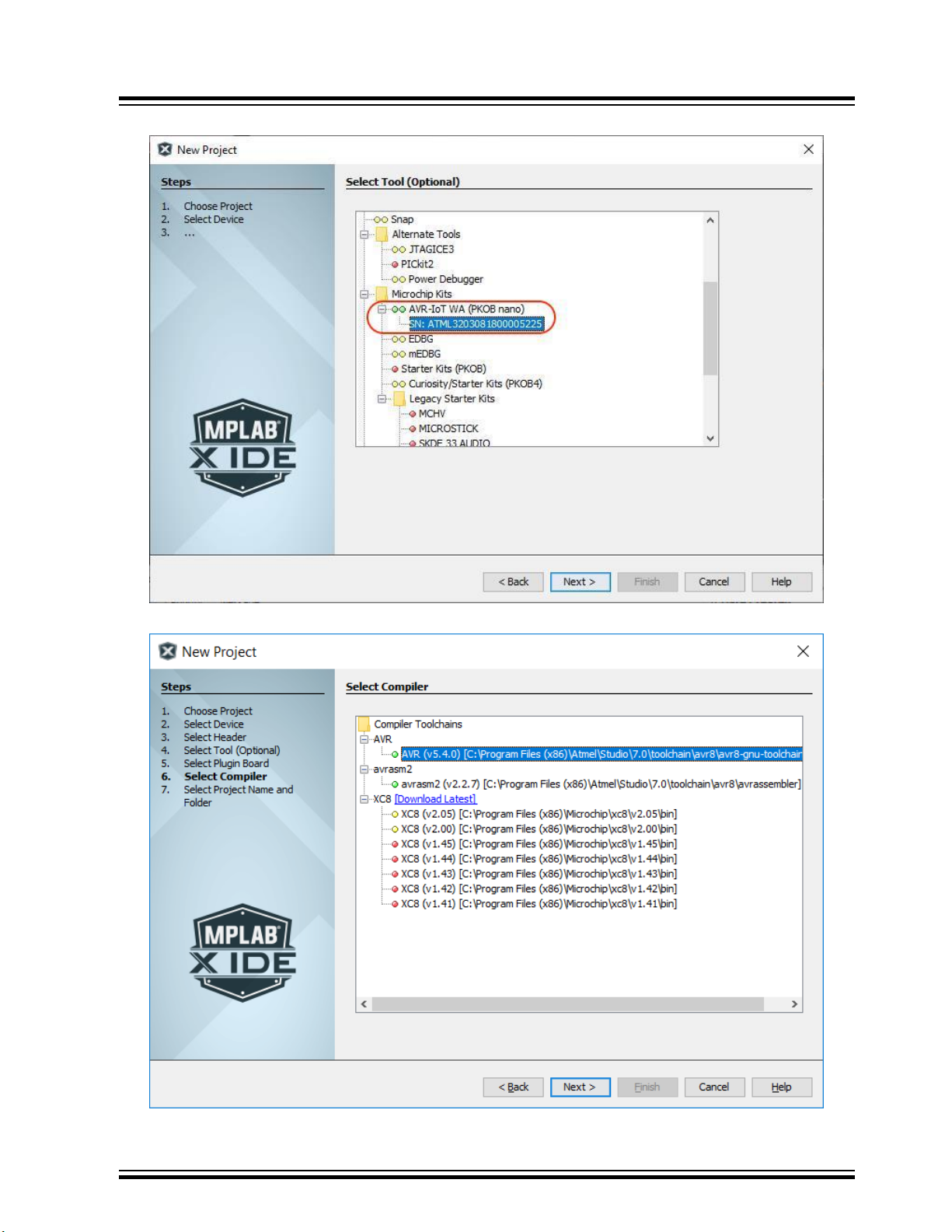
Figure 3-3. Selecting a Programmer
AVR-IoT WA User Guide
Code Source Platforms
Figure 3-4. Selecting a Compiler
© 2020 Microchip Technology Inc.
User Guide
DS50002998B-page 19
Page 20

Figure 3-5. Naming a New Project
AVR-IoT WA User Guide
Code Source Platforms
Figure 3-6. MCC Start Page
3.1.1.2 Configuring the Settings of the Project
The example module makes use of multiple libraries and peripherals. To configure the libraries, double click on each
library in the Device Resources window to view their setup windows.
© 2020 Microchip Technology Inc.
User Guide
DS50002998B-page 20
Page 21

Figure 3-7. AVR-IoT Peripheral Libraries
Figure 3-8. AVR-IoT AWS Sensor Node Library Configuration
AVR-IoT WA User Guide
Code Source Platforms
3.1.1.3 Component Libraries and Peripherals
Important: Launching MCC v3.95 or earlier will automatically install an obsolete deprecated version of
the AVR-IoT WG library. To avoid using this outdated library and its components, always check that you
are loading the AVR-IoT AWS Sensor Node Library and not the "AVR-IoT WG Sensor Node" Library. The
correct library will also have a blue question mark beside its name as shown below. The correct
component libraries used by the module will be under Libraries in Device Resources panel.
© 2020 Microchip Technology Inc.
User Guide
DS50002998B-page 21
Page 22

AVR-IoT WA User Guide
Code Source Platforms
• CrypthoAuthLib – The Crypto Authentication Library (CryptoAuthLib) shows the settings needed to configure the
on-board ECC608 chip that provides the security features of the AVR-IoT WA board to work. It also indicates the
communication settings between the ECC608 chip and the embedded microcontroller on-board, as shown in
CryptoAuthLib MCC.
• WINC – Under the WINC library, the user can configure the default SSID, password, authentication type, and
inclusion of IPSocket for the network to which the board will be connected, as seen in WINC MCC.
• Message Queuing Telemetry Transport (MQTT) – MQTT is used as a messaging protocol which operates on top
of a TCP/UDP connection to transporting data between client and broker over the Cloud. In MCC, the user can
change their MQTT host and connection time-out duration, as shown in MQTT MCC for desired application
configuration).
Figure 3-9. CryptoAuthLib MCC
© 2020 Microchip Technology Inc.
User Guide
DS50002998B-page 22
Page 23

Figure 3-10. WINC MCC
AVR-IoT WA User Guide
Code Source Platforms
© 2020 Microchip Technology Inc.
User Guide
DS50002998B-page 23
Page 24

Figure 3-11. MQTT MCC
AVR-IoT WA User Guide
Code Source Platforms
3.1.1.4 Generating MCC Files and Programming the Board
• After the addition and/or configuration of component libraries and peripherals, click the Generate button on the
left-hand corner of the window, as shown in the Generating MCC Code, and wait for the generation to complete.
• Click the Make and Program Device button near the middle of the toolbar. Make sure the board is connected to
the system during programming.
© 2020 Microchip Technology Inc.
User Guide
DS50002998B-page 24
Page 25

Figure 3-12. Generating MCC Code
Figure 3-13. Make and Program Device in MPLAB X
AVR-IoT WA User Guide
Code Source Platforms
3.2 Getting the Source Code from GitHub
The source code for the AVR-IoT WA development board can also be downloaded from GitHub. There are different
versions of the source code for MPLAB X and Atmel Studio. The hex file is also available for download from the
releases tab for drag-and-drop programming. Refer to the table below for the links to the GitHub deployments. For full
URLs to the links below, refer to the Relevant Links section of this document.
Table 3-2. GitHub Deployment Links
MPLAB X Atmel Studio
Source Code Source Code
.hex file .hex file
© 2020 Microchip Technology Inc.
User Guide
DS50002998B-page 25
Page 26

4. Hardware Guide
The AVR-IoT WG and AVR-IoT WA boards, collectively referred to as the AVR-IoT Wx boards, share the same
hardware components, configuration, and schematics. For in-depth information on the hardware features of the AVRIoT Wx boards, see the full AVR-IoT Wx Hardware User Guide. For the full URL of the document, refer to the
Relevant Links section of this document.
AVR-IoT WA User Guide
Hardware Guide
© 2020 Microchip Technology Inc.
User Guide
DS50002998B-page 26
Page 27

5. FAQs, Tips, and Troubleshooting
5.1 FAQs and Tips
1. How can the user change the Wi-Fi configuration?
There are four ways to do it:
1. Connect to the USB and click the ‘click-me’ file to reach the dedicated page for the device and enter the
new credentials in the web form. Download the resulting file to the CURIOSITY drive. Read more in Section
2.3.1 Via AVR-IoT Webpage.
2. Connect to the USB and open a serial port terminal (Windows users will need to install serial port drivers).
From the command line, use the Wi-fi command. Read more in Section 2.3.1 Via AVR-IoT Webpage.
3. Press the SW0 button while powering up the board and the WINC will turn to Access Point mode. Connect the
laptop or phone to it and fill in the online form. See Section 2.3 Connecting the Board to Wi-Fi Networks for
details.
4. Use MCC to re-build the project after changing the default Wi-Fi configuration in the WINC module.
Reprogram the board using MPLAB X or drag and drop the new image to the CURIOSITY drive. Further
details can be found in Section 3.1 Code Generation from MCC .
2. How can the user change the Wi-Fi credentials using the online form without exposing the details to
security threats?
Although it appears in the browser, the Wi-Fi credential setup form does not transfer any information to third parties.
A small text file (WIFI.CFG) is created (this can also be done manually using any text editor) and it is recommended
that saves it directly to the CURIOSITY drive. Since the browser settings vary according to the platform and personal
preferences, the user might have to change them or perform a drag and drop from the default download folder. Even
though it looks like the WIFI.CFG file is now stored on the CURIOSITY drive, this is just an artifact of the operating
system (caching). No file is permanently recorded and the information contained is immediately used to update the
Wi-Fi module settings. These settings will be maintained after subsequent power cycles of the AVR-IoT Development
Board, but the file will disappear.
3. Can a phone/tablet alone be used to perform the demo?
Assuming the user has a way to provide power to the board (a USB back up battery, a USB charger, a Li-Ion battery,
or other 3.3V-5V power supply), the QR code can be scanned (on a sticker under the board, next to the Microchip
and Amazon color logos) using any smartphone camera (old operating system versions might still require a separate
app) and open the resulting link in the smartphone browser.
4. The user scanned the bar code with the phone/tablet, but nothing happened?
Ensure the scanning of the QR code present on the sticker under the AVR-IoT WA board. It can be recognized by the
distinguishing squares on the three of its corners and its proximity (same sticker) to the MCHP and Amazon logos (in
color). Although there are also other bar codes present on the Wi-Fi module, and/or the anti-static bag the board
came with, those are not QR codes.
5. Which battery is recommended to be used with the AVR-IoT WA Sensor Node board?
Microchip recommends Li-Ion or Li-Poly batteries with at least 400 mAh capacity and 3.7V nominal. For more
information about powering the board, refer to the AVR-IoT Wx Hardware User Guide.
Other Helpful Tips:
The following steps are not required for operating the AVR-IoT WA Sensor Node board, but will significantly increase
the possibility of positive results.
1. Get a USB cable with all the four wires connected. There are a lot of non-compliant USB cables available
that provide only 5V power (two wires). How can the user verify it? Plug the board into the laptop and check in
the File Manager (Finder) for the presence of a new hard drive (named CURIOSITY). If it fails to pop up after a
second or two, the cable is not the appropriate one.
2. Prepare the Wi-Fi router for the demo. The easiest way to go is to set up the phone as a hotspot. The
following credentials should be used, name (SSID): MCHP.IOT and password: microchip (WPA 2 is assumed,
AVR-IoT WA User Guide
FAQs, Tips, and Troubleshooting
© 2020 Microchip Technology Inc.
User Guide
DS50002998B-page 27
Page 28
do no use WEP nor OPEN.) This Wi-Fi configuration is the factory default for all boards, so it will minimize the
effort for first-time users. If preparing for a (medium/large) classroom demo, the user should set up a proper
Wi-Fi router (2.4 GHz) instead. This will give a better range and capacity while using the same Wi-Fi
credentials, if possible.
3. Make Google Chrome or Firefox the default web browser. Safari works well on MACs. Internet Explorer is not
recommended.
4. Ensure no pop-up blockers or other anti-virus browser extensions are active. These can and will interfere with
the script that is at the heart of the microsite. Often, these can be selectively disabled for that specific
webpage.
5. Take into account the amount of Wi-Fi pollution in the place where the board is operated.
6. If using a router, verify that the network does not have a firewall that can block access to the AWS Cloud
server. If using a mobile 4G (or phone LTE hotspot) for Internet connectivity, ensure it is fully charged and does
not have any firewall settings that might block access.
5.2 LED Status Troubleshooting
Table 5-1. Application LED Troubleshooting
LED Sequence Description Diagnosis Action
All LEDs are OFF Board is not programmed Download the image .hex
AVR-IoT WA User Guide
FAQs, Tips, and Troubleshooting
file from GitHub or the
AVR-IoT website
Only Red LED is ON Indicates a hardware fault
issue with the development
board
Blue LED BLINKS slowly
(at 0.5s rate) with all other
LEDs OFF
Blue LED BLINKS quickly
(at 0.25s rate) with all other
LEDs OFF
Green LED is BLINKING;
Blue LED is also
BLINKING quickly (at 0.25s
rate)
Board is in Soft AP mode • Connect to the board
Board is not connected to
an access point and trying
to connect.
Board is using WiFi
DEFAULT CREDENTIALS
With debug option enabled
in MCC, connect to serial
terminal and pass the
command ‘debug 4’. This
will print out the log
indicating the cause of the
error.
using a phone or a
network capable
device
• Send updated
credentials via Soft
AP
• Verify the access point
credentials
• Verify if the access
point is online
• Allow board to
connect to Access
Point
• Update
CREDENTIALS
through CLI if
DEFAULTS selection
was invalid
© 2020 Microchip Technology Inc.
User Guide
DS50002998B-page 28
Page 29

AVR-IoT WA User Guide
FAQs, Tips, and Troubleshooting
...........continued
LED Sequence Description Diagnosis Action
OR
Blue LED is ON, Green
LED is BLINKING
Blue and Green LEDs are
ON but Yellow LED is OFF
Blue and Green LEDs are
ON. Yellow LED is
BLINKING.
Blue and Green LEDs are
ON. Yellow LED held high/
low.
Board is not connected to
the AWS Cloud Servers
Sensor data is not being
published to Cloud
Everything is working • No action required
Subscribe topic toggle
value received
• Verify MQTT required
ports
• Verify project
credentials
• Check local network
firewall settings
• Use tethered cell
phone or laptop
connection for internet
• Verify device
registration to the
project
• Check AWS account
settings
• Nothing to do
• LED will reflect
‘Toggle’ value LED
behavior returns to
normal after HOLD
PERIOD
Table 5-2. PKOB nano LED Troubleshooting
LED Sequence Description Diagnosis Action
PKOB nano LED is OFF Board is not powered • Check the USB
• Replace the board
PKOB nano LED is ON but
CURIOSITY driver is not
found
PKoB nano LED is blinking Debugger is working No action required. Refer
Faulty USB connection • Check the PC device
• Replace the USB
to the AVR-IoT Wx
Hardware User Guide for
more details.
connection
manager
cable
© 2020 Microchip Technology Inc.
User Guide
DS50002998B-page 29
Page 30

6. Relevant Links
The following tables contain links to the most relevant documents and software for the AVR-IoT Wx Development
Boards. For those accessing the electronic version of this document, the active links below will redirect to the
appropriate website.
Table 6-1. AVR-IoT Relevant Links and Documentation
AVR-IoT WA User Guide
Relevant Links
URL Description
AVR-IoT WG website www.microchip.com/DevelopmentTools/
ProductDetails.aspx?PartNO=AC164160
AVR-IoT WG on
MCHPDirect
AVR-IoT WA website www.microchip.com/DevelopmentTools/
AVR-IoT WA on
MCHPDirect
AVR-IoT Wx Hardware
User Guide
AVR-IoT WG for
MPLAB X on GitHub
AVR-IoT WG for Atmel
Studio on GitHub
www.microchipdirect.com/ProductSearch.aspx?
Keywords=AC164160
ProductDetails.aspx?PartNO=EV15R70A
www.microchipdirect.com/ProductSearch.aspx?
Keywords=EV15R70A
microchip.com/DS50002805 Find more information on the
Source code
• github.com/microchip-pic-avr-solutions/avr-iot-
google-sensor-node-mplab
.hex file
• github.com/microchip-pic-avr-solutions/avr-iot-
google-sensor-node-mplab/releases/latest
Source code
• github.com/microchip-pic-avr-solutions/avr-iot-
google-sensor-node-studio
.hex file
• github.com/microchip-pic-avr-solutions/avr-iot-
google-sensor-node-studio/releases/latest
Find schematics, design files, and
purchase the board. Set up for
Google Cloud IoT Core
Purchase the AVR-IoT WG board
on Microchip Direct
Find schematics, design files, and
purchase the board. Set up for
Amazon Web Services
Purchase the AVR-IoT WA board
on Microchip Direct
hardware of the AVR-IoT Wx
boards.
Download the AVR-IoT WG source
code and .hex files for MPLAB X
from GitHub
Download the AVR-IoT WG source
code and .hex files for Atmel Studio
from GitHub
AVR-IoT WA for MPLAB
X on GitHub
AVR-IoT WA for Atmel
Studio on GitHub
© 2020 Microchip Technology Inc.
Source code
.hex file
Source code
.hex file
• github.com/microchip-pic-avr-solutions/avr-iot-
aws-sensor-node-mplab
• github.com/microchip-pic-avr-solutions/avr-iot-
aws-sensor-node-mplab/releases/latest
• github.com/microchip-pic-avr-solutions/avr-iot-
aws-sensor-node-studio
• github.com/microchip-pic-avr-solutions/avr-iot-
aws-sensor-node-studio/releases/latest
User Guide
Download the AVR-IoT WA source
code and .hex files for MPLAB X
from GitHub
Download the AVR-IoT WA source
code and .hex files for Atmel Studio
from Gitb
DS50002998B-page 30
Page 31

Table 6-2. Related Tools and Resources
URL Description
AVR-IoT WA User Guide
Relevant Links
MPLAB X IDE www.microchip.com/mplab/
mplab-x-ide
Atmel Studio www.microchip.com/
development-tools/atmelstudio-7
MPLAB Code
Configurator
(MCC)
Atmel START www.microchip.com/start Online tool that helps the user to select and configure
Microchip Sample
Store
Data Visualizer www.microchip.com/mplab/
www.microchip.com/mplab/
mplab-code-configurator
www.microchip.com/samples/
default.aspx
avr-support/data-visualizer
Free IDE to develop applications for Microchip
microcontrollers and digital signal controllers.
Free IDE for the development of C/C++ and assembler code
for microcontrollers.
Free, graphical programming environment that generates
seamless, easy-to-understand C code to be inserted into the
project. Using an intuitive interface, it enables and configures
a rich set of peripherals and functions specific to the
application.
software components and tailor the embedded application in a
usable and optimized manner.
Microchip sample store where the user can order samples of
devices.
A program used for processing and visualizing data. The Data
Visualizer can receive data from various sources such as the
Embedded Debugger Data Gateway Interface found on
Xplained Pro boards and COM ports.
© 2020 Microchip Technology Inc.
User Guide
DS50002998B-page 31
Page 32

7. Revision History
Revision Date Comments
B 09/2020 Updated required library versions to be compatible with MCC v4.0.0.
A 06/2020 Initial document release.
AVR-IoT WA User Guide
Revision History
© 2020 Microchip Technology Inc.
User Guide
DS50002998B-page 32
Page 33

AVR-IoT WA User Guide
The Microchip Website
Microchip provides online support via our website at www.microchip.com/. This website is used to make files and
information easily available to customers. Some of the content available includes:
• Product Support – Data sheets and errata, application notes and sample programs, design resources, user’s
guides and hardware support documents, latest software releases and archived software
• General Technical Support – Frequently Asked Questions (FAQs), technical support requests, online
discussion groups, Microchip design partner program member listing
• Business of Microchip – Product selector and ordering guides, latest Microchip press releases, listing of
seminars and events, listings of Microchip sales offices, distributors and factory representatives
Product Change Notification Service
Microchip’s product change notification service helps keep customers current on Microchip products. Subscribers will
receive email notification whenever there are changes, updates, revisions or errata related to a specified product
family or development tool of interest.
To register, go to www.microchip.com/pcn and follow the registration instructions.
Customer Support
Users of Microchip products can receive assistance through several channels:
• Distributor or Representative
• Local Sales Office
• Embedded Solutions Engineer (ESE)
• Technical Support
Customers should contact their distributor, representative or ESE for support. Local sales offices are also available to
help customers. A listing of sales offices and locations is included in this document.
Technical support is available through the website at: www.microchip.com/support
Microchip Devices Code Protection Feature
Note the following details of the code protection feature on Microchip devices:
• Microchip products meet the specifications contained in their particular Microchip Data Sheet.
• Microchip believes that its family of products is secure when used in the intended manner and under normal
conditions.
• There are dishonest and possibly illegal methods being used in attempts to breach the code protection features
of the Microchip devices. We believe that these methods require using the Microchip products in a manner
outside the operating specifications contained in Microchip’s Data Sheets. Attempts to breach these code
protection features, most likely, cannot be accomplished without violating Microchip’s intellectual property rights.
• Microchip is willing to work with any customer who is concerned about the integrity of its code.
• Neither Microchip nor any other semiconductor manufacturer can guarantee the security of its code. Code
protection does not mean that we are guaranteeing the product is “unbreakable.” Code protection is constantly
evolving. We at Microchip are committed to continuously improving the code protection features of our products.
Attempts to break Microchip’s code protection feature may be a violation of the Digital Millennium Copyright Act.
If such acts allow unauthorized access to your software or other copyrighted work, you may have a right to sue
for relief under that Act.
© 2020 Microchip Technology Inc.
User Guide
DS50002998B-page 33
Page 34

AVR-IoT WA User Guide
Legal Notice
Information contained in this publication is provided for the sole purpose of designing with and using Microchip
products. Information regarding device applications and the like is provided only for your convenience and may be
superseded by updates. It is your responsibility to ensure that your application meets with your specifications.
THIS INFORMATION IS PROVIDED BY MICROCHIP “AS IS”. MICROCHIP MAKES NO REPRESENTATIONS OR
WARRANTIES OF ANY KIND WHETHER EXPRESS OR IMPLIED, WRITTEN OR ORAL, STATUTORY OR
OTHERWISE, RELATED TO THE INFORMATION INCLUDING BUT NOT LIMITED TO ANY IMPLIED
WARRANTIES OF NON-INFRINGEMENT, MERCHANTABILITY, AND FITNESS FOR A PARTICULAR PURPOSE
OR WARRANTIES RELATED TO ITS CONDITION, QUALITY, OR PERFORMANCE.
IN NO EVENT WILL MICROCHIP BE LIABLE FOR ANY INDIRECT, SPECIAL, PUNITIVE, INCIDENTAL OR
CONSEQUENTIAL LOSS, DAMAGE, COST OR EXPENSE OF ANY KIND WHATSOEVER RELATED TO THE
INFORMATION OR ITS USE, HOWEVER CAUSED, EVEN IF MICROCHIP HAS BEEN ADVISED OF THE
POSSIBILITY OR THE DAMAGES ARE FORESEEABLE. TO THE FULLEST EXTENT ALLOWED BY LAW,
MICROCHIP'S TOTAL LIABILITY ON ALL CLAIMS IN ANY WAY RELATED TO THE INFORMATION OR ITS USE
WILL NOT EXCEED THE AMOUNT OF FEES, IF ANY, THAT YOU HAVE PAID DIRECTLY TO MICROCHIP FOR
THE INFORMATION. Use of Microchip devices in life support and/or safety applications is entirely at the buyer’s risk,
and the buyer agrees to defend, indemnify and hold harmless Microchip from any and all damages, claims, suits, or
expenses resulting from such use. No licenses are conveyed, implicitly or otherwise, under any Microchip intellectual
property rights unless otherwise stated.
Trademarks
The Microchip name and logo, the Microchip logo, Adaptec, AnyRate, AVR, AVR logo, AVR Freaks, BesTime,
BitCloud, chipKIT, chipKIT logo, CryptoMemory, CryptoRF, dsPIC, FlashFlex, flexPWR, HELDO, IGLOO, JukeBlox,
KeeLoq, Kleer, LANCheck, LinkMD, maXStylus, maXTouch, MediaLB, megaAVR, Microsemi, Microsemi logo, MOST,
MOST logo, MPLAB, OptoLyzer, PackeTime, PIC, picoPower, PICSTART, PIC32 logo, PolarFire, Prochip Designer,
QTouch, SAM-BA, SenGenuity, SpyNIC, SST, SST Logo, SuperFlash, Symmetricom, SyncServer, Tachyon,
TempTrackr, TimeSource, tinyAVR, UNI/O, Vectron, and XMEGA are registered trademarks of Microchip Technology
Incorporated in the U.S.A. and other countries.
APT, ClockWorks, The Embedded Control Solutions Company, EtherSynch, FlashTec, Hyper Speed Control,
HyperLight Load, IntelliMOS, Libero, motorBench, mTouch, Powermite 3, Precision Edge, ProASIC, ProASIC Plus,
ProASIC Plus logo, Quiet-Wire, SmartFusion, SyncWorld, Temux, TimeCesium, TimeHub, TimePictra, TimeProvider,
Vite, WinPath, and ZL are registered trademarks of Microchip Technology Incorporated in the U.S.A.
Adjacent Key Suppression, AKS, Analog-for-the-Digital Age, Any Capacitor, AnyIn, AnyOut, BlueSky, BodyCom,
CodeGuard, CryptoAuthentication, CryptoAutomotive, CryptoCompanion, CryptoController, dsPICDEM,
dsPICDEM.net, Dynamic Average Matching, DAM, ECAN, EtherGREEN, In-Circuit Serial Programming, ICSP,
INICnet, Inter-Chip Connectivity, JitterBlocker, KleerNet, KleerNet logo, memBrain, Mindi, MiWi, MPASM, MPF,
MPLAB Certified logo, MPLIB, MPLINK, MultiTRAK, NetDetach, Omniscient Code Generation, PICDEM,
PICDEM.net, PICkit, PICtail, PowerSmart, PureSilicon, QMatrix, REAL ICE, Ripple Blocker, SAM-ICE, Serial Quad
I/O, SMART-I.S., SQI, SuperSwitcher, SuperSwitcher II, Total Endurance, TSHARC, USBCheck, VariSense,
ViewSpan, WiperLock, Wireless DNA, and ZENA are trademarks of Microchip Technology Incorporated in the U.S.A.
and other countries.
SQTP is a service mark of Microchip Technology Incorporated in the U.S.A.
The Adaptec logo, Frequency on Demand, Silicon Storage Technology, and Symmcom are registered trademarks of
Microchip Technology Inc. in other countries.
GestIC is a registered trademark of Microchip Technology Germany II GmbH & Co. KG, a subsidiary of Microchip
Technology Inc., in other countries.
All other trademarks mentioned herein are property of their respective companies.
©
2020, Microchip Technology Incorporated, Printed in the U.S.A., All Rights Reserved.
ISBN: 978-1-5224-6779-3
© 2020 Microchip Technology Inc.
User Guide
DS50002998B-page 34
Page 35

AVR-IoT WA User Guide
Quality Management System
For information regarding Microchip’s Quality Management Systems, please visit www.microchip.com/quality.
© 2020 Microchip Technology Inc.
User Guide
DS50002998B-page 35
Page 36

Worldwide Sales and Service
AMERICAS ASIA/PACIFIC ASIA/PACIFIC EUROPE
Corporate Office
2355 West Chandler Blvd.
Chandler, AZ 85224-6199
Tel: 480-792-7200
Fax: 480-792-7277
Technical Support:
www.microchip.com/support
Web Address:
www.microchip.com
Atlanta
Duluth, GA
Tel: 678-957-9614
Fax: 678-957-1455
Austin, TX
Tel: 512-257-3370
Boston
Westborough, MA
Tel: 774-760-0087
Fax: 774-760-0088
Chicago
Itasca, IL
Tel: 630-285-0071
Fax: 630-285-0075
Dallas
Addison, TX
Tel: 972-818-7423
Fax: 972-818-2924
Detroit
Novi, MI
Tel: 248-848-4000
Houston, TX
Tel: 281-894-5983
Indianapolis
Noblesville, IN
Tel: 317-773-8323
Fax: 317-773-5453
Tel: 317-536-2380
Los Angeles
Mission Viejo, CA
Tel: 949-462-9523
Fax: 949-462-9608
Tel: 951-273-7800
Raleigh, NC
Tel: 919-844-7510
New York, NY
Tel: 631-435-6000
San Jose, CA
Tel: 408-735-9110
Tel: 408-436-4270
Canada - Toronto
Tel: 905-695-1980
Fax: 905-695-2078
Australia - Sydney
Tel: 61-2-9868-6733
China - Beijing
Tel: 86-10-8569-7000
China - Chengdu
Tel: 86-28-8665-5511
China - Chongqing
Tel: 86-23-8980-9588
China - Dongguan
Tel: 86-769-8702-9880
China - Guangzhou
Tel: 86-20-8755-8029
China - Hangzhou
Tel: 86-571-8792-8115
China - Hong Kong SAR
Tel: 852-2943-5100
China - Nanjing
Tel: 86-25-8473-2460
China - Qingdao
Tel: 86-532-8502-7355
China - Shanghai
Tel: 86-21-3326-8000
China - Shenyang
Tel: 86-24-2334-2829
China - Shenzhen
Tel: 86-755-8864-2200
China - Suzhou
Tel: 86-186-6233-1526
China - Wuhan
Tel: 86-27-5980-5300
China - Xian
Tel: 86-29-8833-7252
China - Xiamen
Tel: 86-592-2388138
China - Zhuhai
Tel: 86-756-3210040
India - Bangalore
Tel: 91-80-3090-4444
India - New Delhi
Tel: 91-11-4160-8631
India - Pune
Tel: 91-20-4121-0141
Japan - Osaka
Tel: 81-6-6152-7160
Japan - Tokyo
Tel: 81-3-6880- 3770
Korea - Daegu
Tel: 82-53-744-4301
Korea - Seoul
Tel: 82-2-554-7200
Malaysia - Kuala Lumpur
Tel: 60-3-7651-7906
Malaysia - Penang
Tel: 60-4-227-8870
Philippines - Manila
Tel: 63-2-634-9065
Singapore
Tel: 65-6334-8870
Taiwan - Hsin Chu
Tel: 886-3-577-8366
Taiwan - Kaohsiung
Tel: 886-7-213-7830
Taiwan - Taipei
Tel: 886-2-2508-8600
Thailand - Bangkok
Tel: 66-2-694-1351
Vietnam - Ho Chi Minh
Tel: 84-28-5448-2100
Austria - Wels
Tel: 43-7242-2244-39
Fax: 43-7242-2244-393
Denmark - Copenhagen
Tel: 45-4485-5910
Fax: 45-4485-2829
Finland - Espoo
Tel: 358-9-4520-820
France - Paris
Tel: 33-1-69-53-63-20
Fax: 33-1-69-30-90-79
Germany - Garching
Tel: 49-8931-9700
Germany - Haan
Tel: 49-2129-3766400
Germany - Heilbronn
Tel: 49-7131-72400
Germany - Karlsruhe
Tel: 49-721-625370
Germany - Munich
Tel: 49-89-627-144-0
Fax: 49-89-627-144-44
Germany - Rosenheim
Tel: 49-8031-354-560
Israel - Ra’anana
Tel: 972-9-744-7705
Italy - Milan
Tel: 39-0331-742611
Fax: 39-0331-466781
Italy - Padova
Tel: 39-049-7625286
Netherlands - Drunen
Tel: 31-416-690399
Fax: 31-416-690340
Norway - Trondheim
Tel: 47-72884388
Poland - Warsaw
Tel: 48-22-3325737
Romania - Bucharest
Tel: 40-21-407-87-50
Spain - Madrid
Tel: 34-91-708-08-90
Fax: 34-91-708-08-91
Sweden - Gothenberg
Tel: 46-31-704-60-40
Sweden - Stockholm
Tel: 46-8-5090-4654
UK - Wokingham
Tel: 44-118-921-5800
Fax: 44-118-921-5820
© 2020 Microchip Technology Inc.
User Guide
DS50002998B-page 36
 Loading...