

Page 1

ECE1200 ESPI TO LPC BRIDGE EVALUATION BOARD
USER’S GUIDE
2020 Microchip Technology Inc. DS50002972A
Page 2

Note the following details of the code protection feature on Microchip devices:
• Microchip products meet the specification contained in their particular Microchip Data Sheet.
• Microchip believes that its family of products is one of the most secure families of its kind on the market today, when used in the
intended manner and under normal conditions.
• There are dishonest and possibly illegal methods used to breach the code protection feature. All of these methods, to our
knowledge, require using the Microchip products in a manner outside the operating specifications contained in Microchip’s Data
Sheets. Most likely, the person doing so is engaged in theft of intellectual property.
• Microchip is willing to work with the customer who is concerned about the integrity of their code.
• Neither Microchip nor any other semiconductor manufacturer can guarantee the security of their code. Code protection does not
mean that we are guaranteeing the product as “unbreakable.”
Code protection is constantly evolving. We at Microchip are committed to continuously improving the code protection features of our
products. Attempts to break Microchip’s code protection feature may be a violation of the Digital Millennium Copyright Act. If such acts
allow unauthorized access to your software or other copyrighted work, you may have a right to sue for relief under that Act.
Information contained in this publication regarding device applications and the like is provided only for your convenience and may be superseded by updates. It is your responsibility to ensure that your application meets with your specifications. MICROCHIP MAKES NO REPRESENTATIONS OR WARRANTIES OF ANY KIND WHETHER EXPRESS OR IMPLIED, WRITTEN OR ORAL, STATUTORY OR
OTHERWISE, RELATED TO THE INFORMATION, INCLUDING BUT NOT LIMITED TO ITS CONDITION, QUALITY, PERFORMANCE,
MERCHANTABILITY OR FITNESS FOR PURPOSE. Microchip disclaims all liability arising from this information and its use. Use of Microchip devices in life support and/or safety applications is entirely at the buyer’s risk, and the buyer agrees to defend, indemnify and hold
harmless Microchip from any and all damages, claims, suits, or expenses resulting from such use. No licenses are conveyed, implicitly or
otherwise, under any Microchip intellectual property rights unless otherwise stated.
Trademarks
The Microchip name and logo, the Microchip logo, Adaptec, AnyRate, AVR, AVR logo, AVR Freaks, BesTime, BitCloud, chipKIT, chipKIT logo,
CryptoMemory, CryptoRF, dsPIC, FlashFlex, flexPWR, HELDO, IGLOO, JukeBlox, KeeLoq, Kleer, LANCheck, LinkMD, maXStylus, maXTouch,
MediaLB, megaAVR, Microsemi, Microsemi logo, MOST, MOST logo, MPLAB, OptoLyzer, PackeTime, PIC, picoPower, PICSTART, PIC32 logo,
PolarFire, Prochip Designer, QTouch, SAM-BA, SenGenuity, SpyNIC, SST, SST Logo, SuperFlash, Symmetricom, SyncServer, Tachyon,
TempTrackr, TimeSource, tinyAVR, UNI/O, Vectron, and XMEGA are registered trademarks of Microchip Technology Incorporated in the U.S.A. and
other countries.
APT, ClockWorks, The Embedded Control Solutions Company, EtherSynch, FlashTec, Hyper Speed Control, HyperLight Load, IntelliMOS, Libero,
motorBench, mTouch, Powermite 3, Precision Edge, ProASIC, ProASIC Plus, ProASIC Plus logo, Quiet-Wire, SmartFusion, SyncWorld, Temux,
TimeCesium, TimeHub, TimePictra, TimeProvider, Vite, WinPath, and ZL are registered trademarks of Microchip Technology Incorporated in the
U.S.A.
Adjacent Key Suppression, AKS, Analog-for-the-Digital Age, Any Capacitor, AnyIn, AnyOut, BlueSky, BodyCom, CodeGuard, CryptoAuthentication,
CryptoAutomotive, CryptoCompanion, CryptoController, dsPICDEM, dsPICDEM.net, Dynamic Average Matching, DAM, ECAN, EtherGREEN, InCircuit Serial Programming, ICSP, INICnet, Inter-Chip Connectivity, JitterBlocker, KleerNet, KleerNet logo, memBrain, Mindi, MiWi, MPASM, MPF,
MPLAB Certified logo, MPLIB, MPLINK, MultiTRAK, NetDetach, Omniscient Code Generation, PICDEM, PICDEM.net, PICkit, PICtail, PowerSmart,
PureSilicon, QMatrix, REAL ICE, Ripple Blocker, SAM-ICE, Serial Quad I/O, SMART-I.S., SQI, SuperSwitcher, SuperSwitcher II, Total Endurance,
TSHARC, USBCheck, VariSense, ViewSpan, WiperLock, Wireless DNA, and ZENA are trademarks of Microchip Technology Incorporated in the
U.S.A. and other countries.
SQTP is a service mark of Microchip Technology Incorporated in the U.S.A.
The Adaptec logo, Frequency on Demand, Silicon Storage Technology, and Symmcom are registered trademarks of Microchip Technology Inc. in
other countries.
GestIC is a registered trademark of Microchip Technology Germany II GmbH & Co. KG, a subsidiary of Microchip Technology Inc., in other countries.
All other trademarks mentioned herein are property of their respective companies.
© 2020, Microchip Technology Incorporated, All Rights Reserved.
ISBN: 9781522457817
For information regarding Microchip’s Quality Management Systems,
please visit www.microchip.com/quality.
DS50002972A-page 2 2020 Microchip Technology Inc.
Page 3

ECE1200 ESPI TO LPC BRIDGE
EVALUATION BOARD USER’S GUIDE
Table of Contents
Preface ........................................................................................................................... 5
Introduction............................................................................................................ 5
Document Layout .................................................................................................. 5
Conventions Used in this Guide ............................................................................ 6
Microchip Web Site ............................................................................................... 7
Development Systems Customer Change Notification Service ............................ 7
Customer Support ................................................................................................. 8
Document Revision History ................................................................................... 8
Chapter 1. Overview
Chapter 2. Hardware and Software Requirements
2.1 Hardware Requirements .............................................................................. 10
2.1.1 Software Requirements ............................................................................. 11
Chapter 3. Demo Setup
3.1 Setting Up Loopback on the RVP onboard COM Port Header ..................... 12
3.2 DP9 Loopback Plug ...................................................................................... 12
3.3 Setting Up Tera Term ................................................................................... 12
Chapter 4. Running the Demo
4.1 Step 1: Serial Communications Using the onboard 142X ............................ 13
4.2 Step 2: Modify Stock Board to Support ESPI Connectivity to the J9G2 Header
14
4.3 Step 3: Rerun Test on the Modified Board Using onboard 142X to Make Sure
Board Changes Haven’t Broken Anything .............................................. 15
4.4 Step 4: Load BIOS outimage_1x_20mhz_noslave.bin with Dediprog Using
Connector J7H1 ...................................................................................... 15
4.5 Step 5: Rerun Tera Term Test ..................................................................... 15
4.6 Step 6: Load BIOS outimage_1x_20mhz_noslave_add_CS1.bin with Dediprog
Using Connector J7H1 ........................................................................... 15
4.7 Step 7: Plug the ECE1200 EVB into header J9G2 ....................................... 16
4.8 Step 8: Rerun Tera Term Test ..................................................................... 16
4.9 Step 9: Run RVP.exe ................................................................................... 16
4.10 Step 10: Connect the Loopback Plug to SCH3223, and Verify Tera Term is
Working .................................................................................................. 17
Appendix A. Troubleshooting
Appendix B. Pin-Outs for the Loopback Plugs
B.1 Setting Up Loopback on the RVP onboard COM Port Header .................... 19
B.2 Pin-out for the DP9 Loopback Plug .............................................................. 21
Appendix C. RVP J9G2 CFL Header
2020 Microchip Technology Inc. DS50002972A-page 3
Page 4

ECE1200 eSPI to LPC Bridge Evaluation Board User’s Guide
Worldwide Sales and Service .....................................................................................23
DS50002972A-page 4 2020 Microchip Technology Inc.
Page 5

ECE1200 ESPI TO LPC BRIDGE
EVALUATION BOARD USER’S GUIDE
Preface
NOTICE TO CUSTOMERS
All documentation becomes dated, and this manual is no exception. Microchip tools and
documentation are constantly evolving to meet customer needs, so some actual dialogs
and/or tool descriptions may differ from those in this document. Please refer to our web site
(www.microchip.com) to obtain the latest documentation available.
Documents are identified with a “DS” number. This number is located on the bottom of each
page, in front of the page number. The numbering convention for the DS number is
“DSXXXXXA”, where “XXXXX” is the document number and “A” is the revision level of the
document.
For the most up-to-date information on development tools, see the MPLAB
Select the Help menu, and then Topics to open a list of available online help files.
®
IDE online help.
INTRODUCTION
This document describes the Microchip ECE1200 demo. It details the demo setup and execution.
This chapter contains general information that will be useful to know before using the
ECE1200 eSPI to LPC Bridge Evaluation User’s Guide. Items discussed in this chapter
include:
• Document Layout
• Conventions Used in this Guide
• Microchip Web Site
• Development Systems Customer Change Notification Service
• Customer Support
• Document Revision History
DOCUMENT LAYOUT
This document is written for anyone who wants to run the Microchip ECE1200 demo using an
Intel RVP, a MCHP SCH3223 board, and a MCHP ECE1200 board.
follows:
• Chapter 1. “Overview” - Explains purpose and scope of this guide.
• Chapter 2. “Hardware and Software Requirements” - Provides hardware and software
requirements for demo.
• Chapter 3. “Demo Setup” - Explains general purpose of the demo.
• Chapter 4. “Running the Demo” - Provides steps with illustrations for running the demo.
• Appendix A. “Troubleshooting” - Provides solutions for any potential issues.
• Appendix B. “Pin-Outs for the Loopback Plugs” - Provides pin-out detail.
• Appendix C. “RVP J9G2 CFL Header” - Diagram for RVP J9G2 CFL header
pin-out.
The manual layout is as
2020 Microchip Technology Inc. DS50002972A-page 5
Page 6
ECE1200 eSPI to LPC Bridge Evaluation Board User’s Guide
CONVENTIONS USED IN THIS GUIDE
This manual uses the following documentation conventions:
DOCUMENTATION CONVENTIONS
Description Represents Examples
Arial font:
Italic characters Referenced books MPLAB
Emphasized text ...is the only compiler...
Initial caps A window the Output window
A dialog the Settings dialog
A menu selection select Enable Programmer
Quotes A field name in a window or
dialog
Underlined, italic text with
right angle bracket
Bold characters A dialog button Click OK
N‘Rnnnn A number in verilog format,
Text in angle brackets < > A key on the keyboard Press <Enter>, <F1>
Courier New font:
Plain Courier New Sample source code #define START
Italic Courier New A variable argument file.o, where file can be
Square brackets [ ] Optional arguments mcc18 [options] file
Curly brackets and pipe
character: { | }
Ellipses... Replaces repeated text var_name [,
A menu path File>Save
A tab Click the Power tab
where N is the total number of
digits, R is the radix and n is a
digit.
Filenames autoexec.bat
File paths c:\mcc18\h
Keywords _asm, _endasm, static
Command-line options -Opa+, -Opa-
Bit values 0, 1
Constants 0xFF, ‘A’
Choice of mutually exclusive
arguments; an OR selection
Represents code supplied by
user
“Save project before build”
4‘b0010, 2‘hF1
any valid filename
[options]
errorlevel {0|1}
var_name...]
void main (void)
{ ...
}
®
IDE User’s Guide
DS50002972A-page 6 2020 Microchip Technology Inc.
Page 7

Preface
MICROCHIP WEB SITE
Microchip provides online support via our web site at www.microchip.com. This web
site is used as a means to make files and information easily available to customers.
Accessible by using your favorite Internet browser, the web site contains the following
information:
• Product Support – Data sheets and errata, application notes and sample
programs, design resources, user’s guides and hardware support documents,
latest software releases and archived software
• General Technical Support – Frequently Asked Questions (FAQs), technical
support requests, online discussion groups, Microchip consultant program
member listing
• Business of Microchip – Product selector and ordering guides, latest Microchip
press releases, listing of seminars and events, listings of Microchip sales offices,
distributors and factory representatives
DEVELOPMENT SYSTEMS CUSTOMER CHANGE NOTIFICATION SERVICE
Microchip’s customer notification service helps keep customers current on Microchip
products. Subscribers will receive e-mail notification whenever there are changes,
updates, revisions or errata related to a specified product family or development tool of
interest.
To register, access the Microchip web site at www.microchip.com, click on Customer
Change Notification and follow the registration instructions.
The Development Systems product group categories are:
• Compilers – The latest information on Microchip C compilers, assemblers, linkers
and other language tools. These include all MPLAB C compilers; all MPLAB
assemblers (including MPASM assembler); all MPLAB linkers (including MPLINK
object linker); and all MPLAB librarians (including MPLIB object librarian).
• Emulators – The latest information on Microchip in-circuit emulators.This
includes the MPLAB REAL ICE and MPLAB ICE 2000 in-circuit emulators.
• In-Circuit Debuggers – The latest information on the Microchip in-circuit
debuggers. This includes MPLAB ICD 3 in-circuit debuggers and PICkit 3 debug
express.
• MPLAB IDE – The latest information on Microchip MPLAB IDE, the Windows
Integrated Development Environment for development systems tools. This list is
focused on the MPLAB IDE, MPLAB IDE Project Manager, MPLAB Editor and
MPLAB SIM simulator, as well as general editing and debugging features.
• Programmers – The latest information on Microchip programmers. These include
production programmers such as MPLAB REAL ICE in-circuit emulator, MPLAB
ICD 3 in-circuit debugger and MPLAB PM3 device programmers. Also included
are nonproduction development programmers such as PICSTART Plus and
PIC-kit 2 and 3.
2020 Microchip Technology Inc. DS50002972A-page 7
Page 8

ECE1200 eSPI to LPC Bridge Evaluation Board User’s Guide
CUSTOMER SUPPORT
Users of Microchip products can receive assistance through several channels:
• Distributor or Representative
• Local Sales Office
• Field Application Engineer (FAE)
• Technical Support
Customers should contact their distributor, representative or field application engineer
(FAE) for support. Local sales offices are also available to help customers. A listing of
sales offices and locations is included in the back of this document.
Technical support is available through the web site at:
http://www.microchip.com/support
DOCUMENT REVISION HISTORY
Revision Section/Figure/Entry Correction
DS50002972A (03-24-20) Document release
DS50002972A-page 8 2020 Microchip Technology Inc.
Page 9

ECE1200 ESPI TO LPC BRIDGE
EVALUATION BOARD USER’S GUIDE
Chapter 1. Overview
The intent of the demo is to take a stock Intel Coffee Lake Platform (CLP) running the
stock BIOS, and do a basic demonstration of UART activity using the onboard UART
resources within the MEC142X and the onboard UART header with a loopback
connector. Tera Term can be used to send characters over the UART and displayed in
the Tera Term window. The loopback connector can then be removed to demonstrate
that the characters are really being transmitted using the onboard UART in the
MEC142X.
The final goal will be to get the Tera Term UART activity to be directed to the SCH3223
add in board to demonstrate that the ECE1200 can successfully bridge ESPI cycles to
LPC.
The final goal requires several steps:
1. Make small modifications to the stock motherboard to route ESPI signals to
header J9G2. Must then retest to make sure no harm was done.
2. Replace the stock BIOS with a custom BIOS that reduces the ESPI bus to 1X,
and ESPI frequency to 20MHZ. This is necessary when using the ESPI header
due to noise considerations. After this test, retest the onboard UART with Tera
Term to confirm that the board is still functional. (This step can be skipped, but
it is highly recommended)
3. Load a different custom BIOS. This BIOS again reduces the bus width to 1X and
speed to 20Mhz, and it also enables the PCH to enable ESPI chip select 1
(CS1), and routes it to the ESPI header. Once this is done, without the ECE1200
and SCH3223 plugged into the ESPI header, the motherboard will fail to even
start to POST.
4. Once windows boots with the custom BIOS, the UART resources (0x3FX and
IRQ4), are still routed to the onboard MEC142X. Tera Term can be used to confirm this.
5. Many registers within the PCH, MEC142X, ECE1200, and SCH3223 need to be
modified to get the system to route the UART resources to the SCH3223 via the
ECE1200 instead of the onboard MEC142X. A small test program needs to be
run which will reconfigure things.
6. Once the test program is run, Tera Term can again be used, except this time it
will be using the UART in the SCH3223. This can be confirmed by removing the
loopback connector from the SCH3223 board.
2020 Microchip Technology Inc. DS50002972A-page 9
Page 10

Chapter 2. Hardware and Software Requirements
2.1 HARDWARE REQUIREMENTS
The following is the hardware list for the demo.
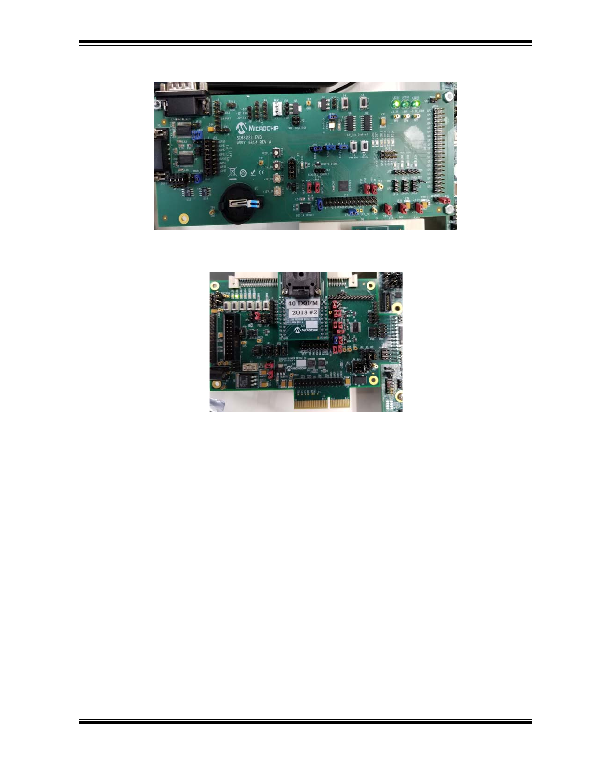
• Stock CFL S RVP with the C246PCH from Intel.
ECE1200 ESPI TO LPC BRIDGE
EVALUATION BOARD USER’S GUIDE
• SCH3223 board
2020 Microchip Technology Inc. DS50002972A-page 10
Page 11
Hardware and Software Requirements
• ECE1200 board
• RS232 DB-9 serial loopback plug
See section Section 3.2 “DP9 Loopback Plug”.
• Dediprog SF100 ISP IC Programmer
https://www.dediprog.com/product/SF100
2.1.1 Software Requirements
• Windows 10
• Microchip provided BIOS for base-lining, outimage_1x_20mhz_noslave.bin
• Microchip provided BIOS to enable the
d_CS1.bin
• Microchip provided script for rerouting the UART resources (IO 3FX and IRQ4) from the
onboard MEC14XX to the external SCH3223 via the ECE1200
• Terminal emulator software, such as Tera Term
2.1.1.1 REFERENCES
The following documents should be referenced when using this application note. Please contact
your Microchip representative for availability.
• https://www.microchip.com/wwwproducts/en/ECE1200
ECE1200, outimage_1x_20mhz_noslave_ad-
2020 Microchip Technology Inc. DS50002972A-page 11
Page 12

ECE1200 ESPI TO LPC BRIDGE
EVALUATION BOARD USER’S GUIDE
Chapter 3. Demo Setup
The general purpose of the demo is to show UART functionality using the onboard
UART in the MEC142X using ESPI connected via CS0, or the UART in the SC3223
using ESPI connected to the ECE1200 via CS1, which will bridge to LPC and connect
to the LPC SCH3223.
3.1 SETTING UP LOOPBACK ON THE RVP ONBOARD COM PORT HEADER
In order to baseline the system, the onboard COM port must be wired for loopback. See
Section B.1 “Setting Up Loopback on the RVP onboard COM Port Header” for
details on how to do this.
3.2 DP9 LOOPBACK PLUG
For the second phase of the demo, a DP9 loopback plug is used. See
Section B.2 “Pin-out for the DP9 Loopback Plug” for details on how to do this.
3.3 SETTING UP TERA TERM
A terminal emulator program is required for this demo. The one used for this demo is
Tera Term, and it will be described in this document. You are not restricted to Tera Term
and may use any terminal emulator that you want.
Tera Term can be downloaded at https://ttssh2.osdn.jp/. Download the zip file and
extract the contents to a directory. Then execute setup.exe and install to a directory of
your choosing. Start the program by executing ttermpro.exe.
2020 Microchip Technology Inc. DS50002972A-page 12
Page 13

ECE1200 ESPI TO LPC BRIDGE
EVALUATION BOARD USER’S GUIDE
Chapter 4. Running the Demo
The purpose of the demo is to use Tera Term to verify a single com port (COM1) will be
always selected with Tera Term. For the stock BIOS, the onboard MEC142X is used
for COM1. For the modified BIOS, with the board modifications and a script being run
to manipulate various registers on the RVP, COM1 resides in the SCH3223.
4.1 STEP 1: SERIAL COMMUNICATIONS USING THE ONBOARD 142X
• First, install a terminal emulator. For this demo, Tera Term is used. See
Section 3.3 “Setting Up Tera Term” on how to install it.
• Then, wire the onboard COM header for loopback. See Section 3.1 “Setting Up
Loopback on the RVP onboard COM Port Header”.
• Start Tera Term and you should see the following:
• Select ‘Serial’ and the desired COM port and press ‘OK’.
2020 Microchip Technology Inc. DS50002972A-page 13
Page 14

ECE1200 eSPI to LPC Bridge Evaluation Board User’s Guide
• Type characters and see that they are echoed. See below.
Note: If desired, the loopback connector can be removed and when you
type, characters will no longer be echoed. This will prove the COM port
being used is the onboard COM PORT.
4.2 STEP 2: MODIFY STOCK BOARD TO SUPPORT ESPI CONNECTIVITY TO THE J9G2 HEADER
The below rework will preserve ESPI connectivity to the MEC142X, but will also bring
the ESPI signals to header J9G2 to allow connection the ECE1200 board.
Rework on Intel CFL RVP to bring ESPI signals to the ESPI Header.
• Stuff R9G1 with 0 Ohm
• Stuff R9G4 with 0 Ohm
• Stuff R9G13 with 0 Ohm
• Stuff R9G16 with 0 Ohm
DS50002972A-page 14 2020 Microchip Technology Inc.
Page 15

Running the Demo
• Stuff R9G19 with 0 Ohm
• Stuff R9F26 with 0 Ohm
• Empty R9G26
• Stuff R9G27 with 15 Ohm resistor for ESPI_CLK
• Populate R9F34 with a zero ohm resistor
4.3 STEP 3: RERUN TEST ON THE MODIFIED BOARD USING ONBOARD 142X TO MAKE
SURE BOARD CHANGES HAVEN’T BROKEN ANYTHING
Execute the Tera Term test described in Section 4.1 “Step 1: Serial Communications Using the onboard 142X” to make sure everything is still in working order.
4.4 STEP 4: LOAD BIOS OUTIMAGE_1X_20MHZ_NOSLAVE.BIN WITH DEDIPROG USING CONNECTOR J7H1
It is strongly recommended that the onboard STOCK BIOS be "ripped" (copied) into a
file using the DEDIPROG before loading any new BIOS. This will allow you to restore
the board to STOCK condition if required.
This BIOS is a simple modification of the Stock BIOS. It restricts ESPI bus width to 1X
and speed to 20mhz due to the challenges of connecting the ECE1200 board to a
header.
To flash the BIOS, use the Dediprog flash programmer and program the provided BIOS
file outimage_1x_20mhz_noslave.bin.
RVP should be powered down when loading a BIOS with DEDIPROG.
4.5 STEP 5: RERUN TERA TERM TEST
Boot to Windows. On the board modified in Section 4.4 “Step 4: Load BIOS outimage_1x_20mhz_noslave.bin with Dediprog Using Connector J7H1”, using
onboard 142X, execute the Tera Term test as in Section 4.1 “Step 1: Serial Communications Using the onboard 142X” to make sure loading the new BIOS hasn’t bro-
ken anything.
4.6 STEP 6: LOAD BIOS OUTIMAGE_1X_20MHZ_NOSLAVE_ADD_CS1.BIN WITH DEDIPROG USING CONNECTOR J7H1
This BIOS is a simple modification of the Stock BIOS. It restricts the ESPI bus width to
1X and speed to 20mhz due to the challenges of connecting the ECE1200 board to a
header. This BIOS enables CS1, and without a ECE1200 EVB plugged into header
J9G2, RVP will not POST.
To flash the BIOS, use the Dediprog flash programmer and program the provided BIOS
file outimage_1x_20mhz_noslave_add_CS1.bin.
2020 Microchip Technology Inc. DS50002972A-page 15
Page 16

ECE1200 eSPI to LPC Bridge Evaluation Board User’s Guide
4.7 STEP 7: PLUG THE ECE1200 EVB INTO HEADER J9G2
Plug the ECE1200 EVB into the header J9G2 as seen below.
Before powering up with new BIOS, plug the SCH3223 board into the ECE1200 board
via the LPC male and female connector, then plug the ECE1200 into the RVP via the
J9G2 header. As received from MCHP, the SCH3223 and ECE1200 should be properly jumper-ed.
Turn on the power and the board should boot to Windows. Once the ECE1200 is being
used, all power cycling of the board should be done via the external supply by mechanically turning the supply off and on. Typically turning the supply mechanically on will
allow the system to boot. To turn it off, shut down from windows, then turn off the power
supply and wait for all LEDS on RVP to go off before turning back on (takes about ten
seconds).
4.8 STEP 8: RERUN TERA TERM TEST
From within Windows, test with Tera Term communicating to a second test PC as in
Section 4.1 “Step 1: Serial Communications Using the onboard 142X”. This will be
using the onboard 142X.
4.9 STEP 9: RUN RVP.EXE
Place the files related to the script in a directory on the Windows 10 platform
(corefiles.dll, LibFT260-64.dll, LibFT4222-64, mcp2221_dll_um_x64.dll, and
RVP.exe). Right click on RVP.exe and run as administrator.
A small dialog will come up with a single button called "Test1", press it and a pop up
will occur indicating that the 14XX was found at 0x2E.
Close the pop up and the dialog and run Tera Term.
This will reconfigure the PCH, RB, onboard 142X, and SCH3223 such that IO
addresses 0x3FX and IRQ4 get routed to SCH3223 instead of 142X.
DS50002972A-page 16 2020 Microchip Technology Inc.
Page 17

Running the Demo
4.10 STEP 10: CONNECT THE LOOPBACK PLUG TO SCH3223, AND VERIFY TERA TERM IS
WORKING
Connect the loopback plug, as described in section Section 3.2 “DP9 Loopback
Plug”, to the SCH3223, as seen below. And rerun the Tera Term test to verify that it’s
working.
Note: If desired, the loopback connector can be removed and when you type, characters
will no longer be echoed. This will prove the COM port being used is the SCH3223
COM PORT.
2020 Microchip Technology Inc. DS50002972A-page 17
Page 18

ECE1200 ESPI TO LPC BRIDGE
EVALUATION BOARD USER’S GUIDE
Appendix A. Troubleshooting
This section details how to troubleshoot any potential issues that may occur.
No POST codes:
The most common way for the PORT80 display not to power up is if the outimage_1x_20mhz_noslave_add_CS1.bin BIOS is being used but the ECE1200 board
isn’t plugged into J9G2. Make sure with the outimage_1x_20mhz_noslave_add_CS1.bin BIOS that the ECE1200 board is plugged into J9G2.
If the ECE1200 board is plugged into J9G2 and there is still no PORT80 display activity
with the outimage_1x_20mhz_noslave_add_CS1.binBIOS, then load the STOCK
BIOS or the outimage_1x_20mhz_noslave.bin as a baseline.
POST codes but no video:
In general, if POST codes are happening, but there is no video, a PCIe video card can
be used. This often fixes this issue.
No characters in Tera Term:
Put a scope probe on the appropriate TX/RX loopback pin for either the onboard loopback or the SCH3223 loopback connector and see if there is any activity when a key is
pressed.
Teraterm fails to show characters when typing:
Make sure the appropriate loopback connector is installed for either on board UART or
external ECE1200/SCH3223 UART. Please see Section 3.1 “Setting Up Loopback
on the RVP onboard COM Port Header” and Section 3.2 “DP9 Loopback Plug”.
2020 Microchip Technology Inc. DS50002972A-page 18
Page 19

ECE1200 ESPI TO LPC BRIDGE
EVALUATION BOARD USER’S GUIDE
Appendix B. Pin-Outs for the Loopback Plugs
B.1 SETTING UP LOOPBACK ON THE RVP ONBOARD COM PORT HEADER
The COM header (J9B7) is located on the lower right as seen in the image below.
2020 Microchip Technology Inc. DS50002972A-page 19
Page 20

ECE1200 eSPI to LPC Bridge Evaluation Board User’s Guide
1
3(RX)
5(TX)
7
9
2
6(CTS)
8
10
4(RTS)
How to Loopback the Onboard COM Header
ToloopbacktheonboardCOMheader:
‐Connectthereceiveandtransmitpins(3‐5)
‐Connecttherequesttosendandcleartosendpins(4‐6)
The pin-out is detailed below.
Below is an image of the header wired for loopback.
The loopback wires can be removed to show that Tera Term stops working. This will
prove that the onboard MEC142X is being used for COM1.
DS50002972A-page 20 2020 Microchip Technology Inc.
Page 21

Pin-Outs for the Loopback Plugs
15
69
DB‐9Pin EIAabbreviation Description
1 DCD Datacarrierdetect
2RXDReceivedata
3TXDTransmitdata
4DTRDataterminalready
5GNDSignalground
6 DSR Datasetready
7 RTS Requesttosen d
8CTSCleartosend
9RIRingIndicator
How to Construct an RS232 Loopback Plug
TomakeanRS232loopbackplug:
‐Connectthereceiveandtransmitpins(2‐3)
‐Connecttherequesttosendandcleartosendpins(7‐8)
‐Connectdatacarrier detect,datasetread yanddata
terminalready(1,6&4)
B.2 PIN-OUT FOR THE DP9 LOOPBACK PLUG
To construct an RS232 loopback plug used in this demo see below.
FIGURE 1: LOOPBACK PLUG PIN-OUT
2020 Microchip Technology Inc. DS50002972A-page 21
Page 22

ECE1200 ESPI TO LPC BRIDGE
EVALUATION BOARD USER’S GUIDE
Appendix C. RVP J9G2 CFL Header
Below is the pin-out for the RVP J9G2 CFL header.
2020 Microchip Technology Inc. DS50002972A-page 22
Page 23

Worldwide Sales and Service
AMERICAS
Corporate Office
2355 West Chandler Blvd.
Chandler, AZ 85224-6199
Tel: 480-792-7200
Fax: 480-792-7277
Technical Support:
http://www.microchip.com/
support
Web Address:
www.microchip.com
Atlanta
Duluth, GA
Tel: 678-957-9614
Fax: 678-957-1455
Austin, TX
Tel: 512-257-3370
Boston
Westborough, MA
Tel: 774-760-0087
Fax: 774-760-0088
Chicago
Itasca, IL
Tel: 630-285-0071
Fax: 630-285-0075
Dallas
Addison, TX
Tel: 972-818-7423
Fax: 972-818-2924
Detroit
Novi, MI
Tel: 248-848-4000
Houston, TX
Tel: 281-894-5983
Indianapolis
Noblesville, IN
Tel: 317-773-8323
Fax: 317-773-5453
Tel: 317-536-2380
Los Angeles
Mission Viejo, CA
Tel: 949-462-9523
Fax: 949-462-9608
Tel: 951-273-7800
Raleigh, NC
Tel: 919-844-7510
New York, NY
Tel: 631-435-6000
San Jose, CA
Tel: 408-735-9110
Tel: 408-436-4270
Canada - Toronto
Tel: 905-695-1980
Fax: 905-695-2078
ASIA/PACIFIC
Australia - Sydney
Tel: 61-2-9868-6733
China - Beijing
Tel: 86-10-8569-7000
China - Chengdu
Tel: 86-28-8665-5511
China - Chongqing
Tel: 86-23-8980-9588
China - Dongguan
Tel: 86-769-8702-9880
China - Guangzhou
Tel: 86-20-8755-8029
China - Hangzhou
Tel: 86-571-8792-8115
China - Hong Kong SAR
Tel: 852-2943-5100
China - Nanjing
Tel: 86-25-8473-2460
China - Qingdao
Tel: 86-532-8502-7355
China - Shanghai
Tel: 86-21-3326-8000
China - Shenyang
Tel: 86-24-2334-2829
China - Shenzhen
Tel: 86-755-8864-2200
China - Suzhou
Tel: 86-186-6233-1526
China - Wuhan
Tel: 86-27-5980-5300
China - Xian
Tel: 86-29-8833-7252
China - Xiamen
Tel: 86-592-2388138
China - Zhuhai
Tel: 86-756-3210040
ASIA/PACIFIC
India - Bangalore
Tel: 91-80-3090-4444
India - New Delhi
Tel: 91-11-4160-8631
India - Pune
Tel: 91-20-4121-0141
Japan - Osaka
Tel: 81-6-6152-7160
Japan - Tokyo
Tel: 81-3-6880- 3770
Korea - Daegu
Tel: 82-53-744-4301
Korea - Seoul
Tel: 82-2-554-7200
Malaysia - Kuala Lumpur
Tel: 60-3-7651-7906
Malaysia - Penang
Tel: 60-4-227-8870
Philippines - Manila
Tel: 63-2-634-9065
Singapore
Tel: 65-6334-8870
Taiwan - Hsin Chu
Tel: 886-3-577-8366
Taiwan - Kaohsiung
Tel: 886-7-213-7830
Taiwan - Taipei
Tel: 886-2-2508-8600
Thailand - Bangkok
Tel: 66-2-694-1351
Vietnam - Ho Chi Minh
Tel: 84-28-5448-2100
EUROPE
Austria - Wels
Tel: 43-7242-2244-39
Fax: 43-7242-2244-393
Denmark - Copenhagen
Tel: 45-4485-5910
Fax: 45-4485-2829
Finland - Espoo
Tel: 358-9-4520-820
France - Paris
Tel: 33-1-69-53-63-20
Fax: 33-1-69-30-90-79
Germany - Garching
Tel: 49-8931-9700
Germany - Haan
Tel: 49-2129-3766400
Germany - Heilbronn
Tel: 49-7131-72400
Germany - Karlsruhe
Tel: 49-721-625370
Germany - Munich
Tel: 49-89-627-144-0
Fax: 49-89-627-144-44
Germany - Rosenheim
Tel: 49-8031-354-560
Israel - Ra’anana
Tel: 972-9-744-7705
Italy - Milan
Tel: 39-0331-742611
Fax: 39-0331-466781
Italy - Padova
Tel: 39-049-7625286
Netherlands - Drunen
Tel: 31-416-690399
Fax: 31-416-690340
Norway - Trondheim
Tel: 47-7288-4388
Poland - Warsaw
Tel: 48-22-3325737
Romania - Bucharest
Tel: 40-21-407-87-50
Spain - Madrid
Tel: 34-91-708-08-90
Fax: 34-91-708-08-91
Sweden - Gothenberg
Tel: 46-31-704-60-40
Sweden - Stockholm
Tel: 46-8-5090-4654
UK - Wokingham
Tel: 44-118-921-5800
Fax: 44-118-921-5820
DS50002972A-page 23 2020 Microchip Technology Inc.
02/28/20
 Loading...