

Page 1
Low-Cost Development Tools
Low-Cost Development Tools Guide
For use with Analog and Interface Products, 8-bit PIC
Microcontrollers (MCUs), 16-bit MCUs and dsPIC® Digital Signal
Controllers (DSCs), Memory and K
Microchip offers a wide range of
development tools – all designed
to help you achieve faster time to
market. For a complete listing of
Microchip products and their
corresponding users guides,
data sheets and technical
information, visit our web site at:
www.microchip.com
Fall 2006
Getting Started Products ...........1-2
Linear Products............................2
Interface Products .....................3-5
Mixed Signal Products ............... 5-6
Power-Management Products ..... 6-9
Thermal Management
Products .............................. 9-10
PIC® MCU and dsPIC® DSC
Demonstration Boards ........10-11
Blank Analog Evaluation PCBs .....11
Programmers .............................12
Analog Software Tools ................12
MCU Software Tools ...................12
dsPIC® DSC Evaluation
Software Tools ........................13
EELOQ
®
Getting Started Products
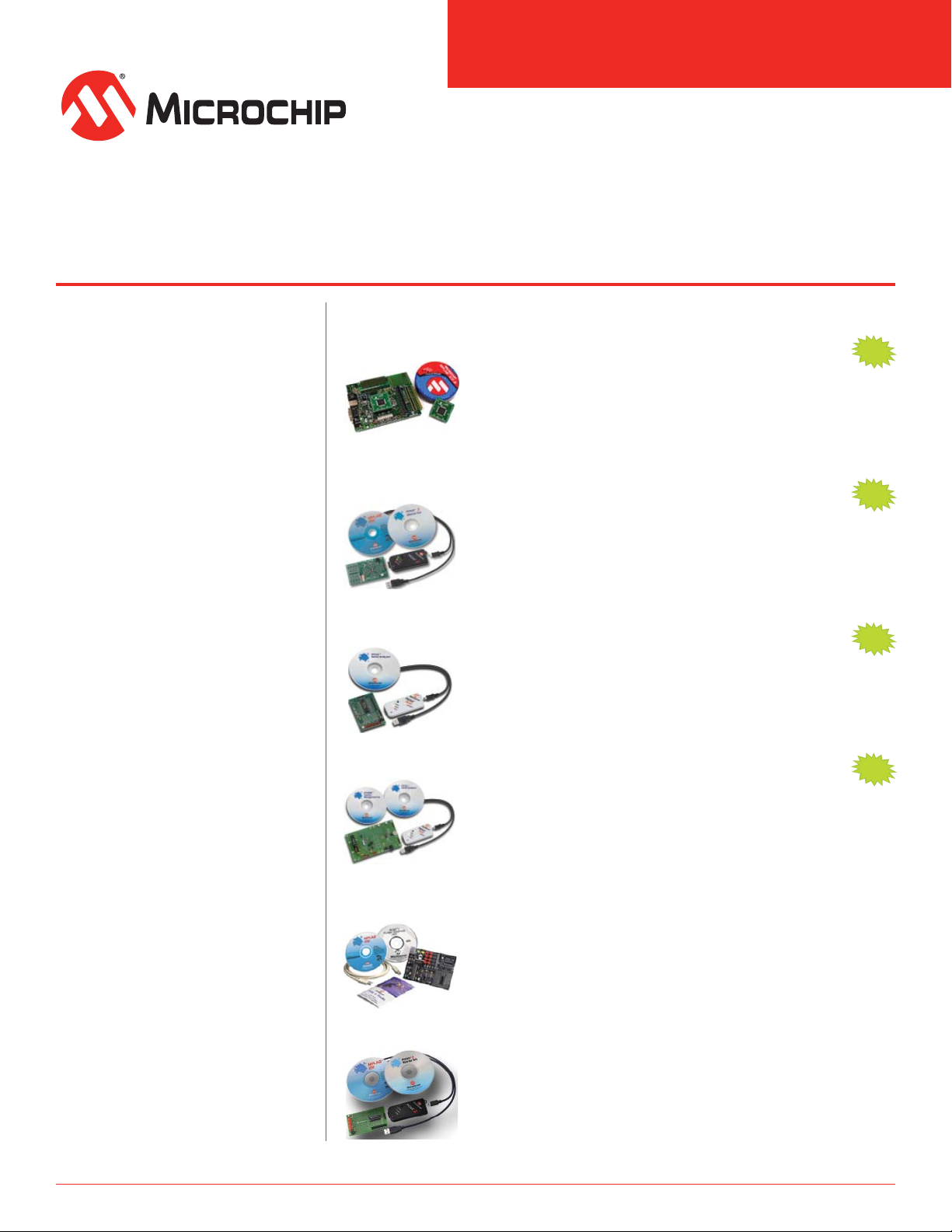
Explorer 16 Starter Kit
Part Number: DV164033
A complete set of tools for application development using the PIC24F,
PIC24H and dsPIC33F 16-bit families. The kit includes MPLAB® ICD 2,
Explorer 16 Development Board, 9V universal power supply, serial
cable and both a PIC24FJ128GA010 and dsPIC33F256GP710 PIM.
Tutorials, user manuals, MPLAB® IDE and MPLAB C30 C Compiler
(student edition) are included.
PICkit™ 2 Debug Express
Part Number: DV164121
Allows in-circuit programmer/debugger functions on selected PIC®
MCUs. This provides the ability to run, examine and modify the program,
while the MCU is embedded in the hardware, thereby assisting in
debugging the firmware and hardware together. Programs can be run,
stopped and single-stepped. Includes 44-pin demo board. Requires
MPLAB® IDE version 7.40 or later.
PICkit™ Serial Analyzer
Part Number: DV164122
A low-cost development kit with an easy-to-use interface. Includes a
development board containing Microchip’s 28-pin PIC16F886 Flash
microcontroller. This MCU contains fi rmware to emulate several
functions typically found in serial systems. The PICkit™ Serial Analyzer
can be used to exercise these functions and display the data.
PICDEM™ System Management Kit
Part Number: DM164123
An inexpensive demonstration and training tool that allows
communication between a PC and the serial protocol of the system
being tested. Integrates the functions of a dedicated Real-Time Clock
(RTC), serial EEPROM, thermal management controller and Analogto-Digital Converter (ADC) into a single PIC® microcontroller. Ideal for
designing applications with a variety of integrated peripherals.
Products.
®
NEW
NEW
NEW
NEW
PICkit™ 1 Flash Starter Kit
Part Number: DV164101
A low-cost starter development kit with an easy-to-use interface for
programming Microchip’s 8-/14-pin Flash PIC® MCUs. The kit includes
everything needed to program, evaluate and develop applications.
Seven tutorials with all source code files are furnished.
PICkit™ 2 Starter Kit
Part Number: DV164120
PICkit™ 2 is small, easy-to-use starter kit that enables users to start
writing code and programming with PIC® MCUs. Features full-speed
USB support and firmware upgradeability in a low-cost tool. Includes a
low pin-count demo board. Upgrade firmware for debugger function.
Page 2
Low-Cost Development Tools Guide
PICDEM™ HPC Explorer Board
Part Number: DM183022
This low-cost demo board is used to evaluate
the performance of High Pin Count (HPC)
8-bit PIC18F series microcontrollers. The
board features a PIC18F8722 MCU, which
is the superset of the entire 64- and 80-pin
PIC18FXXXX general purpose family. A daughter
board (mezzanine) is also part of the kit and allows different
processors sharing the same pin out to be mounted and tested on
the explorer board.
Signal Analysis PICtail™ Daughter Board
Part Number: AC164120
This board works as an extension to the
PICkit™ 1 Flash Starter Kit. When combined
with PICkit 1 firmware version 2.0.0 or later
and the signal-analysis PC program, the board
performs signal-analysis capabilities such as:
real-time strip chart, oscilloscope, Fast Fourier
Transformation (FFT), histogram and programming. The board
comes populated with a PIC16F684 and two 25LC640
SPI-compatible serial EEPROM memory devices.
PIC10F 6L SOT-23 to 8P DIP Adapter Kit
Part Number: AC163021
This is a kit consisting of (5) PIC10F206
SOT-23 devices, (5) pin scramble boards and
DIP pins. Once assembled, this makes the
SOT-23 look like a standard 8-pin DIP and can
be used directly in standard development tool
sockets. This kit should be used only for early
evaluation.
SEEVAL® 32 Serial EEPROM Evaluation Kit
Part Number: DV243002
An evaluation and programming system
supporting all Microchip Serial EEPROMS
including future devices. Using a ZIF socket,
standard DIP sockets are directly supported.
The SEEVAL 32 gives the designer the ability
to read, write or erase any byte, page or entire array, and to display,
save or load this data as a file. SEEVAL 32 provides support for
Windows® XP, Windows ME, Windows 2000, Windows NT® 4.0 and
Windows 95/98.
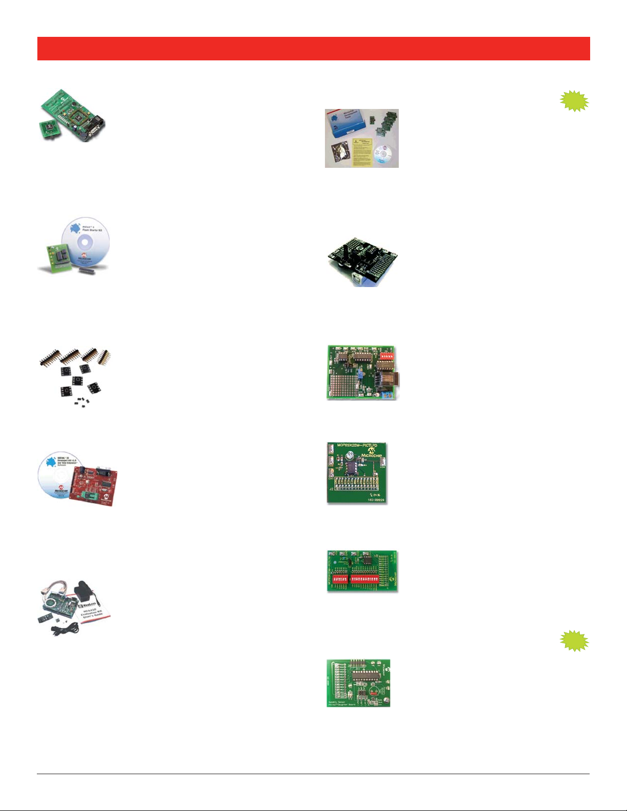
KEELOQ® Evaluation Kit II
Part Number: DM303006
This kit demonstrates the capabilities of the
code-hopping technology used in security
systems such as garage door openers, auto
keyless entry, etc. for secure access and/or
authentication. It includes a main board and
2 transmitters to demonstrate encoders and decoders. The fully
functional kit allows a short learning cycle into the technology.
Linear Products
MCP6271 Active Filter Evaluation Kit
Part Number: MCP6XXXDM-FLTR
This kit supports active filters designed by
FilterLab® V2.0. These filters are all pole and
are built by cascading first and second order
sections. The kit includes: one PCB designed
printed circuit boards, four PCBs that support active filter designs
with filter order between n = 1 and 8 (output test point for lab
equipment provided) and op amps, zero ohm jumpers, resistors and
capacitors that can be used to help build filters
to provide mid-supply biasing to the other
.
MCP6S22 PGA PICtail™ Demonstration Board
Part Number: MCP6S22DM-PICTL
This board evaluates/demonstrates
Microchip’s MCP6S21/2/6/8 Programmable
Gain Amplifier (PGA) family. Interface this
board with the PICkit™ 1 Flash Starter Kit to
the PIC® MCU and PGA devices, while allowing modification and
development of firmware for specific requirements.
demonstrate firmware integration between
MCP6S2X PGA Evaluation Board
Part Number: MCP6S2XEV
Provides a versatile selection of input
channels and gains to evaluate device
performance. Board supports multiple input
signal sources. Two devices can be cascaded
to produce gain to 1024 V/V.
MCP6SX2 PGA Photodiode PICtail™
Demonstration Board
Part Number: MCP6SX2DM-PCTLPD
Opens possibilities to process other sensor
signals. Increases the number of PIC® MCU
I/O pins available for other purposes. Features
a PNZ334 photo-diode, MCP6001U op amp and
MCP6S22 and MCP6S92 Programmable Gain
Amplifiers (PGA).
MCP6SX2 PGA Thermistor PICtail™
Demonstration Board
Part Number: MCP6SX2DM-PCTLTH
Features MCP6S22 and MCP6S92 PGAs.
Helps overcome non-linear response of the
on-board NTC thermistor. Opens possibilities
increasing the number of PIC® MCU I/O pins available for other
purposes.
of temperature-correcting another sensor, and
Humidity Sensor PICtail™
Demonstration Board
Part Number: PIC16F690DM-PCTLHS
This board supports the capacitive humidity
sensor application note AN1016. It measures
the capacitance of a relative humidity
sensor plugged into the board. The on-board
calculated relative humidity (RH) to a PC for display. The board can
also measure small capacitors in different ranges of values using a
dual slope integration method.
microcontroller sends the measured and
NEW
NEW
2
Page 3
Low-Cost Development Tools Guide
Interface Products
GPIO Expander Keypad and
LCD Demonstration Board
Part Number: GPIODM-KPLCD
The GPIO Expander Keypad and LCD Demo Board is
designed to demonstrate the use of the MCP23S08/17
(SPI interface) and the MCP23008/17 (I
devices in a keypad and LCD example. The MCP23X17
(16-bit) devices interface to a 2x16 LCD module and
the MCP23X08 (8-bit) devices interface to a 4x4 keyed
matrix.
2
PICDEM™ CAN-LIN 1 Demonstration Board
Part Number: DM163007
Microchip offers three PICDEM CAN-LIN Demo
Boards to support different PIC® MCUs. All
demonstrate the main features of the devices,
CAN module. The boards also employ a LIN sub-network using the
PIC16C43X and PIC18F320 device families.
PIC18C658, 84-pin PLCC PIC18C858 devices and 20-pin PDIP
PIC16C432 with integrated LIN Bus transceiver.
especially those features of the integrated
Supports: 68-pin PLCC
PICDEM™ CAN-LIN 2 Demonstration Board
Part Number: DM163011
PICDEM CAN-LIN 2 supports: 28-pin SDIP
PIC18F258 and PIC18F268X devices, 40-pin
PDIP PIC18F458 and PIC18F468X devices and
20-pin PDIP PIC16C432 with integrated LIN Bus
transceiver.
PICDEM™ CAN-LIN 3 Demonstration Board
Part Number: DM163015
PICDEM CAN-LIN 3 supports: 64-pin TQFP
PIC18F6680, 80-pin TQFP PIC18F8680 devices,
20-pin SSOP PIC18F1320 and MCP201 LIN Bus
transceiver.
PICDEM™ LCD Demonstration Board
Part Number: DM163028
Demonstrates the main features of the LCD
Flash 28-, 40-, 64- and 80-pin PIC® MCUs
with power-management features. The board
is populated with the PIC18F8490 and other
A sample LCD glass display is included for custom prototyping. The
PICDEM LCD kit provides tutorial firmware, which is included in the
preprogrammed devices.
devices are supported via a transition socket.
PICDEM™ LCD Plug-In Modules
Part Number: MA160011
A simple and inexpensive method to utilize
the PICDEM LCD platform for development with
PIC16F913/914/916/917/946. The plug-in
modules kit consists of one of each of the
PIC16F913), PIC16F917 module (superset of the PIC16F917) and a
PIC16F946 module.
following: a PIC16F916 module (superset of the
NEW
C™ interface)
PICDEM™ FS USB Demonstration/Evaluation Board
Part Number: DM163025
Demonstrates and evaluates the PIC18F4550
family of Flash MCUs with full-speed USB 2.0
interface. The board contains a PIC18F4550
MCU in a 44-pin TQFP package, representing
the superset of the entire family of devices.
PICDEM™ USB Demonstration Board
Part Number: DM163010
Demonstrates the PIC16C745 and PIC16C765
USB MCUs communicating to a PC using the
USB port.
PICDEM™ MSC1 Infrared (IR) Driver
NEW
Daughter Board
Part Number: AC163002
This board, in combination with the PICDEM
MSC1 Demo Board, serves as a demonstration
and evaluation kit for designing a high-power
PIC16C782. The
IR receiver, implements both receive and transmit sections of a
Pulse Width Modulation (PWM) IR remote control system.
PICtail™ Daughter Board for SD and
IR remote control transmitter using the
daughter board, in combination with the included
NEW
MMC Cards
Part Number: AC164122
This PICtail daughter board interfaces with newer
development boards that offer the PICtail and
PICtail Plus connector interface; such as the
PICDEM™ FS USB development board. This board
also interfaces with the Explorer 16 Development
Board via the PICtail Plus connector.
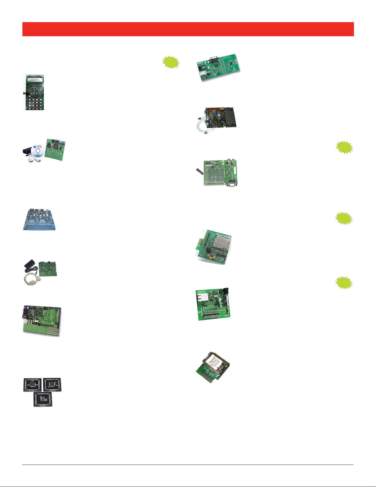
Ethernet PICtail™ Daughter Board
Part Number: AC164121
Provides a cost-effective method of evaluating
and developing Ethernet-control applications.
This board is populated with a 28-pin Ethernet
controller, which interfaces to the RJ-45 female
connector. Designed for flexibility, this board
can be plugged into the popular PICDEM™ HPC Explorer Board
(DM183022).
NEW
Ethernet PICtail™ Plus Daughter Board
Part Number: AC164123
This board provides a cost-effective method
of evaluating and developing Ethernet-control
applications. Designed for flexibility, the board
can be plugged into Microchip’s Explorer 16
is populated with a 28-pin ENC28J60 Ethernet controller, which
interfaces to the RJ-45 female connector. When used in conjunction
with the Microchip TCP/IP stack, the daughter board allows a
developer to connect any Microchip 16-bit product to an Ethernet
device.
Development Board (DM240001). The board
3
Page 4
Low-Cost Development Tools Guide
ZENA™ Network Analyzer
Part Number: DM183023
A wireless network analyzer that graphically
displays wireless network traffic following
the IEEE 802.15.4 specification on the 2.4
GHz band. Supports both the ZigBee™ and
MiWi™ protocols. In conjunction with the hardware packet sniffer,
the software can analyze complete network traffic and graphically
display decoded packets, when developing with either the ZigBee or
the MiWi protocols.
NEW
rfPIC® Development Kit 1
Part Number: DV164102
Provides design engineers with an easy way
to evaluate unidirectional remote sense
and control wireless links based on the
rfPIC12F675 and rfRXD0420/0920 devices.
Kit and consists of modular building blocks for different transmitters
and receivers that can be utilized for prototype systems or to
evaluate different options.
The kit is based on the PICkit™ 1 Flash Starter
rfPIC® Development Kit 1 Accessories
rfPIC® Transmitter Module (433.92 MHz)
Part Number: AC164101
rfPIC® Transmitter Module (315 MHz)
Part Number: AC164102
rfPIC® Receiver Module (433.92 MHz)
Part Number: AC164103
rfPIC® Receiver Module (315 MHz)
Part Number: AC164104
rfPIC® Receiver Module 5 pack (433.92 MHz)
Part Number: AC164105
rfPIC® Receiver Module 5 pack (315 MHz)
Part Number: AC164106
MCP2140 IrDA® Wireless Temp Demonstration Board
Part Number: MCP2140DM-TMPSNS
Demonstrates the MCP2140 device in a
real-world application. This design is an
example of how to integrate an IrDA® standard
port into a system.
MCP212X Developer’s Daughter Board
Part Number: MCP212XEV-DB
Evaluates and demonstrates the MCP2122 or
MCP2120 IrDA® Standard Encoder/Decoder
devices. A header allows the MCP212X
Daughter Board to be easily jumpered into
systems for development purposes. This board
also interfaces with these new low-cost PIC®
MCU demo boards: PICDEM™ HPC Explorer, PICDEM FS USB and
PICDEM LCD Demo Board.
MCP2120/2150 Infrared Developer’s Kit
Part Number: DM163008
Includes everything needed to create a system
that communicates using infrared. The kit
contains two MCP2120 developer’s boards,
enabling a complete system (transmitter and
developer’s board that can be used to set up a system to
communicate with other IrDA® standard enabled devices.
receiver) to be implemented, and a MCP2150
MCP215X Data Logger Demonstration Board
Part Number: MCP215XDM
Demonstrates the MCP2150 (or MCP2155)
IrDA® Standard Protocol Stack Controller
device in a real world application. Shows how
to integrate an IrDA standard port into an
embedded system.
MCP215X/40 Developer’s Daughter Board
Part Number: MCP215X/40EV-DB
Used to evaluate and demonstrate the
MCP2150, MCP2155 or the MCP2140 IrDA®
Standard Protocol Handler with Encoder/Decoder
devices. Headers allow the MCP215X/40
Developer’s Daughter Board to be easily
jumpered into systems for development
purposes. This board also interfaces with these new low-cost
PIC® MCU demo boards: PICDEM™ HPC Explorer, PICDEM FS USB
and PICDEM LCD Demo Board.
MCP23X08 8-bit GPIO Expander Evaluation Board
Part Number: MCP23X08EV
Demonstrates simple input/output functionality
of the MCP23008 (I
MCP23S08 (SPI interface). The system
demonstrates the simplicity of monitoring four
inputs and applying the level to associated
outputs.
MCP23X17 16-bit GPIO Expander
Evaluation Board
The system demonstrates the simplicity of monitoring four pins
configured as inputs and applying a predetermined pattern on LEDs
connected to the remaining 12 pins configured as outputs.
Part Number: MCP23X17EV
This board demonstrates the simple input/
output functionality of the MCP23017 (I
interface) and the MCP23S17 (SPI interface).
2
C™ interface) and the
2
NEW
C™
MCP250XX CAN I/O Expander Developer’s Kit
Part Number: DV250501
Supporting CAN V2.0B active with bus rates up
to 1 Mb/s, this kit includes everything needed
to demonstrate, design, develop and configure a
CAN node using the MCP250XX CAN I/O Expander
family of products.
MCP2510/2515 CAN Developer’s Kit
Part Number: DV251001
To speed up software development and enable
introduction of CAN to those who are unfamiliar
with the protocol, Microchip offers a unique
combination of a software development tool and
a CAN message/communication tool called the
MCP2515/2510 CAN Developer’s Kit.
4
Page 5
Low-Cost Development Tools Guide
MCP2515 CAN Controller PICtail
™
Demonstration Board
Part Number: MCP2515DM-PCTL
This demo board implements a simple CAN
bus using two nodes. One using the MCP2515
Stand Alone CAN controller and the other
using the MCP25020 CAN I/O Expander. Each
one output (LED). The boards demonstrate a simple, inexpensive
implementation of a CAN bus.
node utilizes one input (push button) and
Mixed Signal Products
MCP3XXX Single/Dual ADC MXDEV
Daughter Board
Part Number: DV3201A
Supports MCP3001, MCP3002, MCP3201
and MCP3202 stand-alone A/D converters.
Used with the MXDEV Driver Board (available
separately).
MCP3204/08 MXDEV® Daughter Board
Part Number: DV3204A
Supports MCP3004, MCP3008, MCP3204
and MCP3208 stand-alone A/D converters.
Used with the MXDEV Driver Board (available
separately).
MCP3221 12-bit A/D PICtail™ Demonstration Board
Part Number: MCP3221DM-PCTL
Designed to demonstrate the MCP3221 device
using DataView™ Windows software for a
graphical real-time data analysis from the board
through USB. This demo board can also be used
for firmware development to the MCP3221 device
using the PICkit™ 1 Flash Starter Kit.
MCP355X Tiny Application Sensor
Demonstration Board
Part Number: MCP355XDM-TAS
This 1” x 1” board is designed to demonstrate
the performance of the MCP3550/1/3 devices
in a simple low-cost application. The circuit uses
a ratiometric sensor configuration and uses the
system power supply as the voltage reference.
®
NEW
MCP3551 Delta-Sigma ADC Demonstration Board
Part Number: MCP3551DM-PCTL
Designed to demonstrate the MCP3551 device’s
22-bit Delta-Sigma Analog-to-Digital Converter (ADC)
performance using DataView™ software installed on a
PC. This demo board can be used with MPLAB
PICkit™ 1 Flash Starter Kit or PICkit™ 2 for developing
demonstration/evaluation firmware.
®
ICD 2,
MCP3905 Energy Meter Evaluation Board
Part Number: MCP3905EV
This evaluation board is designed to test out a
variety of energy meter designs. On the input side
high-voltage line and load AC-plug headers are
included, along with mounting holes for shunts,
for wiring. On the output side a large prototype area is included
along with optical isolation and a standard PICtail™ header for
experiments with a variety of PIC
designs.
current transformers and screw-type connections
®
MCU-based energy meter
MCP3905 Energy Meter Reference Design
Part Number: MCP3905RD-PM1
A stand-alone low-cost energy meter that
can act as either a stand alone energy
LCD MCU-based meters. This design is specified with an energy
measurement error of 0.1% typical across 1:500 dynamic range
for high accurate energy meter designs and is compliant with EMC
requirements per energy metering standards IEC62053 and legacy
IEC61036, IEC1046 and IEC687.
MCP4XXX Digital Potentiometer
meter, or as the analog front end design for
NEW
Daughter Board
Part Number: MCP4XXXDM-DB
This board allows evaluation of the MCP42XXX
and MCP402X Digital Potentiometers. The
MCP42XXX are dual digital potentiometer devices
that have the same characteristics as the single
The MCP402X devices are non-volatile and have similar
characteristics to their volatile memory versions (MCP401X).
The board supports two MCP42XXX devices to allow the resistor
networks to be “stacked” and form a programmable windowed
digital potentiometer. The board also has a voltage doubler device
(TC1240A), which can be used to show the WiperLock™ Technology
feature of the MCP4021.
digital potentiometer devices (MCP41XXX).
MCP355X Sensor Applications
NEW
Developer’s Board
Part Number: MCP355XDV-MS1
This board allows for easy design of high
resolution systems such as weigh scale,
temperature sensing or other small signal
circuits. The reference design includes LCD display firmware that
performs all the necessary functions including ADC sampling,
USB communication for PC data analysis, LCD display output, zero
cancellation, full scale calibration and units display in gram (g),
kilogram (kg) or ADC output units.
systems requiring precise signal conditioning
MCP402X Non-Volatile Digital Potentiometer
Evaluation Board
Part Number: MCP402XEV
This low-cost board enables user’s to exercise all
of the features of the MCP401X and MCP402X
devices. Kit includes one populated and one
unpopulated PCB. The populated board has
an MCP4021-103E/SN digital potentiometer
configured as a “windowed” potentiometer using a 2.5 kΩ pull-up
and a 2.5 kΩ pull-down resistor. The PCB supports the 8-pin SOIC,
SOT-23-6 and SOT-23-5 package variations. The unpopulated PCB
allows user’s to build the exact combination of components their
application requires.
5
Page 6

Low-Cost Development Tools Guide
MCP42XXX Digital Potentiometer Evaluation Board
Part Number: DV42XXX
Includes an evaluation board, prototype board,
RS-232 cable, 9V DC power supply, MXLAB®
software, digital potentiometers and PIC® MCU.
Used with the MXDEV® Driver Board (available
separately).
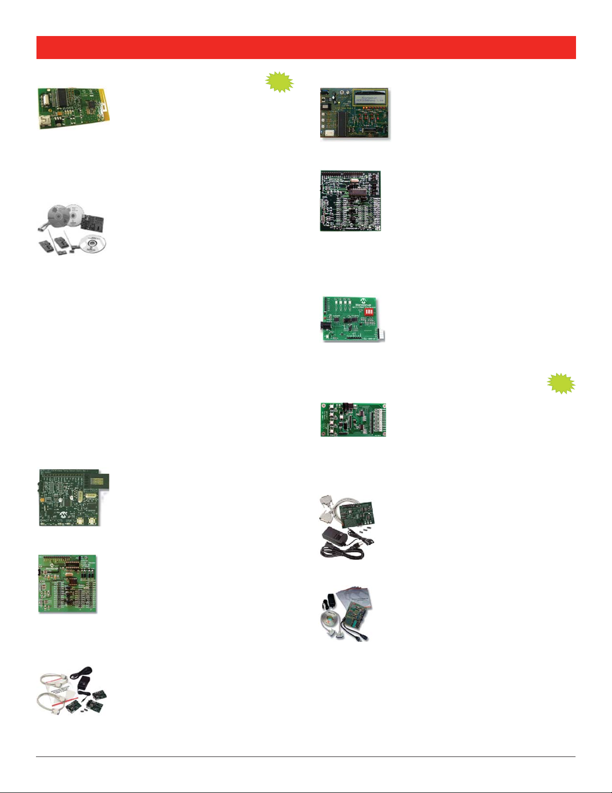
PICDEM™ MSC1 Delta-Sigma ADC Daughter Board
Part Number: AC163003
In combination with the PICDEM MSC1 Demo
Board, this board serves as a demonstration and
evaluation kit for designing high-resolution Delta
Sigma Analog-to-Digital Converters using the
PIC16C781/782.
PICDEM™ MSC1 Flow Rate Sensor Daughter Board
Part Number: AC163004
This board, in combination with the
PICDEM MSC1 Demo Board, is a complete
demonstration kit for a high sensitivity
hot-wire anemometer-styled fl ow rate sensor
using the PIC16C782.
PICDEM™ MSC1 Mixed Signal Controller
Demonstration Board
Part Number: DM163012
The PICDEM MSC1 with its PC-based
Graphical User Interface (GUI) software
serves as a stand-alone development and
evaluation tool for the PIC16C781/782
MCUs, or as a user interface to the
peripherals.
Mixed-Signal PICtail™ Demonstration Board
Part Number: MXSIGDM
Quickly and accurately evaluates performance
of Microchip DACs, A/D converters, LDOs,
V
REFs and operational amplifiers. Interfaces to
a PIC16F767 for stand-alone operation. Supports many Microchip
mixed-signal devices (surface mount footprint).
the PICkit™ 1 Flash Starter Kit. Can use with
Power-Management Products
MCP1252 Charge Pump Backlight
Demonstration Board
Part Number: MCP1252DM-BKLT
Demonstrates the use of a charge pump
device in an LED application and acts as a
platform to evaluate the MCP1252 device
in general. Light intensity is controlled
A PIC10F206 MCU provides an enable signal to the MCP1252
and accepts a push-button input that allows the white LEDs to be
adjusted to five different light intensities.
MCP1256/7/8/9 Charge Pump
Evaluation Board
MCP1601 Buck Regulator Evaluation Board
MCP1612 Synchronous Buck Regulator
Evaluation Board
uniformly through the use of ballast resistors.
NEW
Part Number: MCP1256/7/8/9EV
An evaluation and demonstration tool for the
MCP1256/7/8/9 regulated 3.3V, low-ripple charge
pumps with low-operating current Sleep mode or
Bypass mode. The board is set-up to evaluate
simple, stand-alone, DC-to-DC conversion. The
two evaluation circuits provided, demonstrate the
versatility of the MCP1256/7/8/9 family.
Part Number: MCP1601EV
For both battery-powered and distributedpower applications. Operates over a 2.7V to
5.5V input range while delivering 500 mA of
output current.
Part Number: MCP1612EV
Features a 1A 1.4 MHz synchronous buck
regulator in two buck converter applications. The
applications use the 8-lead MSOP and 8-lead DFN
packages respectively. Selectable output voltages
and a shutdown terminal are available on each
converter.
MXDEV® Analog Evaluation System
Part Number: DVMCPA
Versatile, easy-to-use system helps evaluate
mixed-signal products. Includes the
DVMCPA MCP Driver Board, which provides
data acquisition and analysis/display in a
Windows® environment.
6
MCP1630 Automotive Input Boost Converter
NEW
Demonstration Board
Part Number: MCP1630DM-DDBS1
Demonstrates the MCP1630/V high-speed
pulse width modulator used for automotive
applications. When used with a microcontroller,
the MCP1630/V devices control the power
system duty cycle to provide regulated output
voltage. The programmable PIC12F683
pulses at switching frequency of 500 kHz and set maximum duty
cycle. The user may also modify or develop their own firmware
routines to further evaluate the MCP1630/V devices in this
application.
microcontroller is used to provide oscillator
Page 7

Low-Cost Development Tools Guide
MCP1630 Coupled Inductor Boost
NEW
Demonstration Board
Part Number: MCP1630DM-DDBS2
This board demonstrates Microchip’s highspeed Pulse Width Modulator (PWM) used in
a coupled inductor design. When used with a
programmable PIC12F683 microcontroller, the
MCP1630 device controls the power system
duty cycle to provide different regulated output
pulses, reference voltage, output voltage selection and ON/OFF
of converter using push button S1. The user can also modify
or develop their own firmware routines to further evaluate the
MCP1630 device in this application.
MCP1630 Automotive Input, Triple Output
Converter Demonstration Board
Part Number: MCP1630DM-DDBK4
Demonstrates a high-speed Pulse Width Modulator (PWM) used
for automotive application. When used in conjunction with a
microcontroller, the MCP1630 will control the power system
duty cycle to provide three regulated output voltages of 3.3V
at 1.2A, 1.2V at 600 mA and 4.7V at 150 mA. The PIC12F683
microcontroller is used to provide reference voltage, ON/OFF of
Converter using push button SW1 and oscillator pulses at switching
frequency of 250 kHz. The MCP1630 generates duty cycle based
on various external inputs. External signals include the input
oscillator pulses, reference voltage from PIC12F683 device, and the
feedback voltage. The user can also modify or develop their own
firmware routines to further evaluate the MCP1630 device in this
application.
voltages from 15V-40V, generates oscillator
NEW
MCP1630 +12V in Dual-Output Buck Converter
Reference Design
Part Number: MCP1630RD-DDBK1
This demo board is a dual-output
programmable power supply capable of 20A
per output. Both outputs switch at 500 kHz
180° out of phase while powered from a +12V
output voltage, power good output indication, sequencing,
overcurrent and overtemperature.
input source. Features include programmable
MCP1630 1A Bias Supply Demonstration Board
Part Number: MCP1630DM-DDBK1
This demo board is used to evaluate Microchip’s
MCP1630 used in a SEPIC power converter
application. The demo board is capable of
providing a regulated output from an input
voltage of 9V. The regulated output voltage is
for an output load range of 0A to 1A. An LED indicates the
presence of output voltage.
selectable at 3.3V or 5V and remains constant
MCP1630 Li-Ion Multi-Bay Battery Charger
Reference Design
Part Number: MCP1630RD-LIC1
Used to evaluate the MCP1630 used in a SEPIC
power converter application. This charger is
capable of charging two single-cell, Li-Ion battery
packs in parallel utilizing an input voltage of 10V
to 30V (battery packs are not included).
MCP1630 Low-Cost Li-Ion Battery Charger
Reference Design
Part Number: MCP1630RD-LIC2
This board is used to evaluate the MCP1630
device used in a SEPIC power converter
applications. The charger is capable of charging
a single-cell, Li-Ion battery pack utilizing an input
voltage of 6V to 18V (battery packs are not
included).
MCP1630 NiMH Battery Charger
Demonstration Board
Part Number: MCP1630DM-NMC1
High-speed PWM interfaces to PIC16LF818,
providing a complete NiMH battery charger
with fuel gauge capability. Minimizes external
inductor, capacitor cost; performs complex
NiMH battery charger timing functions.
Protects battery circuit if a fault occurs.
MCP1650 3W White LED Demonstration Board
Part Number: MCP1650DM-LED1
Demonstrates the MCP165X Boost Controller
product family in a battery-powered white LED
application with an input voltage range of 2.0V to
4.5V.
MCP1650 Multiple White LED Demonstration Board
Part Number: MCP1650DM-LED2
The MCP1650 Multiple White LED Demo
Board uses the MCP1650 IC to power the nine
white LEDs which are connected in series. A
PIC10F202 MCU in a SOT-23-6 package is used
to provide the PWM signal to the MCP1650. It
also accepts a push button input that allows the
user to adjust the white LEDs to three different
intensities of 100%, 50% and 25%.
MCP1650 Boost Controller Evaluation Board
Part Number: MCP1650EV
Demonstrates the MCP165X Boost Controller
product family in two high-power, boostconverter applications.
7
Page 8

Low-Cost Development Tools Guide
MCP1650 SEPIC Power Supply Demonstration Board
Part Number: MCP1650DM-DDSC1
Used to evaluate Microchip’s MCP1650
boost controller in a low-power application
that requires a regulated output voltage from
an input source that can be greater than,
provided, this board generates a 5.0V output from a 3.0V to 7.0V
source.
less than or equal to the output voltage. As
MCP1726 1A LDO Evaluation Board
Part Number: MCP1726EV
This board features 1A, Low Quiescent Current
LDO Regulator in two circuits. The circuits
feature adjustable versions of the MCP1726 in
the 8-lead 3x3 DFN and 8-pin SOIC packages
respectively. Both circuits have potentiometers
voltage versions of the device can also be evaluated with this
board.
to adjust the output voltage of the LDO. Fixed
MCP7382X Li-Ion Battery Charger Evaluation Board
Part Number: MCP7382XEV
Three circuits utilizing the MCP73826,
MCP73827 and MCP73828 devices to
demonstrate simple, stand-alone, linear
charging of single cell Lithium-Ion/
Lithium-Polymer battery packs (the battery
packs are not included).
MCP73831 Evaluation Kit
Part Number: MCP73831EV
The two evaluation boards provided are set
up to evaluate simple, stand-alone, linear
charging of single cell Li-Ion/Li-Polymer battery
packs (the battery packs are not included).
Each board design provides constant current
charging followed by constant voltage charging
design provides evaluation in two package options: a SOT-23-5 and
a 8-lead 2x3 DFN for higher power handling capability.
MCP73833 Li-Ion Battery Charger
with automatic charge termination. Each board
NEW
Evaluation Board
Part Number: MCP73833EV
This evaluation and demonstration tool for
MCP73833/4 charge management controllers
provides two independent circuits (only one is
populated) for charging single cell Li-Ion/
Li-Polymer battery packs (the battery packs
are not included). Each circuit design provides
voltage charging algorithm with automatic charge termination and
battery temperature monitoring. The board provides for evaluation
of two package options: a MSOP-10 (not populated) and a 10-lead
3x3 DFN for higher power handling capability.
constant current charging followed by constant
MCP7384X Li-Ion Battery Charger Evaluation Board
Part Number: MCP7384XEV
Three circuits use MCP73841, MCP73842
and MCP73843 devices to demonstrate
simple, stand-alone, linear charging of
single- or dual-cell, Lithium-Ion/Lithium-Polymer
battery packs (battery packs are not included)
.
MCP73855 Li-Ion Battery Charger Evaluation Board
Part Number: MCP73855EV
Use to evaluate simple, stand-alone, linear
charging of single cell Li-Ion/Li-Polymer battery
packs (the battery packs are not included).
The board design provides constant current
charging followed by constant voltage charging
with automatic charge termination.
MCP7386X Li-Ion Battery Charger Evaluation Board
Part Number: MCP7386XEV
Use to evaluate simple, stand-alone, linear
charging of single/dual cell Lithium-Ion/
Lithium-Polymer battery packs (the battery
packs are not included). The board design
provides constant current charging followed
by constant voltage charging with automatic
charge termination.
TC115 PFM/PWM Boost Converter Evaluation Board
Part Number: TC115EV
A complete, step-up, switch-mode, DC-DC
power converter. This board generates a
regulated 3.0V output at load currents up
to 110 mA. Different output voltages are
obtainable by replacing the fixed 3.0V output
TC115 with a fixed 3.3V or 5.0V device.
source (0.9V – V
electrolytic output capacitor with additional surface-mount pads to
evaluate tantalum or ceramic capacitors.
Requires the use of an external input voltage
OUT). The board is provided with an aluminum
TC1016/17 LDO Linear Regulator
Evaluation Board
Part Number: TC1016/17EV
This evaluation board contains two
independent LDO circuits that allow the user
to evaluate the TC1016 (80 mA) and TC1017
(50 mA) devices in SC-70-5 and SOT-23-5
packages. The evaluation board is populated
available output voltage values of the devices (1.2V to 5.0V) can
be used on this board.
with 1.8V and 3.0V TC1017 devices. Any of the
8
Page 9

Low-Cost Development Tools Guide
TC1303 DFN Adjustable Output
NEW
Demonstration Board
Part Number: TC1303DM-DDBK2
This demo board is used to evaluate the
TC1303C device over the input voltage range,
output voltage and current range for both the
synchronous buck regulator output and the low
dropout linear regulator output. Test points are
provided to monitor the input voltage, output
voltage, shut down control and power good signal.
TC1303B Demonstration Board
Part Number: TC1303BDM-DDBK1
The TC1303B Dual-Output Regulator with PowerGood Output Demo Board can be used to evaluate
the TC1303B device over the input voltage range
and output current range for both the synchronous
buck regulator output and the low-dropout linear
regulator output. Test points are provided for input
power, output loads, shutdown control and
power-good monitoring.
PICDEM™ Low-Power Solutions Demonstration Board
Part Number: DM163026
This board explores PIC® microcontroller
nanoWatt features within a functional
ultrasonic range-finder application. It
features the PIC18F4620 power managed
device.
PICDEM™ MSC1 Switch Mode Power Supply (SMPS)
Daughter Board
Part Number: AC163001
In combination with the PICDEM MSC1 Demo
Board, this board is a complete demonstration
and evaluation kit for designing switch mode
power supplies using the PIC16C781/782.
the following switch mode power supply topologies: Boost: output
voltage greater than the supply voltage, Buck: output voltage less
than the supply voltage, Buck-Boost: output voltage less than or
greater than the supply voltage and Invert: negative output voltages.
The daughter board can be confi gured for
Thermal Management Products
MCP9700 Temperature-to-Voltage Converter PICtail™
Demonstration Board
Part Number: MCP9700DM-PCTL
This board demonstrates how to interface the
MCP9700 to a MCU. This can be used by the
system designer as an example of how to integrate
an analog temperature sensor into systems.
MCP9800 Temperature Sensor PICtail
Demonstration Board
Part Number: MCP9800DM-PCTL
Demonstrates how to interface the MCP9800
to a PIC® MCU using the PICkit™ 1 Flash
Starter Kit as a platform. The demo board
can also be used as a stand-alone module to
quickly add thermal sensing capability to any
existing application.
MCP9800 Temperature Data Logger
Demonstration Board
Part Number: MCP9800DM-DL
Allows users to store up to 128000
temperature readings from the MCP9800
sensor to the 24LC1025, Microchip’s
1024 Kbit EEPROM. A PIC16F684 MCU
communicates with the sensor and EEPROM. In addition, the PIC®
MCU interfaces to a PC using the PICkit™ 1 Flash Starter Kit and
transfers the temperature readings from the EEPROM to the PC.
Microsoft Excel® can be used to view the data.
TC72 Digital Temperature Sensor PICtail
Demonstration Board
Part Number: TC72DM-PICTL
Connects directly to the PICkit™ 1 Flash Starter
Kit. Highly accurate board features a 10-bit digital
sensor with 3-wire SPI interface.
TC74 Serial Digital Thermal Sensor
Demonstration Board
Part Number: TC74DEMO
Particularly suited for low-cost, small form factor
applications. Connects directly to the PICkit™ 1 Flash
Starter Kit.
™
™
TC77 Thermal Sensor PICtail™ Demonstration Board
Part Number: TC77DM-PICTL
System designers can use this design as an
example of how to integrate a digital temperature
sensor into their systems. Connects directly to the
PICkit™ 1 Flash Starter Kit.
9
Page 10

Low-Cost Development Tools Guide
TC64X/64XB Fan Speed Controller
Demonstration Board
Part Number: TC642DEMO
Fan control module allows users to quickly
prototype fan control circuits based on the
TC642 or TC646 PWM Fan Control ICs. It
uses through hole components for easy user
assembly and evaluation.
TC64X/64XB Fan Speed Controller Evaluation Board
Part Number: TC642EV
This is a complete evaluation board for evaluation and prototyping
brushless DC fan control circuits using the TC642, TC646, TC647,
TC648 and TC649 BDC fan controllers
TC650 Fan Controller Demonstration Board
Part Number: TC650DEMO
Allows users to quickly prototype fan control circuits
based on the TC650 or TC651 PWM Fan Control ICs.
TC652 Fan Controller Demonstration Board
Part Number: TC652DEMO
Allows users to quickly prototype fan control
circuits on TC652 or TC653 PWM Fan Control
ICs. The board can interface with virtually any
brushless DC fan.
TC1047A Temperature-to-Voltage Converter PICtail™
Demonstration Board
Part Number: TC1047ADM-PICTL
Demonstrates how to interface the TC1047A
device to a MCU. Connects directly to the PICkit™
1 Flash Starter Kit, providing a platform for code
development and evaluation. Provides a good
example of how to integrate an analog temperature
sensor into a system.
PT100 RTD Evaluation Board
Part Number: TMPSNS-RTD1
This board demonstrates how to bias
a Resistive Temperature Detector (RTD)
and accurately measure temperature. Up
to two RTDs can be connected. The RTDs
are biased using constant current source and the output voltage is
scaled using a differential amplifier. The output is then connected
to a 12-bit differential Analog-to-Digital Converter (ADC) MCP3301.
The ADC outputs serial data to a PIC18F2550 device using a Serial
Peripheral Interface (SPI). The data is transmitted to a PC using a
USB interface. A Microsoft® Excel® macro is used as a Graphical
User Interface (GUI) to acquire the data. The acquired data is stored
in an Excel Worksheet and graphed as a real-time stripchart display.
NEW
PIC® MCU and dsPIC® DSC
Demonstration Boards
Explorer 16 Development Board
Part Number: DM240001
The Explorer 16 is a low-cost, efficient
development board to evaluate the features and
performance of Microchip’s new 16-bit PIC24
MCU and dsPIC33 DSC families. Coupled with
emulation and debug facilities speed evaluation and prototyping of
application circuitry. The board features two interchangeable Plug-In
Modules (PIMs), PIC24FJ128GA010 and dsPIC33F128GP710.
PICkit™ 2 Low Pin Count Demonstration Board
two bare PCB boards for those interested in customizing their
development.
PICkit™ 28-pin Demonstration Board
PICkit™ 44-pin Demonstration Board
includes two bare PCB boards for those interested in customizing
their development.
dsPICDEM™ SMPS Buck Development Board
operable in synchronous or asynchronous modes, input voltage range
7-15V (nominal 9V), output voltage programmable: 0 to input voltage
minus 1.5V. User can enable a dynamic output load to investigate
transient response.
PICDEM™ MC LV Development Board
Digital Signal Controllers and is capable of controlling motors rated
up to 48V and 2.2 amps. This board is designed to work with the
24V BLDC motor (AC300020) and the 24V motor power supply
(AC002013) to create a complete 24V BLDC development kit.
the MPLAB® ICD 2 In-Circuit Debugger, real-time
Part Number: DM164120-1
A small demo board with a PIC16F690 on
board and a small prototype area. Use with
the PICkit 2 to program code via a 6-pin ICSP™
header on the board. The kit also includes
NEW
Part Number: DM164120-3
This small demo board comes populated with
Microchip’s PIC16F888 28-pin microcontroller
and includes a generous prototyping area. The
kit also includes two bare boards for those
interested in customizing their development.
NEW
Part Number: DM164120-2
A small demo board with a PIC16F917 MCU
on board and a small surface mount prototype
area. Use with PICkit 2 to program code via a
6-pin ICSP™ header on the board. This kit also
NEW
Part Number: DM300023
This development board implements a simple
DC/DC Switch Mode Power Supply (SMPS) with a
dsPIC30F2020 DSC and is a good starting point
for designers new to digital loop control design.
Key features: dual independent buck converters,
NEW
Part Number: DM183021
This board provides a cost-effective method
of evaluating and developing sensored or
sensorless brushless DC (BLDC) motor control
applications. The board supports Microchip’s
28-pin, PIC18F microcontrollers and dsPIC30F
10
Page 11
Low-Cost Development Tools Guide
dsPICDEM™ 28-Pin Starter Demonstration Board
Part Number: DM300017
This low-cost board allows users to easily validate
a development tool setup using a 28-pin SDIP or
SOIC dsPIC30F device. The board has a socketed
dsPIC30F2010 DSC, power supply regulator,
crystal oscillator, ICD header, serial port, power
on indicator, reset push-button, 28L SOIC layout
pad and a prototyping area.
dsPICDEM™ 80-Pin Starter Development Board
Part Number: DM300019
This board offers an economical way to evaluate
both the dsPIC30F and dsPIC33F general purpose
and motor control family of devices. An ideal
prototyping tool to help quickly develop and
validate key design requirements. dsPIC30F6014A
and dsPIC33F Plug-In Modules are included.
dsPICDEM™ 2 Demonstration Board
Part Number: DM300018
A development and evaluation tool to help create
embedded applications using dsPIC30F DSCs.
Sockets are provided for 28- and 40-pin devices in
the motor control family and 18-, 28- and 40-pin
devices in the general purpose and sensor family.
PICDEM™ 2 Plus Demonstration Board
Part Number: DM163022
A simple board that demonstrates the
capabilities of the 18-, 28- and 40-pin
PIC16XXXX and PIC18XXXX devices. It can be
used stand-alone with a programmed part, with
MPLAB® ICE or with MPLAB ICD 2.
PICDEM™ 4 Demonstration Board
Part Number: DM163014
A demonstration and evaluation board for the
8-, 14- and 18-pin general purpose products
with power-management features. It comes
with two pre-programmed Flash-based MCUs,
the PIC18F1320 and PIC16F627A, which both
feature nanoWatt Technology.
Analog Blank Evaluation PCBs
SOIC 8-Lead Evaluation Board
Part Number: SOIC8EV
A blank PCB to easily evaluate Microchip’s
8-pin devices (in SOIC, DIP, MSOP and TSSOP
packages). Each device pin is connected to
a pull-up resistor, a pull-down resistor, an
PCB pads allow through hole or surface mount connectors to
be installed to ease connection to the board. Additional passive
component footprints are on the board, to allow simple circuits to be
implemented.
SOT-23-3 Voltage Supervisor Evaluation Board
SOT-23-5/6 Voltage Supervisor Evaluation Board
14-Pin SOIC/TSSOP/DIP Evaluation Board
in-line resistor and a loading capacitor. The
Part Number: VSUPEV
Quickly evaluates operation of Voltage
Supervisors and Voltage Detectors in the
Microchip SOT-23-3 package. Generic board
evaluates SOT-23-3 devices (such as LDOs
and Voltage References). Four blank PCBs are
included for testing multiple devices.
Part Number: VSUPEV2
This blank PCB allows quick evaluation of
Voltage Supervisors and Voltage Detectors in
the SOT-23-5 and SOT-23-6 packages. This PCB
supports many Microchip devices, including the
non-volatile Digital Potentiometer and PIC10F2XX
devices.
NEW
Part Number: VSUPEV
This 14-lead SOIC/TSSOP/DIP evaluation board
allows system designers to quickly evaluate the
operation of Microchip’s devices in either SOIC, DIP
or TSSOP packages.
PICDEM™ Mechatronics Demonstration Board
Part Number: DM163029
Learn how to use PIC® MCUs to enhance or
replace a mechanical design. This demo kit
takes a hands-on approach to learning about
mechatronics. Jumper wires are provided in
the kit and allow the user to experiment by
connecting the PIC MCU to various components
on the board. These components include sensors, LEDs, human
input devices and motor drivers. The board comes with nine
example projects and includes firmware, connection diagrams and
schematics.
11
11
Page 12
Low-Cost Development Tools Guide
Programmers
MPLAB® ICD 2 Debugger/Programmer
Part Number: DV164005
A low-cost, all-in-one real-time debugger/
programmer solution for selected PIC
Programs can be downloaded, executed in real
time and examined in detail using the proprietary
debug functions of MPLAB IDE. Watch variables
and breakpoints can be set from symbolic labels in C or assembly
source code, and single stepping can be done through C
source line, assembly code level, or from a mixed C source and
generated assembly level listing. MPLAB ICD 2 can also be used
as a development programmer for supported devices.
®
MCUs.
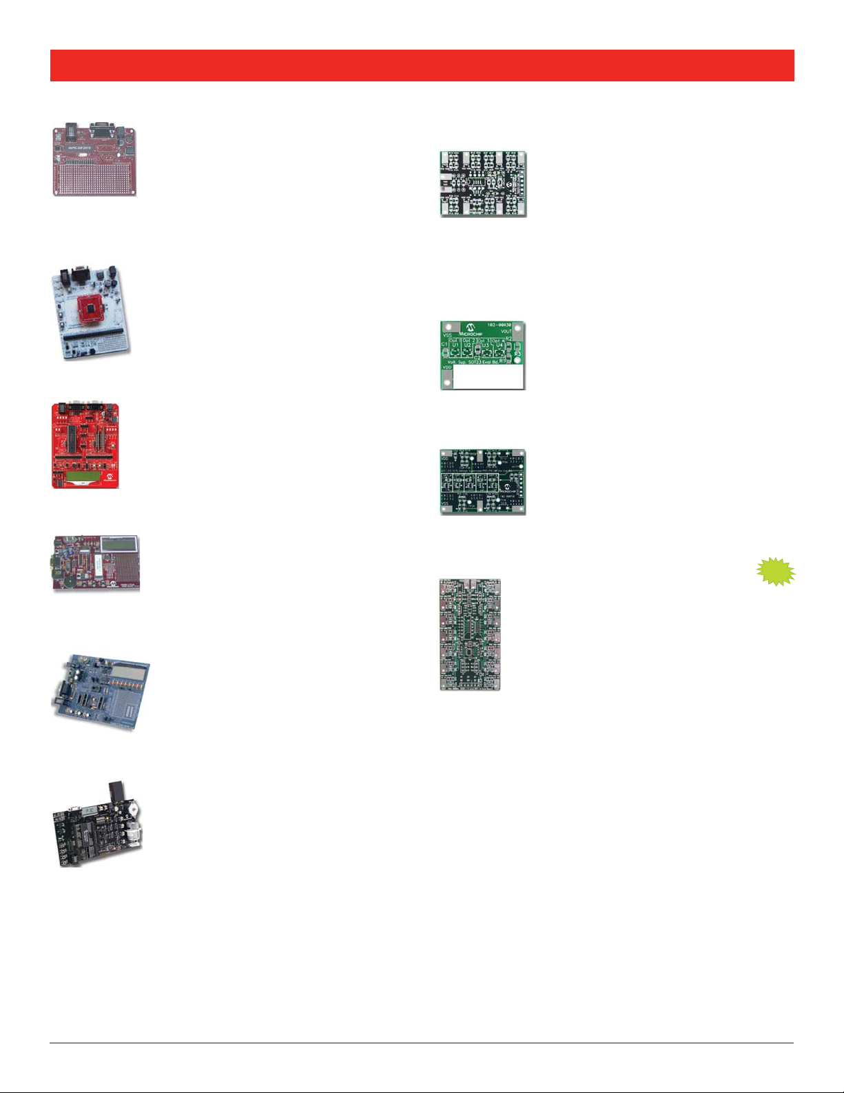
PIC10F2XX Universal Programmer Adapter
Part Number: AC163020
Populates DIP-8 and SOT-23 sockets.
2x3 DFN socket unpopulated.
Part Number: AC163020-2
Populates DIP-8 and 2x3 DFN
sockets. SOT-23 socket unpopulated.
The PIC10F2XX Universal Programmer Adapter provides PIC10F
socket support for the SOT-23, 2x3 DFN and DIP-8 packages.
It provides a simple interface to Microchip’s low-cost family of
programmers including: PICkit™ 1, PICkit™ 2, MPLAB
PICSTART
®
products.
®
ICD 2 and
NEW
Analog Software Tools
MCU Software Tools
MPLAB® IDE
Microchip’s FREE, integrated toolset for the development of PIC
MCU and dsPIC® DSC embedded applications. MPLAB IDE runs as
a 32-bit application on MS Windows, is easy to use and includes a
host of free software components for fast application development
and debugging. MPLAB IDE also serves as a single, unified graphical
user interface for Microchip and third party software/hardware
development tools.
MPLAB® C18 C Compiler
A full-featured ANSI compliant C compiler for the PIC18F family
of 8-bit PIC
application as well as a fully integrated component of MPLAB IDE,
allowing source level debugging with the MPLAB ICE emulator,
the MPLAB ICD 2 debugger and the MPLAB SIM simulator. A fullfeatured 60-day demo of the MPLAB C18 compiler is available at
www.microchip.com.
®
MCUs. MPLAB C18 is a 32-bit Windows console
MPLAB® C30 C Compiler
A fully ANSI-compliant C compiler with standard libraries for the
PIC24 MCU and dsPIC® DSC architectures. Provides efficient
software code generation and extensions that allow for excellent
support of the hardware, such as interrupts and peripherals.
It is fully integrated with the MPLAB IDE for high level, source
debugging. MPLAB C30 comes complete with its own assembler,
linker and librarian, allowing users to write and link mixed mode C
and assembly programs into a single executable file. A full-featured
60-day demo of the MPLAB C30 compiler is available at www.
microchip.com.
®
FilterLab® Active Filter Design Software
The FilterLab Active Filter Software Design
tool simplifies active filter design and
provides full schematic diagrams of the
filter circuit with component values and
displays the frequency response. A free
download is available at the Microchip web
site at:
www.microchip.com
SPICE Software Models
Modeling is the heart of any SPICE simulation system and
Microchip provides a variety of model libraries. This library and
service is an example of Microchip’s focus on analog simulation
and modeling. For more information, visit the Microchip web site
at:
www.microchip.com
Application Maestro™ Software
A stand-alone module tool to configure and incorporate a range of
pre-written firmware modules into PIC® MCU applications. Using a
graphic interface, select one or more modules, then configure the
parameters listed. The Application Maestro software generates
code that can be incorporated into the application project, using
MPLAB® IDE or any compatible development environment.
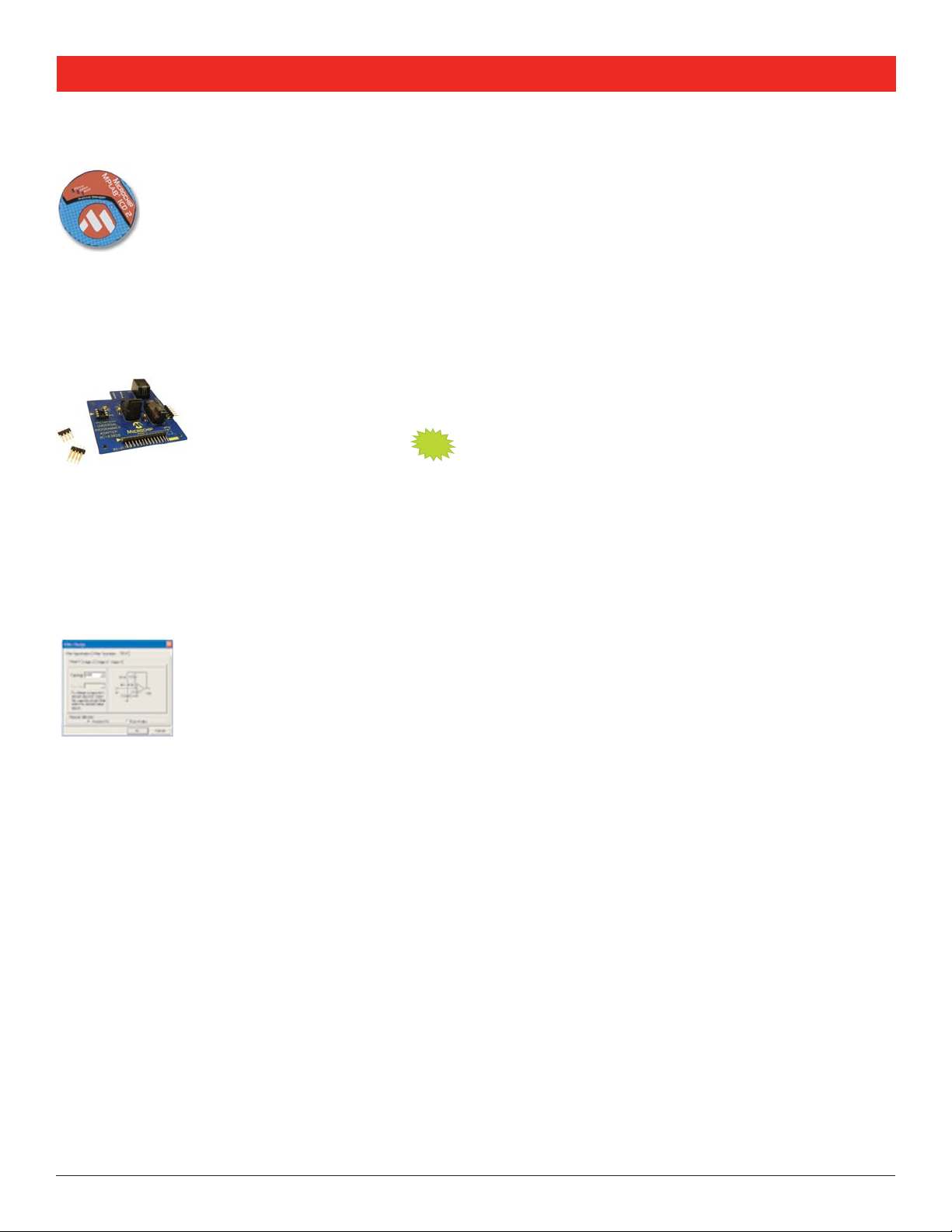
MPLAB® Visual Device Initializer
MPLAB VDI graphically configures the microprocessor and
peripherals, and when complete, generates code usable in
assembly language or C programs. MPLAB VDI does extensive error
checking on assignments and settings, and generates an error
message if there are conflicts on any resources.
12
12
Page 13

Low-Cost Development Tools Guide
dsPIC® DSC Evaluation Software Tools
Digital Filter Design Lite
Part Number: SW300001-LT
This software package provides a subset of the functionality in the
full version of Digital Filter Design. The differences between the
two versions is the number of supported FIR and IIR taps and the
presence of MATLAB support.
dsPIC30F Acoustic Echo Cancellation Library
Part Number: SW300060-EVAL
This library provides a function to eliminate echo generated in
the acoustic path between a speaker and a microphone. Useful
for speech and telephony applications in which a speaker and
a microphone are located in close proximity to each other, and
susceptible to signals propagating from the speaker to the
microphone result in a perceptible and distracting echo effect.
dsPIC30F Line Echo Cancellation Library
Part Number: SW300080-EVAL
The dsPIC30F Line Echo Cancellation Library provides a function
to eliminate echo generated in telephone or digital network
components, such as telephone hybrids. Line echo cancellation
is applicable in telephony applications that involve transmitting
and receiving signals through a telephone hybrid and is especially
suitable for: hands-free cell phone kits, speaker phones, intercoms,
teleconferencing systems and voice-over-internet protocol. This
library is fully compliant with the ITU-T G.168 standard for Digital
Network Echo Cancellers.
dsPIC30F Symmetric Key Embedded Encryption
Library
Part Number: SW300050-EVAL
A reliable security solution for embedded applications built on
the dsPIC30F platform. The Symmetric Key Embedded Encryption
library has the following features: Hash Functions, Symmetric-Key
Encryption/Decryption Functions and Random Number Generator
Functions.
dsPIC30F Asymmetric Key Embedded Encryption
Library
Part Number: SW300055-EVAL
A reliable security solution for embedded applications built on the
dsPIC30F platform. The Asymmetric-Key Embedded Encryption
library implements these functions: Public Key Encryption/
Decryption Functions, Key Agreement Protocol, Signing and
Verification, Hash and Message Digest Functions and Random
Number Generator (RNG).
dsPIC30F Speech Recognition Library
Part Number: SW300010-EVAL
This library is speaker independent US English and provides voice
control of embedded applications that require an alternative user
interface. With a vocabulary of up to 100 words, the Speech
Recognition Library allows users to control their application vocally.
This library is an ideal front end for hands-free products. The library
has very modest memory and processing requirements and is
targeted for the dsPIC30F5011/5013 and dsPIC30F6012/6014
processors.
dsPIC30F Noise Suppression Library
Part Number: SW300040-EVAL
Provides a function to suppress the effect of noise interfering with
a speech signal. This function is useful for microphone-based
applications that have a potential for incoming speech corruption
from ambient noise. It is especially suitable for systems where an
acoustically isolated noise reference is not available.
dsPIC30F V.32 (non-trellis) Soft Modem Library
The Soft Modem libraries are composed of ITU-T compliant
algorithms for V.21, V.22, V.22bis, V.23, V.32 and V.32bis modem
recommendations. Bell standard 103 is also included in these
libraries.
Part Number: SW300003-EVAL
Supports V.21, V.22, V.22bis, V.23, V.32 and V.32bis modem.
Part Number: SW300002 (Free Download)
Supports V.21, V.22 and V.22bis modem.
dsPIC® DSC Speech Encoding/Decoding Library
This library provides toll-quality voice compression and
decompression to help generate speech-based embedded
applications with three available options.
Part Number: SW300026 (Free Download)
Supports ITU-T G.711 (A-law/u-law) companding algorithm.
Part Number: SW300090-EVAL
Supports ITU-T G.726A (ADPCM) companding algorithm.
Part Number: SW300070-EVAL
Supports dsPIC® DSC SPEEX (CELP) companding algorithm.
NEW
NEW
13
Page 14

M
Support
Microchip is committed to supporting its customers
in developing products faster and more efficiently. We
maintain a worldwide network of field applications
engineers and technical support ready to provide product
and system assistance. In addition, the following service
areas are available at www.microchip.com:
■
Support link provides a way to get questions
answered fast: http://support.microchip.com
■
Sample link offers free evaluation samples of any
Microchip device: http://sample.microchip.com
■
Training link offers webinars, registration for local
seminars/workshops and information on annual
MASTERs events held throughout the world:
www.microchip.com/training
Sales Office Listing
Technical Support: http://support.microchip.com
AMERICAS
Atlanta
Tel: 678-957-9614
Boston
Tel: 774-760-0087
Chicago
Tel: 630-285-0071
Cleveland
Tel: 216-447-0464
Dallas
Tel: 972-818-7423
Detroit
Tel: 248-538-2250
Kokomo
Tel: 765-864-8360
Los Angeles
Tel: 949-462-9523
Santa Clara
Tel: 408-961-6444
Toronto
Mississauga, Ontario
Tel: 905-673-0699
ASIA/PACIFIC
Australia - Sydney
Tel: 61-2-9868-6733
China - Beijing
Tel: 86-10-8528-2100
China - Chengdu
Tel: 86-28-8665-5511
China - Fuzhou
Tel: 86-591-8750-3506
China - Hong Kong SAR
Tel: 852-2401-1200
China - Qingdao
Tel: 86-532-8502-7355
China - Shanghai
Tel: 86-21-5407-5533
China - Shenyang
Tel: 86-24-2334-2829
China - Shenzhen
Tel: 86-755-8203-2660
China - Shunde
Tel: 86-757-2839-5507
China - Wuhan
Tel: 86-27-5980-5300
China - Xian
Tel: 86-29-8833-7250
Purchase
microchip
DIRECT
www.microchipdirect.com
tools, including pricing, ordering, inventory and support.
You can buy the products you need on an easily opened
Microchip line of credit.
ASIA/PACIFIC
India - Bangalore
Tel: 91-80-4182-8400
India - New Delhi
Tel: 91-11-4160-8631
India - Pune
Tel: 91-20-2566-1512
Japan - Yokohama
Tel: 81-45-471- 6166
Korea - Gumi
Tel: 82-54-473-4301
Korea - Seoul
Tel: 82-2-554-7200
Malaysia - Penang
Tel: 60-4-646-8870
Philippines - Manila
Tel: 63-2-634-9065
Singapore
Tel: 65-6334-8870
Taiwan - Hsin Chu
Tel: 886-3-572-9526
Taiwan - Kaohsiung
Tel: 886-7-536-4818
Taiwan - Taipei
Tel: 886-2-2500-6610
Thailand - Bangkok
Tel: 66-2-694-1351
microchipDIRECT is a
web-based purchasing
site that gives you
24-hour-a-day access to
all Microchip devices and
EUROPE
Austria - Wels
Tel: 43-7242-2244-39
Denmark - Copenhagen
Tel: 45-4450-2828
France - Paris
Tel: 33-1-69-53-63-20
Germany - Munich
Tel: 49-89-627-144-0
Italy - Milan
Tel: 39-0331-742611
Netherlands - Drunen
Tel: 31-416-690399
Spain - Madrid
Tel: 34-91-708-08-90
UK - Wokingham
Tel: 44-118-921-5869
8-29/06
www.microchip.com/developmenttools
Microchip Technology Inc. • 2355 W. Chandler Blvd. • Chandler, AZ 85224-6199
Microcontrollers • Digital Signal Controllers • Analog • Serial EEPRO
Information subject to change. The Microchip name and logo, the Microchip logo, dsPIC, KEELOQ, MPLAB, PIC, PICmicro, PICSTART and rfPIC are registered trademarks of Microchip Technology
Incorporated in the U.S.A. and other countries. FilterLab, MXDEV, MXLAB and SEEVAL are registered trademarks of Microchip Technology Incorporated in the U.S.A. Application Maestro, dsPICDEM,
ICSP, PICkit, PICDEM and PICtail are trademarks of Microchip Technology Incorporated in the U.S.A. and other countries. SQTP is a service mark of Microchip Technology Incorporated in the U.S.A. All
other trademarks mentioned herein are property of their respective companies. © 2006, Microchip Technology Incorporated. All Rights Reserved. Printed in the U.S.A. 11/06
DS51560D
*DS51560D*
 Loading...