

Page 1
rfPIC
™
Development Kit 1
User’s Guide
© 2003 Microchip Technology Inc. Preliminary DS70093A
Page 2

Note the following details of the code protection feature on Microchip devices:
• Microchip products meet the specification contained in their particular Microchip Data Sheet.
• Microchip believes that its family of products is one of the most secure families of its kind on the market today, when used in the
intended manner and under normal conditions.
• There are dishonest and possibly illegal methods used to breach the code protection feature. All of these methods, to our
knowledge, require using the Microchip products in a manner outside the operating specifications contained in Microchip's Data
Sheets. Most likely, the person doing so is engaged in theft of intellectual property.
• Microchip is willing to work with the customer who is concerned about the integrity of their code.
• Neither Microchip nor any other semiconductor manufacturer can guarantee the security of their code. Code protection does not
mean that we are guaranteeing the product as “unbreakable.”
Code protection is constantly evolving. We at Microchip are committed to continuously improving the code protection features of our
products. Attempts to break microchip’s code protection feature may be a violation of the Digital Millennium Copyright Act. If such
acts allow unauthorized access to your software or other copyrighted work, you may have a right to sue for relief under that Act.
Information contained in this publication regarding device
applications and the like is intended through suggestion only
and may be superseded by updates. It is your responsibility to
ensure that your application meets with your specifications. No
representation or warranty is given and no liability is assumed
by Microchip Technology Incorporated with respect to the
accuracy or use of such information, or infringement of patents
or other intellectual property rights arising from such use or
otherwise. Use of Microchip’s products as critical components in
life support systems is not authorized except with express
written approval by Microchip. No licenses are conveyed,
implicitly or otherwise, under any intellectual property rights.
Trademarks
The Microchip name and logo, the Microchip logo, K
EELOQ,
MPLAB, PIC, PICmicro, PICSTART, PRO MATE and
PowerSmart are registered trademarks of Microchip
Technology Incorporated in the U.S.A. and other countries.
FilterLab, microID, MXDEV, MXLAB, PICMASTER, SEEVAL
and The Embedded Control Solutions Company are registered
trademarks of Microchip Technology Incorporated in the U.S.A.
Accuron, Application Maestro, dsPIC, dsPICDEM,
dsPICDEM.net, ECONOMONITOR, FanSense, FlexROM,
fuzzyLAB, In-Circuit Serial Programming, ICSP, ICEPIC,
microPort, Migratable Memory, MPASM, MPLIB, MPLINK,
MPSIM, PICC, PICkit, PICDEM, PICDEM.net, PowerCal,
PowerInfo, PowerMate, PowerTool, rfLAB, rfPIC, Select Mode,
SmartSensor, SmartShunt, SmartTel and Total Endurance are
trademarks of Microchip Technology Incorporated in the U.S.A.
and other countries.
Serialized Quick Turn Programming (SQTP) is a service mark of
Microchip Technology Incorporated in the U.S.A.
All other trademarks mentioned herein are property of their
respective companies.
© 2003, Microchip Technology Incorporated, Printed in the
U.S.A., All Rights Reserved.
Printed on recycled paper.
Microchip received QS-9000 quality system
certification for its worldwide headquarters,
design and wafer fabrication facilities in
Chandler and Tempe, Arizona in July 1999.
The Company’s quality system processes and
procedures are QS-9000 compliant for its
PICmicro
devices, Serial EEPROMs and microperipheral
products. In addition, Microchip’s quality
system for the design and manufacture of
development systems is ISO 9001 certified.
®
8-bit MCUs, KEELOQ
®
code hopping
DS70093A - page ii Preliminary © 2003 Microchip Technology Inc.
Page 3

rfPIC™ Development Kit 1
User’s Guide
Table of Contents
Preface ........................................................................................................................... 1
Chapter 1. Getting Started
1.1 Introduction ..................................................................................................... 5
1.2 Highlights ........................................................................................................ 5
1.3 rfPIC Development Kit 1 Contents ................................................................. 5
1.4 Getting Started with the rfPIC Development Kit 1 .......................................... 6
1.4.1 Preparing the Receiver Module for Operation ................................. 6
1.4.2 Preparing the Transmitter Module for Operation ............................. 7
1.4.3 Demonstration Operation ................................................................ 7
1.5 Demonstration Programs and HEX Files ....................................................... 7
Chapter 2. Demonstration Programs
2.1 Introduction ..................................................................................................... 9
2.2 Highlights......................................................................................................... 9
2.3 About the Demonstration Programs ............................................................... 9
2.4 XMIT_DEMO ................................................................................................ 10
2.5 RCVR_DEMO .............................................................................................. 10
2.6 RCVR_ANALOG_DISPLAY ......................................................................... 10
2.7 XMIT_TEST................................................................................................... 11
2.7.1 Peak Power Measurement ............................................................ 11
2.7.2 Data Modulation and Bandwidth Measurement ............................. 11
2.8 Presentation Pal ........................................................................................... 11
2.8.1 USB Firmware - pres_pal.hex ....................................................... 11
2.8.2 Transmitter Firmware - prespal_xmit.hex ...................................... 12
2.9 Programming Templates .............................................................................. 12
Chapter 3. rfRXD0420 Receiver Module
3.1 Introduction ................................................................................................... 13
3.2 Highlights ...................................................................................................... 13
3.3 rfRXD0420 Description ................................................................................. 14
3.4 rfRXD0420 Schematic .................................................................................. 15
3.5 PCB Layout .................................................................................................. 16
3.6 Gerber Files .................................................................................................. 16
3.7 rfRXD0420 Receiver Module Bill-of-Materials .............................................. 17
3.8 Third Party Component Suppliers ................................................................. 18
© 2003 Microchip Technology Inc. Preliminary DS70093A-page iii
Page 4

rfPIC™ Development Kit 1 User’s Guide
Chapter 4. rfPIC12F675 Transmitter Module
4.1 Introduction ................................................................................................... 19
4.2 Highlights ...................................................................................................... 19
4.3 rfPIC12F675 Description .............................................................................. 19
4.3.1 Power Requirements ..................................................................... 20
4.3.2 Programming the rfPIC12F675 ...................................................... 20
4.3.3 Optional 8-pin Socket U2 ............................................................... 20
4.4 rfPIC12F675 Schematic ............................................................................... 22
4.5 PCB Layout .................................................................................................. 23
4.6 Gerber Files .................................................................................................. 24
4.7 rfPIC12F675 Transmitter Module Bill-of-Materials ....................................... 25
4.8 Third Party Component Suppliers ................................................................ 26
Chapter 5. Troubleshooting
5.1 Introduction ................................................................................................... 27
5.2 Frequently Asked Questions ........................................................................ 27
5.2.1 Devices on the PICkit™ Starter Kit Have No Power? ................... 27
5.2.2 Programmer Not Found ................................................................. 28
5.2.3 Insert Device .................................................................................. 28
5.2.4 Checksum Verify Failed ................................................................. 29
Worldwide Sales and Service .....................................................................................32
DS70093A-page iv Preliminary © 2003 Microchip Technology Inc.
Page 5

INTRODUCTION
HIGHLIGHTS
rfPIC™ Development Kit 1
User’s Guide
Preface
This chapter contains general information about this user’s guide and customer support
that will be useful prior to using the rfPIC™ Development Kit 1.
Items discussed in this Preface are:
• About this Guide
• Warranty Registration
• Recommended Reading
• Troubleshooting
• Microchip On-Line Support
• Customer Change Notification Service
• Customer Support
ABOUT THIS GUIDE
This document describes how to use the rfPIC Development Kit 1. The manual layout
is as follows:
• Chapter 1: Getting Started – Step by step instructions on how to use your rfPIC
Development Kit 1.
• Chapter 2: Demonstration Programs – Programs to familiarize the developer with
the rfPIC and rfRXD products and provide a starting point for future development.
• Chapter 3: rfRXD0420 Receiver Module – Description, schematics, PCB layout,
and Bill-of-Materials.
• Chapter 4: rfPIC12F675 Transmitter Module – Description, schematics, PCB
layout, and Bill-of-Materials.
• Chapter 5: Troubleshooting – This chapter describes common problems
associated with using the rfPIC Development Kit 1 and steps on how to resolve
them.
• Worldwide Sales and Service – A list of Microchip sales and service locations
and telephone numbers worldwide.
© 2003 Microchip Technology Inc. Preliminary DS70093A-page 1
Page 6
rfPIC™ Development Kit 1 User’s Guide
Conventions Used in This Guide
This manual uses the following documentation conventions:
TABLE 1: DOCUMENTATION CONVENTIONS
Description Represents Examples
Code (Courier font):
Plain characters Sample code
Filenames and paths
Angle brackets: < > Variables <label>, <exp>
Square brackets [ ] Optional arguments MPASMWIN [main.asm]
Curly brackets and pipe
character: { | }
Lower case characters
in quotes
Ellipses... Used to imply (but not show)
0xnnn A hexadecimal number where n is a
Italic characters A variable argument; it can be either a
Interface (Arial font):
Underlined, italic text
with right arrow
Bold characters A window or dialog button to click OK, Cancel
Characters in angle
brackets < >
Documents (Arial font):
Italic characters Referenced books
Choice of mutually exclusive
arguments; An OR selection
Type of data
additional text that is not relevant to
the example
hexadecimal digit
type of data (in lower case characters)
or a specific example (in upper case
characters).
A menu selection from the menu bar File > Save
A key on the keyboard <Tab>, <Ctrl-C>
#define START
c:\autoexec.bat
errorlevel {0|1}
"filename"
list
"list_option...,
[
"list_option"]
0xFFFF, 0x007A
char isascii (char,
ch);
®
MPLAB
IDE User’s Guide
Documentation Updates
All documentation becomes dated, and this user’s guide is no exception. Since the
rfPIC™ Development Kit 1 User’s Guide and other Microchip tools are constantly
evolving to meet customer needs, some rfPIC Development Kit 1 actual dialogs and/or
tool descriptions may differ from those in this document. Please refer to our web site to
obtain the latest documentation available.
Documentation Numbering Conventions
Documents are numbered with a “DS” number. The number is located on the bottom of
each page, in front of the page number. The numbering convention for the DS Number
is: DSXXXXXA,
where:
XXXXX = The document number.
A = The revision level of the document.
DS70093A-page 2 Preliminary © 2003 Microchip Technology Inc.
Page 7

WARRANTY REGISTRATION
Please complete the enclosed Warranty Registration Card and mail it promptly.
Sending in your Warranty Registration Card entitles you to receive new product
updates. Interim software releases are available at the Microchip web site.
RECOMMENDED READING
Other useful documents are listed below:
rfPIC12F675K/675F/675H Data Sheet (DS70091)
Consult this document for information regarding the rfPIC12F675 20-pin FLASH-based
8-bit CMOS microcontroller with UHF ASK/FSK transmitter device specifications.
rfRXD0420/0920 Data Sheet (DS70090)
Consult this document for information regarding the rfRXD0420 UHF ASK/FSK/FM
receiver device specifications.
PIC12F629/675 Data Sheet (DS41190)
Consult this document for information regarding the PIC12F629/675 8-pin
FLASH-based 8-bit CMOS microcontroller device specifications.
PIC16F630/676 Data Sheet (DS40039)
Consult this document for information regarding the PIC16F630/676 14-pin
FLASH-based 8-bit CMOS microcontroller device specifications.
PICkit™ 1 FLASH Starter Kit User’s Guide (DS40051)
Consult this document for information regarding the PICkit 1 FLASH Starter Kit.
MPLAB
Consult this document for more information pertaining to the installation and features
of the MPLAB Integrated Development Environment (IDE) Software.
To obtain these documents, contact the nearest Microchip sales location (see back
page). These documents are also available on the Microchip web site at:
www.microchip.com.
Application Notes
There are several application notes for the rfPIC products available on the rfPIC™
Development Kit CD-ROM.
Microsoft
This manual assumes that users are familiar with the Microsoft Windows operating
system. Many excellent references exist for this software program, and should be
consulted for general operation of Windows.
®
IDE User’s Guide (DS51025)
®
Windows® Manuals
Preface
TROUBLESHOOTING
See Chapter 5. "Troubleshooting" for information on common problems.
THE MICROCHIP INTERNET WEB SITE
Microchip provides easy access to our documentation and on-line support through our
World Wide Web Site at www.microchip.com. You can download files from the web site
or from our FTP site at ftp://ftp.microchip.com
© 2003 Microchip Technology Inc. Preliminary DS70093A-page 3
Page 8

rfPIC™ Development Kit 1 User’s Guide
CUSTOMER SUPPORT
Users of Microchip products can receive assistance through several channels:
• Distributor or Representative
• Local Sales Office
• Field Application Engineer (FAE)
• Corporate Applications Engineer (CAE)
• Hot line
Customers should call their distributor, representative or field application engineer
(FAE) for support. Local sales offices are also available to help customers. See the
back cover for a listing of sales offices and locations.
Corporate Applications Engineers (CAEs) may be contacted at (480) 792-7627.
In addition, there is a Systems Information and Upgrade Line. This line provides system
users a listing of the latest versions of all of Microchip's development systems software
products. Plus, this line provides information on how customers can receive any currently available upgrade kits.
The Hot Line Numbers are:
• 1-800-755-2345 for U.S. and most of Canada, and
• 1-480-792-7302 for the rest of the world
CUSTOMER CHANGE NOTIFICATION SERVICE
Microchip started the customer notification service to help customers stay current on
Microchip products with the least amount of effort. Once you subscribe, you will receive
E-mail notification whenever we change, update, revise or have errata related to your
specified product family or development tool of interest.
Go to the Microchip web site (www.microchip.com) and click on Customer Change
Notification. Follow the instructions to register.
The Development Systems product group categories are:
• Compilers
• Emulators
• In-Circuit Debuggers
• MPLAB
• Programmers
Here is a description of these categories:
Compilers – The latest information on Microchip C compilers and other language
tools. These include the MPLAB
MPASM
and MPLIB
Emulators – The latest information on Microchip in-circuit emulators. This includes the
MPLAB
In-Circuit Debuggers – The latest information on Microchip in-circuit debuggers.
These include the MPLAB
MPLAB – The latest information on Microchip MPLAB
Development Environment for development systems tools. This list is focused on the
MPLAB
and debugging features.
Programmers – The latest information on Microchip device programmers. These
include the PRO MATE
programmer.
®
IDE
®
™
and MPLAB ASM30 assemblers; MPLINK™ and MPLAB® LINK30 linkers;
™
and MPLAB® LIB30 librarians.
®
ICE 2000.
®
®
IDE, MPASM™ simulator, MPLAB IDE Project Manager and general editing
®
II device programmer and PICSTART® Plus development
C17, MPLAB® C18 and MPLAB® C30 C Compilers;
ICD and MPLAB ICD 2.
®
IDE, the Windows® Integrated
DS70093A-page 4 Preliminary © 2003 Microchip Technology Inc.
Page 9

1.1 INTRODUCTION
rfPIC™ Development Kit 1
User’s Guide
Chapter 1. Getting Started
The rfPIC Development Kit 1 is a demonstration and development kit for the
rfPIC12F675K and rfPIC12F675F PICmicro
transmitters and rfRXD0420 UHF ASK/FSK/FM receiver. The transmitter and receiver
modules are designed to plug into the PICkit™ 1 FLASH Starter Kit expansion header
J3 for a low-cost development system.
1.2 HIGHLIGHTS
This chapter discusses:
• rfPIC Development Kit 1 Contents
• Getting Started with the rfPIC Development Kit 1
• Demonstration Programs and HEX Files
1.3 rfPIC DEVELOPMENT KIT 1 CONTENTS
The rfPIC Development Kit 1 contains the following items:
1. rfPIC12F675K 315 MHz Transmitter Module
2. rfPIC12F675F 433.92 MHz Transmitter Module
3. rfRXD0420 315 MHz Receiver Module
4. rfRXD0420 433.92 MHz Receiver Module
5. Programmed PIC16F676
6. rfPIC™ Development Kit 1 Quick Start Guide
7. rfPIC™ Development Kit 1 CD-ROM
8. PICkit 1 FLASH Starter Kit Printed Circuit Board
9. USB Cable
10. PICkit™
11. MPLAB
1 FLASH Starter Kit CD-ROM
®
IDE CD-ROM
®
microcontrollers with UHF ASK/FSK
© 2003 Microchip Technology Inc. Preliminary DS70093A-page 5
Page 10
rfPIC™ Development Kit 1 User’s Guide
1.4 GETTING STARTED WITH THE rfPIC DEVELOPMENT KIT 1
The transmitter modules come pre-programmed with a transmitter demonstration. The
enclosed PIC16F676 is programmed with a receiver demonstration program. Together
they demonstrate an on-off command and control application.
The PICkit
platform for the transmitter and receiver modules.
To see your rfPIC Development Kit 1 in action, perform the following steps:
1 FLASH Starter Kit serves as a low-cost development and demonstration
1.4.1
Preparing the Receiver Module for Operation
Step 1:
Familiarize yourself with the PICkit 1 FLASH Starter Kit operation by reading the
PICkit™ 1 FLASH Starter Kit User’s Guide (DS40051) and performing some of the
tutorials. Familiarity with the PICkit Starter Kit will be assumed throughout this user’s
guide.
Step 2:
Remove power from the PICkit Starter Kit by disconnecting the USB cable.
Step 3:
Remove the PIC12F675 from the PICkit Starter Kit evaluation socket.
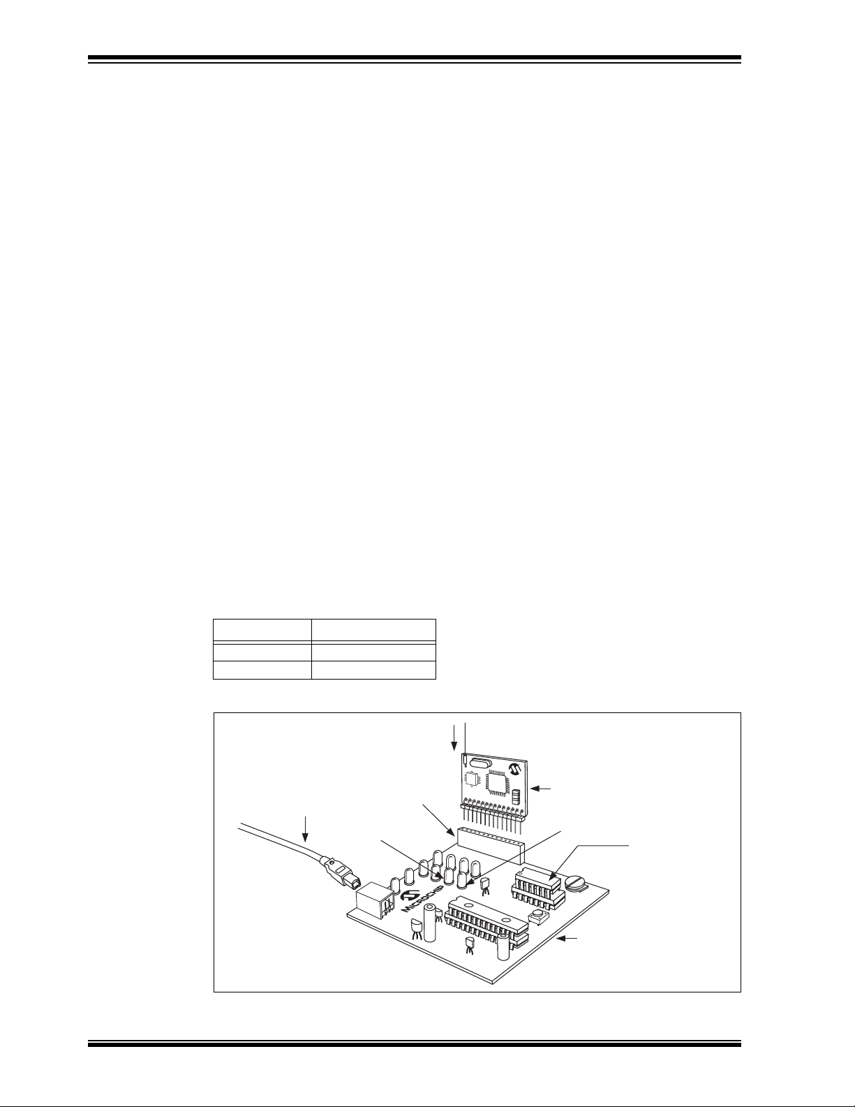
Step 4:
Insert the PIC16F676 into the PICkit Starter Kit evaluation socket. See Figure 1-1.
Step 5:
Insert a receiver module (315 or 433.92 MHz) into the PICkit Starter Kit expansion
header J3. Make certain that the receiver module is oriented correctly. See Figure 1-1.
Step 6:
Insert the wire antenna into the antenna connector on the receiver module. See
Figure 1-1. The wire antenna length is determined by the receive frequency. For the
corresponding frequency, insert the following wire antenna:
Frequency Antenna Length
315 MHz 9-3/8”
433.92 MHz 6-3/4”
FIGURE 1-1: rfPIC RECEIVER DEMONSTRATION
Wire Antenna
Expansion
USB Cable
LED D1
DS70093A-page 6 Preliminary © 2003 Microchip Technology Inc.
Header (J3)
rfRXD Receiver Module
LED D0
Insert PIC16F676
PICkit™ FLASH Starter Kit
Page 11
Getting Started
Step 7:
Power-on the PICkit Starter Kit by connecting the USB cable to a personal computer or
externally powered USB hub.
Note: There is no interaction between the receiver demonstration program in the
PIC16F676 and the personal computer.
The receiver module is ready for operation.
1.4.2
Preparing the Transmitter Module for Operation
Step 1:
Select the transmitter module that matches the receive frequency of the receiver
module installed in the PICkit Starter Kit.
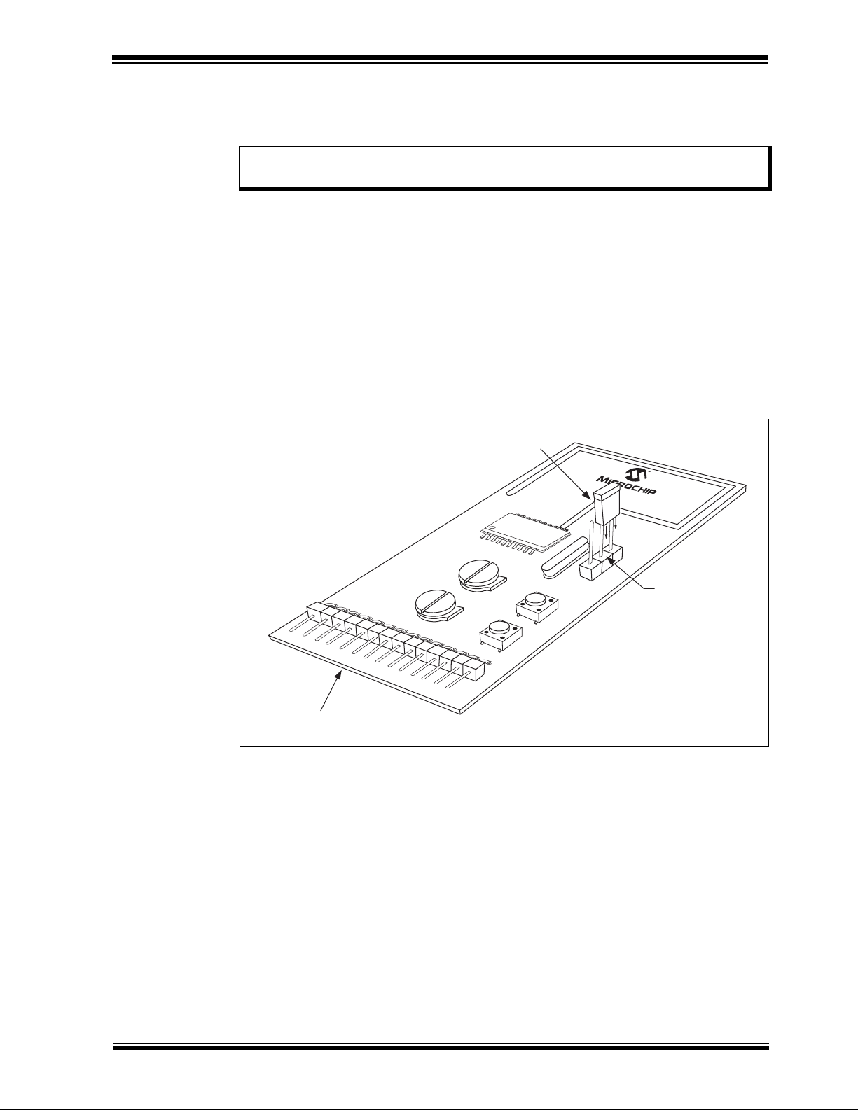
Step 2:
Power-on the transmitter module by positioning the shunt jumper to the batt position on
P1 (between center pin and batt pin). See Figure 1-2.
The transmitter module is ready for operation.
FIGURE 1-2: rfPIC TRANSMITTER DEMONSTRATION
Jumper
rfPIC12F675
P1
PICkit™ Batt
GP0 GP1
Pwr Sel P1
GP3 GP4
rfPIC™ Transmitter Module
1.4.3
Demonstration Operation
The demonstration program is a simple on-off command and control application. Pressing push button GP3 (SW2) on the transmitter module lights LED D0 on the PICkit
Starter Kit. Pressing push button GP4 (SW1) lights LED D1.
1.5 DEMONSTRATION PROGRAMS AND HEX FILES
Additional demonstration programs are provided on the rfPIC™ Development Kit 1
CD-ROM. Chapter 2 provides an explanation of each program. HEX files and program
source code are provided. The HEX files can be programmed into the rfPIC transmitter
and receiver modules using the PICkit 1 FLASH Starter kit. The source code can be
modified and compiled using the MPLAB
software and the resulting HEX files programmed in the same manner.
®
Integrated Development Environment (IDE)
© 2003 Microchip Technology Inc. Preliminary DS70093A-page 7
Page 12

rfPIC™ Development Kit 1 User’s Guide
NOTES:
DS70093A-page 8 Preliminary © 2003 Microchip Technology Inc.
Page 13

Chapter 2. Demonstration Programs
2.1 INTRODUCTION
The demonstration programs provided on the rfPIC Development Kit 1 CD-ROM give
examples of wireless applications. The programs familiarize the developer with the
rfPIC and rfRXD products and provide a starting point for future development.
2.2 HIGHLIGHTS
The following demonstration programs are discussed in this chapter:
xmit_demo
rcvr_demo
rcvr_analog_display
xmit_test
tuning
Presentation Pal
presentation helper
Programming Templates
provided to assist the programmer in getting started with new projects
rfPIC™ Development Kit 1
User’s Guide
– a transmitter command, control and analog application demonstration
– a receiver command and control application demonstration
– a receiver analog demonstration
– a transmitter test program used for pre-compliance testing and antenna
– programs to turn your rfPIC Development Kit 1 into a wireless
– a set of thoroughly commented programming templates
2.3 ABOUT THE DEMONSTRATION PROGRAMS
The demonstration programs are provided in *.hex format so that the user can
immediately program the device and begin testing. They are also available in *.asm
format so that the user can study the program source code and comments and as a
starting point for future development.
The transmitter module demonstration programs are programmed into the transmitter
module by following the steps in Chapter 4 of this User’s Guide. The receiver module
demonstration programs are programmed into the PIC16F676 by following the steps
outlined in the PICkit™ 1 FLASH Starter Kit User’s Guide.
© 2003 Microchip Technology Inc. Preliminary DS70093A-page 9
Page 14

rfPIC™ Development Kit 1 User’s Guide
2.4 XMIT_DEMO
XMIT-DEMO is the default program that is preprogrammed into the transmitter module. It
is used with the receiver module programs rcvr_demo and rcvr_analog_display.
This program demonstrates simple command, control and analog application demonstrations. To see each demonstration, the user must load the appropriate receiver code
examples:
rcvr_demo.asm and rcvr_demo.hex
When a push button on the transmitter module is depressed, the corresponding LED is
lit on the PICkit
lights LED D0 on the PICkit 1 Starter Kit. Pressing push button GP4 lights LED D1.
rcvr_analog_display.asm and rcvr_analog_display.hex
Pressing transmitter module push button GP3 lights LEDs D0-D7 on the PICkit
Kit with the upper 8-bit value read from the transmitter module 10-bit A/D channel 0
connected to potentiometer GP0. Pressing push button GP4 lights LEDs D0-D7 with
the upper 8-bit value read from A/D channel 1 connected to potentiometer GP1.
The protocol is a simplified K
products. This receive code was adapted from Microchip Technology application note
AN740.
The 10-bit analog value is placed into the 16-bit counter field of the simplified K
protocol.
1 FLASH Starter Kit. Pressing the transmitter module push button GP3
EELOQ
®
protocol compatible with the HCS101 fixed code
Starter
EELOQ
2.5 RCVR_DEMO
This program demonstrates a simple command and control application. When a push
button on the transmitter module is depressed, the corresponding LED is lit on the
PICkit 1 FLASH Starter Kit.
Pressing transmitter module push button GP3 lights LED D0 on the PICkit 1. Pressing
push button GP4 lights LED D1.
The protocol is a simplified K
products. This receive code was adapted from Microchip Technology application note
AN740.
2.6 RCVR_ANALOG_DISPLAY
This program demonstrates a simple analog display application. When a push button
on the transmitter module is depressed, the corresponding LED is lit on the PICkit
FLASH Starter Kit.
Pressing transmitter module push button GP3 lights LEDs D0-D7 on the PICkit Starter
Kit with the upper 8-bit value read from the transmitter module 10-bit A/D channel 0
connected to potentiometer GP0. Pressing push button GP4 lights LEDs D0-D7 with
the upper 8-bit value read from A/D channel 1 connected to potentiometer GP1.
The protocol is a simplified K
products. This receive code was adapted from Microchip Technology application note
AN740.
The 10-bit analog value is placed into the 16-bit counter field of the simplified K
protocol.
EELOQ protocol compatible with the HCS101 fixed code
1
EELOQ protocol compatible with the HCS101 fixed code
EELOQ
DS70093A-page 10 Preliminary © 2003 Microchip Technology Inc.
Page 15

2.7 XMIT_TEST
This program implements two tests that can be used to verify RF performance of the rfPIC
Development Kit transmitter modules using a spectrum analyzer and calibrated antenna.
The tests start when the indicated push button is pressed and stop when the push button
is released. The processor sleeps between tests to conserve battery power.
Demonstration Programs
2.7.1
Press push button GP3 (SW2). This test generates a constant unmodulated output for
measuring peak output power. This test can be used for regulatory pre-compliance
testing and antenna tuning.
2.7.2
Set potentiometer GP0 in one of four quarter positions to choose maximum, high,
medium, or low speed signal rate. Then press GP4 (SW1) and fine adjust potentiometer GP1 for the desired signal rate. The signal is a square wave and does not exactly
match the PWM or Manchester spectrums, but is quite useful to determine system
performance. Table 2-1 demonstrates the approximate signal rates. Note that
increasing the analog voltage decreases the signal rate and that the NRZ bps is double
the modulation frequency.
TABLE 2-1: APPROXIMATE SIGNAL RATES
Peak Power Measurement
Data Modulation and Bandwidth Measurement
GP0
0-25% 52.6-3.64 kbps 19-274 µsec
25-50% 3.64-1.88 kbps 275-530 µsec
50-75% 1.88-1.27 kbps 531-786 µsec
75-100% 1.27-0.96 kbps 787-1042 µsec
2.8 PRESENTATION PAL
NRZ bps
(0-100% GP1)
NRZ Pulse Width
(0-100% GP1)
The Presentation Pal application turns your rfPIC Development Kit 1 into a wireless
slide show presentation helper. By pressing the push-buttons on the transmitter
module, the commands are converted to page-up and page-down keyboard
commands for a personal computer. There are two programs required for this
application.
2.8.1
Step 1:
The first step in converting your rfPIC Development Kit 1 is to program a blank
PIC16C745 8-bit CMOS microcontroller with USB (not included with the rfPIC
Development Kit) with pres_pal.hex. The PIC16C745 is a one time programmable
(OTP) microcontroller and can be programmed on a PICSTART
II programmer.
Step 2:
Remove the PICkit 1 FLASH Kit programmed PIC16C745 from socket U1. Insert the
PIC16C745 programmed with pres_pal.hex into socket U1.
USB Firmware - pres_pal.hex
®
Plus or PRO MATE®
© 2003 Microchip Technology Inc. Preliminary DS70093A-page 11
Page 16

rfPIC™ Development Kit 1 User’s Guide
Step 3:
Remove the PIC12F675 microcontroller from the evaluation socket. Insert a wire
jumper between pins 9 and 13.
Step 4:
When the PICkit Starter Kit is plugged into the personal computer USB jack, the
program will enumerate as a keyboard.
Button presses on the transmitter module are interpreted as page-down, page-up and
Alt-Tab keyboard commands. Page-down advances the slide. Page-up goes
backwards in the slide presentation. When both buttons are pressed, Alt-Tab alternates
between active programs.
2.8.2
This program sends button press commands to the receiver. The button press
commands are interpreted and sent to the personal computer as page-down and
page-up commands to advance or retreat the slide presentation running on the
computer.
This program is a slightly modified version of xmit_demo.asm. This program sends a
different count value for each push button press. This allows the receiver to delay
advancing the slide if the push button is pressed for an extended period of time. The
receiver will delay advancing a few seconds if the push button is continuously pressed.
This is similar to the key press auto-repeat feature of many personal computer
keyboards.
Transmitter Firmware - prespal_xmit.hex
2.9 PROGRAMMING TEMPLATES
Thoroughly commented templates are provided to assist the programmer in getting
started with new projects. Two templates are provided:
PIC12F629-675 Assembly Language Programming Template.asm
Use this template to program the PIC12F629 or PIC12F675 8-pin FLASH PICmicro
MCU or the rfPIC12F675K/675F/675H PICmicro MCU with UHF ASK/FSK transmitter
devices.
PIC16F630-676 Assembly Language Programming Template.asm
Use this template to program the PIC16F630 or PIC16F676 14-pin FLASH PICmicro
microcontroller.
®
DS70093A-page 12 Preliminary © 2003 Microchip Technology Inc.
Page 17

Chapter 3. rfRXD0420 Receiver Module
3.1 INTRODUCTION
The rfRXD0420 Receiver Module (see Figure 3-1) is a low cost, high performance UHF
short-range radio ASK receiver design using the Microchip Technology rfRXD0420.
The module design is suitable for:
• Wireless remote command and control
• Remote Keyless Entry (RKE)
• Security systems
• Low power telemetry applications
The specifics of the receiver module design are:
• Single channel, fixed frequency at 315 MHz and 433.92 MHz
• ASK modulation
• Signal rate: 4800 baud
Schematics, PCB layout and Bill-of-Materials (BOM) are provided in the following
sections. Gerber files are available on the rfPIC™ Development Kit 1 CD-ROM.
The receiver module can be purchased separately or in packs of 5. See Table 3-1
rfPIC™ Development Kit 1
User’s Guide
TABLE 3-1: RECEIVER MODULE ORDERING INFORMATION
3.2 HIGHLIGHTS
This chapter discusses:
• rfRXD0420 Receiver Module Description
• rfRXD0420 Receiver Module Schematic
• PCB Layout
• Gerber Files
• Bill-of-Materials
• Third Party Component Suppliers
Order Number
Frequecy Single 5 Pack
315 MHz AC164104 AC164106
433.92 MHz AC164103 AC164105
© 2003 Microchip Technology Inc. Preliminary DS70093A-page 13
Page 18

rfPIC™ Development Kit 1 User’s Guide
3.3 rfRXD0420 DESCRIPTION
The rfRXD0420 is a stand-alone receiver module that can be used in a variety of ways.
• It can be plugged into the PICkit 1 FLASH Starter Kit expansion header J3 for
demonstration and development.
• The receiver module can be installed in any project for proof-of-concept, demonstration, or
development purposes. Once project proof-of-concept and demonstration have been
proven, the designer can use the available Gerber files or complete a design of their own.
A detailed description of the rfRXD0420 UHF ASK/FSK/FM receiver is provided in the
data sheet, DS70090.
A detailed description of the rfRXD0420 receiver module design is provided in application
note, AN860.
FIGURE 3-1: rfRXD0420 RECEIVER MODULE
Table 3-2 lists the pinout for the rfRXD0420 receiver Module.
TABLE 3-2: rfRXD0420 RECEIVER MODULE PINOUT
Pin Description
1-10 No Connection
11 Receive Data In
12 No Connection
13 Power: 2.5-5.5 VDC
14 Ground
ANT Antenna Connection
The antenna connection is a 0.055 inch pin receptical. A simple small diameter wire
(AWG 24) antenna can be constructed and inserted into the receptical. The length of
the antenna wire depends on the frequency.
λ (meters) = c / f (Hertz)
where
8
c = 3x10
= speed of light (meters per second)
f = receive frequency (Hertz)
λ = wavelength (meters)
The length of the antenna wire in inches can be found for a given frequency using the
following formula:
wire antenna length (inches) = 2952.8 / f (MHz)
Alternatively, the pin receptical can be removed and an alternate antenna connection
can be made. For example, a coaxial wire can be connected to the antenna pad on the
front side of the PCB and ground pad on the back side of the PCB.
DS70093A-page 14 Preliminary © 2003 Microchip Technology Inc.
Page 19

3.4 rfRXD0420 SCHEMATIC
Figure 3-2 is a detailed schematic of the rfRXD0420 module.
FIGURE 3-2: rfRXD0420 RECEIVER MODULE
rfRXD0420 Receiver Module
C13
1000 pF
RC1
C9
33000 pF
Ω
R6
1 k
C12
1000 pF
C4
330 pF
C2
47000 pF
+V
R1
100 kΩ
C1
1800 pF
*
3.0 pF
*
C3
330 pF
+V
+V
C5
330 pF
C8
330 pF
1718192021222324
NC
NC
C7
DD
R2 390Ω
NC
NC
DD
V
FBC2
V
IN_DEM
OUT_IFA
OUT_OA
OAN
OAP
RSSI
U1
VSS
OUTP
rfRXD0420
OUTN
VSSRO
VDDENRXLFVSSIN_LNA
25262728293031
FBC1
IN_IFA
+V
9
10111213141516
VSS
OUT_MIX2
DD
V
32
F2
10.7 MHz
DD
V
IF1N
IF1P
V
SS
IN_MIX1
OUT_LNA
GAIN_LNA
12345678
V
SS
C14
330 pF
C16
+V
330 pF
470ΩR5470Ω
R4
C15
+V
muRata P/N
Bandwidth
Ceramic IF Filter F2
Freq.
C17
C15 L3 C17
LNA Tuned Circuit
L3
Freq.
C18
330 pF
SFECV10M7GA00
230 kHz
10.7 MHz
7.0 pF 22 nH 6.0 pF
3.0 pF 15 nH 6.0 pF
315 MHz
433.92 MHz
L1 L2 C7
82 nH 82 nH
33 nH 27 nH
39 nH 39 nH
*
*
C6
3.0 pF
EPCOS SAW Filter F1
Freq.
315 MHz
433.92 MHz
433.92 MHz
1. * = Not Placed
2. EPCOS B3551 (315 MHz) SAW filter is not pin
B3751
B3550
B3750
Part No.
NOTES:
5
6
F1SAW Filter
Output
3478
Output GND
Case-GND
Input GND
Input
1
2
compatable with the above SAW filters.
L1 L2
C6
ANT
R3
1000 pF
0Ω
Crystal X1
10 kΩ
X1
016999
016985
Crystek P/N
X1 Freq.
20.35625 MHz
26.45125 MHz
Freq.
315 MHz
433.92 MHz
C11
C10
capacitor) with 0 ohm resistor
NOTE: Populate C10 (optional C Trim
RA5
1
P1
To PICkit™ J3
RA4
RA3
432
RC5
RC4
RC3
RA0
RA1
98765
RA2
RC0
RC1
L4
RC2
+V
C19
330 pF
FB
1413121110
© 2003 Microchip Technology Inc. Preliminary DS70093A-page 15
Page 20

rfPIC™ Development Kit 1 User’s Guide
3.5 PCB LAYOUT
The following figures illustrate the various layers of the rfRXD0420 receiver module
printed circuit board.
FIGURE 3-3: rfRXD0420 TOP SILK-SCREEN
FIGURE 3-4: rfRXD0420 TOP COPPER
FIGURE 3-5: rfRXD0420 BOTTOM COPPER
3.6 GERBER FILES
Gerber Files for the rfRXD0420 are available on the rfPIC Development Kit 1 CD-ROM.
DS70093A-page 16 Preliminary © 2003 Microchip Technology Inc.
Page 21

rfRXD0420 Receiver Module
y
g
r
r
g
y
p
g
y
p
g
y
p
g
y
p
g
y
p
g
y
3.7 rfRXD0420 RECEIVER MODULE BILL-OF-MATERIALS
PCC1769TR-ND
PCC1771TR-ND
TKS3715TR-ND
TKS3713TR-ND
TKS3722TR-ND
TKS3718TR-ND
240-1143-2-ND
rfRXD0420 Receiver Module Bill-of-Materials
Value Description Order From Part Numbe
330 pF, X7R, 0603 Capacitor, Ceramic Chip Digi-Key PCC331ACVTR-ND
i-Ke
Capacitor, Ceramic Chip Digi-Key
47000 pF, X7R, 0603
i-Ke
Di
i-Ke
Di
i-Ke
Di
i-Ke
Di
i-Ke
Di
nato
Desi
2 C6, C7 Not Placed
Quantit
© 2003 Microchip Technology Inc. Preliminary DS70093A-page 17
C3, C4, C5, C8, C14, C16, C18, C19
1 C15 - 433.92 MHz 3 pF, NP0, 0603 Capacitor, Ceramic Chip Digi-Key PCC030CVTR-ND
1 C17 6 pF, NP0, 0603 Capacitor, Ceramic Chip Digi-Key PCC060CVTR-ND
1 C15 - 315 MHz 7 pF, NP0, 0603 Capacitor, Ceramic Chip Digi-Key PCC070CVTR-ND
8
3 C11, C12, C13 1000 pF, X7R, 0603 Capacitor, Ceramic Chip Digi-Key PCC1772TR-ND
1 C1 1800 pF, X7R, 0603 Capacitor, Ceramic Chip Digi-Key PCC1775TR-ND
1 C9 33000 pF, X7R, 0603 Capacitor, Ceramic Chip Di
1C2
1 C10 0 ohm, 0603 Resistor, Chip, Thick Film Digi-Key P0.0GTR-ND
1 R2 390 ohm, 0603 Resistor, Chip, Thick Film Digi-Key P390GTR-ND
2 R4, R5 470 ohm, 0603 Resistor, Chip, Thick Film Digi-Key P470GTR-ND
1 R6 1K ohm Resistor, Chip, Thick Film Digi-Key P1.0KGTR-ND
1 R3 10K ohm, 0603 Resistor, Chip, Thick Film Digi-Key P10KGTR-ND
1 R1 100K ohm, 0603 Resistor, Chip, Thick Film Digi-Key P100KGTR-ND
1 L3 - 315 MHz 22 nH, 0603 Inductor, Chi
1 L3 - 433.92 MHz 15 nH, 0603 Inductor, Chi
2 L1, L2 - 315 MHz 82 nH, 0603 Inductor, Chi
2 L1, L2 - 433.92 MHz 39 nH, 0603 Inductor, Chi
1 L4 600Z, 0603 Ferrite Bead Chi
1 P1 14-Pin Right Angle Header Single row 0.025" square right angle post Digi-Key A26510-ND
1 F1 - 315 MHz SAW Filter - 315 MHz EPCOS B3751
1 F1 - 433.92 MHz SAW Filter - 433.92 MHz EPCOS B3750
1 F2 10.7 MHz Ceramic Filter, 230 kHz BW muRata SFECV10M7GA00
1 X1 - 315 MHz 20.35625 MHz Crystal, HC-49/S Crystek 016999
1 X1 - 433.92 MHz 26.451250 MHz Crystal, HC-49/S Crystek 016985
1 U1 rfRXD0420 UHF ASK/FSK/FM Receiver Microchip rfRXD0420
Page 22

rfPIC™ Development Kit 1 User’s Guide
3.8 THIRD PARTY COMPONENT SUPPLIERS
Crystek Crystal Corporation
12730 Commonwealth Drive
Fort Myers, FL 33913
Toll Free: 1-800-237-3061
Phone: 1-239-561-3311
Fax: 1-239-561-1025
E-mail: salesdept@crystek.com
Internet: http://www.crystek.com
EPCOS, Inc.
186 Wood Avenue South
Iselin, NJ 08830
Phone: 1-732-906-4300
Fax: 1-732-603-5935
E-Mail: sales.usa@epcos.com
Internet: http://www.usa.epcos.com
Murata Electronics North America, Inc.
Corporate Headquarters
2200 Lake Park Drive
Smyrna, GA 30080-7604
Phone: 1-770-436-1300
Fax: 1-770-436-3030
Internet: http://www.murata-northamerica.com
DS70093A-page 18 Preliminary © 2003 Microchip Technology Inc.
Page 23

Chapter 4. rfPIC12F675 Transmitter Module
4.1 INTRODUCTION
The rfPIC12F675 is a low cost, high performance UHF short-range radio ASK
transmitter design using Microchip’s rfPIC12F675K for 315 MHz and rfPIC12F675F for
433.92 MHz. The module design is suitable for:
• Wireless remote command and control
• Remote Keyless Entry (RKE)
• Security systems
• Low power telemetry applications
A schematic of the rfPIC12F675 module, PCB layout, and Bill-of-Materials (BOM) are
provided in the following sections. Gerber files are available on the rfPIC™
Development Kit CD-ROM.
The transmitter modules can be ordered separately. See Table 4-1
TABLE 4-1: TRANSMITTER MODULE ORDERING INFORMATION
rfPIC™ Development Kit 1
User’s Guide
Frequency Order Number
315 MHz AC164102
433.92 MHz AC164103
4.2 HIGHLIGHTS
This chapter discusses:
• rfPIC12F675 Transmitter Module Description
• rfPIC12F675 Transmitter Module Schematic
• PCB Layout
• Gerber Files
• Bill of Materials
• Third Party Component Suppliers
4.3 rfPIC12F675 DESCRIPTION
The rfPIC12F675 (Figure 4-1) is a stand-alone transmitter module that can be used in
a variety of ways. As designed for the rfPIC Development Kit 1, the transmitter module
demonstrates many features of the rfPIC12F675 transmitter device. The transmitter
module contains:
• 2 push-button switches connected to GP3 and GP4
• 2 potentiometers connected to GP0 and GP1
• RF enable (RF
• Data ASK (DATA
• Optional 8-pin socket (U2) for In-Circuit Emulation (ICE) or inserting an 8-pin DIP
package version of the PIC12F675.
ENIN) connected to GP5
ASK) connected to GP2
© 2003 Microchip Technology Inc. Preliminary DS70093A-page 19
Page 24

rfPIC™ Development Kit 1 User’s Guide
4.3.1 Power Requirements
Pwr Sel jumper P1 selects one of two power sources for the rfPIC12F675:
• PICkit™ Starter Kit position (pins 1 and 2) – placing a jumper in the PICkit position
allows the transmitter module to be powered from connector P2 pin 13. When the
transmitter module is plugged in the PICkit expansion header J3, the transmitter
module is powered from the PICkit Starter Kit.
Note: When programming the transmitter module in the PICkit Starter Kit, the Pwr
Sel jumper P1 must be in the PICkit position (pins 1 and 2 jumpered).
• Batt position (pins 2 and 3) – placing a jumper in the batt position allows the
transmitter model to be powered from the lithium coin cell battery. When powered
from the battery, the transmitter module can be used in portable operation.
4.3.2
The rfPIC12F675 can be programmed by the PICkit 1 FLASH Starter kit.
Step 1:
Remove the PIC16F676 or PIC12F676 from the PICkit Starter Kit Evaluation Socket.
Step 2:
Plug the transmitter module into the PICkit Starter Kit expansion header J3
(See Figure 4-2).
Step 3:
The internal PIC12F675 in the rfPIC device now becomes the target programming
device. Operate the PICkit Starter Kit in accordance with the steps outlined in the
PICkit™ 1 FLASH Starter Kit User’s Guide.
The transmitter module can be removed for stand-alone operation. Remember to set
the Pwr Sel jumper for each mode of operation (See Power Requirements section
above).
Note: There will be some interaction with the LEDs on the PICkit Starter Kit and
4.3.3
Socket U2 is an unpopulated 8-pin DIP connection on the transmitter module. A
user-provided 8-pin IC socket can be soldered in place.
To use socket U2, the user must disconnect the internal PIC12F675 PICmicro
microcontroller internal to the rfPIC12F675 device from the circuits on the module. This
is done by cutting six PCB traces marked by silk-screened “x”.
Socket U2 can be used for:
• In Circuit Emulation (ICE) with an MPLAB
• Inserting an 8-pin DIP version of the PIC12F675. The DIP PICmicro microcontroller
can be programmed externally (such as a PICSTART
internally via the PICkit Starter Kit.
A detailed description of the rfPIC12F675K/675F/675H microcontroller with UHF
ASK/FSK transmitter is provided in the data sheet, DS70091.
A detailed description of the rfPIC12F675K/675 transmitter module antenna design is
provided in the application note, AN868.
Programming the rfPIC12F675
the rfPIC12F675. If the user desires, the LEDs can be removed from the
circuit by clipping resistors R5, R6, R7, and R8.
Optional 8-pin Socket U2
®
®
ICE-2000 and ICD2.
®
Plus or PRO MATE® II) or
DS70093A-page 20 Preliminary © 2003 Microchip Technology Inc.
Page 25

rfPIC12F675 Transmitter Module
FIGURE 4-1: rfPIC12F675 TRANSMITTER MODULE
Table 4-2 lists the pinout associated with the rfPIC12F675 module.
TABLE 4-2: rfPIC12F675 TRANSMITTER MODULE PINOUT
Pin Description
1GP5
2GP4
3GP3
4, 5, 6 No Connection
7GP0
8GP1
9GP2
10, 11, 12 No Connection
13 Power: 2.0-5.5 VDC
14 Ground
FIGURE 4-2: PROGRAMMING THE rfPIC12F675 TRANSMITTER MODULE
IN THE PICkit FLASH STARTER KIT
rfPIC12F675
rfPIC12F675 Transmitter Module
USB Cable
Expansion
Header (J3)
Remove PIC16F676
PICkit™ FLASH Starter Kit
© 2003 Microchip Technology Inc. Preliminary DS70093A-page 21
Page 26

rfPIC™ Development Kit 1 User’s Guide
4.4 rfPIC12F675 SCHEMATIC
FIGURE 4-3: rfPIC12F675 TRANSMITTER MODULE
GP1
BT1
RA1
R4
R3
RA0
+V
Power Select
PICkit™ Battery
NC
NC
LF
DATAfsk
DATAask
+5V
11
12131415161718
ANT
VSSRF
1 kΩ
1 kΩ
NC
20
19
SS
V
FSKOUT
R2
10 kΩ
+V
GP0
R1
10 kΩ
+V
3V
P1
-
+
CR2032
C6
22pF
5.0 pF
C4
22 pF
R9 C5
220Ω
Loop Antenna Tuning Components
Freq.
315 MHz
15.0pF
2.0 pF
12 pF
220Ω
433.92 MHz
Loop Antenna
U1
rfPIC12F675K
rfPIC12F675F
315 MHz
433.92 MHz
+V
+V
U1
rfPIC™ U1
Freq.
8.5 dBm
> 200 kΩ
2 dBm
100 kΩ
47 kΩ
-4 dBm
22 kΩ
-12 dBm
Power Select Resistor R8
dependent on input voltage VDDRF
< 10 kΩ
< -70 dBm
OUT
OUT
R8
P
NOTE: P
GP0/AN0/CIN+/ICSPDAT
GP2/AN2/T0CKI/INT/COUT
GP1/AN1/CIN-/VREF/ICSPCLK
PP
DD
GP5/T1CKI/OSC1/CLKIN
V
123456789
RA5
CLKOUT
RFENIN
VDDRF
VSSRF
PS
GP3/MCLR/V
GP4/AN3/T1G/OSC2/CLKOUT
RFXTAL
10
NC
R7
+V
R6
R5
R10
RA4
RA3 RA2
C5C6
U2
+V
RA4
RA5
1
P2
To PICkit™ J3
RA1
RA0
678
SS
REF
V
GP0/AN0
GP1/AN1/V
GP2/T0CKI/AN2/INT
PP
8-Pin Machined DIP Socket
DD
GP5/OSC1/CLKIN
GP4/OSC2/AN3/CLKOUT
GP3/MCLR/V
RA3
432
V
123
RC5
RC4
C7
0.1 µF
45
RA5
RA4
RA3 RA2
+5V
RC3
RA0
RA1
98765
RA2
RC0
RC1
RC2
1413121110
120 nh
C2
C1
SW2
SW1
RFEN
C3
330 pF
330 pF
0.1 µF
R8
X1
GP3
GP4
R9
C4
016875
Crystek P/N
Crystal X1
X1 Freq.
9.84375 MHz
Freq.
315 MHz
016877
13.56 MHz
433.92 MHz
L1
+V
10 kΩ
1 kΩ
1 kΩ
1 kΩ
DS1
DS70093A-page 22 Preliminary © 2003 Microchip Technology Inc.
Page 27

4.5 PCB LAYOUT
The following diagrams show the various layers of the rfPIC12F675 transmitter module
printed circuit board.
FIGURE 4-4: rfPIC12F675 TRANSMITTER MODULE TOP SILK-SCREEN
rfPIC12F675 Transmitter Module
FIGURE 4-5: rfPIC12F675 TRANSMITTER MODULE TOP COPPER
© 2003 Microchip Technology Inc. Preliminary DS70093A-page 23
Page 28

rfPIC™ Development Kit 1 User’s Guide
FIGURE 4-6: rfPIC12F675 TRANSMITTER MODULE BOTTOM COPPER
4.6 GERBER FILES
Gerber Files for the rfPIC12F675 transmitter module are available on the rfPIC
Development Kit 1 CD-ROM.
DS70093A-page 24 Preliminary © 2003 Microchip Technology Inc.
Page 29

rfPIC12F675 Transmitter Module
y
g
r
r
p
g
y
4.7 rfPIC12F675 TRANSMITTER MODULE BILL-OF-MATERIALS
TKS2387CT-ND
i-Ke
Di
rfPIC12F675 Transmitter Module Bill-of-Materials
Value Description Order From Part Numbe
nato
Desi
1 C4 - 315 MHz 22 pF, NP0, 0603 Capacitor, Ceramic Chip Digi-Key PCC220ACVTR-ND
1 C4 - 433.92 MHz 12 pF, NP0, 0603 Capacitor, Ceramic Chip Digi-Key PCC120ACVTR-ND
1 C5 - 315 MHz 5.0 pF, NP0, 0603 Capacitor, Ceramic Chip Digi-Key PCC050CVTR-ND
Quantit
© 2003 Microchip Technology Inc. Preliminary DS70093A-page 25
1 C5 - 433.92 MHz 2.0 pF, NP0, 0603 Capacitor, Ceramic Chip Digi-Key PCC020CVTR-ND
1 C6 - 315 MHz 22 pF, NP0, 0604 Capacitor, Ceramic Chip Digi-Key PCC220ACVTR-ND
1 C6 - 433.92 MHz 15 pF, NP0, 0604 Capacitor, Ceramic Chip Digi-Key PCC150ACVTR-ND
330 pF, X7R, 0603 Capacitor, Ceramic Chip Digi-Key PCC331ACVTR-ND
C2, C3
2
2 C1, C7 0.1 uF, X7R, 0603 Capacitor, Ceramic Chip Digi-Key PCC1762TR-ND
1 R8 Not Populated
2 R9 220 ohm, 0603 Resistor, Chip, Thick Film Digi-Key P220GTR-ND
4 R3, R4, R5, R6, R10 1K ohm, 0603 Resistor, Chip, Thick Film Digi-Key P1.0KGTR-ND
1 R7 10K ohm, 0603 Resistor, Chip, Thick Film Digi-Key P10KGTR-ND
1 R1 220K ohm, 0603 Resistor, Chip, Thick Film Digi-Key P220KGTR-ND
2 R1, R2 10K ohm Potentiometer Digi-Key 3352E-103-ND
1 DS1 SMT LED 0805 Digi-Key 67-1552-1-ND
1 P1 3-pin header Single row 0.025" square header Digi-Key S 1012-03-ND
1 L1 120 nH, 0805 Inductor, Chi
1 P2 14-Pin Right Angle Header Single row 0.025" square right angle post Digi-Key A26510-ND
1 2-pin shunt Digi-Key S9000-ND
1 BT1 KS1060 Coin Cell Battery Holder Digi-Key 1060KTR-ND
1 Battery CR2032 Lithium Cell Battery Digi-Key P189-ND
2 SW1, SW2 Pushbutton switch Digi-Key SW415-ND
1 X1 - 315 MHz 9.84375 MHz Crystal, HC-49/S Crystek 016875
1 X1 - 433.92 MHz 13.56 MHz Crystal, HC-49/S Crystek 016877
1 U1 - 315 MHz rfPIC12F675K Transmitter + PICmicro® MCU Microchip rfPIC12F675K
1 U1 - 433.92 MHz rfPIC12F675F Transmitter + PICmicro® MCU Microchip rfPIC12F675F
1 U2 8-pin machined socket Digi-Key ED3108-ND
Page 30

rfPIC™ Development Kit 1 User’s Guide
4.8 THIRD PARTY COMPONENT SUPPLIERS
Crystek Crystal Corporation
12730 Commonwealth Drive
Fort Myers, FL 33913
Toll Free: 1-800-237-3061
Phone: 1-239-561-3311
Fax: 1-239-561-1025
E-mail: salesdept@crystek.com
Internet: http://www.crystek.com
DS70093A-page 26 Preliminary © 2003 Microchip Technology Inc.
Page 31

rfPIC™ Development Kit 1
Chapter 5. Troubleshooting
5.1 INTRODUCTION
This chapter describes common problems associated with using the rfPIC Development
Kit 1 and steps on how to resolve them.
For troubleshooting associated with the PICkit 1 FLASH Starter Kit, please refer to the
Troubleshooting section of the PICkit™ 1 FLASH Starter Kit User’s Guide, (DS40051).
5.2 FREQUENTLY ASKED QUESTIONS
5.2.1 Devices on the PICkit Starter Kit have no power?
Question:
I see the green POWER LED lit and the yellow BUSY LED extinguished, but there’s no
power to the rfPIC receiver or transmitter module. What is wrong?
Answer:
The green POWER LED tells you that there is power supplied to the PICkit Starter Kit
from the USB cable and that the programming side of the PICkit Starter Kit is powered
(the PIC16C745). The yellow BUSY LED tells you if power is being supplied to the
device under test. Since you mentioned that the yellow BUSY LED is extinguished, this
says that there is no power to the device under test.
Make sure that the DEVICE POWER checkbox (Figure 5-1) on the PICkit GUI is
checked. This feature allows you to control the device under test power from the PICkit
GUI.
User’s Guide
FIGURE 5-1: DEVICE POWER CONTROL
© 2003 Microchip Technology Inc. Preliminary DS70093A-page 27
Page 32

rfPIC™ Development Kit 1 User’s Guide
5.2.2 Programmer Not Found
Question:
When I disconnect and reconnect the USB cable, and I click on the WRITE DEVICE
button, I receive a “Programmer not found” status message (see Figure 5-2).
Answer:
The PICkit GUI has lost communications with the PICkit Starter Kit. Simply click on the
WRITE DEVICE button again and the GUI should re-establish communication with the
PICkit Starter Kit.
If this condition persists, check that the PICkit Starter Kit is receiving power.
FIGURE 5-2: PROGRAMMER NOT FOUND STATUS MESSAGE
5.2.3 Insert Device
Question:
I am trying to program the transmitter module and I am getting an “Insert Device” status
message (see Figure 5-3).
Answer:
Check that the Pwr Sel jumper on P1 is in the PICkit Starter Kit position (pins 1 and 2
jumpered).
FIGURE 5-3: INSERT DEVICE STATUS MESSAGE
DS70093A-page 28 Preliminary © 2003 Microchip Technology Inc.
Page 33

Troubleshooting
5.2.4 Checksum Verify Failed
Question:
I am trying to program the transmitter module and I am getting an “Checksum Verify
Failed” status message (Figure 5-4).
Answer:
Check that the Pwr Sel jumper on P1 is in the PICkit Starter Kit position (pins 1 and 2
jumpered).
FIGURE 5-4: CHECKSUM VERIFY FAILED STATUS MESSAGE
© 2003 Microchip Technology Inc. Preliminary DS70093A-page 29
Page 34

rfPIC™ Development Kit 1 User’s Guide
NOTES:
DS70093A-page 30 Preliminary © 2003 Microchip Technology Inc.
Page 35

NOTES:
Troubleshooting
© 2003 Microchip Technology Inc. Preliminary DS70093A-page 31
Page 36

WORLDWIDE SALES AND SERVICE
AMERICAS
Corporate Office
2355 West Chandler Blvd.
Chandler, AZ 85224-6199
Tel: 480-792-7200 Fax: 480-792-7277
Technical Support: 480-792-7627
Web Address: http://www.microchip.com
Atlanta
3780 Mansell Road, Suite 130
Alpharetta, GA 30022
Tel: 770-640-0034 Fax: 770-640-0307
Boston
2 Lan Drive, Suite 120
Westford, MA 01886
Tel: 978-692-3848 Fax: 978-692-3821
Chicago
333 Pierce Road, Suite 180
Itasca, IL 60143
Tel: 630-285-0071 Fax: 630-285-0075
Dallas
4570 Westgrove Drive, Suite 160
Addison, TX 75001
Tel: 972-818-7423 Fax: 972-818-2924
Detroit
Tri-Atria Office Building
32255 Northwestern Highway, Suite 190
Farmington Hills, MI 48334
Tel: 248-538-2250 Fax: 248-538-2260
Kokomo
2767 S. Albright Road
Kokomo, IN 46902
Tel: 765-864-8360 Fax: 765-864-8387
Los Angeles
18201 Von Karman, Suite 1090
Irvine, CA 92612
Tel: 949-263-1888 Fax: 949-263-1338
Phoenix
2355 West Chandler Blvd.
Chandler, AZ 85224-6199
Tel: 480-792-7966 Fax: 480-792-4338
San Jose
Microchip Technology Inc.
2107 North First Street, Suite 590
San Jose, CA 95131
Tel: 408-436-7950 Fax: 408-436-7955
Tor ont o
6285 Northam Drive, Suite 108
Mississauga, Ontario L4V 1X5, Canada
Tel: 905-673-0699 Fax: 905-673-6509
ASIA/PACIFIC
Australia
Microchip Technology Australia Pty Ltd
Marketing Support Division
Suite 22, 41 Rawson Street
Epping 2121, NSW
Australia
Tel: 61-2-9868-6733 Fax: 61-2-9868-6755
China - Beijing
Microchip Technology Consulting (Shanghai)
Co., Ltd., Beijing Liaison Office
Unit 915
Bei Hai Wan Tai Bldg.
No. 6 Chaoyangmen Beidajie
Beijing, 100027, No. China
Tel: 86-10-85282100 Fax: 86-10-85282104
China - Chengdu
Microchip Technology Consulting (Shanghai)
Co., Ltd., Chengdu Liaison Office
Rm. 2401-2402, 24th Floor,
Ming Xing Financial Tower
No. 88 TIDU Street
Chengdu 610016, China
Tel: 86-28-86766200 Fax: 86-28-86766599
China - Fuzhou
Microchip Technology Consulting (Shanghai)
Co., Ltd., Fuzhou Liaison Office
Unit 28F, World Trade Plaza
No. 71 Wusi Road
Fuzhou 350001, China
Tel: 86-591-7503506 Fax: 86-591-7503521
China - Hong Kong SAR
Microchip Technology Hongkong Ltd.
Unit 901-6, Tower 2, Metroplaza
223 Hing Fong Road
Kwai Fong, N.T., Hong Kong
Tel: 852-2401-1200 Fax: 852-2401-3431
China - Shanghai
Microchip Technology Consulting (Shanghai)
Co., Ltd.
Room 701, Bldg. B
Far East International Plaza
No. 317 Xian Xia Road
Shanghai, 200051
Tel: 86-21-6275-5700 Fax: 86-21-6275-5060
China - Shenzhen
Microchip Technology Consulting (Shanghai)
Co., Ltd., Shenzhen Liaison Office
Rm. 1812, 18/F, Building A, United Plaza
No. 5022 Binhe Road, Futian District
Shenzhen 518033, China
Tel: 86-755-82901380 Fax: 86-755-8295-1393
China - Qingdao
Rm. B505A, Fullhope Plaza,
No. 12 Hong Kong Central Rd.
Qingdao 266071, China
Tel: 86-532-5027355 Fax: 86-532-5027205
India
Microchip Technology Inc.
India Liaison Office
Marketing Support Division
Divyasree Chambers
1 Floor, Wing A (A3/A4)
No. 11, O’Shaugnessey Road
Bangalore, 560 025, India
Tel: 91-80-2290061 Fax: 91-80-2290062
Japan
Microchip Technology Japan K.K.
Benex S-1 6F
3-18-20, Shinyokohama
Kohoku-Ku, Yokohama-shi
Kanagawa, 222-0033, Japan
Tel: 81-45-471- 6166 Fax: 81-45-471-6122
Korea
Microchip Technology Korea
168-1, Youngbo Bldg. 3 Floor
Samsung-Dong, Kangnam-Ku
Seoul, Korea 135-882
Tel: 82-2-554-7200 Fax: 82-2-558-5934
Singapore
Microchip Technology Singapore Pte Ltd.
200 Middle Road
#07-02 Prime Centre
Singapore, 188980
Tel: 65-6334-8870 Fax: 65-6334-8850
Tai wan
Microchip Technology (Barbados) Inc.,
Taiwan Branch
11F-3, No. 207
Tung Hua North Road
Taipei, 105, Taiwan
Tel: 886-2-2717-7175 Fax: 886-2-2545-0139
EUROPE
Austria
Microchip Technology Austria GmbH
Durisolstrasse 2
A-4600 Wels
Austria
Tel: 43-7242-2244-399
Fax: 43-7242-2244-393
Denmark
Microchip Technology Nordic ApS
Regus Business Centre
Lautrup hoj 1-3
Ballerup DK-2750 Denmark
Tel: 45-4420-9895 Fax: 45-4420-9910
France
Microchip Technology SARL
Parc d’Activite du Moulin de Massy
43 Rue du Saule Trapu
Batiment A - ler Etage
91300 Massy, France
Tel: 33-1-69-53-63-20 Fax: 33-1-69-30-90-79
Germany
Microchip Technology GmbH
Steinheilstrasse 10
D-85737 Ismaning, Germany
Tel: 49-89-627-144-0
Fax: 49-89-627-144-44
Italy
Microchip Technology SRL
Via Quasimodo, 12
20025 Legnano (MI)
Milan, Italy
Tel: 39-0331-742611 Fax: 39-0331-466781
United Kingdom
Microchip Ltd.
505 Eskdale Road
Winnersh Triangle
Wokingham
Berkshire, England RG41 5TU
Tel: 44-118-921-5869 Fax: 44-118-921-5820
05/30/03
DS70093A-page 32 Preliminary © 2003 Microchip Technology Inc.
 Loading...