

Page 1

Introduction ................................................................................1
Introduction .......................................................................................... 1
Microchip Internet Connections ............................................................ 2
Emulator Systems ......................................................................3
MPLAB® ICE 2000 Modular In-Circuit Emulator .................................. 5
MPLAB ICE 4000 Modular In-Circuit Emulator .................................... 6
MPLAB ICE 2000/4000 Replacement Accessories ............................. 7
Software Tools ............................................................................9
MPLAB Integrated Development Environment (IDE) ......................... 11
Application Maestro™ Software.......................................................... 12
MPLAB Visual Initializer Software.......................................................13
MPLAB C17 C Compiler ....................................................................14
MPLAB C18 C Compiler ....................................................................15
MPLAB C30 C Compiler ....................................................................16
dsPIC30F Software Libraries ............................................................. 17
dsPICworks™ Visual Algorithm Analyzer .......................................... 18
Visual Digital Filter Designer .............................................................. 19
K
FilterLab
Total Endurance™ Software Model ................................................... 22
EELOQ
®
License CD ......................................................................... 20
®
Active Filter Software Design Tool ....................................21
PICmicro® Programmer Systems ...........................................23
PICkit® 1 FLASH Starter Kit ...............................................................25
rfPIC Development Kit 1...................................................................... 26
PICSTART
PRO MATE
In-Circuit Serial Programming™ (ICSP™) Socket fo r
PRO MATE II .....................................................................................29
Programmer Adapter Kits and Accessories .......................................30
®
Plus Low-Cost Development Kit .................................... 27
®
II Device Programmer .................................................. 28
July 2003
CONTENTS
In-Circuit Debugger ..................................................................31
MPLAB ICD 2 In-Circuit Debugger ..................................................... 33
MPLAB ICD 2 Accessories ................................................................34
Demo Boards and Evaluation Kits ..........................................35
PICmicro® Demonstration Kits
PICDEM
PICDEM 2 Plus Demonstration Board ............................................... 38
PICDEM 4 Demonstration Board ....................................................... 39
PICDEM 18R Demonstration Kit ........................................................ 40
PIC18F2539 Motor Control Evaluatio n Kit ......... ...... ....... ...... ...... ....... 41
PIC18FXX20 64/80L TQFP Demonstration Board ............................. 42
© 2003 Microchip Technology Inc. DS30177R-page i
™
Demonstration Boards ..................................................... 37
Page 2

Development Tools Ordering Guide
Connectivity Demonstration Kits
PICDEM USB Demonstration Kit ...........................................................................................43
PICDEM CAN-LIN 1 and PICDEM CAN-LIN 2 Demonstration Boards ..................................44
PICDEM LIN Demonstration Kit .............................................................................................45
PICDEM.net
MCP2510 CAN Developer’s Kit .............................................................................................47
MCP250XX CAN I/O Expander Developer’s Kit ....................................................................48
MCP2120/2150 Infrared Developer’s Kit ................................................................................49
Analog and Mixed Special Demonstration Kits
PICDEM MSC1 Demonstration Kit .........................................................................................50
PICDEM MSC1 Daughter Boards ..........................................................................................51
MCP41XXX/42XXX Digital Potentiometer Evaluation Board .................................................52
MXDEV
MXDEV 1 MCP3XXX Single/Dual ADC Evaluation System Daughter Board Kit ...................54
MXDEV 1 MCP3XXX Quad/Octal ADC Evaluation System Daughter Board Kit ...................55
TC642EV – Evaluation Kit for Brushless DC Fan Controllers ................................................56
TC642DEMO – Fan Controller Demo Board for TC642/646/647/648/649 .............................56
TC650DEMO – Fan Controller Demo Board for TC650/651 ..................................................56
TC652DEMO – Fan Controller Demo Board for TC652/653 ..................................................56
TC74DEMO – Serial Digital Temperature Sensor Demo Board ............................................56
®
dsPIC
Demonstration/Development Kits
dsPICDEM
dsPICDEM 1.1 General Purpose Development Board ..........................................................58
dsPICDEM MC1 Motor Control Development Board .............................................................59
dsPICDEM.net
K
®
EELOQ
K
EELOQ Transponder Evaluation Kit ......................................................................................61
EELOQ Evaluation Kit II ........................................................................................................62
K
Memory and RFID Developer’s Kits
SEEVAL
microID
125 kHz microID Developer’s Kit for MCRF200/202 ..............................................................65
125 kHz Anticollision microID Developer’s Kit for MCRF250 .................................................66
13.56 MHz Anticollision microID Developer’s Kit for MCRF355 and MCRF360 ....................67
13.56 MHz Anticollision microID Developer’s Kit for MCRF355, MCRF360
and MCRF45X .......................................................................................................................68
PowerSmart
PowerSmart Battery Manager Evaluation Kit for 3 or 4 Series Cell
Lithium Ion/Polymer Chemistries ...........................................................................................69
PowerSmart Battery Manager Evaluation Kit for Nickel Chemistries .....................................70
PowerSmart Battery Monitor Evaluation Kit for 1 and 2 Series Cell
Lithium Ion/Polymer Chemistries ...........................................................................................71
™
Demonstration/Evaluation Board ...................................................................46
®
1 Analog Evaluation System Driver Board .............................................................53
™
Starter Demonstration Board ............................................................................57
™
1 and dsPICDEM.net 2 Connectivity Development Boards .......................60
Evaluation Kits
®
32 Serial EEPROM Designer’s Kit ........................................................................63
®
Programmer Kits ....................................................................................................64
®
Evaluation Kits
Development Tools Cross Reference and Ordering Information ......................73
Worldwide Sales and Service ................................................................................94
Photographs and contents are for illustration only.
Microchip Technology Inc. reserves the right to change product specifications without notice.
DS30177R-page ii © 2003 Microchip Technology Inc.
Page 3

Introduction
Whether you're new to Microchip Technology Incorporated development system
products or quite familiar with them, you'll find the Development Tools
Ordering Guide to be very helpful. The table of contents provides an overview
of the system products covered in the guide. There are a number of new
development tools and kits in this edition to support Microchip’s expanding
device families. For current information on support products, please check
Microchip’s web site (www.microchip.com).
Microchip Technology Service and Support
July 2003
Quality
Design and manufacturing continuous improvement processes are put in place
to ensure high quality in Microchip Development Systems product offerings.
Warranty
Development system products are warranted against defects for one (1) year
(90 days for those products that we normally sell for $500 or less (USD),
excluding promotional pricing).
Upgrade
Software upgrades are available free-of-charge from the Microchip web site
(www.microchip.com). Hardware enhancements are also available free-ofcharge or at a nominal fee. Contact your local distributor for more information.
Service
Efficient system service is essential – customers depend on our systems to
design and program PICmicro
systems. Defective components are typically replaced within 48 hours.
Microchip’s Service Center in Tempe, Arizona serves customers in the US and
Canada. Our Winnersh, UK Service Center provides service to customers in
Europe, the Middle East and Africa. The Far East sales offices provide these
services directly.
®
microcontrollers (MCUs) or memory-based
INTRODUCTION
© 2003 Microchip Technology Inc. DS30177R-page 1
Page 4

Development Tools Ordering Guide
Microchip Internet Connections
On-Line Support
Microchip provides on-line support on the Microchip web
site at:
www.microch ip.com
The web site provides a variety of services. Users
may download files for the latest development tools,
data sheets, application notes, user's guides, articles
and sample programs. A variety of Micr ochip specific
business information is also available, including listings
of Microchip sales offices and distributors. Other
information available on the web site includes:
• Latest Microchip press releases
• Technical support section with FAQs
• Design tips
• Device errata
• Job postings
• Microchip consultant program member listing
• Links to other useful web sites related to
Microchip products
• Conferences for products, development systems,
technical information and more
• Listing of seminars and events
Systems Information and Upgrade Hot Line
The Systems Information and Upgrade Information
Line provides system users with a listing of the latest
versions of all of Microchip’s development systems
software products. Plus, this line provides information
on how customers can receive the most current
upgrade kits. The Information Line Numbers are:
1-800-755-2345 for U.S. and most of Canada.
1-480-792-7302 for the rest of the world.
DS30177R-page 2 © 2003 Microchip Technology Inc.
Page 5
Key to Kit Contents
Enclosed Development Tool
July 2003
Electronic Board
Samples
CD-ROM
Hook-up Cable(s)
Power Supply
EMULATOR SYSTEMS
Printed Documentation
WWW
© 2003 Microchip Technology Inc. DS30177R-page 3
World Wide Web
Page 6

Development Tools Ordering Guide
NOTES:
DS30177R-page 4 © 2003 Microchip Technology Inc.
Page 7
Emulator Systems
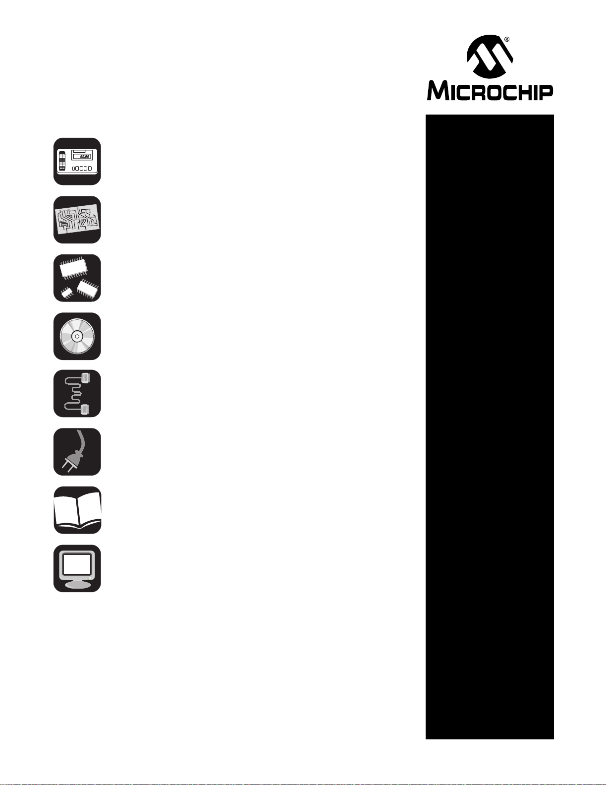
MPLAB® ICE 2000 Modular In-Circuit Emulator
Microchip’s
universal
MPLAB ICE
for PICmicro
MCUs has
been designed
with user
requirements
in mind. The
system is
small, portable,
lightweight and
offers improved performance and value. For quick
hook-up to portable or desktop PCs, MPLAB ICE easily
connects to the parallel (printer) port.
Interchangeable processor modules allow the system
to be easily configured to emulate different processors.
This modular system consists of an emulator pod, a
processor module, a device adapter and a transition
socket (optional). Also included is Microchip’s MPLAB
Integrated Development Environment (IDE) featuring
MPASM
editor, symbolic debugger, and project manager with
built-in support for high-level languages that support
the Common Object Description format (i.e., MPASM
assembler, MPLAB C17 and MPLAB C18).
MPLAB ICE 2000 is a premium quality emulator
system providing full-speed emulation, low-voltage
operation, 32K x 128-bit trace and unlimited
breakpoints. Complex triggering of the MPLAB ICE
2000 provides sophisticated trace analysis and
precision breakpoints. The trace analyzer captures
real-time execution addresses, opcodes and read/
writes of external data. It also traces all file register
RAM usage showing internal addresses and data
values, as well as all accesses to special function
registers, including I/O, timers and peripherals.
™
macro assembler, MPLAB programmer’s
®
Triggers and breakpoints can be set on single events,
multiple events and sequences of events. The MPLAB
ICE 2000 analyzer is fully transparent and does not
require halting the processor to view the trace. In
addition, MPLAB ICE 2000 supports code coverage
profiling.
Features
• Full Speed Real-Time Emulation
• Low Voltage Emulation: 2.0V to 5.5V
• Trace Memory: 32K x 128-bit
• Break/Trigger on Internal Registers
• Program Address Software Breakpoints
• Complex Break/Trigger on Logic: Program
Address and Data; Internal Register Address and
Data; Access Type; and Eight External Inputs
• One External Input and Output Logic Analyzer
Trigger
• Multi-level Trigger (4 levels)
• Pass and Delay Counters
• Time Stamp
• Programmable Clock: 32 kHz to 40 MHz
• Logic Probes
• Parallel (printer) Port Communications
• Code Coverage Profiling
.
MPLAB ICE 2000 In-Circuit Emulator Contents
• MPLAB ICE 2000 with Tripod
• MPLAB IDE Software and Documentation CD
• Logic Probes
• Parallel Cable
• Power Supply
Ordering Part Number:
ICE2000 MPLAB ICE 2000 Modular In-Circuit Emulator Pod (see ordering instructions on page 75)
© 2003 Microchip Technology Inc. DS30177R-page 5
Page 8
Development Tools Ordering Guide
NEW
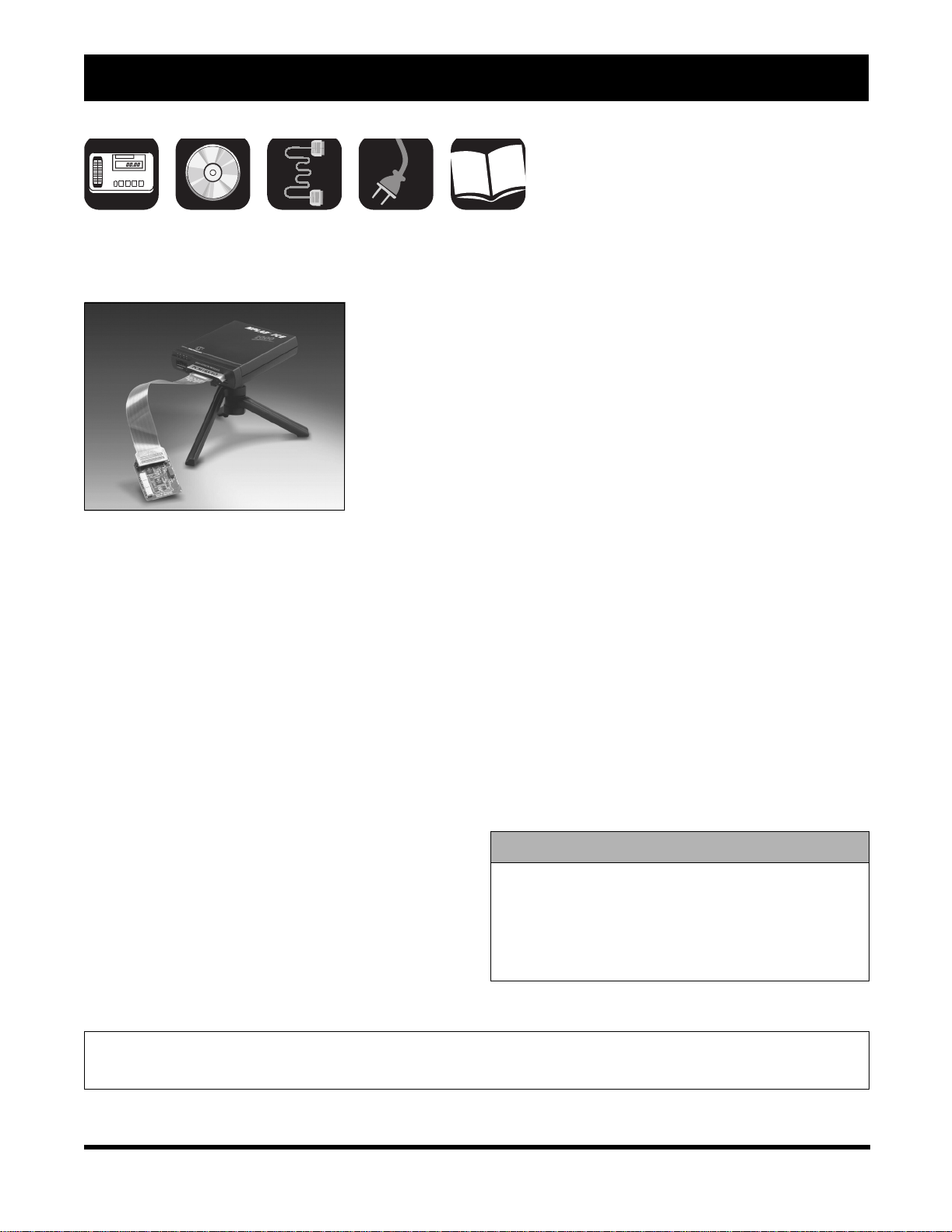
MPLAB® ICE 4000 Modular In-Circuit Emulator
The MPLAB
ICE 4000
in-circuit emulator
is intended to
provide the product
development
engineer with a
complete
microcontroller
design tool set for
high-end PICmicro
microcontrollers. Software control of the emulator is
provided by the MPLAB Integrated Development
Environment, which allows editi ng , build in g,
downloading and source debugg ing from a single
environment.
The MPLAB ICE 4000 is a premium emulator system
providing the features of MPLAB ICE 2000, but with
increased emulation memory and high speed
performance for dsPIC30F and PIC18XXXX devices.
Its advanced emulator features include complex
triggering and timing, up to 2 MB of emulation memory ,
and the ability to view variables in real time.
The MPLAB ICE 4000 in-circuit emulator system has
been designed as a real-time emulation system with
advanced features that are typically found on more
expensive development tools. The PC platform and
Microsoft Windows
chosen to best make these features available in a
simple, unified application.
®
32-bit operating system were
®
Features
• Full Speed Emulation
• Low voltage emulation down to 1.8 volts (or
device limit)
• 64K deep x 216-bit wide Trace Memory
• Up to 2 MB of addressable memory
• Unlimited breakpoints
• Complex break, trace and trigger logic
• Multi-level trigger up to 4 levels
• 48-bit time stamp
• Stopwatch
• External inputs
• External ou t p ut to sy nc with othe r instrumen tation
• USB port and parallel port* connection to PC
*Feature to be available later with software upgrade
MPLAB ICE 4000 In-Circuit Emulator Contents
• MPLAB ICE 4000
• MPLAB IDE Software and Documentation CD
•Flex Cable
• Logic Probes
•USB Cable
• Power Supply
Ordering Part Number:
ICE4000 MPLAB ICE 4000 Modular In-Circuit Emulator (see ordering instructions on page 75)
DS30177R-page 6 © 2003 Microchip Technology Inc.
Page 9
MPLAB® ICE 2000/4000 Replacement Accessories
Emulator Systems
Device Adapter Plugs
Device adapter plugs are available as replacement
accessories. The table below lists the replacement part
number.
Model
Part Number
ACICE0201 MPLAB ICE 8P 300 mil adapter plug
ACICE0202 MPLAB ICE 18P 300 mil adapter plug
ACICE0203 MPLAB ICE 20P 300 mil adapter plug
ACICE0204 MPLAB ICE 28P 300 mil adapter plug
ACICE0205 MPLAB ICE 28P 600 mil adapter plug
ACICE0206 MPLAB ICE 40P 600 mil adapter plug
ACICE0207 MPLAB ICE 14P 300 mil adapter plug
Description
Transition Headers
Transition socket headers can be purchased
separately in the event that a customer needs
additional headers. The table below lists the headers
available.
Model
Part Number
ACICE0301 8P SOIC Header
ACICE0302 14P SOIC Header
ACICE0303 18P SOIC Header
ACICE0305 20P SOIC Header
ACICE0306 28P SOIC Header
ACICE0307 28P SSOP Header
Description
MPLAB ICE 2000 Replacement Accessories
Model
Part Number
ACICE0103 MPLAB ICE 2000 Power Supply
ACICE0104 MPLAB ICE 2000 Logic Probes
ACICE0105 MPLAB ICE 2000 Parallel Cable
ACICE0106 MPLAB ICE Tripod
ACICE0107 MPLAB ICE 2000 Flex Cable
Description
MPLAB ICE 4000 Replacement Accessories
Model
Part Number
ACICE0401 MPLAB ICE 4000 Power Supply
ACICE0402 MPLAB ICE 4000 Logic Probes
ACICE0403 MPLAB ICE 4000 Slim Parallel Cable
ACICE0106 MPLAB ICE Tripod
ACICE0407 MPLAB ICE 4000 Flex Cable
Extra logic probe hooks can be purchased from:
E-Z-Hook: (800) 995-HOOK
Part Number: XM25
Description: Micro Hook Adapter with 0.025
square pin
Description
© 2003 Microchip Technology Inc. DS30177R-page 7
Page 10

Development Tools Ordering Guide
NOTES:
DS30177R-page 8 © 2003 Microchip Technology Inc.
Page 11

Key to Kit Contents
Enclosed Development Tool
July 2003
Electronic Board
Samples
CD
Hook-up Cable(s)
Power Supply
SOFTWARE TOOLS
Printed Documentation
WWW
2003 Microchip Technology Inc. DS30177R-page 9
World Wide Web
Page 12

Development Tools Ordering Guide
NOTES:
DS30177R-page 10 2003 Microchip Technology Inc.
Page 13

Software Tools
WWW
MPLAB® Integrated Development Environment (IDE)
MPLAB IDE gives PICmicro® MCU users the flexibility to
edit, compile and debug from a single user interface.
MPLAB IDE allows you to write, debug and optimize
the PICmicro MCU applications for firmware product
designs. MPLAB IDE is a Windows
development platform featuring a project manager and
program text editor, a user-configurable toolbar
containing four pre-defined sets and a status bar which
communicates editing and debugging information.
MPLAB IDE is the common user interface for Microchip
development systems tools including MPLAB Editor,
MPASM™ Assembler, MPLAB SIM Software
Simulator, MPLIB™ Library, MPLINK™ Linker, MPLAB
C17 C Compiler, MPLAB C18 C Compiler, MPLAB ICE,
PICSTART
PRO MATE
Additional products may become available as add-on
tools in the future.
The MPLAB IDE desktop provides the development
environment and tools for developing and debugging
your application as a project, allowing you to quickly
move between different development and debugging
modes. With the MPLAB IDE environment, you can
write and debug your source code, automatically locate
errors in source files for editing, debug with breakpoints
based on internal register values, watch the program
flow with MPLAB SIM (software simulator) or MPLAB
ICE, make timing measurements with a “time stamp,”
view variables in watch windows, program firmware
with PICSTART Plus or PRO MATE II programmers
and find quick answers to questions from the MPLAB
IDE on-line help.
®
Plus Development Programmer,
®
II Programmer and MPLAB ICD.
®
based
Features
• Full featured, color coded text editor
• Easy to use project manager with visual display
• Source level debugging
• Enhanced source level debugging for ‘C’
structures, automatic variables, etc.
• Customizable toolbar and key mapping
• Dynamic status bar displays processor condition
at a glance
• Context sensitive, interactive on-line help
• Integrated MPLAB SIM instruction simulator
• User interface for PRO MATE II and PICSTART
Plus device programmers
• User interface for MPLAB ICE 2000 or MPLAB
ICE 4000 In-Circuit Emulator
• User interface for MPLAB ICD 2 In-Circuit
Debugger
Ordering Part Number:
Available on the Microchip web site at: www.microchip.com.
2003 Microchip Technology Inc. DS30177R-page 11
Page 14
Development Tools Ordering Guide
WWW
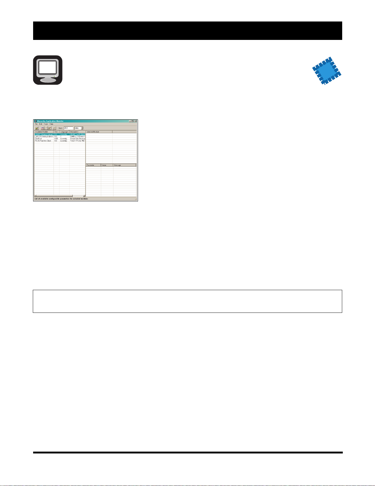
Application Maestro™ Software
The Microchip
Application
Maestro
Software is a
stand-alone
software tool
that allows
users to
configure and
incorporate a
range of
pre-written
firmware modules into their applications. Its heart is a
collection of modules developed by Microchip
Technology for use with its PICmicro
Starting from a graphic interface, the user selects one
or more available modules, then configures the
parameters for each. When this is complete, the
Application Maestro Software then generates code that
can be incorporated into the user’s application project,
using MPLAB
environment.
®
IDE or any compatible development
®
microcontrollers.
It is important to note that the Application Maestro
Software is not a plug-in or add-on to the MPLAB line
of development tools; it is a separate item in its own
right. Application Maestro Software also differs from
other librarian systems, such as MPLIB™ Library,
because it does more than archive and manage related
files for a single software project. Instead, it manages a
library of ready-to-configure modules that the user
customizes to their needs, and creates the necessary
files for inclusion in the user’s projects on demand.
NEW
Ordering Part Number:
Available on the Microchip web site at: www.microchip.com (Free Download).
DS30177R-page 12 2003 Microchip Technology Inc.
Page 15
Software Tools
WWW
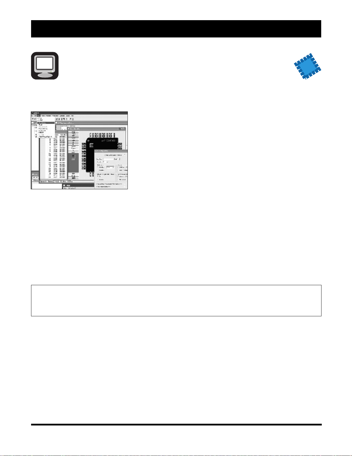
MPLAB® Visual Initializer Software
Configuring a
powerful 16-bit
MCU or DSP
can be a
complex and
challenging
task, but not
with the
dsPIC30F.
Microchip’s
MPLAB Visual
Initializer
allows users to configure the entire processor
graphically, and when complete, a mouse click
generates code usable in Assembly or C programs.
MPLAB Visual Initializer does extensive error checking
on assignments and conflicts on pins, memories and
interrupts as well as selection of operating conditions.
The generated code files are seamlessly integrated
with the rest of the application code through MPLAB
project.
Features
• Drag and drop feature selection
• One click configuration
• Extensive error checking
• Generates initialization code
• Integrates seamlessly in MPLAB project
• Printed reports eases project documentation
requirements
NEW
The detailed reports on resource assignment and
configuration simplifies project documentation.
Ordering Part Number:
Available on the Microchip web site at: www.microchip.com (Free Download).
Estimated Availability: Q3 2003
2003 Microchip Technology Inc. DS30177R-page 13
Page 16
Development Tools Ordering Guide
MPLAB® C17 C Compiler
MPLAB C17 provides powerful integration capabilities and ease of use.
The MPLAB C17 is a full-featured, ANSI-compliant C
compiler for the PIC17CXXX MCU family. MPLAB C17
is fully compatible with Microchip’s MPLAB IDE,
allowing source level debugging with both MPLAB ICE
and MPLAB SIM. MPLAB IDE provides a convenient,
project oriented development environment that
reduces development time.
MPLAB C17 allows code for the PIC17CXXX family to
be written in the C high-level language using powerful
PICmicro
®
MCU libraries, enabling the developer to
devote more time to the application and less time to the
details of the processor.
MPLAB C17 was designed explicitly for the
PIC17CXXX family and allows the use of a software
stack for maximum RAM reusability or can be run
without a stack for optimal code space efficiency.
MPLAB C17 provides user configurable interrupt
support macros for saving and restoring context during
interrupt handling. Libraries and interrupt handlers are
provided for multiple memory models. Libraries,
precompiled objects and linker scripts can be included
in MPLAB IDE projects along with C and Assembly
source files for use with MPLAB IDE make and build
functions.
The MPLAB C17 ANSI-compliant C compiler comes
complete with the MPLAB IDE. The IDE allows you to
quickly move between different development and
debugging modes. For example, you can quickly
advance from software debugging with MPLAB SIM
simulator to hardware debugging with MPLAB ICE.
MPLAB C17 has implemented extensions to the C
language to provide specific support for Microchip’s
PICmicro MCU environment.
These C library extensions include:
A/D Converter Input Capture
SPI™ Timers
2
I
C™ I/O Port
Reset External LCD
Software I2C Software USART
Relay Memory/String Manipulation
32-bit Math Library Interrupt Support Macros
USART Character Classificat ion
Pulse Width Modulation Number/Text Conversion
Software SPI
MPLAB C17 will run on any 486 or better PC, on
MS-DOS 5.0+ or as a native 32-bit Windows
Windows NT
.
®
executable.
®
95 or
MPLAB C17 C Compiler Contents
• MPLAB C17 C Compiler Software
• MPLAB IDE Software and Documentation CD
• MPLAB C17 Compiler User’s Guide and
MPLAB C17 Compiler Libraries Manuals
• Complete Documentation
Ordering Part Number:
SW006010 MPLAB C17 C Compiler
A 60-day free demo is available from the Microchip web site at www.microchip.com.
DS30177R-page 14 2003 Microchip Technology Inc.
Page 17
MPLAB® C18 C Compiler
Software Tools
The MPLAB C18 is a full-featured ANSI-compliant C
compiler for the Microchip Technology PIC18CXXX
family of PICmicro
compatible with Microchip’s MPLAB IDE, allowing
source level debugging with both the MPLAB ICE and
the MPLAB SIM simulator. MPLAB C18 provides a
convenient, project oriented development environment
that reduces development time.
MPLAB C18 allows code for the PIC18CXXX family to
be written in the C high-level language using powerful
PICmicro MCU libraries, enabling the developer to
devote more time to the application and less time to the
details of the processor.
MPLAB C18 was designed explicitly for the
PIC18CXXX family and allows the use of a software
stack for maximum RAM reusability.
MPLAB C18 provides user configurable interrupt
support for saving and restoring context during
interrupt handling. Libraries are provided for multiple
memory models. Libraries, precompiled objects and
linker scripts can be included in MPLAB C18 projects
along with C and Assembly source files for use with
MPLAB C18 make and build functions.
The MPLAB C18 ANSI-compliant C compiler comes
complete with the MPLAB IDE. The IDE allows you to
quickly move between different development and
debugging modes. For example, you can quickly
advance from software debugging with MPLAB SIM
simulator to hardware debugging with MPLAB ICE.
®
MCUs. MPLAB C18 is fully
MPLAB C18 has implemented extensions to the C
language to provide specific support for Microchip’s
PICmicro MCU environment.
These C library extensions include:
A/D Converter Input Capture
SPI™ Timers
2
I
C™ I/O Port
Reset External LCD
Software I2C Software USART
Relay Memory/String Manipulation
32-bit Math Library Interrupt Support Macros
USART Character Classificat ion
Pulse Width Modulation Number/Text Conversion
Software SPI
MPLAB C18 will run on any 486 or better PC, as a
native 32-bit Windows
executable.
MPLAB C18 C Compiler Contents
• MPLAB C18 C Compiler Software
• MPLAB IDE Software and Documentation CD
• MPLAB C18 Compiler User’s Guide and
MPLAB C18 Compiler Libraries Manuals
• Complete Documentation
®
95 or Windows NT®
Ordering Part Number:
SW006011 MPLAB C18 C Compiler
A 60-day free demo is available from the Microchip web site at www.microchip.com.
2003 Microchip Technology Inc. DS30177R-page 15
Page 18
Development Tools Ordering Guide
MPLAB® C30 C Compiler
NEW
The MPLAB C30 C compiler is a fully ANSI compliant
product with standard libraries for the dsPIC
architecture. It it highly optimizing and takes advantage
of many dsPIC architecture specific features to provide
efficient software code generation. MPLAB C30 also
provides extensions that allow for excellent support of
the hardware, such as interrupts and peripherals. It is
fully integrated with the MPLAB IDE for high level,
source debugging.
®
Features
• 16-bit native data types
• Efficient use of register based, 3-operand
instructions
• Complex Addressing mode s
• Efficient multi-bi t shift operations
• Efficient signed/unsigned comparisons
Ordering Part Number:
SW006012 MPLAB C30 C Compiler
Estimated Availability: Q3 2003
MPLAB C30 comes complete with its own assembler,
linker and librarian. These allow the user to write Mixed
mode C and assembly programs and link the resulting
object files into a single executable file.
MPLAB C30 C Compiler Contents
• MPLAB C30 C Compiler Software
• MPLAB IDE Software and Documentation CD
• MPLAB C30 Compiler User’s Guide (on CD)
and Complete Documentation
DS30177R-page 16 2003 Microchip Technology Inc.
Page 19
dsPIC30F Software Libraries
Software Tools
NEW
Math Library
This IEEE-754 compliant library provides ANSI C
standard math functions for floating-point and double
precision data types. These routines have been
optimized to provide the smallest code size. The library
functions can be called by Assembly or C code. Key
functions include:
• sin, cos, tan
• asin, acos, atan
• ln, log10, sqrt, pow, alog10
• ceil, floor, mod, frexp
DSP Algorithm Library
This extensive DSP building block library is fully
optimized in assembly code for execution speed. The
DSP functions can be used in Assembly or C. Scope
includes:
• Matrix and vector functions
• Filtering functions – IIR, FIR, LMS
• Transform functions – FFT, DCT
• Correlation, Convolution and Window functions
Peripheral Driver Library
This library, containing over 270 C functions, helps you
set up and operate the hardware peripheral modules
including:
• 10-bit and 12-bit ADC
• UART, SPI™ and I
• Motor control PWM and QEI
• General purpose timers
• Input capture and Output compare
• Reset/control
• External and Change Notificati on int erru pts
•CAN
• DCI
• External LCD drivers - also included in the library
2
C™
Ordering Part Number:
SW300020 dsPIC30F Math Library
SW300021 dsPIC30F Peripheral Driver Library
SW300022 dsPIC30F Algorithm Library
Estimated Availability: Q3 2003
2003 Microchip Technology Inc. DS30177R-page 17
Page 20
Development Tools Ordering Guide
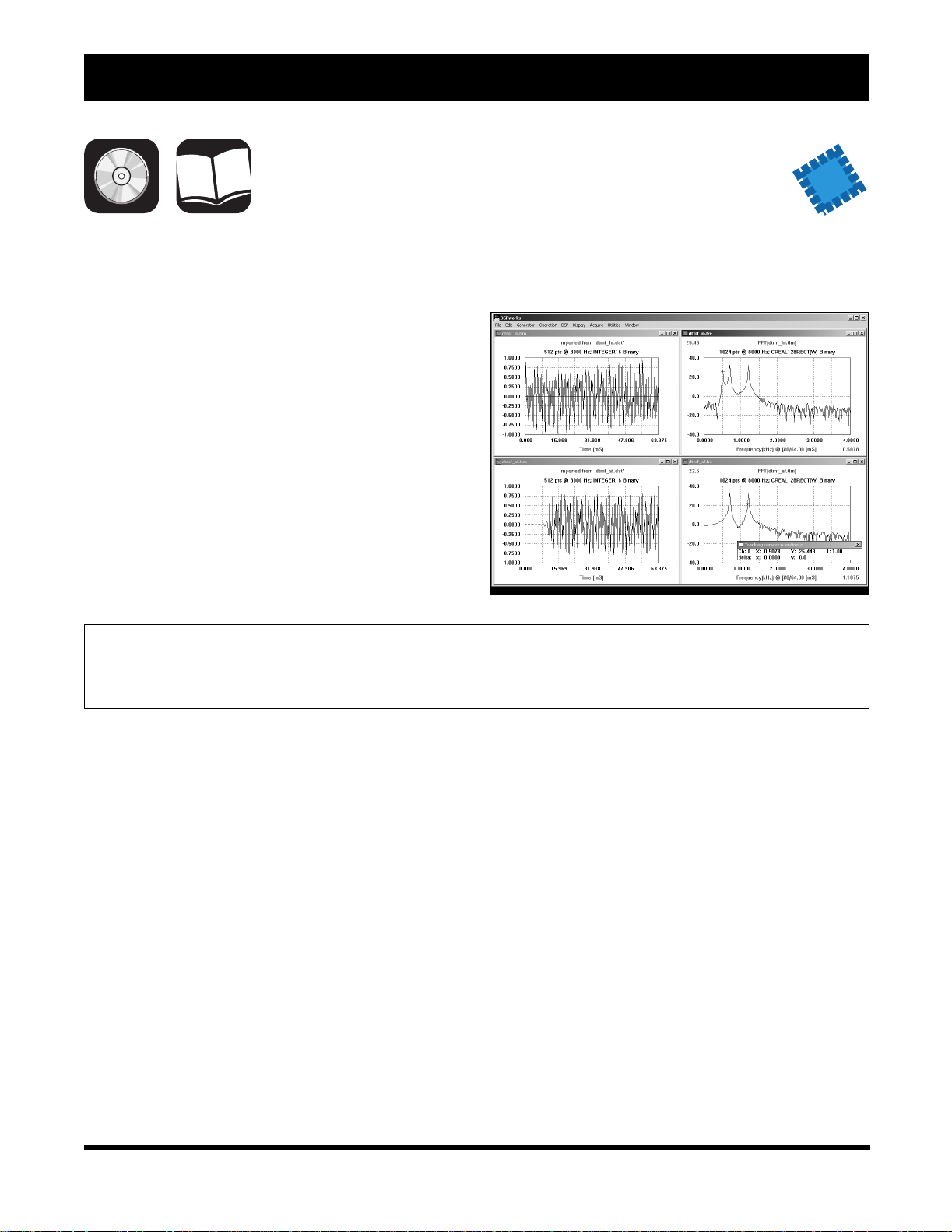
dsPICworks™ Visual Algorithm Analyzer
dsPICworks Visual DSP tool makes it easy to evaluate
and analyze DSP algorithms. A variety of DSP
operations can be run and data analyzed in the time or
frequency domain.
Features
• Visually analyze time and frequency domain data
• DSP Operations: FFT, convolution, correlation
• Waveform synthesis
• Real-time data acquisition capabilities
• Import data directly from MPLAB IDE
NEW
Ordering Part Number:
SW300023 dsPICworks – Visual Algorithm Analyzer
Estimated Availability: Q3 2003
DS30177R-page 18 2003 Microchip Technology Inc.
Page 21
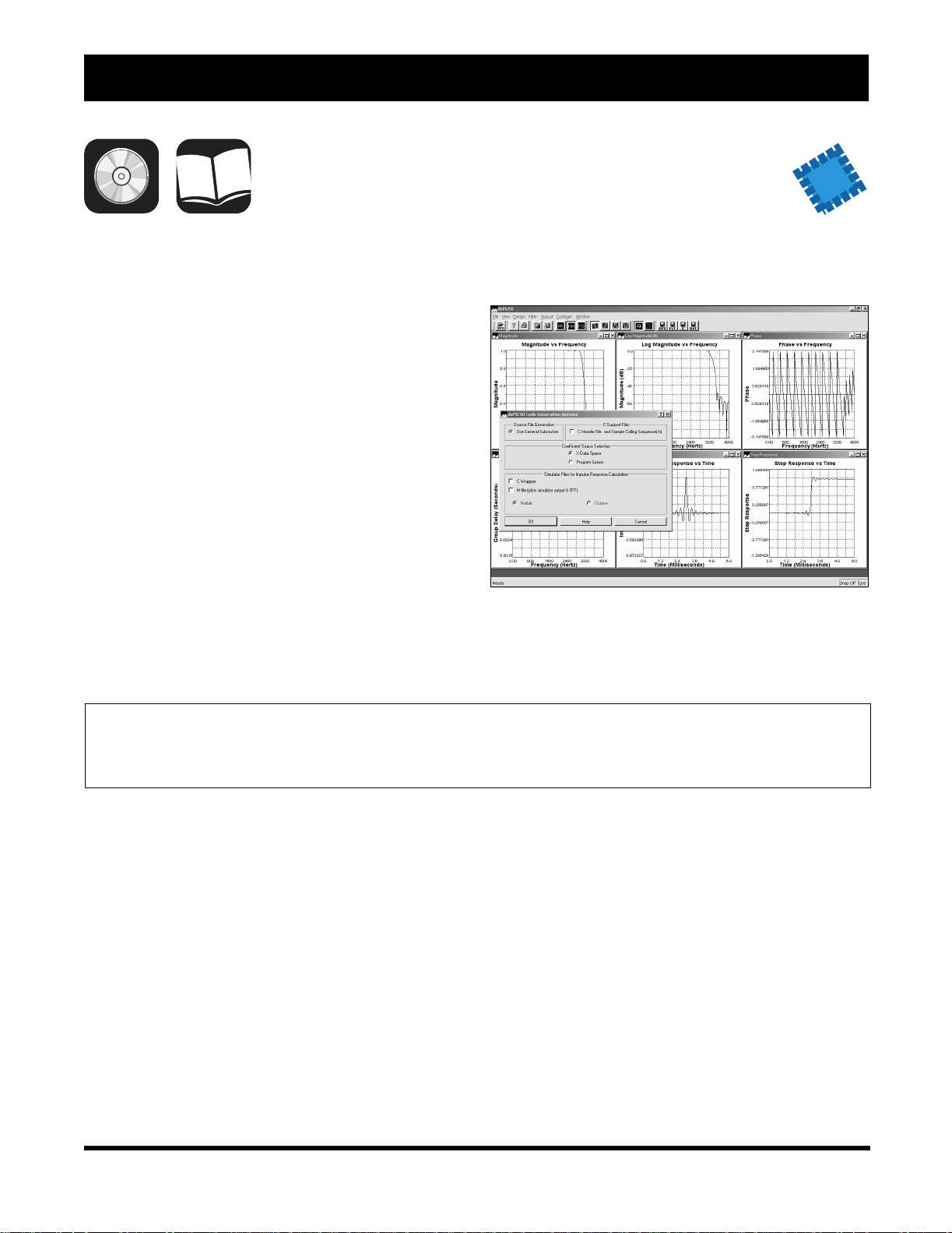
Visual Digital Filter Designer
The Visual Filter Designer tool for dsPIC®
microcontrollers makes designing and analyzing Finite
Impulse Response (FIR) and Infinite Impulse
Response (IIR) filters easy. Enter frequency
specifications and filter code and coefficients are
generated automatically. Graphical output windows
provide the desired filters characteristics.
Features
• Lowpass, highpass, bandpass and bandstop filter
support
• FIR filters with up to 513 taps
• IIR filter with up to 10 taps for lowpass and
highpass filters
• IIR filter with up to 20 taps for bandpass and
bandstop filters
• Generates dsPIC30F assembly code and filter
coefficient files for export to MPLAB IDE or
MPLAB C30 C Compiler
Software Tools
NEW
Ordering Part Number:
SW300001 Visual Digital Filter Designer
Estimated Availability: Q3 2003
2003 Microchip Technology Inc. DS30177R-page 19
Page 22

Development Tools Ordering Guide
KEELOQ® License CD
The KEELOQ License CD contains KEELOQ application
notes, decoder software and the K
Toolkit. Also included are K
EELOQ data sheets,
development tools documentation and MPLAB
EELOQ Software
®
IDE
software.
The K
EELOQ Software Toolkit is a tool that is designed
to be used by a K
code. The toolkit allows the user to receive K
transmissions from the K
(DM303006) and the K
EELOQ system developer to debug
EELOQ
EELOQ Evaluation Kit II
EELOQ Transponder Evaluation
Kit (DM303005).
Ordering Part Number:
DS40038 K
EELOQ License CD
Available from Microchip at: lit_inquiry@microchip.com (Americas & Canada),
euro.inquiry@microchip.com (Europe) or asia.inquiry@microchip.com (Far East).
The K
EELOQ Decoder software is typically used as the
starting point of a decoder design. The software is fully
described in the application notes accompanying the
software.
DS30177R-page 20 2003 Microchip Technology Inc.
Page 23
Software Tools
WWW
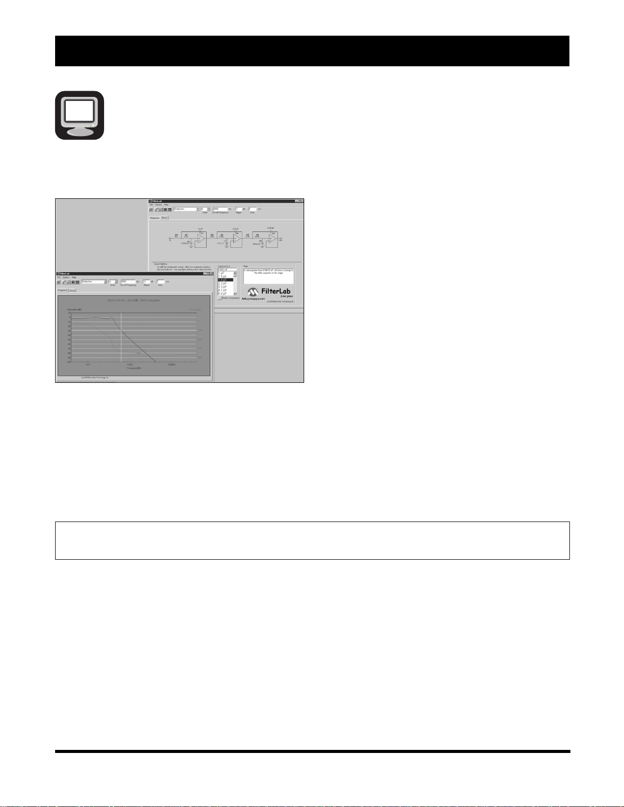
FilterLab® Active Filter Software Design Tool
Features
• Multiple Filter Order and Responses with Gain
Option
- Ability to select Bessel, Butterworth or
Chebyshev filter respon se
- Up to 8th-order filters can be simulated
- Circuit diagram and component values given
• Bode Plot with Phase Margin
- Resultant Bode plot generated
• Circuit Implementation
- Standard 1 percent resistors
- Standard capacitor values generate and user
adjustable
- Circuit configuration: Sallen-Key (noninverting)
FilterLab is an innovative software tool that simplifies
active filter design. The FilterLab active filter software
design tool provides full schematic diagrams of the
filter circuit with component values and displays the
frequency response.
or multiple feedback (inverting)
• Spice Model Generated
- Spice Model of entire filter generated
- Allows for streamline of simulations
• Anti-Aliasing Wizard
- Filter optimization for Analog-to-Digital
Converter based on bit resolution and sample
rate.
Ordering Part Number:
Available on the Microchip web site at www.microchip.com (Free Dowload).
2003 Microchip Technology Inc. DS30177R-page 21
Page 24

Development Tools Ordering Guide
WWW
Total Endurance™ Software Model
Microchip’s revolutionary Total Endurance Software
Model provides electronic system designers with
unprecedented visi bili ty into Serial EEPROM-based
applications. This adv anc ed so ftware mod e l (with a
very friendly user interface) eliminates time and
guesswork from Serial EEPROM-based designs by
accurately predicting the device’s performance and
reliability within a user-defined application
environment. Design trade-o ff analysis which former l y
consumed days or weeks can now be performed in
minutes – with a level of accuracy that delivers a truly
robust design.
With Microchip’s Total Endurance Software Model,
users may input the following application parameters:
• Serial EEPROM device type
• Bytes to be written per cycle
• Cycling mode – byte or page
• Data pattern type – random or worst-cast
• Temperature in °C
• Erase/Write cycles per day
• Application lifetime or target PPM level
The model will respond with FIT rate, PPM level,
application life and plot of the PPM level versus
number of cycles. The model is available in both
MS-DOS and Windows
®
versions.
Features
• Automatic or manual recalculation
• Real-time update of data
• Full-screen or windowed graphical view
• Hypertext on-screen help
• Key or slide-bar entry of parameters
• On-screen editing of parameters
• Single-click copy of plot to clipboard
• Numeric export to delimited text file
• On-disk Endurance Tutorial
Ordering Part Number:
Available on the Microchip web site at www.microchip.com (Free Dowload).
DS30177R-page 22 2003 Microchip Technology Inc.
Page 25

K
ey to Kit Contents
Enclosed Development Tool
July 2003
PROGRAMMER SYSTEMS
Electronic Board
Samples
PICmicro®
CD
Hook-up Cable(s)
Power Supply
Printed Documentation
WWW
2003 Microchip Technology Inc. DS30177R -page 23
World W ide Web
Page 26

Development Tools Ordering Guide
NOTES:
DS30177R-page 24 2003 Microchip Technology Inc.
Page 27
PICmicro® Programmer Systems
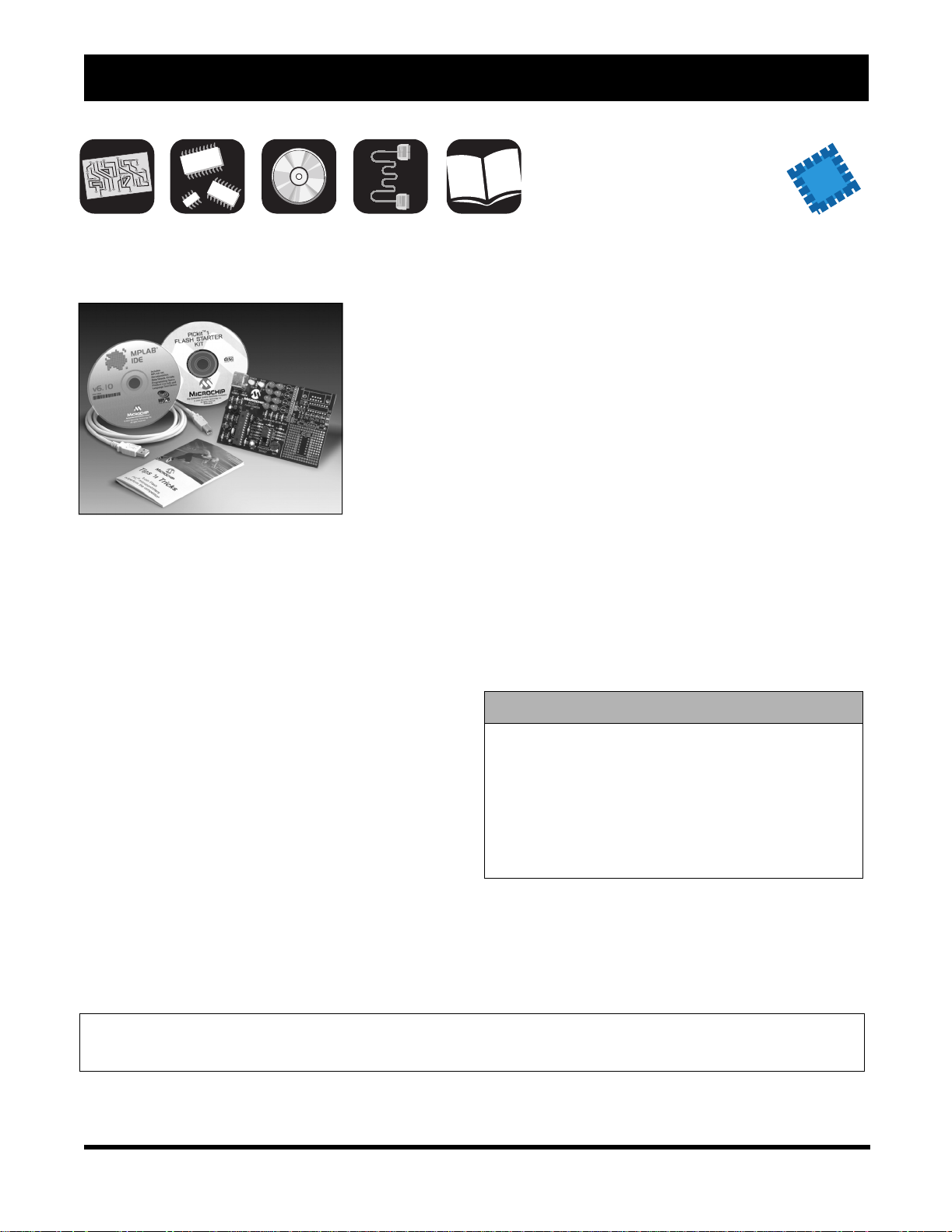
PICkit™ 1 FLASH Starter Kit
NEW
The PICkit 1
FLASH Starter
Kit is a
low-cost
development
kit with an
easy to use
interface for
programming
Microchip’s
8/14-pin
FLASH
of microcontrollers. This starter kit is designed to help
the user get up to speed quickly using PIC
microcontrollers.
The kit provides everything needed to program,
evaluate and develop applications using Microchip’s
powerful 8/14-pin FLASH family of microcontrollers.
Instructions are provided in a series of seven tutorials
that cover I/O, Interrupts, A/D Converters,
Comparators, Data T ables and Timers. All source code
files for the tutorials are furnished.
Code development and debugging is performed using
Microchip’s powerful MPLAB
Environment (IDE). The MPLAB IDE is a seamless,
integrated software development environment that
includes a MPASM™ macro assembler, MPLAB SIM
software simulator with symbolic debugger, colorcoded source editor, project manager with high-level
language debugging and concurrent support for
development tools, includi ng low- c ost in-ci rcu it
debuggers, full-featured real-time emulators and
programmers. The consistent and easy-to-use graphic
user interface of the MPLAB desktop allows for rapid
switching between development, debugging and
programming modes within a project.
®
Integrated Development
®
family
Features
• Small 3" x 4.5" circuit board with snap-off
prototyping board
• Easy to use Wi ndows
programming Microchip's 8/14 pin FLASH family
of microcontrollers
• Seven sequential tutorials written in both
Assembly and HI-TECH C demonstrate how to
use Microchip’s 8/14 pin FLASH family of
microcontrollers
• Microchip’s Tips ‘n Tricks Booklet provides
efficient, low-cost design techniques using
Microchip FLASH microcontrollers
• PICkit 1 User Guide (included on CD)
• Microchip's MPLAB IDE software for a complete
code development environment
• HI-TECH PICC™ LITE C Compiler (contained on
the MPLAB CD)
PICkit 1 FLASH Starter Kit Contents
• PICkit 1 Circuit Board with 8-pin PIC12F675
• PICkit 1 FLASH Starter Kit CD
• MPLAB IDE (Integrated Development
Environment) CD
• Software and Hardware
FLASH PIC Microcontrollers Booklet
• USB Interface Cable
®
programming interface for
“Tips ‘n Tricks” for 8-pin
Ordering Part Number:
DV164101 PICkit 1 FLASH Starter Kit
2003 Microchip Technology Inc. DS30177R-page 25
Page 28
Development Tools Ordering Guide
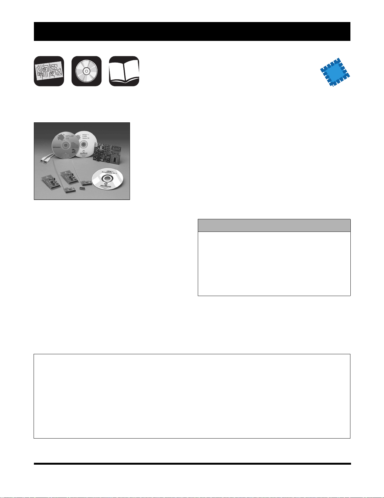
rfPIC™ Development Kit 1
NEW
The rfPIC
Development Kit
provides design
engineers with
an easy way
to evaluate
unidirectional
remote sense and
control wireless
links based on the
rfPIC12F675 and
rfRXD0420/0920 devices. The kit is based on the
popular PICkit™ 1 FLASH Starter Kit and consists of
modular building blocks for different transmitters and
receivers that can be utilized for prototype systems or
to evaluate different options using Microchip products.
The receiver modules are based on the rfRXD0420
and rfRXD0920 devices and are available in two
options supporting 315 MHz ASK and 433 MHz ASK.
These modules plug directly into the PICkit 1
Development board offering an easy way to evaluate
the different receiver modules with Microchip’s 8- and
14-pin FLASH PIC
interface to a PC. The modules are also available for
sale separately to allow a number of prototypes based
on the same module without having to do an actual RF
design. The design files for these modules are
available to allow easy integration of the designs into a
system.
®
microcontrollers as well as a USB
The transmitter modules are based on the
rfPIC12F675 devices and support the same frequency
and modulation formats as the receivers. The
transmitter modules feature button inputs for remote
control functions as well as analog input to allow
evaluation of the A/D and comparator peripherals on
the rfPIC12F675. Code development is achieved with
Microchip’s MPLAB Integrated Development
Environment (IDE). The microcontroller is easily
programmed using the PICkit 1, with modules plugging
into the PICkit in a similar manner as the receiver
modules.
rfPIC Development Kit 1 Contents
• PICkit™ 1 FLASH Starter Kit
• 433.92 MHz Transmitter
• 315 MHz Transmitter
• 433.92 MHz Receiver
• 315 MHz Receiver
• rfPIC Software and Complete Documentation
(on CD)
Ordering Part Number:
DV164102 rfPIC Development Kit 1
AC164101 rfPIC Transmitter Module (433.92 MHz)
AC164102 rfPIC Transmitter Module (315 MHz)
AC164103 rfPIC Receiver Module (433.92 MHz)
AC164104 rfPIC Receiver Module (315 MHz)
AC164105 rfPIC Receiver Module - 5 Pack (433.92 MHz)
AC164106 rfPIC Receiver Module - 5 Pack (315 MHz)
Estimated availablilty: Q3 2003
DS30177R-page 26 2003 Microchip Technology Inc.
Page 29
PICmicro® Programmer Systems
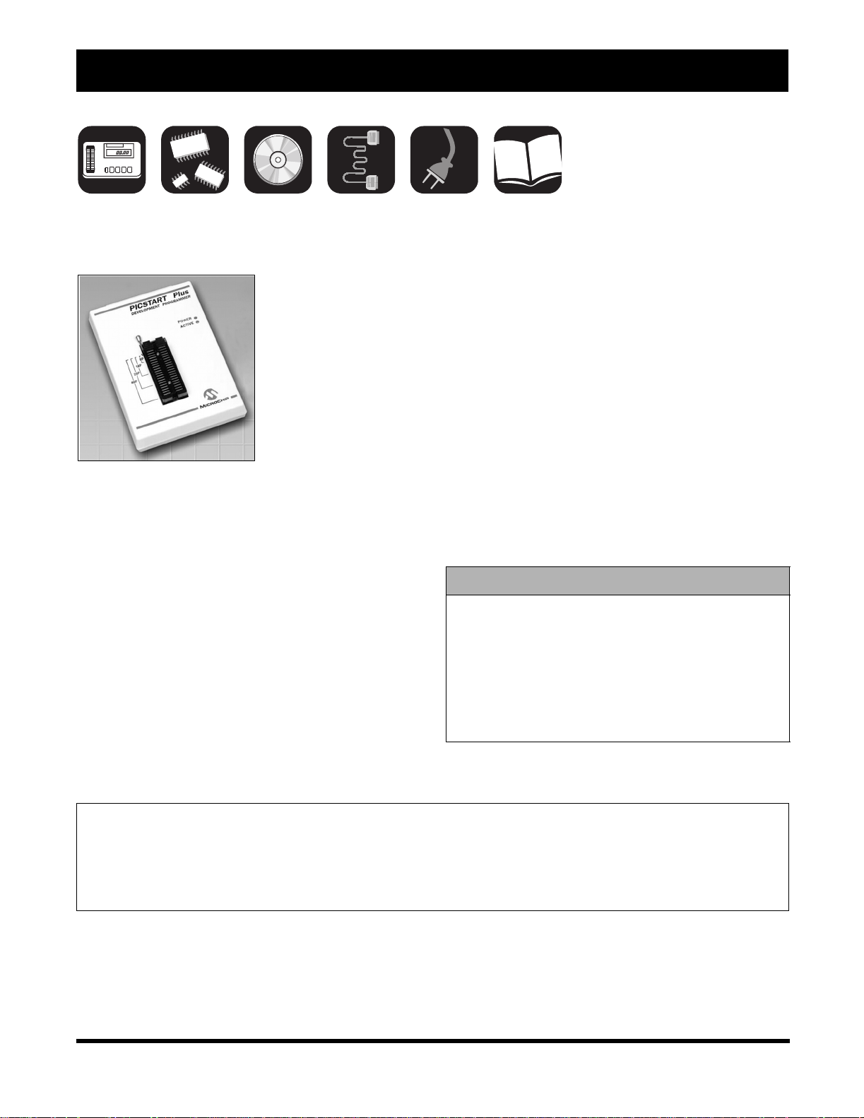
PICSTART® Plus Low-Cost Development Kit
The PICSTART Plus
programmer gives the
product developer the
ability to program user
software into any
of the supported
microcontrollers. The
PICSTAR T Plus software
running under MPLAB
IDE provides for full
interactive control over
the programmer.
The PICSTART Plus programmer provides the product
development engineer with a highly-flexible, low-cost
design tool set for all PICmicro
up to 40 pins). PLCC and QFN Adapters are available.
The CE-compliant PICSTART Plus development
programmer features a molded plastic enclosure and
special circuit design techniques to enhance ESD
protection. PICSTART Plus is a development
programmer and is not recommended for use in a
production environment.
Sample software programs are provided to help the
developer quickly become familiar with the PICSTART
Plus development system and with Microchip’s
PICmicro MCU families. Included is a limited C
compiler (PICC LITE
™
) for the PIC16F84 family.
®
MCUs (DIP packages
®
The MPASM™ macro assembler provides
programmable memory data files, listing files and
special files required for symbolic debug. The MPLAB
SIM software simulator allows the user to isolate code
problems and debug firmware designs on PICmicro
MCUs. It simulates the core functions as well as most
of the peripherals of the PICmicro MCU families. It is
particularly suitable for optimizing algorithms where
real-time emulation is not required.
The PICSTART Plus development system runs on any
PC-compatible machine under Windows
later operating system. The easy-to-use PICSTART
Plus software provides for full interactive control over
the programmer and features Microchip’s highly
acclaimed MPLAB IDE, with its built-in editor,
assembler and Windows bas ed MPLAB SIM sim ul ator.
PICSTART Plus Development Kit Contents
• PICSTART Plus Device Programmer
• Product Sample
• MPLAB IDE Software
• PICC LITE C Compiler
• RS-232 Interface Cable
• Power Supply
• Complete Documentation
®
98 SE or
Ordering Part Number:
DV003001 PICSTART Plus Programmer
AC164024 68-pin PLCC Adapter Kit for PIC16C92X and PIC17C75X
AC164027 84-pin PLCC Adapter Kit for PIC17C76X
AC164031 28-pin QFN Adapter
2003 Microchip Technology Inc. DS30177R-page 27
Page 30

Development Tools Ordering Guide
PRO MATE® II Device Programmer
CE Compliant PRO MATE II makes programming easy.
Microchip’s
PRO MATE II
Device
Programmer
makes it easy
to program th e
company’s entire
line of
PICmicro
MCUs, HCSXXX
Security
Products and 2- and 3-wire Serial EEPROMs;
operating either as a stand-alone unit or in conjunction
with a PC-compatible host system. When connected to
a host system, PRO MATE II provides an exceptionally
user-friendly interface to give the developer complete
control over the programming session. This timesaving tool comes complete with all the accessories
needed to connect to a host system including interface
cables and a universal input power supply.
In addition to the programmer unit, the PRO MATE II
system contains Microchip’s highly-acclaimed
MPLAB
Windows
PRO MATE II programmer includes full documentation
and software.
®
IDE, with its built-in editor, assembler, and
®
based MPLAB SIM simulator. The
®
The PRO MATE II software provides many user
interface features. These include a “safe mode", where
accidental corruption of master code is prevented, and
the ability to save and restore “environment” settings.
The PRO MATE II system runs with Microchip’s
popular MPLAB IDE software.
PRO MATE II is CE-compliant, meaning it meets or
exceeds all the directives for safety, emissions, ESD
and susceptibility (to radiated emission) requirements
set forth by the European Union (EU) countries.
The PRO MATE II device programmer is designed to
be robust and reliable with:
• Enhanced socket module alignment with four
auto alignment pins
• Three levels of over-current protection and
superior ESD immunity for rugged environments
• A small and compact universal IEC power supply
• Improved LCD display and buttons.
PRO MATE II Device Programmer Contents
• PRO MATE II Universal Device Programmer
Unit
• PRO MATE and MPLAB IDE Software
• RS-232 Interface Cable
• Power Supply
• Complete Documentation
Ordering Part Number:
DV007003 PROMATE II
Socket Modules are sold separately. See Development Tools Cross Reference, page 76 for socket module
ordering information.
DS30177R-page 28 2003 Microchip Technology Inc.
Page 31
PICmicro® Programmer Systems
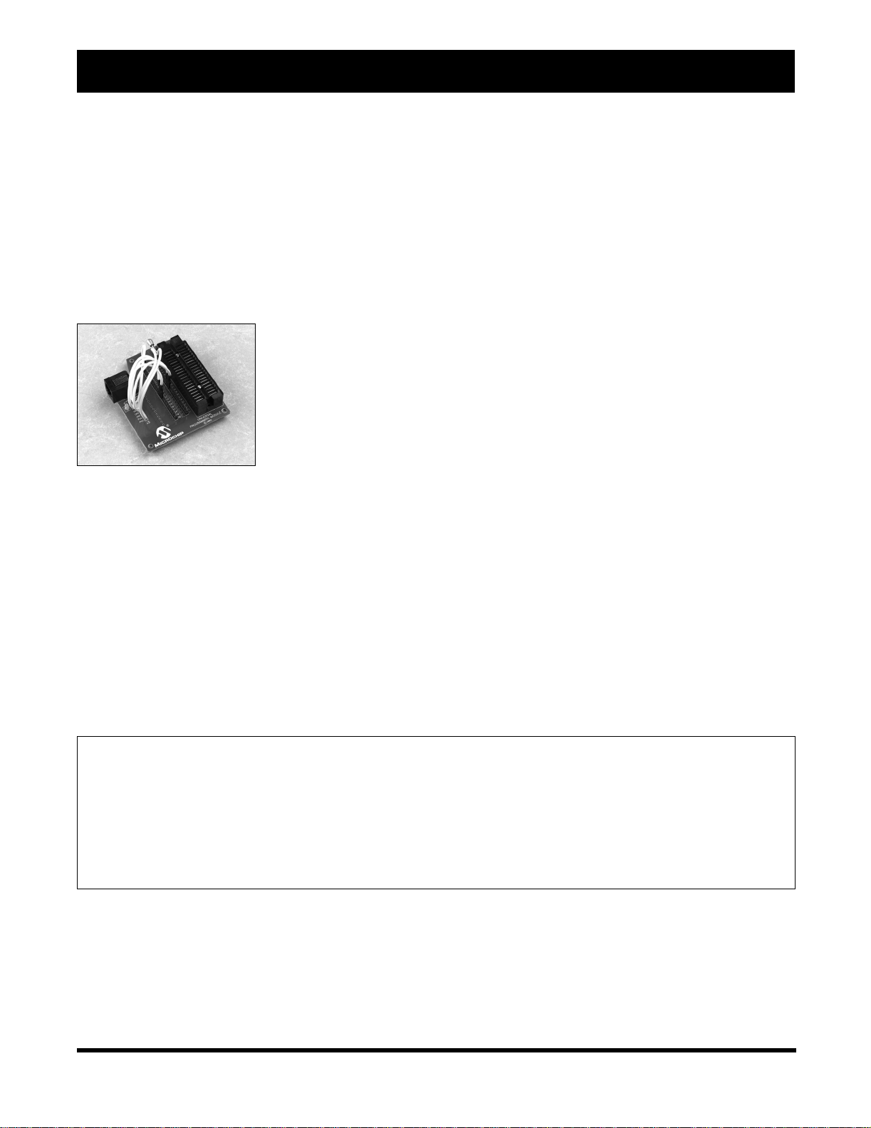
In-Circuit Serial Programming™ (ICSP™) Socket for PRO MATE® II
Microchip offers an ICSP kit that can be used with
PRO MATE
programmer. Together, these two tools allow you to
implement ICSP with minimal effort and use the ICSP
capability of Microchip's PICmicro
In-System Programming is a technique where a
programmable device is programmed after the device
is placed in a circuit board. ICSP is an enhanced ISP
technique implemented in Microchip’s PICmicro OTP
and FLASH MCUs. Using only two I/O pins to serially
input and output data makes ICSP easy-to-use and
less intrusive on the normal operation of the MCU.
Ordering Part Number:
AC004004 ICSP Socket Module
PRO MATE II is sold separately. See Development Tools Cross Reference, page 76 for more information.
II, Microchip’s universal device
®
MCUs.
The In-Circuit Serial Programming Socket module is a
complete kit including connectors, cables, and required
interface boards to allow a development engineer to
implement ICSP with PRO MATE II.
ICSP Socket for PRO MATE II Contents
• ICSP Socket
•Cable
• Power Supply
• Complete Documentation
2003 Microchip Technology Inc. DS30177R-page 29
Page 32

Development Tools Ordering Guide
Programmer Adapter Kits and Accessories
68-Pin PLCC Adapter Kit
PIC16C92X/PIC17C75X 68-Pin PLCC Adapter for
PICSTART
PIC16C92X and PIC17C75X.
®
Plus. Currently this header supports
84-Pin PLCC Adapter Kit
PIC17C6X 84-Pin PLCC Adapter for PICSTART Plus.
28-Pin QFN Adapter Kit
PIC16CXX 28-Pin QFN Adapter for PICSTART Plus and
PRO MATE
®
II programmers (with AC164012).
Ordering Part Number:
AC164024 68-Pin PLCC Adapter Kit
AC164027 84-Pin PLCC Adapter Kit
AC164031 28-Pin QFN Adapter Kit for 40-Pin ZIF Socket
AC164032 8-Pin DFN Adapter Kit
AC164033 28-Pin QFN Adapter Kit for 18-Pin ZIF Socket
AC164034 44-Pin QFN Adapter Kit
DS30177R-page 30 2003 Microchip Technology Inc.
Page 33

Key to Kit Contents
Enclosed Development Tool
Electronic Board
Samples
CD
Hook-up Cable(s)
July 2003
IN-CIRCUIT DEBUGGER
WWW
Power Supply
Printed Documentation
World W ide Web
2003 Microchip Technology Inc. DS30177R -page 31
Page 34

Development Tools Ordering Guide
NOTES:
DS30177R-page 32 © 2003 Microchip Technology Inc.
Page 35

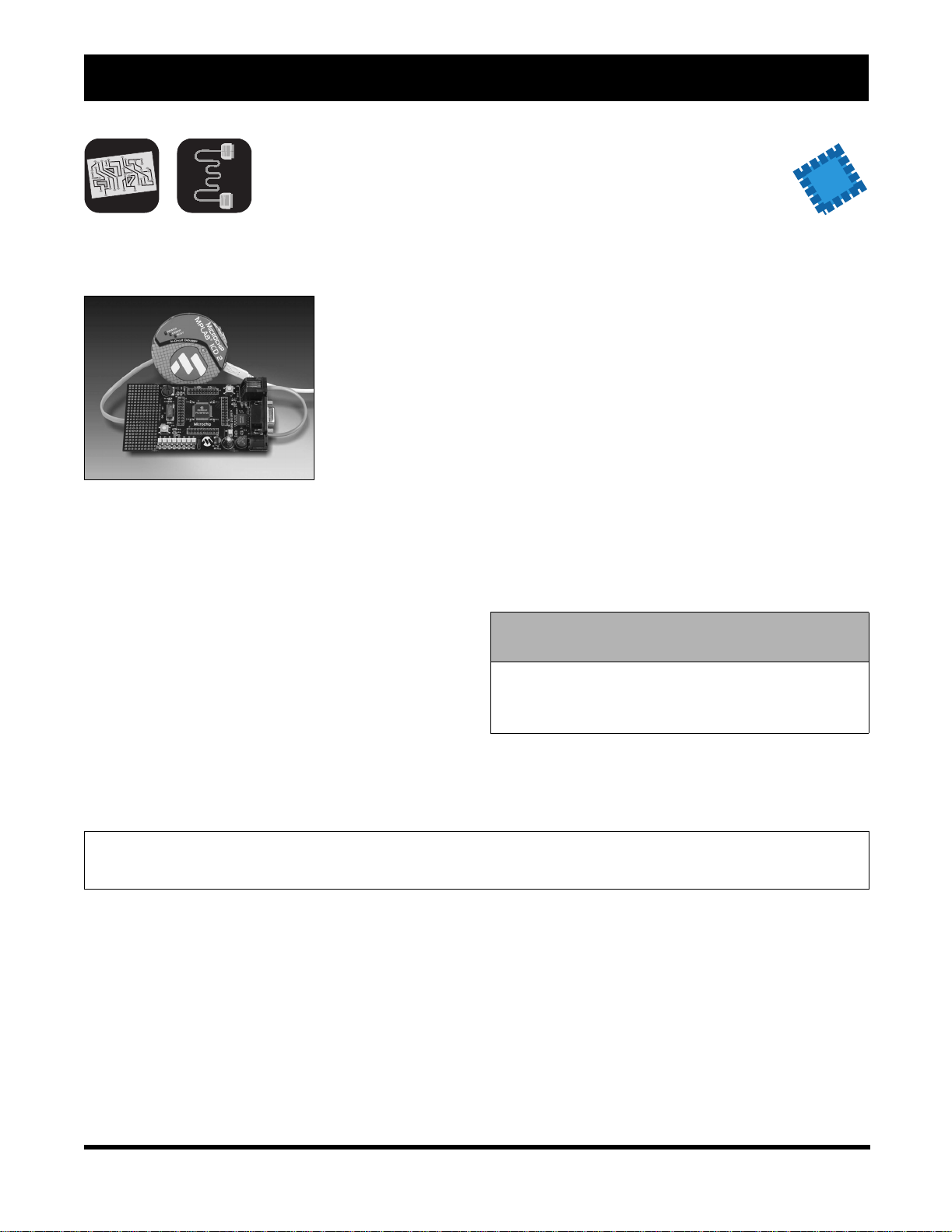
In-Circuit Debugger
MPLAB® ICD 2 In-Circuit Debugger
The MPLAB
ICD 2 module
is a low cost
development
tool that
connects
between the
PC and the
designers target
board allowing
direct in-circuit
aPICmicro
executed in real time or single step, watch variables
established, break points set, memory read/writes
accomplished and more. It can also be used as a
development programmer for the microcontrollers.
The MPLAB ICD 2 allows debugging of selected
FLASH-based Microchip microcontrollers using
MPLAB Integrated Development Environment (IDE).
This powerful graphical user interface is included with
each unit as a free tool. It is the ideal tool for embedded
controller designers who do not have the budget for a
high-cost in-circuit emulator.
®
target microcontroller. Programs can be
debugging of
Shared overhead is: one stack level, some general
purpose file registers and a small bank of program
memory when in the debug mode and two hardware
pins (RB6 and RB7) lines.
The MPLAB I CD 2 is fir mware -bas ed, wh ich al lows it to
be enhanced to support future microcontroller products
and new features extending the tool life and making it a
valued buy. Firmware downloads are available from the
Microchip web site at: www.microchip.com.
Features
• USB (Full Speed 2 Mbits/s) and RS-232 interface
to Host PC
• Real time background debugging
• Built-in over voltage/short circ uit m onitor
• Supports low voltage operation to 2.0 volts
• Diagnostic LED’s (Power, Busy, Error)
• Reading/Writing memory space and stack of
target microcontroller
• Erase of program memory space with verification
• Freeze on Halt
Ordering Part Number:
DV164005 MPLAB ICD 2 Module
DV164006 MPLAB ICD 2 Evaluation Kit
(Includes MPLAB ICD 2 Module, USB Cable, RS-232 Cable, Power Supply and
PICDEM™ 2 Plus Demo nstration Board - DM163022)
DV164007 MPLAB ICD 2 Module ws
(Includes MPLAB ICD 2 Module, USB Cable, RS-232 Cable and Power Supply)
2003 Microchip Technology Inc. DS30177R-page 33
(Includes MPLAB ICD 2 Module and USB Cable)
Page 36
Development Tools Ordering Guide
MPLAB® ICD 2 Accessories
RS-232 and Power Supply Kit
Universal Power Supply and Serial Cable to support
using the ICD 2 for serial communications or with the
Universal Programmer Module. These items are
included with the MPLAB ICD 2 DV164006 and
DV164007 products.
Universal Programming Module
The Universal
Programming Module is
a handy low cost tool to
support programming of
DIP packaged products
from Microchip.
It can be used in
conjunction with the
In-Circuit Debugger
(MPLAB ICD 2) to provide an easy means for
programming microcontrollers.
Seven flying leads break out the primary programming
lines needed for any microcontroller. These are
connected to the 40 breakout pins of the ZIF socket,
allowing any part to be configured to the necessary
programming lines.
MPLAB ICD 2 Header Interfaces
The header interface provides In-Circuit Debugging
capability to the 8-pin, 14-pin or 18-pin device. The
header interface is connected in place of the target
device and houses a standard MPLAB ICD 2
connector. In-circuit debugging is done via an MPLAB
ICD 2. Once the code is debugged, the debugged
software can then be programmed into the device and
installed in the board replacing the header.
MPLAB ICD Header Interface
A handy device that plugs into the existing 40-pin DIP
socket on the development board where a FLASH
based microcontroller would be. It breaks the
connection to RB5, RB6 and RB7, which are then
connected to the standard MPLAB ICD connector. This
provides access for immediate in-circuit debugging
without having accommodating hardware on your
board.
Features
• ZIF Socket
• Supports up to 40-pin devices from 300 to 600 mil
width
• MPLAB ICD 2 Connector
Ordering Part Number:
AC162048 RS-232 and Power Supply Kit
AC162049 Universal Programming Module
AC162050 PIC12F629/675 MPLAB ICD 2 Header Interface Module
AC162051 MPLAB ICD Header Interface Module
AC162052 PIC16F630/676 MPLAB ICD 2 Header Interface Module (14-Pin DIP)
AC162053 PIC16F648A/627A/628A MPLAB ICD 2 Header Interface Module (18-Pin DIP)
DS30177R-page 34 © 2003 Microchip Technology Inc.
Page 37

Key to Kit Contents
Enclosed Development Tool
July 2003
Electronic Board
Samples
CD
Hook-up Cable(s)
Power Supply
DEMO BOARDS AND
EVALUATION KITS
Printed Documentation
WWW
2003 Microchip Technology Inc. DS30177R -page 35
World W ide Web
Page 38

Development Tools Ordering Guide
NOTES:
DS30177R-page 36 © 2003 Microchip Technology Inc.
Page 39

Demo Boards and Evaluation Kits
PICDEM™ Demonstration Boards
The PICDEM Demonstration boards, PICDEM 1,
PICDEM 3, PICDEM 14A and PICDEM 17 are simple
boards which demonstrate the capabilities of Microchip
PICmicro
Cross Reference, page 77, for specific device support
for each board.
All necessary hardware is included to run basic
demonstration programs, which are supplied on a
3.5-inch disk or CD. The users can program the
samples provided with the PICDEM on a
PRO MATE
easily debug/test the sample code, or the user can
connect the PICDEM to the MPLAB
download the sample code to the emulator and debug/
test the code. Additionally, a generous prototype area
is avail able for user hardware.
Ordering Part Number:
DM163001 PICDEM 1 Demonstration Board
DM163003 PICDEM 3 Demonstration Board
DM143001 PICDEM 14A Demonstration Board
DM173001 PICDEM 17 Demonstration Board
®
MCU families. See Development Tools
®
II or PICSTART® Plus Programmer and
®
ICE and
PICDEM Demonstration Board Contents
• PICDEM Demonstration Board (1, 3, 14A or 17
as applicable)
•Product Samples
• Demo/Tutorial Software (PICDEM 3 is written in
C using the MPLAB C/demonstration version)
• Complete Documentation
2003 Microchip Technology Inc. DS30177R-page 37
Page 40

Development Tools Ordering Guide
PICDEM™ 2 Plus Demonstration Board
The PICDEM 2
Plus is a powerful,
low cost learning
and demonstration
board. The board
comes with an
active program
loaded on the
installed
PIC18F452
microcontroller
that provides real time clock and local temperature
display. The code to accomplish all these program
features is provided unassembled so the user can
understand and dissect the programming algorithm
helping them to quickly learn. The user can then take
advantage of the FLASH- based microcontroller and its
in-circuit debugger capability by cutting, pasting,
rewriting or adding to the program to make their own
modification (a ICD is required to do this). All of the
microcontroller port pins are terminated at a connector
header and there is space provided in the generous
prototyping area for project development work.
Features
• 2 x 16 LCD Display
• Piezo Sounder Driven by PWM Signal
• Active RS-232 Port
• On Board Temperature Sensor
• Sample PIC16F877 and PIC18F452 FLASH
Microcontrollers
• ICD Connector
• Generous Prototyping Area
PICDEM 2 Plus Demonstration Board Contents
• PICDEM 2 Plus Demonstration Board
• PIC16F877 and PIC18F452 Product Samples
• Documentation
Ordering Part Number:
DM163022 PICDEM 2 Plus Demonstration Board
DS30177R-page 38 © 2003 Microchip Technology Inc.
Page 41

Demo Boards and Evaluation Kits
PICDEM™ 4 Demonstration Board
NEW
The PICDEM 4
Demonstration Board
supports Microchip's
low pin-count
PICmicro
microcontrollers,
including the PIC16F
and PIC18F families
featuring nanoWatt
Technology.
NanoWatt
Technology refers to Microchip's advanced PMOS
Electrically Erasable Cell (PEEC) process technology,
circuit design, manufacturing and application techniques.
The PICDEM 4 Demonstration Board can be used to
evaluate and demonstrate the capabilities of Microchip's
8-, 14- and 18-pin PIC12F, PIC16F and PIC18F
microcontrollers. The demonstration board showcases
many features of low pin-count parts, including Local
Interconnect Network (LIN) and motor control features
using the enhanced capture/compare/PWM module
(ECCP). Low-power operation is achieved with a
supercapacitor circuit and jumpers allow the on-board
hardware to be disabled to eliminate current draw in this
mode.
Tutorial firmware and samples of a PIC16F and PIC18F
FLASH microcontroller are included to assist the user in
becoming familiar with the PICDEM 4 Demonstration
Board and to demonstrate the unique features of the
supported devices.
By connecting the PICDEM 4 Demonstration Board to the
MPLAB
and download code to the microcontroller using
Microchip's powerful graphical MPLAB Interactive
Development Environment (IDE). MPLAB IDE is a
seamless, integrated software development environment
that includes a MPASM™ macro assembler, MPLAB SIM
software simulator with symbolic debugger, color-coded
source editor, project manager with high-level language
®
ICD 2, a designer can develop, simulate, debug
®
FLASH
debugging and concurrent support for development tools,
including low-cost in-circuit debuggers, full-featured realtime emulators and programmers. The consistent and
easy-to-use graphic user interface of the MPLAB desktop
allows for rapid switching between development,
debugging and programming modes within a project. The
MPLAB ICD 2 (DV164007) is available separately.
Microchip's MPLAB IDE software can be downloaded free
of charge from the Microchip web site.
Features
• RS-232 interface.
• 2 x 16 liquid crystal display
• In-circuit debugger (ICD) connector for
programming via In-Circuit Serial Programming™
(ICSP™) technology or developing with the MPLAB
ICD 2
• Eight (8) LEDs, four (4) potentiometers, three (3)
push buttons
• PCB footprints for an EEPROM, H-Bridge motor
driver and LIN transceiver
• Support for crystal, RC or canned oscillator modes.
• Support for either 9-volt power adapter or battery, or
hooks for a 5-volt, 100 mA regulated DC supply
• Generous prototyping area and header for
expansion.
PICDEM 4 Demonstration Board Contents
• PICDEM 4 Demonstration Board
• Serial Cable
• PICmicro FLASH Microcontroller Samples
• Sample Programs, Application Notes and
User's Guide on CD
Ordering Part Number:
DM163014 PICDEM 4 Demonstration Board
2003 Microchip Technology Inc. DS30177R-page 39
Page 42

Development Tools Ordering Guide
PICDEM™ 18R Demonstration Kit
This kit demonstrates the power and flexibility of our
new ROMless PIC18C601/801 microcontrollers and
will significantly speed up development time for
integrating these parts into an end product. The
ROMless demonstration board will allow several
alternative types of memory to be evaluated with
PICmicro
interface for the MPLAB
Module, which allows low cost debugging.
®
MCUs. It includes an ICD connector
®
ICD 2 In-Circuit Debugging
Features
• Support for 68-pin PLCC PIC18C601 and 84-pi n
PLCC PIC18C801 Devices
• 8-bit Multiplexed (PIC18C601) and
De-multiplexed (PIC18C801) Memory Interfaces
• 16-bit Word Select Mode and Byte Select Mode
Memory Interfaces
• 2 MB x 8, 1 MB x 16 JEDEC Compliant FLASH
Memory
Ordering Part Number:
• 128 KB x 8 SRAM, 64 KB x 16 JEDEC Compliant
SRAM Memory Support for PC Downl oa dab le
Executable Code into SRAM
• Start Execution on-the-fly, General Purpose,
User Configurable, PC Downloadable External
Memory Programmer Host Software
• Eight Memory-mapped LED Outputs
• Two Push-button Switches
• One Analog Potentiometer Input; 64KB I
EEPROM and a 4-bit LCD Connector
PICDEM 18R Demonstration Kit Contents
• PICDEM 18R Demonstration Board
•Product Samples
•CD
• Serial Cable
• Power Supply
• Documentation
2
C™
DM163006 PICDEM 18R Demonstration Kit
DS30177R-page 40 © 2003 Microchip Technology Inc.
Page 43

Demo Boards and Evaluation Kits
PIC18F2539 Motor Control Evaluation Kit
NEW
PIC18F2539 Motor Control
Hardware Block Diagram
ProMPT™ EVB
1-Phase
AC Input
Control
and
Display
Board
ProMPT-Eye
Board
I/O
Expander
L
N
G
MOV
PIC18F2539
ProMPT-Eye
Connector
PWM1
PWM2
Voltage
Monitor
IGBT
Driver
Gate
Drives
+
IGBT
Current
Monitor
Isolated
-
H-Bridge
SMPS
M1
M2
G
+15V
+5V
GND
+18V
GND
Motor
Microchip Technology Inc. and Anacon Systems, Inc.
have jointly developed a motor control evaluation kit
used to demonstrate the PIC18F2539 motor control
microcontroller. The PIC18F2539 Motor Control
Evaluation Kit (PIC18F2539 MC Eval Kit) provides
great flexibility for the user to develop applications that
work directly with the motor control kernel that resides
in the PIC18F2539. The kit uses Programmable Motor
Control Processor Technology (ProMPT™). The
ProMPT board is a compact module containing
proprietary circuits and a sophisticated firmware kernel
required for single phase induction motor control. The
motor control is based on open loop variable voltage
and variable frequency (VF) technology.
Most of the I/O pins are brought out to the I/O expander
connector on the ProMPT EVB board. This enables the
user to develop hardware required for the application.
The DashDriveMP™ software is the Graphi ca l User
Interface (GUI) that allows the user to configure the
drive parameters with ease and flexibility. The ProMPT
EVB with the ProMPT-Eye board, communicates with
the DashDriveMP software over the wireless media on
infrared. The ProMPT EVB includes default motor
parameters and VF curves. The user can command a
frequency using the graphical interface and see the
status on the ProMPT EVB, such as motor current, bus
voltage and heat sink temperature. The user can also
modify the parameters, including the acceleration rate,
deceleration rate and the VF curve using the
DashDriveMP GUI.
PIC18F2539 Motor Control
Evaluation Kit Contents
• ProMPT Evaluation Board (EVB) with heat sink
(Single phase induction motor control board)
• ProMPT-Eye board
• Control and display board
• Motor Control Evaluation Configu ra tio n CD:
- DashDriveMP™ V1.0 for Windows
Windows
Windows
®
ME, Windows® 2000 and
®
XP
®
98,
- DashDriveMP User’s Guide
- PIC18F2539 Motor Control Evaluation Kit
User’s Guide
- Demo programs
• Input power cable
• Shaded pole induction motor
• Documentation
Ordering Part Number:
DM183010 PIC18F2539 Motor Control Evaluation Kit
2003 Microchip Technology Inc. DS30177R-page 41
Page 44
Development Tools Ordering Guide
NEW
PIC18FXX20 64/80L TQFP Demonstration Board
The low-cost
PIC18FXX20 64/
80L TQFP
Demonstration
Board is designed
for evaluation
of Microchip’s
high pin-count
PIC18F FLASH
microcontrollers.
Fully functional right
out of the box, the tool demonstrates the digital and
analog peripherals of the PIC18FXX20 MCUs and
allows for rapid and easy prototyping without the need
to design a printed circuit board to support the included
PIC18F8720 FLASH microcon trol ler.
The PIC18FXX20 demonstration board offers digital
features that include an RS-232 Serial Port, ICD
connection, 8 x LED for diagnostic tests, crystal clock
circuit (RC option) and reset and user buttons. Analog
features include potentiometer input to an analog-todigital converter (ADC) input channel and a sample of
Microchip’s TC74 temperature sensor. Outfitted with a
PIC18F8720 FLASH microcontroller, the
demonstration board also complements Microchip’s
MPLAB
ICD 2 (shown in photo) is available separately.
®
In-Circuit Debugger (ICD) 2 tool. The MPLAB
Features
• PIC18F8720 – 80-pin TQFP unit mounted
• 5V regulated power supply circuit
• Clock circuit (20 MHz Cryst al, RC option availa ble)
• RS-232 Connection
• ICD Connector
• Pin break-out for easy probe access and
prototyping
• 8 LED (with Disconnect Jumper)
• RB0 Push Button (for Bootloader Operation)
• Potentiometer (ADC Demo)
• Temperature Sensor Demo (Microchip TC74 Part)
• Reset Circuit with Push Button
PIC18FXX20 64/80L TQF P
Demonstration Board Contents
• PIC18FXX20 64/80L TQFP Demonstration
Board
• Serial Cable
Ordering Part Number:
DM183020 PIC18FXX20 64/80L TQFP Demonstration Board
DS30177R-page 42 © 2003 Microchip Technology Inc.
Page 45

Demo Boards and Evaluation Kits
PICDEM™ USB Demonstration Kit
PICDEM USB from Microchip demonstrates a
PICmicro
communicating to a PC using the USB port.
A traditional mouse, keyboard or joystick can be
connected to the USB port on a computer using the
preprogrammed board supplied in the kit.
®
microcontroller (PIC16C765)
Features
•Status LED’s
• Out of the Box Working Demo
• Generous Prototyping Area
•PS-Port
• Gameport
Ordering Part Number:
DM163010 PICDEM USB Demonstration Kit
PICDEM USB Demonstration Kit Contents
• PICDEM USB Demonstration Board with Large
Prototype Area
• USB, Serial, PS-2 and Gameport Connectors
• USB Support Firmware and Example Code
• Documentation
2003 Microchip Technology Inc. DS30177R-page 43
Page 46

Development Tools Ordering Guide
PICDEM™ CAN-LIN 1 and CAN-LIN 2 Demonstration Boards
NEW
The PICDEM
CAN-LIN 1 and
CAN-LIN 2
demonstration
boards
demonstrate
the main
features of the
PIC18C658 and
PIC18C858, or
PIC18F258 and
PIC18F458
respectively, including those features of the integrated
CAN module. In addition to the CAN network the board
also employs a LIN sub-network using Microchip’s
PIC16C43X device family.
The PICDEM CAN-LIN 1 or CAN-LIN 2 kit includes
both firmware and PC software for simulating a CAN
network. The firmware comes pre-programmed on the
sample device. The PC software and documentation
are furnished on a CD.
PICDEM CAN-LIN 1 Features
• 68-pin PLCC PIC18C658 and 84-pin PLCC
PIC18C858 devices
• 20-pin TSSOP PIC16C432 PIC
transceiver
®
+ LIN Bus
Features
(Common to CAN-LIN 1 and CAN-LIN 2)
• On-board digital and analog +5V regulator for
direct input from 12V AC/DC wall adapter
• Two on-board CAN nodes and optional external
CAN bus connectors
• On-board LIN Bus master and slave node,
optional external LIN Bus connector
• DB-9 RS-232 interface to IBM compatible PC
• T ot al of two optional ICSP™ connectors – one for
each PIC18C658/858 MCU
• Compatible with future PIC18C658/858 PLCC
parts
• Optional header for LCD panel
• Other features similar to MCP2510 demo board
PICDEM CAN-LIN 1 and PICDEM CAN-LIN 2
Demonstration Board Contents
• PICDEM CAN-LIN 1 or PICDEM CAN-LIN 2
Demonstration Board
• Serial Cable
• Sample Programs, Application Notes and
User's Guide on CD
PICDEM CAN-LIN 2 Features
• 28-pin SDIP PIC18F258 and 40-pin PDIP
PIC18F458 devices
• 20-pin TSSOP PIC16C432 PIC + LIN Bus
transceiver
Ordering Part Number:
DM163007 PICDEM CAN-LIN 1 Demonstration Board
DM163011 PICDEM CAN-LIN 2 Demonstration Board
DS30177R-page 44 © 2003 Microchip Technology Inc.
Page 47
Demo Boards and Evaluation Kits
PICDEM™ LIN Demonstration Kit
The PICDEM LIN board demonstrates the capabilities
of several Microchip microcontrollers using the LIN bus
protocol. It supports slave node applications with
PIC16C432, PIC16C433, PIC16C7X X and master
node applications with PIC16X8X and PIC18FXX8.
PIC16C432, PIC16C433 have on board LIN
transceivers according to LIN bus specification V1.2.
This kit can be used to develop LIN hardware and
software modules; demonstrate the LIN protocol in
simple distribution network; evaluate the PIC16C432
LIN transceiver device; and quickly learn LIN bus
interface. Integrate/interface LIN bus into product for
proof-of-concept demonstration.
Features
• 18-, 28- and 40-pin DIP Sockets (Although three
sockets are provided, only one device may be
used at a time.)
• On-board +12V Regulator for Direct Input from
12V
• RS-232C Socket and Associated Hardware for
Direct Connection to RS-232C Interface
• CAN Bus Interface
• Control Panel Interface for LIN Bus Master
• RF Stage for Keyless Entry Function
• Seat Memory Unit
• Motor Control Slave Unit
PICDEM LIN Demonstration Kit Contents
• PICDEM LIN Demonstration Boards (2)
• PIC16F874 – used as master in the LIN
communication
• PIC16C432, PIC16C433 – used as slaves in
LIN communication. Both have on board LIN
transceiver
• Serial Cable
• PICDEM LIN Demonstration Board User’s
Guide
Ordering Part Number:
DM163005 PICDEM LIN Demonstration Kit
2003 Microchip Technology Inc. DS30177R-page 45
Page 48

Development Tools Ordering Guide
PICDEM.net™ Demonstration/Evaluation Board
The
PICDEM.net
demonstration
board is an
Internet/
Ethernet
demonstration
board using
the
PIC16F877
microcontroller and TCP/IP firmware. It connects the
PICmicro
complete kit that is easy to use (a PC is required for set
up). Interconnect to a network can be accomplished in
less than one hour.
The board conforms to the standard 40-pin pinout used
by the PIC16F877 or PIC18F452. The firmware used
for the network interface was developed by Jeremy
Bentham of Iosoft Ltd. based on his book TCP/IP Lean:
Web Servers for Embedded Systems
(ISBN: 1-929629-11-7).
The PICDEM.net board is also equipped with a 6-pin
modular connector to interface directly with the
Microchip MPLAB ICD 2 In-Circuit Debugger. With the
addition of the MPLAB ICD 2 (sold separately), the
developer can modify the on-board PICmicro
microcontroller to meet the specific needs.
®
MCU to the local area network (LAN). It is a
A generous breadboarding area is also available for
experimental circuits or to add an embedded modem
for dial-up capability if desired. It includes several
status indicators including a 16 x 2 LCD indicator.
.
PICDEM.net Demonstration/Evaluation
Board Contents
• PICDEM.net Demonstration Board with
Firmware and PIC18F452 Microcontroller
• CAT 5 Ethernet Cable
• DB9 Serial Cable
• Universal Power Supply
• Software Demo and PICDEM.net User’s Guide
on CD
• Text Book – TCP/IP Lean: Web Servers for
Embedded Systems
Ordering Part Number:
DM163004 PICDEM.net Demonstration/Evaluation Board
DS30177R-page 46 © 2003 Microchip Technology Inc.
Page 49
Demo Boards and Evaluation Kits
MCP2510 CAN Developer’s Kit
The MCP2510 CAN Developer’s Kit is a multifunction
tool that speeds implementation of the MCP2510
stand-alone CAN controller by offering functions for
controlling its feature-set.
In addition, this tool can be used to demonstrate basic
CAN input/output functionality and monitor bus activity
on the user’s CAN bus. It is ideal for new CAN user’s
that want to understand how CAN may be used for
network communication .
Ordering Part Number:
DV251001 MCP2510 CAN Developer’s Kit
MCP2510 CAN Developer’s Kit Contents
• MCP2510 Target Board
• User Interface Software (runs under Windows
95/98)
• PC Parallel Port Interface Cable
• Power Supply
• Documentation including MCP2510 CAN
Developer’s Kit Us er’s Guide
®
2003 Microchip Technology Inc. DS30177R-page 47
Page 50

Development Tools Ordering Guide
MCP250XX CAN I/O Expander Developer’s Kit
The MCP250XX CAN I/O Expander Developer's Kit
includes everything needed to create a CAN-based
system using Microchip's CAN I/O Expander family. It
can be used to evaluate, demonstrate and develop
CAN nodes using these CAN I/O Expanders. The
demonstration mode has an MCP25050 that is
configured prior to shipping and is programmed to
manipulate analog inputs via potentiom eters, PWM
outputs via a piezoelectric buzzer and an incandescent
lamp, and digital inputs via push-button switches. CAN
messages can be sent and received between the
master node and the demonstration node via the
PC-user interface or via the input/output functionality
discussed above. Users can also set up a watch
window to display the message traffic as they
manipulate the inputs and outputs. In this manner, the
users can see a working network being demonstrated
with one of the nodes being an MCP25050 CAN I/O
Expander device.
Another function of the developer's kit is that the PC,
with included software, can be used to emulate an
MCP250XX device. This mode is used to manipulate
the registers of the MCP250XX devices in order to
evaluate all of the different functionality and
configurations of the device family. After users are
comfortable with a configuration, they can then
prototype their own CAN node. An unconfigured
MCP250XX device is supplied with prototyping area
also included on the target board. A header is provided
to enable oscilloscope access to the I/O pins for
development and troubleshooting. Once prototyping is
complete, t he kit can be us ed t o pr ogra m up th e de vice
configuration in much the same manner that Microchip
PICmicro
®
MCUs are programmed.
Features
• Speeds Understanding of CAN I/O Expander
Family
• Provides Ability to Prototype User-defined CAN
Node
• Enables Programming of Device Default
Configuration Directly from Developer's Kit
• Allows Connection of External CAN Networks
• Software Watch Window can be used as a Basic
CAN Bus Monitor
MCP250XX CAN I/O Expander
Developer’s Kit Contents
• T arget Board with Three CAN Nodes Connected
via a CAN Bus
• MCP250XX Product Samples
• PC Software to Interface to the Target Board
• PC Parallel Port Interface Cable
• Power Supply
• Complete Documentation
Ordering Part Number:
DV250501 MCP250XX CAN I/O Expander Developer’s Kit
DS30177R-page 48 © 2003 Microchip Technology Inc.
Page 51

Demo Boards and Evaluation Kits
MCP2120/2150 Infrared Developer’s Kit
The MCP2120/2150 Infrared Developer’s Kit includes
everything needed to create a system that
communicates using infrared wireless communication.
It educates the designer on the IR communications
technology and IrDA
integrate these technologies into the designers product
allowing proof of concept.
The kit includes Microchip’s revolutionary MCP2150
Infrared Communications Controller supporting the
IrDA Standard. It can be set up to communicate with
other IrDA devices like PDA’s and mobile phones as
well. Host Interface can be selected as a UART (DB-9)
to a PC using Hyperlink or as a Master controller/ASIC
to the header. The boards also offer two types of
transceivers: the component version (which is lower
cost but complicated) or the integrated version (which
is simple but higher cost). The kit demonstrates two
PC’s communicating with each other via IR.
Ordering Part Number:
DM163008 Infrared Developer’s Kit
®
protocol and can then be used to
MCP2120/2150 Infrared Developer’s Kit Contents
• Two MCP2120 IR Nodes
• One MCP2150 IR Node
•Product Samples
• Serial Cables
• Universal Power Supply
• Documentation
2003 Microchip Technology Inc. DS30177R-page 49
Page 52

Development Tools Ordering Guide
PICDEM™ MSC1 Demonstration Kit
The PICDEM
MSC1 with its
PC-based
Graphical
User Interface
(GUI) software
serves as a
demonstration
board for the
PIC16C781/782
microcontrollers. The user can configure the
PIC16C781/782 from the easy to use PC software and
download it to the microcontroller to evaluate the
various peripherals and interconnect configurations.
The GUI gives instant access to the PIC16C781/782
peripherals allowing on-the-fly configuration changes
by means of an RS-232 link between the PC and
evaluation board.
Initialization assembly code corresponding to the
selected configuration can be built using the supplied
Code Generator. Developers can use the Code
Generation to perform an entire configuration using the
Evaluation Tool and save it as a disk file.
Features
• Demonstrate all the PIC16C781/782 Peripherals
• Large Breadboard Area
• Easy to use PC-based GUI for:
- Configuration of peripheral blocks
- Download configuration to hardware
- Save configuration setup and import into
MPLAB
PICDEM MSC1 Demonstration Kit Contents
• PICDEM MSC1 Demonstration Board
•Jumper Wires
• Serial Cable
• CD with GUI Interface Program
®
IDE
Ordering Part Number:
DM163012 PICDEM MSC1 Demonstration Kit
DS30177R-page 50 © 2003 Microchip Technology Inc.
Page 53

Demo Boards and Evaluation Kits
PICDEM™ MSC1 Daughter Boards
NEW
The following daughter boards, available separately,
demonstrate additional capabilities of the PIC16C781/
782 microcontrollers.
PICDEM™ MSC1 Switch Mode Power
Supply (SMPS) Daughter Board
The PICDEM™ MSC1 Switch Mode Power Supply
(SMPS) Daughter Board, in combination with the
PICDEM MSC1 Demonstration Board is a complete
demonstration and evaluation kit for designing switch
mode power supplies using the PIC16C781/782. The
Daughter Board can be configured for the following
switch mode power supply topologies:
• Boost: Output voltage greater than the supply
voltage
• Buck: Output voltage less than the supply voltage
• Buck-Boost: Output voltage less than or greater
than the supply voltage
• Invert: Negative output voltages
PICDEM™ MSC1 Infrared (IR) Driver
Daughter Board
The PICDEM™ MSC1 Infrared (IR) Driver Daughter
Board, in combination with the PICDEM MSC1
Demonstration Board serves as a demonstration and
evaluation kit for designing a high power IR remote
control transmitter using the PIC16C782. The Daughter
Board, in combination with the included IR receiver,
implements both receive and transmit sections of a
Pulse Width Modulation (PWM) IR remote control
system.
PICDEM™ MSC1 Delta-Sigma ADC
Daughter Board
The PICDEM™ MSC1 Delta-Sigma ADC Daughter
Board, in combination with the PICDEM MSC1
Demonstration Board, serves as a demonstration and
evaluation kit for designing high resolution Delta Sigma
Analog-to-Digital Converters using the PIC16C781/
782. The Daughter Board has the following features:
• All the components required to implement an 8 to
16-bit Delta-Sigma ADC
• An RCA connector for connecting an external
sensor
• A generous prototyping area for building signalconditioning circuitry
• An on-board temperature sensor for a
demonstration input to the ADC
PICDEM™ MSC1 Flow Rate Sensor
Daughter Board
The PICDEM™ MSC1 Flow Rate Sensor Daughter
Board, in combination with the PICDEM MSC1
Demonstration Board is a complete demonstration kit
for a high sensitivity Hot-Wire anemometer-styled Flow
Rate Sensor using the PIC16C782.
PICDEM MSC1 Daughter Board Contents
• PICDEM MSC1 Daughter Board
• Complete Documentation
Ordering Part Number:
AC163001 PICDEM MSC1 Switch Mode Power Supply (SMPS) Daughter Board
AC163002 PICDEM MSC1 Infrared (IR) Driver Daughter Board
AC163003 PICDEM MSC1 Delta-Sigma ADC Daughter Board
AC163004 PICDEM MSC1 Flow Rate Sensor Daughter Board
2003 Microchip Technology Inc. DS30177R-page 51
Page 54
Development Tools Ordering Guide
MCP41XXX/42XXX Digital Potentiometer Evaluation Board
The MCP41XXX/42XXX Evaluation Board is a
demonstration and evaluation tool for Microchip
Technology’s MCP41XXX/42XXX digital
potentiometers. The MCP41XXX /42 XX X Eval uati on
Board is designed to be used in conjunction with the
MXDEV
board with the included microcontroller installed, this
evaluation board allows for the programmin g and
evaluation of the MCP41XXX/42XXX digital
potentiometer in a variety of applications.
Some of the applications that can be used for
evaluation of the MCP41XXX/42XXX digital
potentiometers include an offset circuit, low-pass filter,
and gain circuits. A removable prototype area is
availabl e fo r q ui c k -t ur n circuit ev aluation. Ev al ua t i on of
other operations such as daisy chain, shutdown and
reset are also available. Software tools for the digital
potentiometer and ADC are also provided for
evaluation.
Ordering Part Number:
DV42XXX MCP41XXX/42XXX Evaluation Board
®
Driver Board. When connected to the driver
MCP41XXX/42XXX Digital Potentiometer
Evaluation Board Contents
• MCP41XXX/42XXX Evaluation Board
• Removable Prototype Board
• MCP41XXX/42XXX Samples and
Reprogrammable Microchip FLASH
PICmicro
• MXLAB
• RS-232 Cable
• 9V DC Power Supply
• Documentation, including the MCP42XXX
Evaluation Board User’s Guide
®
MCU
®
ADC Software
DS30177R-page 52 © 2003 Microchip Technology Inc.
Page 55

Demo Boards and Evaluation Kits
MXDEV® 1 Analog Evaluation System Driver Board
The MXDEV 1 Analog Evaluation System gives system
designers the ability to control Microchip stand-alone
analog devices, acquire data and then analyze the data
using stripcharts, histograms and Fast Fourier
Transforms (FFTs). User-friendly data analysis
software is included with the device-specific Daughter
Boards.
The evaluation system consists of two parts: a Driver
Board, which performs the data analysis and connects
to a PC for subsequent analysis and display; and a
Daughter Board, which plugs into the Driver Board and
contains the device to be evaluated. Device-specific
software is included.
In addition to the ability of the Driver Board to work with
device-specific Daughter Boards, users can create
their own Daughter Boards based on their own design
requirements. In addition, a prototype area on the
Driver Board is available for user-designed circuits that
could be used in place of the Daughter Boards.
The MXDEV 1 Analog Evaluation System Driver Board
contains three different PICmicro
sockets (28-pin, 18-pin and 8-pin) so that users can
choose the PICmicro MCU most suited to their
application. It also includes an LCD display, an LED
display socket, SRAM for data storage, and an RS-232
interface. The LCD display can display information
such as configuration data and acquisition data from
the Daughter Board.
The Daughter Board kits contain the device to be
evaluated and a PIC16F876 FLASH microcontroller
containing device-specific code. The microcontroller
then plugs into one of the sockets on the DVMCPA.
Code is also provided that shows how to interface the
PIC16C54 and the PIC12C509 with the ADC.
MXDEV 1 Analog Evaluation System
Driver Board Kit Contents
• Driver Board
• Microcontroller Samples
• RS-232 Cable
• MXLAB
• Two Power Supplies
• Documentation, including the Analog Driver
Board User’s Guide
®
ADC Software
®
microcontroller
Ordering Part Number:
DVMCPA MXDEV 1 Analog Evaluation System Driver Board
2003 Microchip Technology Inc. DS30177R-page 53
Page 56

Development Tools Ordering Guide
MXDEV® 1 MCP3XXX Single/Dual ADC Evaluation System Daughter Board Kit
The MXDEV 1 MCP3XXX Single/Dual ADC Evaluation
System Daughter Board Kit supports the following
devices: MCP3001, MCP3002, MCP3201, MCP3202
and MCP3301.
This kit includes jumper-selectable options for
maximum flexibility. Choices include:
• Selection of the signal source between the
on-board potentiometer and an external source.
• Selection of the ADC reference voltage between
the on-board V
• Selection between single-ended and pseudodifferential inputs (depending on the device being
evaluated).
There is a prototype area on the board for additional
circuitry as needed.
Ordering Part Number:
DV3201A MXDEV 1 MCP3XXX Single/Dual ADC Evaluation System Daughter Board
REF and an external source.
MXDEV 1 MCP3XXX Single/Dual ADC
Evaluation System Daughter Board Kit Contents
• MXDEV 1 MCP3 XXX Single/Dual ADC
Daughter Board
• Filter Boards
• Samples for All Supported A/D Converts and
Pre-programmed PICmicro
Driver Board
• Adapter Plugs
• MXLAB
• Documentation, including the MCP3XXX
Daughter Board User’s Guide
®
ADC Software
®
MCU for Use in the
DS30177R-page 54 © 2003 Microchip Technology Inc.
Page 57

Demo Boards and Evaluation Kits
MXDEV® 1 MCP3XXX Quad/Octal ADC Evaluation System Daughter Board Kit
The MXDEV 1 MCP3XXX Quad/Octal ADC Evaluation
System Daughter Board Kit supports the following
devices: MCP3004, MCP3008, MCP3204, MCP3208,
MCP3302 and MCP3304.
This kit includes jumper-selectable options for
maximum flexibility. Choices include:
• Selection of the signal source between the
on-board potentiometer and an external source.
• Selection of the ADC reference voltage between
the on-board V
• Selection between single-ended and pseudodifferential inputs (depending on the device being
evaluated).
There is a prototype area on the board for additional
circuitry as needed.
Ordering Part Number:
DV3204A MXDEV 1 MCP3XXX Quad/Octal Evaluation System Daughter Board
REF and an external source.
Evaluation System Daughter Board Kit Contents
• MCP3XXX Quad/Octal Daughter Board
• Filter Boards
• Samples for All Supported A/D Converts and
• Adapter Plugs
• MXLAB
• Documentation, including the MCP3XXX
MXDEV 1 MCP3XXX Quad/Octal
Pre-programmed PICmicro
Driver Board
®
ADC Software
Daughter Board User’s Guide
®
MCU for Use in the
2003 Microchip Technology Inc. DS30177R-page 55
Page 58

Development Tools Ordering Guide
TC642EV – Evaluation Kit for Brushless DC Fan Controllers
The TC642EV is a complete evaluation board for
evaluation and prototyping brushless DC fan control
circuits using Microchip’s TC642, TC646, TC647,
TC648 and TC649 BDC fan controllers. The fan speed
control signal can be provided by an external sensor or
voltage signal, or from the on-board potentiometer.
Minimum speed setting and auto shutdown threshold
are convenie ntly set by a potent iomet er . Jumpe r blocks
allow the user to quickly configure the output stage and
input signal source and scaling. Test points provide
easy access for instrument readings at critical nodes. A
user prototyping area is provided for dedicated circuitry
or other user specific circuits.
Ordering Part Number:
TC642EV
TC642DEMO – Fan Controller Demo Board for TC642/646/647/648/649
This Fan Control Module allows the user to quickly
prototype fan control circuits based on Microchip’s
PWM Fan Control IC’s (TC642, TC646, TC647, TC648
or TC649). This 1.5" by 2.0" board’s versatile sensor
input and output driver circuitry allows the Fan Control
Module to be used with virtually any brushless DC fan
and standard thermistor. An optional LED status
indicator gives a visual indication of a fan fault
condition (open stator, blocked rotor or over
temperature fault detection). It uses through hole
components for easy user modification.
Ordering Part Number:
TC642DEMO
TC650DEMO – Fan Controller Demo Board for TC650/651
This 1.0" x 1.0" Fan Control Demo Board allows the
user to quickly prototype fan control circuits based on
Microchip’s TC650 or TC651 PWM Fan Control IC’s.
The board can interface with virtually any brushless DC
fan. A red LED status indicator gives visual indication
of a fan fault condition (open stator or blocked rotor)
and a green LED status indicator gives a visual
indication of an over temperature alert (temperature is
10°C higher than the high temperature limit).
Ordering Part Number:
TC650DEMO
TC652DEMO – Fan Controller Demo Board for TC652/653
This 1.0" x 1.2" Fan Control Demo Board allows the
user to quickly prototype fan control circuits based on
Microchip’s TC652 or TC653 PWM Fan Control IC’s.
The board can interface with virtually any brushless DC
fan. A red LED status indicator gives visual indication
of a fan fault condition (open stator or blocked rotor)
and a green LED status indicator gives a visual
indication of an over temperature alert (temperature is
10°C higher than the high temperature limit).
Ordering Part Number:
TC652DEMO
TC74DEMO – Serial Digital Temperature Sensor Demo Board
The TC74 Demo Board allows the user to evaluate the
functionality of the tiny TC74 thermal sensor and
perform comparative evaluation against other thermal
management solutions. This 0.75" by 2.5" PC board is
an ideal solution for identifying the temperature profile
of applications like datacom, telecom and PC
equipment. An easy-to-use software provides a visual
representation of temperature profile and can interface
with any PC.
Ordering Part Number:
TC74DEMO
DS30177R-page 56 © 2003 Microchip Technology Inc.
Page 59

Demo Boards and Evaluation Kits
dsPICDEM™ Starter Demonstration Board
NEW
The low-cost dsPIC® MCU Starter Demo Kit allows the
user to easily validate a development tool setup using
the dsPIC30F. It has a power supply regulator, crystal
oscillator, ICD header, serial port, LEDs, push-buttons,
potentiometer, and a prototyping area. In addition, all
pins on the dsPIC device are brought out to a terminal
block for access.
Features
• 5V power supply split at the regulator to provide a
separate, de-coupled analog supply voltage
useful in designs taking advantage of the 12-bit
A/D converter.
• Analog peripherals including an MCP41010
digital potentiometer used as a DAC to generate
signals, and a MCP6022 to provide output
filtering for the DAC and an input filter for the
12-bit A/D. The filter cutoff frequencies are set to
4 KHz to allow telephone-quality signals.
Ordering Part Number:
DM300016 dsPICDEM Starter Demonstration Board
Estimated Availability: Q3 2003
The dsPICDEM starter board is delivered with a demo
application that uses the digital potentiometer to
generate audio tones. This output can be connected
into the 12-bit ADC for measurement.
dsPICDEM Starter Demonstration Board Contents
• dsPICDEM Starter Demonstration Board
• Documentation on CD
2003 Microchip Technology Inc. DS30177R-page 57
Page 60

Development Tools Ordering Guide
dsPICDEM™ 1.1 General Purpose Development Board
NEW
The dsPIC30F
general
purpose
development
board provides
the application
designer with
a low cost
development
tool to become
familiar with the
dsPIC30F 16-bit architecture, high performance
peripherals and powerful instruction set.
The development board serves as an ideal prototyping
tool in which to quickly develop and validate key design
requirements.
Features
• dsPIC30F6014 MCU Based Board
• Serial Communication Channel s Inte rfa ce (two
UARTS, SPI™, CAN, RS-485)
• Si3000 Codec with Line In/Out Jacks
• General Purpose Prototyping Area with
Expansion Header
• 122 x 32 Dot Addressable LCD
• MPLAB
support
• LED’s, Switches and Potentiometers
• Temperature Sensor
• dsPICDEM 1.1 Development Board with
Pre-programmed dsPIC30F Device
• RS-232 Cable
• Power Supply
• Example Software and Documentation on CD
®
ICD 2 and MPLAB ICE 4000 Emulator
dsPICDEM 1.1 General Purpose
Development Board Contents
Ordering Part Number:
DM300014 dsPICDEM 1.1 General Purpose Development Board
Estimated Availability: Q3 2003
DS30177R-page 58 © 2003 Microchip Technology Inc.
Page 61

Demo Boards and Evaluation Kits
dsPICDEM™ MC1 Motor Control Development Board
The high voltage power module is optimized for
3-phase motor applications that require DC bus
voltages up to 400 volts and can deliver up to 1 kW
power output. The high voltage module has an active
power factor correction circuit that is controlled by the
dsPIC30F device. This power module is intended for
AC induction motor and power inverter applications
The motor control development board provides the
application developer with three main components for
quick prototyping and validati on of BLDC, PM AC and
ACIM applications. The three main components are:
dsPIC30F Motor Control main board, 3-phase low
voltage power module and 3-phase high voltage power
module
The main control board contains the dsPIC30F6010
but supports all dsPIC
various peripheral interfaces and a custom interface
header system, which allows different motor power
modules to be connected to the PCB. The control
board also has connectors for mechanical position
sensors, such as incremental rotary encoders and hall
effect sensors, and a breadboard area for custom
circuits. The main control board receives its power from
a standard plug-in transformer.
The low voltage power module is optimized for 3-phase
motor applications that require a DC bus voltage less
than 50 volts and can deliver up to 400W power output.
The 3-phase low voltage power module is intended to
power BLDC and PMAC motors.
®
MCU motor control variances,
that operate directly from the AC line voltage.
Features
• dsPIC30F6010 Motor Control MCU Based Board
• 3-phase Low Voltage Power Module (Optional)
• 3-phase High Voltage Power Module (Optional)
• Heatsink for Ambient Cooling of Power Sections
• Full Automatic Protection of Power Circuits
• Electrical Isolation from Power Circuits
• Many Options for Motor Feedback Signals
dsPICDEM MC1 Motor Control
Development Board Contents
• dsPICDEM MC1 Motor Control Development
Board with Pre-programmed dsPIC30F Device
• RS-232 Cable
• Power Supply
• Example Software and Documentation on CD
NEW
Ordering Part Number:
DM300020 dsPICDEM MC1 Motor Control Development Board
DM300021 dsPICDEM MC1H 3-Phase High Voltage Power Module
DM300022 dsPICDEM MC1L 3-Phase Low Voltage Power Module
Estimated Availability: Q3 2003
2003 Microchip Technology Inc. DS30177R-page 59
Page 62

Development Tools Ordering Guide
dsPICDEM.net™ 1 and dsPICDEM.net™ 2 Connectivity Development Boards
NEW
The
dsPICDEM.net 1
and
dsPICDEM.net 2
connectivity
development
boards provide
the application
developer a basic
connectivity
platform for developing and evaluating various
connectivity solutions, implementing TCP/IP protocol
layers, combined with V.22/V.22bis and V.32
(non-trellis coding) ITU specifications across PSTN or
Ethernet communication channels.
Features
• dsPIC30F6014 MCU based board
• Ethernet MAC and PHY interface
• PSTN interface with DAA/AFE chipset
• Serial Communication Channels Interface (UART
and CAN)
• External I
HTML pages
• External 64K x 16 SRAM Memory
• Prototyping area with expansion header
• 2x16 LCD display
• MPLAB ICD 2 and MPLAB ICE 4000 emulator
support
• LED’s, Switches and Potentiometers
Connectivity Development Board Contents
• dsPICDEM.net Development Board with
Pre-programmed dsPIC30F Device
• RS-232 Cable
• Power Supply
• Example Connectivity Software and
Documentation on CD
2
C™ EEPROM memory for storing
dsPICDEM.net 1 and dsPICDEM.net2
Ordering Part Number:
DM300004-1 dsPICDEM.net 1 Development Board (supporting FCC/JATE PSTN, Ethernet NIC)
DM300004-2 dsPICDEM.net 2 Development Board (supporting CTR-21 PSTN, Ethernet NIC)
Estimated Availability: Q3 2003
DS30177R-page 60 © 2003 Microchip Technology Inc.
Page 63

Demo Boards and Evaluation Kits
KEELOQ® Transponder Evaluation Kit
The KEELOQ Transponder Evaluation Kit hardware
consists of a base station, a transmitter/transponder, a
batteryless transponder and various transponder
samples. The base station doubles as a programmer
and decoder. The base station includes a coil used for
generating a magnetic field used to communicate with
a transponder inductively. The base station has an RF
receiver for receiving K
transmissions.
The accompanying Windows
a CD and includes all the necessary software for
programming and testing the transponder in all its
modes.
Ordering Part Number:
DM303005 K
EELOQ code hopping
®
software is supplied on
EELOQ Transponder Evaluation Kit
KEELOQ T ransponder Evaluation Kit Contents
• RF Receiver/Decoder Board
• HCSXXX Product Sampl es
• HCS410 Transmitter/Transponder
• HCS412 Passive Entry Transmitter/
Transponder (2)
• HCS410 Batteryless Transponder
•K
EELOQ License CD
• Interconnection Cable
• RS-232 Interface Cable
• Power Supply
• Complete Documentation
2003 Microchip Technology Inc. DS30177R-page 61
Page 64

Development Tools Ordering Guide
KEELOQ® Evaluation Kit II
The KEELOQ Evaluation Kit II provides the opportunity
to evaluate K
and easily without having to make a large capital
investment. The evaluation kit contains all the
hardware and software necessary to implement a fully
functional remote control system and demonstrate all
operating modes of the following devices: HCS101,
HCS200, HCS201, HCS300, HCS301, HCS320,
HCS360, HCS361, HCS362, HCS365 and HCS370
encoders.
The kit can also be used to program and demonstrate
the encoder functionality of the HCS410, HCS412 and
HCS473 transponders (transcoders).
Ordering Part Number:
DM303006 K
EELOQ code hopping technology quickly
EELOQ Evaluation Kit II
KEELOQ Evaluation Kit II Contents
• Programmer and Decoder Demonstration Board
•Two K
• Sample Kit Containing Various K
•K
EELOQ Transmitter Demo Boards
EELOQ Encoder
and Decoder Samples
EELOQ Secure Data Product CD
DS30177R-page 62 © 2003 Microchip Technology Inc.
Page 65

Demo Boards and Evaluation Kits
NEW
SEEVAL® 32 Serial EEPROM Designer’s Kit
Microchip’s
SEEVAL 32
Serial EEPROM
Evaluation and
Programming
System supports all
Microchip Serial
EEPROMs
including future
devices. Through
the use of a ZIF
socket, standard DIP packages are directly supported;
the 8-lead SOIC, TSSOP, MSOP, DFN and 5-lead
SOT-23 packages can also be supported by using
separate third-party adapters. Both the SEEVAL 32
and SEEVAL systems give the designer or system
integrator the ability to read, write or erase any byte,
page or the entire array, and to display, save or load
this data as a file. Whereas the original SEEVAL
system supports only Windows
systems, the new SEEVAL 32 development system
and its improved host software and firmware
capabilities now provide support for all the current
Windows
Windows ME, Windows 2000, Windows NT
also Windows 95/98.
®
operating systems, including: Windows XP,
®
95/98 operating
®
4.0 and
Both the SEEVAL and SEEVAL 32 systems provide
advanced features to aid in system integration and
debug. Through the use of test pins on each system an
oscilloscope or other test equipment can be easily
connected to evaluate timing and voltage levels.
Through the SEEVAL host software, serial EEPROMs
can be tested by reading and writing data in the
EEPROM under test and by evaluating checksum data.
Erase/Write Endurance can also be measured by
selecting a continuous loop mode to repeatedly read/
write/erase the EEPROM.
SEEVAL kits also include the Total Endurance
Software Model, a powerful tool which can predict the
erase/write endurance of any given serial EEPROM
based upon its application parameters: temperature,
voltage, cycles per day and bytes per cycle.
SEEVAL 32 Serial EEPROM
Designer’s Kit Contents
• Total Endurance Software Model
• SEEVAL 32 Evaluation and Programming
System
• Serial EEPROM Sample Pack
• SEEVAL 32 Software
• RS-232 Interface Cable
• Power Supply
Ordering Part Number:
DV243002 SEEVAL 32 Serial EEPROM Development Kit
Estimated Availability: Q3 2003
2003 Microchip Technology Inc. DS30177R-page 63
Page 66

Development Tools Ordering Guide
microID® Programmer Kit s
The microID Contactless Programmer Kit is used to
contactlessly program MCRF200, MCRF 20 2 and
MCRF250 microID devices. The programmer is
calibrated for ISO-card tags, but can be adjusted to be
used for virtually any 125 kHz microID tag design,
including button tags and key fobs.
The microID Contact Programmer Kit is used to contact
program MCRF355/360 devices.
microID Developer’s and Programmer Kit* Selection Table
Device Type DV103001 DV103002 DV103003 DV103006 PG103001* PG103003*
MCRF200 X X
MCRF202 X X
MCRF250 X X
MCRF355 X X X
MCRF360 X X X
MCRF45X X
*Programmer kits (PG) do no t in cl ude RFID readers or product sa m pl es .
microID Programmer Kit Contents
•Programmer
• RF-LAB Software Interface (runs under
Windows
• RS-232 Serial Cable
• Power Supply
• Documentation including a complete System
Design Guide (Application Notes, Reference
Designs, Firmware Listings and Tutorials)
®
95/98, Windows 2000, Windows XP)
Ordering Part Number:
PG103001 microID Contactless Programmer Kit for all 125 kHz devices – MCRF200/MCRF202/MCRF250
(This programmer is als o in cluded in the DV103001 and DV103002 Developer ’s Kits.)
PG103003 microID Contact Programmer Kit for MCRF355 and MCRF360
(This programmer is als o in cluded in the DV103003 and DV103006 Developer ’s Kits.)
DS30177R-page 64 © 2003 Microchip Technology Inc.
Page 67

Demo Boards and Evaluation Kits
125 kHz microID® Developer’s Kit for MCRF200/202
The 125 kHz microID Developer’s Kit is an easy-to-use
tool for design engineers at all skill levels. This kit
includes all the hardware, software, reference designs,
and samples required to get started in 125 kHz RFID
designs.
The developer’s kit also includes a contactless
programmer and three readers for three different
configurations of MCRF200/202: 123h (ASK), 08Dh
(PSK) and 00Ah (FSK).
The programmer is used to contactlessly program
MCRF200/202 microID devices. The programmer is
calibrated for ISO-card tags, but can be adjusted to be
used for virtually any 125 kHz microID tag design,
including button tags and key fobs.
MCRF200 samples are included in the kit, MCRF202
samples must be ordered separately.
Ordering Part Number:
DV103001 125 kHz Anticollision microID Developer’s Kit for MCRF200 and MCRF202
• PSK Reader
• FSK Reader
• ASK Reader
• Contactless Programmer
• Samples in Card-Tag Form (123h, 08Dh, 00Ah)
• Samples in DIP Form (123h, 08Dh, 00Ah)
• RF-LAB 125 Software Interface (runs under
• Two RS-232 Cables
• Two Power Supplies
• Documentation including a complete 125 kHz
125 kHz microID MCRF200/202
Developer’s Kit Contents
Windows
System Design Gu ide (Application Notes,
Reference Designs and Tutorials)
®
95/98, Windows 2000, Windows XP)
2003 Microchip Technology Inc. DS30177R-page 65
Page 68

Development Tools Ordering Guide
125 kHz Anticollision microID
Developer’s Kit for MCRF250
The 125 kHz Anticollision microID Developer’s Kit is an
easy-to-use tool for design engineers at all skill levels.
This kit includes all the hardware, software, reference
designs, and samples required to get started in 125
kHz anticollision RFID designs.
The developer’s kit includes a contactless programmer
and anticollision reader for the most common
configuration of MCRF250: 40Ah (FSK, NRZ, MOD50).
The programmer is used to contactlessly program the
MCRF250 microID devices. The programmer is
calibrated for ISO-card tags but can be adjusted to be
used for virtually any 125 kHz microID tag design,
including button tags and key fobs.
Ordering Part Number:
DV103002 125 kHz Anticollision microID Developer’s Kit for MCRF250
• FSK Anticollision Reader
• Contactless Programmer
• Samples in Card-Tag Form (40Ah)
• Samples in DIP Form (40Ah)
• RF-LAB 125 Software Interface (runs under
Windows
• Two RS-232 Cables
• Two Power Supplies
• Documentation including a complete 125 kHz
System Design Gu ide (Application Notes,
Reference Designs and Tutorials)
125 kHz microID MCRF250
Developer’s Kit Contents
®
95/98, Windows 2000, Windows XP)
®
DS30177R-page 66 © 2003 Microchip Technology Inc.
Page 69

Demo Boards and Evaluation Kits
13.56 MHz Anticollision microID® Developer’s Kit for MCRF355 and MCRF360
The 13.56 MHz microID Developer’s Kit is an easy-touse tool for design engineers at all skill levels. This kit
includes all the hardware, software, reference designs,
and samples required to get started in 13.56 MHz RFID
designs.
This kit is intended to demonstrate basic operation of
the high-performance MCRF355 tagging chip and basic
design of a simple RFID reader.
Ordering Part Number:
DV103003 13.56 MHz Anticollision microID Developer’s Kit for MCRF355 and MCRF360
• 13.56 MHz Anticollision Reader
• Contact Programmer
• Two Power Supplies
• Two RS-232 Cables
• RF-LAB 13.56 Software Interface (runs under
• Socketed Tags
• Flexible, Preprogrammed Performa™ tags by
• Samples in DIP Form
• Documentation including a complete 13.56 MHz
microID MCRF355 and MCRF360
Developer’s Kit Contents
Windows
Checkpoint Systems Inc.
System Design Gu ide (Application Notes,
Reference Designs and Tutorials)
®
95/98, Windows 2000, Windows XP)
2003 Microchip Technology Inc. DS30177R-page 67
Page 70

Development Tools Ordering Guide
13.56 MHz Anticollision microID® Developer’s Kit for MCRF355, MCRF360 and MCRF45X
The 13.56 MHz microID Developer’s Kit is a high
speed, long range, easy-to-use tool for design
engineers at all skill levels. This kit includes all the
hardware, software, reference designs, and samples
required to get started in high performance 13.56 MHz
RFID designs.
This kit is designed to demonstrate all 13.56 MHz RFID
devices, including: MCRF355/360 and MCRF450/451/
452/455 and to provide a basic platform for highperformance RFID reader design.
Ordering Part Number:
DV103006 13.56 MHz Anticollision microID Developer’s Kit for MCRF355, MCRF360 and MCRF45X
i
microID MCRF355, MCRF360 and MCRF45X
Developer’s Kit Contents
• 13.56 MHz Read/Write Interrogator
• Contact Programmer for MCRF355/360
• Two Power Supplies
• Two RS-232 Cables
• RF-LAB 13.56 Software Interface (runs under
Windows
• Socketed Tags
• Flexible, Preprogrammed Performa™ tags by
Checkpoint Systems Inc.
• Samples in DIP Form
• Documentation including a complete 13.56 MHz
System Design Gu ide (Application Notes,
Reference Designs and Tutorials)
®
95/98, Windows 2000, Windows XP)
DS30177R-page 68 © 2003 Microchip Technology Inc.
Page 71

Demo Boards and Evaluation Kits
PowerSmart® Battery Manager Evaluation Kit for 3 or 4 Series Cell Lithium Ion/Polymer Chemistries
NEW
The PowerSmart Battery Manager Evaluation Kit for
Lithium Ion/Polymer Chemistries provides the
opportunity to evaluate a Microchip battery
management solution for three or four series cell
Lithium-based battery packs. The evaluation kit
contains all of the hardware and software necessary to
implement a functional SmartBattery pack with a
primary and secondary safety circuit and a LED
state-of-charge display. The kit can be used to
configure and demonstrate functionality of the PS401
Battery Manager IC and the PS4160 Battery Manager
Module.
Ordering Part Number:
PS4160EV-3 PowerSmart Battery Manager Evaluation Kit for Lithium Ion/Polymer Chemistries (3-cell)
PS4160EV-4 PowerSmart Battery Manager Evaluation Kit for Lithium Ion/Polymer Chemistries (4-cell)
Lithium Ion/Polymer Chemistries Contents
• Battery Manager Module for 3 or 4 series cell
• PowerInfo Configuration Interface
• RS-232 Cable
• Power Supply
• PowerTool™ PC Software CD
PowerSmart Battery Manager
Evaluation Kit for 3 or 4 Series Cell
Lithium Ion/Polymer Battery Packs
2003 Microchip Technology Inc. DS30177R-page 69
Page 72

Development Tools Ordering Guide
PowerSmart® Battery Manager Evaluation Kit for Nickel Chemistries
NEW
The PowerSmart Battery Manager Evaluation Kit for
NiMH/NiCAD Chemistries provides the opportunity to
evaluate a Microchip battery management solution for
six to ten series cell Nickel-based battery packs. The
evaluation kit contains all of the hardware and software
necessary to implement a functional SmartBattery pack
with a LED state-of-charge display. The kit can be used
to configure and demonstrate functionality of the
PS402 Battery Manager IC and the PS4200 Battery
Manager Module.
Ordering Part Number:
PS4200EV PowerSmart Battery Manager Evaluation Kit for Nickel Chemistries
Estimated Availability: Q3 2003
Evaluation Kit for Nickel Chemistries Contents
• Battery Manager Module for 6-10 series cell
• PowerInfo Configuration Interface
• RS-232 Cable
• Power Supply
• PowerTool™ PC Software CD
PowerSmart Battery Manager
NiMH/NiCAD Battery Packs
DS30177R-page 70 © 2003 Microchip Technology Inc.
Page 73

Demo Boards and Evaluation Kits
PowerSmart® Battery Monitor Evaluation Kit for 1 and 2 Series Cell Lithium Ion/Polymer Chemistries
NEW
The PowerSmart Battery Monitor Evaluation Kit for
Lithium Ion/Polymer Chemistries provides the
opportunity to evaluate a Microchip battery monitor
solution for one or two series cell Lithium-based battery
packs. The evaluation kit contains all of the hardware
and software necessary to incorporate a functional fuel
gauge and safety module into a battery pack. The kit
can be used to configure and demonstrate functionality
of the PS700 Battery Monitor IC.
Ordering Part Number:
PS7050EV PowerSmart Battery Monitor Evaluation Kit for 1 and 2 Series Cell Lithium Ion/Polymer
Chemistries
Estimated Availability: Q4 2003
Lithium Ion/Polymer Chemistries Contents
• Battery Monitor Module for 1 and 2 series cell
Lithium Ion/Polymer Battery Packs
• PowerInfo2 Configuration Interface
•USB Cable
• PowerMate™ PC Software CD
PowerSmart Battery Monitor
Evaluation Kit for 1 and 2 Series Cell
2003 Microchip Technology Inc. DS30177R-page 71
Page 74

Development Tools Ordering Guide
NOTES:
DS30177R-page 72 © 2003 Microchip Technology Inc.
Page 75

Development Systems Cross Reference
July 2003
CROSS REFERENCE
Please check the Microchip web site at: www.microchip.com for the latest
Development Systems Cross Reference information presented in the Microchip
Product Line Card (DS00148).
© 2003 Microchip Technology Inc. DS30177R-page 73
Page 76

Development Tools Ordering Guide
NOTES:
DS30177R-page 74 © 2003 Microchip Technology Inc.
Page 77

Ordering Information
Cross Reference
MPLAB® ICE 2000 and MPLAB® ICE 4000 Emulator Systems
How To Order MPLAB ICE
MPLAB ICE is easy to order, using these three steps.
1. Determine the PICmicro
2. Identify the PICmicro MCU package needed.
3. Locate the correct MPLAB ICE component part
numbers from the following Development Tools
Cross Reference pages.
A Complete MPLAB ICE System
MPLAB ICE is a modular emulator system with
interchangeable components allowing the system to be
easily configured to emulate different PICmicro MCUs.
Since this emulator supports package-specific
emulation, customers need to know which device and
package they intend to emulate. The customer can
then use the Development Tools Cross Reference
Parts List on the following pages to identify the part
numbers required to complete an MPLAB ICE system.
A complete system consists of:
1. An emulator pod (including among other things,
the host-to-pod parallel cable and power supply)
2. A processor module
3. A device adapter
4. A transition socket
Emulator Pod
Device Adapter
MPLAB® ICE 2000 Emulator
®
MCU device needed.
Processor Module
Transition Socket
An MPLAB ICE emulator system is ordered as
separate components. Knowing the terms will make it
easy to order and use the MPLAB ICE emulator
system. Read more about each component.
Emulator Pod
The MPLAB ICE 2000 and MPLAB ICE 4000 are fullfeatured emulator pods containing a main board with
an additional board for expanded trace memory and
complex control logic. The pods come with a standard
parallel interface cable that connects the pods to the
parallel port o f the P C and a po wer su pply. MPLAB ICE
4000 also includes a USB interface cable that connects
the pod to the USB port.
Processor Module
The processor module is a PICmicro, device-specific
module that is inserted into the emulator pod. The
processor module contains the emulator chip, logic and
low-voltage circuitry. A flex cable extends from the
processor module and is connected to the device
adapter at the target application.
Device Adapter
The device adapter provides a common interface for
the PICmicro MCU being emulated. This adapter
contains a special device that provides an oscillator
clock allowing the user to accurately emulate the RC
characteristics of the PICmicro MCU. The device
adapter provides emulation support for standard DIP
and PLCC styles. For emulation support of other
packages, a transition socket is needed along with the
device adapter.
Transition Socket
The transition sockets are available in various styles to
allow the common device adapter to be translated to
support surface-mount packages, such as SOIC,
SSOP, PQFP, TQFP and MLF.
Host-to-Pod
Power
Power Switch
(on back)
Emulator Pod
Indicator Lights
MPLAB® ICE 4000 Emulator
2003 Microchip Technology Inc. DS30177R-page 75
Processor Module
Logic Probe
Connector
Flex Circuit Cable
Device Adapter
Transition Socket
Page 78

Development Tools Ordering Guide
PRO MATE® II Programmer
The PRO MATE II Programmer (DV007003) is
Microchip’s production rated programmer which can be
operated stand-alone or with a PC using MPLAB IDE
(included free). It comes complete with accessories
needed to connect to a host system including a power
supply and cables, and it gives the developer complete
control over the programming session. Each PRO
MATE II Programmer requires a socket module (to be
purchased separately), which can be selected from the
following chart by identifying the devices for
programming and then picking the appropriate part
number from the PRO MATE II Programmer Socket
Modules column. In-Circuit Serial Programming™
(ICSP™) can also be added to the PRO MATE II
Programmer by ordering Socket Module AC004004.
Socket Module
DV007003
In-Circuit Debuggers – MPLAB® ICD 2
MPLAB ICD 2 is a low cost, FLASH-based
development tool that connects between the PC and
the designer’s target board allowing direct in-circuit
debugging of the PICmicro target microcontroller.
Programs can be executed in real time or single step,
watch variables established, break points set, memory
read/writes accomplished and more. The MPLAB
ICD 2 can also be used as a development programmer
for the microcontrollers.
DS30177R-page 76 © 2003 Microchip Technology Inc.
Page 79

Kits (9)
Demonstration
Boards or Evaluation
Compiler
MPLAB® CXX
ICD 2 (6, 7)
®
MPLAB
®
Cross Reference
ICE 4000 System (2)
®
ICE 2000 System (1) MPLAB
®
Plus (5)
PICSTART
(3,4)
PRO MATE® II
Socket Module
Socket
Transition
Device
Adapters
Module
Processor
Socket
Transition
Device
Adapters
AC164032
AC124001
AC164032
AC164032
AC124001
AC164032
AC164032
AC124001
AC164032
AC164032
AC124001
AC164032
AC164032 AC162050
AC124001
AC164032
MPLAB
Module
Processor
Pkg Type
Lead Count/
and Demonstration Boards
MPLAB® ICE 2000 and MPLAB® ICE 4000 Emulator Systems, PRO MATE® II Programmer Socket Modules, MPLAB® In-Circuit Debugger, Software Tools, Programmers
Part Number
Analog Interface Development Tools
MCP2120 14P DM163008
MCP2150 18P DM163008
MCP250XX 14P AC254001 DV250501
MCP250XX 14SO AC254001
MCP2510 18P DV251001
PICmicro® Microcontroller Development Tools
PIC12C508 8P, 8JW PCM16XA0 DVA12XP080 AC124001 DM163001, DVMCPA
PIC12C508 8SM PCM16XA0 DVA12XP080 XLT08SO AC124001
PIC12C508A 8P, 8JW PCM16XA0 DVA12XP080 AC124001 DM163001, DVMCPA
PIC12C508A 8SM PCM16XA0 DVA12XP080 XLT08SO AC124001
PIC12C508A 8SN PCM16XA0 DVA12XP080 XLT08SO AC164026
PIC12C509 8P, 8JW PCM16XA0 DVA12XP080 AC124001 DM163001, DVMCPA
PIC12C508A 8MF PCM16XA0 DVA12XP080 XLT08DFN
PIC12C509 8SM PCM16XA0 DVA12XP080 XLT08SO AC124001
PIC12C509A 8P, 8JW PCM16XA0 DVA12XP080 AC124001 DM163001, DVMCPA
PIC12C509A 8SM PCM16XA0 DVA12XP080 XLT08SO AC124001
PIC12C509A 8SN PCM16XA0 DVA12XP080 XLT08SO AC164026
PIC12C671 8P, 8JW PCM12XA0 DVA12XP081 AC124001
PIC12C509A 8MF PCM16XA0 DVA12XP080 XLT08DFN
PIC12C671 8SM PCM12XA0 DVA12XP081 XLT08SO AC124001
PIC12C671 8MF PCM12XA0 DVA12XP081 XLT08DFN
PIC12C672 8P, 8JW PCM12XA0 DVA12XP081 AC124001
PIC12C672 8SM PCM12XA0 DVA12XP081 XLT08SO AC124001
PIC12CE518 8P, 8JW PCM16XA0 DVA12XP080 AC124001
PIC12C672 8MF PCM12XA0 DVA12XP081 XLT08DFN
PIC12CE518 8SM PCM16XA0 DVA12XP080 XLT08SO AC124001
PIC12CE518 8SN PCM16XA0 DVA12XP080 XLT08SO AC164026
PIC12CE519 8P, 8JW PCM16XA0 DVA12XP080 AC124001
PIC12CE519 8SM PCM16XA0 DVA12XP080 XLT08SO AC124001
PIC12CE519 8SN PCM16XA0 DVA12XP080 XLT08SO AC164026
PIC12CE673 8P, 8JW PCM12XA0 DVA12XP081 AC124001
PIC12CE674 8P, 8JW PCM12XA0 DVA12XP081 AC124001
PIC12F629 8P PCM12XB0 DVA12XP081 AC124001 AC162050 DM163014, DV164101
PIC12F629 8SN PCM12XB0 DVA12XP081 XLT08SO AC164026 AC162050
PIC12F629 8MF PCM12XB0 DVA12XP081 XLT08DFN
2003 Microchip Technology Inc. DS30177R-page 77
Page 80

Development Tools Ordering Guide
Kits (9)
Demonstration
Boards or Evaluation
Compiler
MPLAB® CXX
ICD 2 (6, 7)
®
MPLAB
®
Plus (5)
PICSTART
(3,4)
PRO MATE® II
Socket Module
Socket
Transition
AC164032 AC162050
AC124001
AC164032
AC164031
AC164012
AC164031
DVMCPA
DM163022,
Device
Adapters
ICE 4000 System (2)
®
Module
Processor
Socket
Transition
Device
Adapters
ICE 2000 System (1) MPLAB
®
MPLAB
Module
Processor
Pkg Type
Lead Count/
and Demonstration Boards
MPLAB® ICE 2000 and MPLAB® ICE 4000 Emulator Systems, PRO MATE® II Programmer Socket Modules, MPLAB® In-Circuit Debugger, Software Tools, Programmers
Part Number
PIC12F675 8P PCM12XB0 DVA12XP081 AC124001 AC162050 DM163014, DV164101
PIC12F675 8SN PCM12XB0 DVA12XP081 XLT08SO AC164026 AC162050
PIC14000 28SP, 28JW PCM14XA0 DVA14XP280 AC144001 DM143001
PIC12F675 8MF PCM12XB0 DVA12XP081 XLT08DFN
PIC14000 28SO PCM14XA0 DVA14XP280 XLT28SO AC144002
PIC14000 28SS PCM14XA0 DVA14XP280 XLT28SS AC144002
PIC16C52 18P PCM16XA0 DVA16XP180 AC164001 DM163001
PIC16C54/
PIC16C52 18SO PCM16XA0 DVA16XP180 XLT18SO AC164002
18SO PCM16XA0 DVA16XP180 XLT18SO AC164002
18P, 18JW PCM16XA0 DVA16XP180 AC164001 DM163001
54A/54C
PIC16C54/
54A/54C
20SS PCM16XA0 DVA16XP180 XLT20SS AC164015
PIC16C54/
54A/54C
PIC16C55/55A 28P, 28JW PCM16XA0 DVA16XP280 XLT28XP AC164001 DM163001
PIC16C55/55A 28SP PCM16XA0 DVA16XP280 AC164001 DM163001
PIC16C55/55A 28SO PCM16XA0 DVA16XP280 XLT28SO AC164002
PIC16C55/55A 28SS PCM16XA0 DVA16XP280 XLT28SS2 AC164015
PIC16C56/56A 18P, 18JW PCM16XA0 DVA16XP180 AC164001 DM163001
PIC16C56/56A 18SO PCM16XA0 DVA16XP180 XLT18SO AC164002
PIC16C56/56A 20SS PCM16XA0 DVA16XP180 XLT20SS AC164015
PIC16C57/57C 28P, 28JW PCM16XA0 DVA16XP280 XLT28XP AC164001 DM163001
PIC16C57/57C 28SP PCM16XA0 DVA16XP280 AC164001 DM163001
PIC16C57/57C 28SO PCM16XA0 DVA16XP280 XLT28SO AC164002
18P, 18JW PCM16XA0 DVA16XP180 AC164001 DM163001
PIC16C58A/
58B
PIC16C57/57C 28SS PCM16XA0 DVA16XP280 XLT28SS2 AC164015
20SS PCM16XA0 DVA16XP180 XLT20SS AC164015
18SO PCM16XA0 DVA16XP180 XLT18SO AC164002
PIC16C58A/
58B
PIC16C58A/
58B
PIC16C62A 28P, 28JW PCM16XB1 DVA16XP282 AC164012 DM163022
PIC16C62A 28SO PCM16XB1 DVA16XP282 XLT28SO AC164017
PIC16C62A 28SS PCM16XB1 DVA16XP282 AC164021
PIC16C62B 28SP, 28JW PCM16XE1 DVA16XP282 AC164012 DM163022
PIC16C62B 28ML PCM16XE1 DVA16XP282 XLT28QFN
PIC16C62B 28SO PCM16XE1 DVA16XP282 XLT28SO AC164017
PIC16C62B 28SS PCM16XE1 DVA16XP282 XLT28SS AC164021
PIC16C63 28SP, 28JW PCM16XB1 DVA16XP282 AC164012
PIC16C63 28SO PCM16XB1 DVA16XP282 XLT28SO AC164017
DS30177R-page 78 © 2003 Microchip Technology Inc.
Page 81

Kits (9)
Demonstration
Boards or Evaluation
Compiler
MPLAB® CXX
ICD 2 (6, 7)
®
MPLAB
®
Plus (5)
PICSTART
AC164031
Cross Reference
AC164031
AC164031
ICE 4000 System (2)
®
ICE 2000 System (1) MPLAB
®
MPLAB
(3,4)
PRO MATE® II
Socket Module
Socket
Transition
Device
Adapters
Module
Processor
Socket
Transition
Device
Adapters
Module
Processor
AC164012
AC164031
AC164012
AC164031
AC164012
AC164031
Pkg Type
Lead Count/
and Demonstration Boards
MPLAB® ICE 2000 and MPLAB® ICE 4000 Emulator Systems, PRO MATE® II Programmer Socket Modules, MPLAB® In-Circuit Debugger, Software Tools, Programmers
Part Number
PIC16C63A 28SP, 28JW PCM16XE1 DVA16XP282 AC164012 DM163022
PIC16C63A 28ML PCM16XE1 DVA16XP282 XLT28QFN
PIC16C63A 28SO PCM16XE1 DVA16XP282 XLT28SO AC164017
PIC16C63A 28SS PCM16XE1 DVA16XP282 XLT28SS AC164021
PIC16C64A 40P, 40JW PCM16XB1 DVA16XP401 AC164012 DM163022
PIC16C64A 44L PCM16XB1 DVA16XL441 AC164013
PIC16C64A 44PQ PCM16XB1 DVA16PQ441 XLT44PT AC164014
PIC16C65A 40P, 40JW PCM16XB1 DVA16XP401 AC164012 DM163022
PIC16C64A 44PT PCM16XB1 DVA16PQ441 XLT44PT AC164020
PIC16C65A 44L PCM16XB1 DVA16XL441 AC164013
PIC16C65A 44PQ PCM16XB1 DVA16PQ441 XLT44PT AC164014
PIC16C65A 44PT PCM16XB1 DVA16PQ441 XLT44PT AC164020
PIC16C65B 40P, 40JW PCM16XE1 DVA16XP401 AC164012 DM163022
PIC16C65B 44L PCM16XE1 DVA16XL441 AC164013
PIC16C65B 44PQ PCM16XE1 DVA16PQ441 XLT44PT AC164014
PIC16C66 28SP, 28JW PCM16XE1 DVA16XP282 AC164012 DM163022
PIC16C65B 44PT PCM16XE1 DVA16PQ441 XLT44PT AC164020
PIC16C66 28SO PCM16XE1 DVA16XP282 XLT28SO AC164017
PIC16C67 40P, 40JW PCM16XE1 DVA16XP401 AC164012 DM163022
PIC16C67 44L PCM16XE1 DVA16XL441 AC164013
PIC16C67 44PQ PCM16XE1 DVA16PQ441 XLT44PT AC164014
PIC16C67 44PT PCM16XE1 DVA16PQ441 XLT44PT AC164020
PIC16C71 18P, 18JW PCM16XF0 DVA16XP180 AC164010 DM163001
PIC16C71 18SO PCM16XF0 DVA16XP180 XLT18SO AC164010
PIC16C72 28SP, 28JW PCM16XB1 DVA16XP282 AC164012 DM163022
PIC16C72 28SO PCM16XB1 DVA16XP282 XLT28SO AC164017
PIC16C72 28SS PCM16XB1 DVA16XP282 XLT28SS AC164021
PIC16C72A 28SP, 28JW PCM16XE1 DVA16XP282 AC164012 DM163022
PIC16C72A 28ML PCM16XE1 DVA16XP282 XLT28QFN
PIC16C72A 28SO PCM16XE1 DVA16XP282 XLT28SO AC164017
PIC16C72A 28SS PCM16XE1 DVA16XP282 XLT28SS AC164021
PIC16C73A 28SP, 28JW PCM16XB1 DVA16XP282 AC164012 DM163022
PIC16C73B 28SP, 28JW PCM16XE1 DVA16XP282 AC164012 DM163022
PIC16C73A 28SO PCM16XB1 DVA16XP282 XLT28SO AC164017
PIC16C73B 28ML PCM16XE1 DVA16XP282 XLT28QFN
PIC16C73B 28SO PCM16XE1 DVA16XP282 XLT28SO AC164017
PIC16C73B 28SS PCM16XE1 DVA16XP282 XLT28SS AC164021
2003 Microchip Technology Inc. DS30177R-page 79
Page 82

Development Tools Ordering Guide
Kits (9)
Demonstration
Boards or Evaluation
Compiler
MPLAB® CXX
ICD 2 (6, 7)
®
MPLAB
®
Plus (5)
PICSTART
(3,4)
PRO MATE® II
Socket Module
ICE 4000 System (2)
®
ICE 2000 System (1) MPLAB
®
MPLAB
Socket
Transition
Device
Adapters
Module
Processor
Socket
Transition
Device
Adapters
Module
Processor
Pkg Type
Lead Count/
18SO PCM16XC0 DVA16XP180 XLT18SO AC164010
18P, 18JW PCM16XC0 DVA16XP180 AC164010 DM163001
20SS PCM16XC0 DVA16XP180 XLT20SS AC164018
18P, 18JW PCM16XC0 DVA16XP180 AC164010 DM163001
20SS PCM16XC0 DVA16XP180 XLT20SS AC164018
18SO PCM16XC0 DVA16XP180 XLT18SO AC164010
and Demonstration Boards
MPLAB® ICE 2000 and MPLAB® ICE 4000 Emulator Systems, PRO MATE® II Programmer Socket Modules, MPLAB® In-Circuit Debugger, Software Tools, Programmers
Part Number
PIC16C74A 40P, 40JW PCM16XB1 DVA16XP401 AC164012 DM163022
PIC16C74A 44L PCM16XB1 DVA16XL441 AC164013
PIC16C74A 44PQ PCM16XB1 DVA16PQ441 XLT44PT AC164014
PIC16C74B 40P, 40JW PCM16XE1 DVA16XP401 AC164012 DM163022
PIC16C74A 44PT PCM16XB1 DVA16PQ441 XLT44PT AC164020
PIC16C74B 44L PCM16XE1 DVA16XL441 AC164013
PIC16C74B 44PQ PCM16XE1 DVA16PQ441 XLT44PT AC164014
PIC16C74B 44PT PCM16XE1 DVA16PQ441 XLT44PT AC164020
PIC16C76 28SP, 28JW PCM16XE1 DVA16XP282 AC164012 DM163022
PIC16C77 40P, 40JW PCM16XE1 DVA16XP401 AC164012 DM163022
PIC16C76 28SO PCM16XE1 DVA16XP282 XLT28SO AC164017
PIC16C77 44L PCM16XE1 DVA16XL441 AC164013
PIC16C77 44PQ PCM16XE1 DVA16PQ441 XLT44PT AC164014
PIC16C77 44PT PCM16XE1 DVA16PQ441 XLT44PT AC164020
PIC16C432 20P, 20JW PCM16YB0 DVA16XP201 AC164029 DM163005
PIC16C432 20SS PCM16YB0 DVA16XP201 XLT20SS1 AC164029 DM163007, DM163011
PIC16C433 18P, 18JW PCM16YC0 DVA16XP185 AC164029 DM163005
PIC16C433 18SS PCM16YC0 DVA16XP185 XLT18SO AC164030
PIC16C505 14P, 14JW PCM16XA0 DVA16XP140 AC124001
PIC16C554 18P, 18JW PCM16XC0 DVA16XP180 AC164010 DM163001
PIC16C505 14SL PCM16XA0 DVA16XP140 XLT14SO AC164026
PIC16C554 18SO PCM16XC0 DVA16XP180 XLT18SO AC164010
PIC16C554 18SS PCM16XC0 DVA16XP180 XLT20SS AC164018
PIC16C557 28P AC164001
PIC16C557 28SO AC164002
PIC16C558 18P, 18JW PCM16XC0 DVA16XP180 AC164010 DM163001
PIC16C558 18SO PCM16XC0 DVA16XP180 XLT18SO AC164010
PIC16C558 18SS PCM16XC0 DVA16XP180 XLT20SS AC164018
PIC16C620/
620A
PIC16C620/
620A
PIC16C621/
621A
PIC16C620/
620A
PIC16C621/
621A
PIC16C621/
621A
DS30177R-page 80 © 2003 Microchip Technology Inc.
Page 83

Kits (9)
Demonstration
Boards or Evaluation
Compiler
MPLAB® CXX
ICD 2 (6, 7)
®
MPLAB
®
Plus (5)
PICSTART
(3,4)
PRO MATE® II
Socket Module
Cross Reference
ICE 4000 System (2)
®
ICE 2000 System (1) MPLAB
®
MPLAB
Socket
Transition
Device
Adapters
Module
Processor
Socket
Transition
Device
Adapters
Module
Processor
Pkg Type
18P, 18JW PCM16XC0 DVA16XP180 AC164010 DM163001
Lead Count/
20SS PCM16XC0 DVA16XP180 XLT20SS AC164018
18SO PCM16XC0 DVA16XP180 XLT18SO AC164010
and Demonstration Boards
MPLAB® ICE 2000 and MPLAB® ICE 4000 Emulator Systems, PRO MATE® II Programmer Socket Modules, MPLAB® In-Circuit Debugger, Software Tools, Programmers
Part Number
PIC16C622/
622A
PIC16C622/
622A
PIC16C642 28SP, 28JW PCM16XD0 DVA16XP282 AC164012 DM163022
PIC16C622/
622A
PIC16C642 28SO PCM16XD0 DVA16XP282 XLT28SO AC164017
PIC16C662 40P, 40JW PCM16XD0 DVA16XP401 AC164012 DM163022
PIC16C662 44L PCM16XD0 DVA16XL441 AC164013
PIC16C662 44PQ PCM16XD0 DVA16PQ441 XLT44PT AC164014
PIC16C710 18P, 18JW PCM16XF0 DVA16XP180 AC164010 DM163001
PIC16C662 44PT PCM16XD0 DVA16PQ441 XLT44PT AC164020
PIC16C710 18SO PCM16XF0 DVA16XP180 XLT18SO AC164010
PIC16C710 20SS PCM16XF0 DVA16XP180 XLT20SS AC164018
PIC16C711 18P, 18JW PCM16XF0 DVA16XP180 AC164010 DM163001
PIC16C711 18SO PCM16XF0 DVA16XP180 XLT18SO AC164010
PIC16C711 20SS PCM16XF0 DVA16XP180 XLT20SS AC164018
PIC16C712 18P, 18JW PCM16XE1 DVA16XP182 AC164010 DM163001
PIC16C712 18SO PCM16XE1 DVA16XP182 XLT18SO AC164010
PIC16C712 20SS PCM16XE1 DVA16XP182 XLT20SS AC164018
PIC16C715 18P, 18JW PCM16XG0 DVA16XP180 AC164010 DM163001
PIC16C715 18SO PCM16XG0 DVA16XP180 XLT18SO AC164010
PIC16C715 20SS PCM16XG0 DVA16XP180 XLT20SS AC164018
PIC16C716 18P, 18JW PCM16XE1 DVA16XP182 AC164010 DM163001
PIC16C716 18SO PCM16XE1 DVA16XP182 XLT18SO AC164010
PIC16C716 20SS PCM16XE1 DVA16XP182 XLT20SS AC164018
PIC16C717 18P, 18JW PCM16XN1 DVA16XP184 AC164010 DM163001
PIC16C745 28SP, 28JW PCM16XQ1 DVA16XP282 AC164012 DM163010
PIC16C717 18SO PCM16XN1 DVA16XP184 XLT18SO AC164010
PIC16C717 20SS PCM16XN1 DVA16XP184 XLT20SS AC164018
PIC16C745 28SO PCM16XQ1 DVA16XP282 XLT28SO AC164017
PIC16C765 40P PCM16XQ1 DVA16XP401 AC164012 DM163010
PIC16C765 44L PCM16XQ1 DVA16XL441 AC164013
PIC16C770 20P PCM16XN1 DVA16XP200 AC164028 DM163001
PIC16C765 44PT PCM16XQ1 DVA16PQ441 XLT44PT AC164020
PIC16C770 20SO PCM16XN1 DVA16XP200 XLT20SO1 AC164028
PIC16C770 20SS PCM16XN1 DVA16XP200 XLT20SS1 AC164018
PIC16C771 20P PCM16XN1 DVA16XP200 AC164028 DM163001
PIC16C771 20SO PCM16XN1 DVA16XP200 XLT20SO1 AC164028
PIC16C771 20SS PCM16XN1 DVA16XP200 XLT20SS1 AC164018
2003 Microchip Technology Inc. DS30177R-page 81
Page 84

Development Tools Ordering Guide
Kits (9)
Demonstration
Boards or Evaluation
Compiler
MPLAB® CXX
ICD 2 (6, 7)
®
MPLAB
®
ICE 4000 System (2)
®
ICE 2000 System (1) MPLAB
®
Plus (5)
PICSTART
(3,4)
PRO MATE® II
Socket Module
Socket
Transition
Device
Adapters
Module
Processor
Socket
Transition
Device
Adapters
AC164031
AC164012
AC164031
MPLAB
Module
Processor
Pkg Type
Lead Count/
and Demonstration Boards
MPLAB® ICE 2000 and MPLAB® ICE 4000 Emulator Systems, PRO MATE® II Programmer Socket Modules, MPLAB® In-Circuit Debugger, Software Tools, Programmers
Part Number
PIC16C773 28SP, 28JW PCM16XL0 DVA16XP282 AC164012 DM163022
PIC16C773 28SO PCM16XL0 DVA16XP282 XLT28SO AC164017
PIC16C773 28SS PCM16XL0 DVA16XP282 XLT28SS AC164021
PIC16C774 40P, 40JW PCM16XL0 DVA16XP401 AC164012 DM163022
PIC16C774 44L PCM16XL0 DVA16XL441 AC164013
PIC16C774 44PQ PCM16XL0 DVA16PQ441 XLT44PT AC164014
PIC16C781 20P, 20JW PCM16XW0 DVA16XP202 AC164028 DM163012
PIC16C774 44PT PCM16XL0 DVA16PQ441 XLT44PT AC164020
PIC16C781 20SO PCM16XW0 DVA16XP202 XLT20SO1 AC164028
PIC16C781 20SS PCM16XW0 DVA16XP202 XLT20SS1 AC164018
PIC16C782 20P, 20JW PCM16XW0 DVA16XP202 AC164028 DM163012
PIC16C782 20SO PCM16XW0 DVA16XP202 XLT20SO1 AC164028
PIC16C782 20SS PCM16XW0 DVA16XP202 XLT20SS1 AC164018
PIC16C923 64SP PCM16XJ0 DVA16XP640 AC164025
PIC16C923 64PT PCM16XJ0 DVA16PQ640 XLT64PT1 AC164023
PIC16C923 68L, 68CL PCM16XJ0 DVA16XL680 AC164022 AC164024 DM163003
PIC16C924 64SP PCM16XJ0 DVA16XP640 AC164025
PIC16C924 64PT PCM16XJ0 DVA16PQ640 XLT64PT1 AC164023
PIC16C924 68L, 68CL PCM16XJ0 DVA16XL680 AC164022 AC164024 DM163003
PIC16C925 64PT PCM16XT0 DVA16PQ640 XLT64PT1 AC164023
PIC16C925 68L PCM16XT0 DVA16XL680 AC164022 AC164024 DM163003
PIC16C926 64PT PCM16XT0 DVA16PQ640 XLT64PT1 AC164023
PIC16C926 68L PCM16XT0 DVA16XL680 AC164022 AC164024 DM163003
PIC16CE623 18P, 18JW PCM16XC0 DVA16XP180 AC164010 DM163001
PIC16CE623 18SO PCM16XC0 DVA16XP180 XLT18SO AC164010
PIC16CE623 20SS PCM16XC0 DVA16XP180 XLT20SS AC164018
PIC16CE624 18P, 18JW PCM16XC0 DVA16XP180 AC164010 DM163001
PIC16CE624 18SO PCM16XC0 DVA16XP180 XLT18SO AC164010
PIC16CE624 20SS PCM16XC0 DVA16XP180 XLT20SS AC164018
PIC16CE625 18P, 18JW PCM16XC0 DVA16XP180 AC164010 DM163001
PIC16CE625 18SO PCM16XC0 DVA16XP180 XLT18SO AC164010
PIC16CE625 20SS PCM16XC0 DVA16XP180 XLT20SS AC164018
PIC16F72 28SP, 28JW PCM16XS2 DVA16XP282 AC164012 DM163022
PIC16F72 28SO PCM16XS2 DVA16XP282 XLT28SO AC164017
PIC16F72 28SS PCM16XS2 DVA16XP282 XLT28SS AC164021
PIC16F73 28SP, 28JW PCM16XS2 DVA16XP282 AC164012 DM163022
PIC16F73 28ML PCM16XS2 DVA16XP282 XLT28QFN
PIC16F73 28SO PCM16XS2 DVA16XP282 XLT28SO AC164017
PIC16F73 28SS PCM16XS2 DVA16XP282 XLT28SS AC164021
DS30177R-page 82 © 2003 Microchip Technology Inc.
Page 85

Kits (9)
Demonstration
Boards or Evaluation
Compiler
MPLAB® CXX
ICD 2 (6, 7)
®
MPLAB
®
Cross Reference
ICE 4000 System (2)
®
ICE 2000 System (1) MPLAB
®
Plus (5)
PICSTART
(3,4)
PRO MATE® II
Socket Module
Socket
Transition
Device
Adapters
Module
Processor
Socket
Transition
Device
Adapters
AC164031
AC164012
AC164031
AC164033 *
AC164010
AC164033
AC164033 *
AC164010
AC164033
AC164033 AC162053*
AC164010
AC164033
MPLAB
Module
Processor
Pkg Type
Lead Count/
and Demonstration Boards
MPLAB® ICE 2000 and MPLAB® ICE 4000 Emulator Systems, PRO MATE® II Programmer Socket Modules, MPLAB® In-Circuit Debugger, Software Tools, Programmers
Part Number
PIC16F74 40P PCM16XS2 DVA16XP401 AC164012 DM163022
PIC16F74 44L PCM16XS2 DVA16XL441 AC164013
PIC16F74 44PT PCM16XS2 DVA16PQ441 XLT44PT AC164020
PIC16F76 28SP, 28JW PCM16XS2 DVA16XP282 AC164012 DM163022
PIC16F76 28ML PCM16XS2 DVA16XP282 XLT28QFN
PIC16F76 28SO PCM16XS2 DVA16XP282 XLT28SO AC164017
PIC16F77 40P, 40JW PCM16XS2 DVA16XP401 AC164012 DM163022
PIC16F77 44L PCM16XS2 DVA16XL441 AC164013
PIC16F77 44PQ PCM16XS2 DVA16PQ441 XLT44PT AC164014
PIC16F83 18P PCM16XH1 DVA16XP180 AC164010 DM163001
PIC16F77 44PT PCM16XS2 DVA16PQ441 XLT44PT AC164020
PIC16F83 18SO PCM16XH1 DVA16XP180 XLT18SO AC164010
PIC16F84 18P PCM16XH1 DVA16XP180 AC164010 DM163001
PIC16F84A 18P PCM16XH1 DVA16XP180 AC164010 DM163001
PIC16F84 18SO PCM16XH1 DVA16XP180 XLT18SO AC164010
PIC16F84A 18SO PCM16XH1 DVA16XP180 XLT18SO AC164010
PIC16F84A 20SS PCM16XH1 DVA16XP180 XLT20SS AC164018
PIC16F87 18P PCM16YG0* DVA16XP186 AC164010 * * DM163014
PIC16F87 18SO PCM16YG0* DVA16XP186 XLT18SO AC164010 *
PIC16F87 20SS PCM16YG0* DVA16XP186 XLT20SS AC164018 *
PIC16F88 18P PCM16YG0* DVA16XP186 AC164010 * * DM163014
PIC16F87 28ML PCM16YG0* DVA16XP186 XLT28QFN2*
PIC16F88 18SO PCM16YG0* DVA16XP186 XLT18SO AC164010 *
PIC16F88 20SS PCM16YG0* DVA16XP186 XLT20SS AC164018 *
PIC16F88 28ML PCM16YG0* DVA16XP186 XLT28QFN2*
PIC16F627 18P, 18JW PCM16XP0 DVA16XP183 AC164010 AC162053*
PIC16F627 18SO PCM16XP0 DVA16XP183 XLT18SO AC164010 AC162053* DM163001
PIC16F627 20SS PCM16XP0 DVA16XP183 XLT20SS AC164018 AC162053*
PIC16F627A 18P PCM16YF0* DVA16XP183 AC164010 * AC162053* DM163014
PIC16F627A 18SO PCM16YF0* DVA16XP183 XLT18SO AC164010 AC162053*
PIC16F627A 20SS PCM16YF0* DVA16XP183 XLT20SS AC164018 AC162053*
PIC16F627A 28ML PCM16YF0* DVA16XP183 XLT28QFN2*
PIC16F628 18P, 18JW PCM16XP0 DVA16XP183 AC164010 AC162053* DM163001
PIC16F628 18SO PCM16XP0 DVA16XP183 XLT18SO AC164010 AC162053*
PIC16F628 20SS PCM16XP0 DVA16XP183 XLT20SS AC164018 AC162053*
2003 Microchip Technology Inc. DS30177R-page 83
Page 86
Development Tools Ordering Guide
Kits (9)
Demonstration
Boards or Evaluation
Compiler
MPLAB® CXX
ICD 2 (6, 7)
®
MPLAB
®
ICE 4000 System (2)
®
ICE 2000 System (1) MPLAB
®
Plus (5)
PICSTART
(3,4)
PRO MATE® II
Socket Module
Socket
Transition
Device
Adapters
Module
Processor
Socket
Transition
Device
Adapters
AC164033 AC162053*
AC164010
AC164033
AC164033 AC162053
AC164010
AC164033
AC164033
AC164010
AC164033
AC164033
AC164010
AC164033
AC164031
AC164012
AC164031
MPLAB
Module
Processor
Pkg Type
Lead Count/
Part Number
PIC16F628A 18P PCM16YF0* DVA16XP183 AC164010 * AC162053* DM163014
PIC16F628A 18SO PCM16YF0* DVA16XP183 XLT18SO AC164010 AC162053*
PIC16F628A 20SS PCM16YF0* DVA16XP183 XLT20SS AC164018 AC162053*
PIC16F628A 28ML PCM16YF0* DVA16XP183 XLT28QFN2*
MPLAB® ICE 2000 and MPLAB® ICE 4000 Emulator Systems, PRO MATE® II Programmer Socket Modules, MPLAB® In-Circuit Debugger, Software Tools, Programmers
and Demonstration Boards
PIC16F630 14P PCM16YD0 DVA16XP141 AC124001 AC162052 DM163014, DV164101
PIC16F648A 18P PCM16YF0* DVA16XP183 AC164010 * AC162053 DM163014
PIC16F630 14SO PCM16YD0 DVA16XP141 XLT14SO AC164026 AC162052
PIC16F630 14ST PCM16YD0 DVA16XP141 XLT14SS AC164026 AC162052
PIC16F648A 18SO PCM16FY0* DVA16XP183 XLT18SO AC164010 AC162053
PIC16F648A 20SS PCM16YF0* DVA16XP183 XLT20SS AC164018 AC162053
PIC16F648A 28ML PCM16YF0* DVA16XP183 XLT28QFN2*
PIC16F676 14P PCM16YD0 DVA16XP141 AC124001 AC162052 DM163014, DV164101
PIC16F676 14SO PCM16YD0 DVA16XP141 XLT14SO AC164026 AC162052
PIC16F676 14ST PCM16YD0 DVA16XP141 XLT14SS AC164026 AC162052
PIC16F818 18P PCM16YE0 DVA16XP186 AC164010 DM163014
PIC16F818 18SO PCM16YE0 DVA16XP186 XLT18SO AC164010
PIC16F818 20SS PCM16YE0 DVA16XP186 XLT20SS AC164018
PIC16F818 28ML PCM16YE0 DVA16XP186 XLT28QFN2*
PIC16F819 18P PCM16YE0 DVA16XP186 AC164010 DM163014
PIC16F819 18SO PCM16YE0 DVA16XP186 XLT18SO AC164010
PIC16F819 20SS PCM16YE0 DVA16XP186 XLT20SS AC164018
PIC16F819 28ML PCM16YE0 DVA16XP186 XLT28QFN2*
PIC16F870 28SP, 28JW PCM16XR1 DVA16XP282 AC164012 DM163022
PIC16F870 28SO PCM16XR1 DVA16XP282 XLT28SO AC164017
PIC16F870 28SS PCM16XR1 DVA16XP282 XLT28SS AC164021
PIC16F871 40P PCM16XR1 DVA16XP401 AC164012 DM163022
PIC16F871 44L PCM16XR1 DVA16XL441 AC164013
PIC16F871 44PT PCM16XR1 DVA16PQ441 XLT44PT AC164020
PIC16F872 28SP PCM16XK1 DVA16XP282 AC164012 DM163022
PIC16F872 28SO PCM16XK1 DVA16XP282 XLT28SO AC164017
PIC16F872 28SS PCM16XK1 DVA16XP282 XLT28SS AC164021
PIC16F873 28SP PCM16XK1 DVA16XP282 AC164012 DM163022
PIC16F873 28SO PCM16XK1 DVA16XP282 XLT28SO AC164017
PIC16F873A 28SP PCM16XV0 DVA16XP282 AC164012 DM163022
PIC16F873A 28SO PCM16XV0 DVA16XP282 XLT28SO AC164017
PIC16F873A 28SS PCM16XV0 DVA16XP282 XLT28SS AC164021
PIC16F873A 28ML PCM16XV0 DVA16XP282 XLT28QFN
DS30177R-page 84 © 2003 Microchip Technology Inc.
Page 87

Kits (9)
Demonstration
Boards or Evaluation
Compiler
MPLAB® CXX
ICD 2 (6, 7)
®
MPLAB
®
Cross Reference
ICE 4000 System (2)
®
ICE 2000 System (1) MPLAB
®
Plus (5)
PICSTART
(3,4)
PRO MATE® II
Socket Module
Socket
Transition
Device
Adapters
Module
Processor
Socket
Transition
Device
Adapters
AC164031
AC164012
AC164031
AC164034*
AC164012
AC164034*
MPLAB
Module
Processor
Pkg Type
Lead Count/
and Demonstration Boards
MPLAB® ICE 2000 and MPLAB® ICE 4000 Emulator Systems, PRO MATE® II Programmer Socket Modules, MPLAB® In-Circuit Debugger, Software Tools, Programmers
Part Number
PIC16F874 40P PCM16XK1 DVA16XP401 AC164012 DM163022
PIC16F874 44L PCM16XK1 DVA16XL441 AC164013
PIC16F874 44PQ PCM16XK1 DVA16PQ441 XLT44PT AC164014
PIC16F874A 40P PCM16XV0 DVA16XP401 AC164012 DM163022
PIC16F874 44PT PCM16XK1 DVA16PQ441 XLT44PT AC164020
PIC16F874A 44L PCM16XV0 DVA16XL441 AC164013
PIC16F874A 44PT PCM16XV0 DVA16PQ441 XLT44PT AC164020
PIC16F876 28SP PCM16XK1 DVA16XP282 AC164012 DM163022
PIC16F876A 28SP PCM16XV0 DVA16XP282 AC164012 DM163022
PIC16F876 28SO PCM16XK1 DVA16XP282 XLT28SO AC164017
PIC16F876A 28SO PCM16XV0 DVA16XP282 XLT28SO AC164017
PIC16F876A 28SS PCM16XV0 DVA16XP282 XLT28SS AC164021
PIC16F876A 28ML PCM16XV0 DVA16XP282 XLT28QFN
PIC16F877 40P PCM16XK1 DVA16XP401 AC164012 DM163022
PIC16F877 44L PCM16XK1 DVA16XL441 AC164013
PIC16F877 44PQ PCM16XK1 DVA16PQ441 XLT44PT AC164014
PIC16F877A 40P PCM16XV0 DVA16XP401 AC164012 DM163022
PIC16F877 44PT PCM16XK1 DVA16PQ441 XLT44PT AC164020
PIC16F877A 44L PCM16XV0 DVA16XL441 AC164013
PIC16F877A 44PT PCM16XV0 DVA16PQ441 XLT44PT AC164020
PIC16F877A 44ML PCM16XV0 DVA16XP401 XLT44QFN*
PIC16HV540 18P AC164001
PIC16HV540 18SO AC164002
PIC16HV540 18SS AC164015
PIC17C42A 40P, 40JW PCM17XA0 DVA17XP401 AC174001 SW060010 DM163001
PIC17C42A 44L PCM17XA0 DVA17XL441 AC174002 SW060010
PIC17C42A 44PQ PCM17XA0 DVA17PQ441 XLT44PT AC174004 SW060010
PIC17C42A 44PT PCM17XA0 DVA17PQ441 XLT44PT AC174005 SW060010
PIC17C43 40P, 40JW PCM17XA0 DVA17XP401 AC174001 SW006010 DM163001
PIC17C43 44L PCM17XA0 DVA17XL441 AC174002 SW006010
PIC17C43 44PQ PCM17XA0 DVA17PQ441 XLT44PT AC174004 SW006010
PIC17C43 44PT PCM17XA0 DVA17PQ441 XLT44PT AC174005 SW006010
PIC17C44 40P, 40JW PCM17XA0 DVA17XP401 AC174001 SW006010 DM163001
PIC17C44 44L PCM17XA0 DVA17XL441 AC174002 SW006010
PIC17C44 44PQ PCM17XA0 DVA17PQ441 XLT44PT AC174004 SW006010
PIC17C44 44PT PCM17XA0 DVA17PQ441 XLT44PT AC174005 SW006010
PIC17C752 68L PCM17XA0 DVA17XL681 AC174007 AC164024 SW006010 DM173001
PIC17C752 64PT PCM17XA0 DVA17PQ641 XLT64PT2 AC174008 SW006010
2003 Microchip Technology Inc. DS30177R-page 85
Page 88

Development Tools Ordering Guide
Kits (9)
Demonstration
Boards or Evaluation
Compiler
MPLAB® CXX
ICD 2 (6, 7)
®
MPLAB
®
Plus (5)
PICSTART
(3,4)
PRO MATE® II
Socket Module
ICE 4000 System (2)
®
ICE 2000 System (1) MPLAB
®
MPLAB
Socket
Transition
Device
Adapters
Module
Processor
Socket
Transition
Device
Adapters
Module
Processor
Pkg Type
68L, 68CL PCM17XA0 DVA17XL681 AC174007 AC164024 SW006010 DM173001
Lead Count/
64PT PCM17XA0 DVA17PQ641 XLT64PT2 AC174008 SW006010
Part Number
PIC17C756/
756A
MPLAB® ICE 2000 and MPLAB® ICE 4000 Emulator Systems, PRO MATE® II Programmer Socket Modules, MPLAB® In-Circuit Debugger, Software Tools, Programmers
and Demonstration Boards
PIC17C756/
756A
PIC17C762 84L PCM17XA0 DVA17XL841 AC174012 AC164027 SW006010 DM173001
PIC17C762 80PT PCM17XA0 DVA17PQ801 XLT80PT AC174011 SW006010
PIC17C766 84L, 84CL PCM17XA0 DVA17XL841 AC174012 AC164027 SW006010 DM173001
PIC17C766 80PT PCM17XA0 DVA17PQ801 XLT80PT AC174011 SW006010
PIC18C242 28SP, 28JW PCM18XA0 DVA16XP282 AC164012 SW006011 DM163022
PIC18C242 28SO PCM18XA0 DVA16XP282 XLT28SO AC164017 SW006011
PIC18C252 28SP PCM18XA0 DVA16XP282 AC164012 SW006011 DM163022
PIC18C252 28JW PCM18XA0 DVA16XP282 XLT28XP AC164012 SW006011 DM163022
PIC18C252 28SO PCM18XA0 DVA16XP282 XLT28SO AC164017 SW006011
PIC18C442 40P, 40JW PCM18XA0 DVA16XP401 AC164012 SW006011 DM163022
PIC18C442 44L PCM18XA0 DVA16XL441 AC164013 SW006011
PIC18C442 44PT PCM18XA0 DVA16PQ441 XLT44PT AC164020 SW006011
PIC18C452 40P, 40JW PCM18XA0 DVA16XP401 AC164012 SW006011 DM163022
PIC18C658 68L PCM18XB0 DVA18XL680 AC174007 (8) SW006011 DM163007
PIC18C452 44L PCM18XA0 DVA16XL441 AC164013 SW006011
PIC18C452 44PT PCM18XA0 DVA16PQ441 XLT44PT AC164020 SW006011
PIC18C601 68L PMF18WB1* DAF18-1 XLT68LT1 AC174007 SW006011 DM163006
PIC18C601 64PT PMF18WB1* DAF18-1 XLT64PT2 AC174008 SW006011
PIC18C801 80PT PMF18WB1* DAF18-1 XLT80PT AC174011 SW006011
PIC18C658 64PT PCM18XB0 DVA18PQ640 XLT64PT2 AC174008 SW006011
PIC18C801 84L PMF18WB1* DAF18-1 XLT84L1 AC174012 SW006011 DM163006
PIC18C858 84L PCM18XB0 DVA18XL840 AC174012 (8) SW006011 DM163007
PIC18C858 80PT PCM18XB0 DVA18PQ800 XLT80PT AC174011 SW006011
PIC18F242 28SO PCM18XH0 DVA16XP282 XLT28SO PMF18WC0* DAF18-2* XLT28SO AC164017 SW006011
PIC18F242 28SP PCM18XH0 DVA16XP282 PMF18WC0* DAF18-2* ACICE0204 AC164012 SW006011 DM163022
PIC18F248 28SP PCM18XD1 DVA16XP282 AC164012 SW006011 DM163022
PIC18F248 28SO PCM18XD1 DVA16XP282 XLT28SO AC164017 SW006011
PIC18F252 28SP PCM18XH0 DVA16XP282 PMF18WC0* DAF18-2* ACICE0204 AC164012 SW006011 DM163022
PIC18F252 28SO PCM18XH0 DVA16XP282 XLT28SO PMF18WC0* DAF18-2* XLT28SO AC164017 SW006011
PIC18F258 28SP PCM18XD1 DVA16XP282 AC164012 SW006011 DM163022, DM163011
PIC18F258 28SO PCM18XD1 DVA16XP282 XLT28SO AC164017 SW006011
PIC18F442 44L PCM18XH0 DVA16XL441 PMF18WC0* DAF18-3* TBD AC164013 SW006011
PIC18F442 40P PCM18XH0 DVA16XP401 PMF18WC0* DAF18-2* ACICE0206 AC164012 SW006011 DM163022
PIC18F442 44PT PCM18XH0 DVA16PQ441 XLT44PT PMF18WC0* DAF18-3* XLT44PT AC164020 SW006011
PIC18F448 40P PCM18XD1 DVA16XP401 AC164012 SW006011 DM163022
PIC18F448 44L PCM18XD1 DVA16XL441 AC164013 SW006011
PIC18F448 44PT PCM18XD1 DVA16PQ441 XLT44PT AC164020 SW006011
DS30177R-page 86 © 2003 Microchip Technology Inc.
Page 89

Kits (9)
Demonstration
Boards or Evaluation
Compiler
MPLAB® CXX
ICD 2 (6, 7)
®
MPLAB
®
Cross Reference
ICE 4000 System (2)
®
ICE 2000 System (1) MPLAB
®
Plus (5)
PICSTART
(3,4)
PRO MATE® II
Socket Module
Socket
Transition
Device
Adapters
Module
Processor
Socket
Transition
Device
Adapters
AC164033 SW006011
AC164010
AC164033
AC164033 SW006011
AC164010
AC164033
AC164034* SW006011
AC164012
AC164034*
AC164034* SW006011
AC164012
AC164034*
AC164034* SW006011
AC164012
AC164034*
AC164034* SW006011
AC164012
AC164034*
MPLAB
Module
Processor
Pkg Type
Lead Count/
and Demonstration Boards
MPLAB® ICE 2000 and MPLAB® ICE 4000 Emulator Systems, PRO MATE® II Programmer Socket Modules, MPLAB® In-Circuit Debugger, Software Tools, Programmers
Part Number
PIC18F452 40P PCM18XH0 DVA16XP401 PMF18WC0* DAF18-2* ACICE0206 AC164012 SW006011 DM163022
PIC18F452 44L PCM18XH0 DVA16XL441 PMF18WC0* DAF18-3* TBD AC164013 SW006011
PIC18F452 44PT PCM18XH0 DVA16PQ441 XLT44PT PMF18WC0* DAF18-3* XLT44PT AC164020 SW006011
PIC18F458 40P PCM18XD1 DVA16XP401 AC164012 SW006011 DM163022, DM163011
PIC18F458 44L PCM18XD1 DVA16XL441 AC164013 SW006011
PIC18F458 44PT PCM18XD1 DVA16PQ441 XLT44PT AC164020 SW006011
PIC18F1220 18P PCM18XJ0 DVA18XP180 PMF18WD0* DAF18-2* ACICE0202 AC164010 * SW006011 DM163014
PIC18F1220 28ML PCM18XJ0 DVA18XP180 XLT28QFN2* PMF18WD0* DAF18-2* XLT28QFN2*
PIC18F1220 20SS PCM18XJ0 DVA18XP180 XLT20SS PMF18WD0* DAF18-2* XLT20SS AC164018 SW006011
PIC18F1220 18SO PCM18XJ0 DVA18XP180 XLT18SO PMF18WD0* DAF18-2* XLT18SO AC164010 SW006011
PIC18F1320 18P PCM18XJ0 DVA18XP180 PMF18WD0* DAF18-2* ACICE0202 AC164010 * SW006011 DM163014
PIC18F1320 18SO PCM18XJ0 DVA18XP180 XLT18SO PMF18WD0* DAF18-2* XLT18SO AC164010 SW006011
PIC18F1320 20SS PCM18XJ0 DVA18XP180 XLT20SS PMF18WD0* DAF18-2* XLT20SS AC164018 SW006011
PIC18F1320 28ML PCM18XJ0 DVA18XP180 XLT28QFN2* PMF18WD0* DAF18-2* XLT28QFN2*
PIC18F2220 28SP PCM18XH0 DVA18XP280 PMF18WC0* DAF18-2* ACICE0204 AC164012 SW006011
PIC18F2220 28SO PCM18XH0 DVA18XP280 XLT28SO PMF18WC0* DAF18-2* XLT28SO AC164017 SW006011
PIC18F2320 28SP PCM18XH0 DVA18XP280 PMF18WC0* DAF18-2* ACICE0204 AC164012 SW006011
PIC18F2320 28SO PCM18XH0 DVA18XP280 XLT28SO PMF18WC0* DAF18-2* XLT28SO AC164017 SW006011
PIC18F2439 28P AC164012 * SW006011
PIC18F2439 28SO AC164017 SW006011
PIC18F2539 28P AC164012 * SW006011
PIC18F2539 28SO AC164017 SW006011 DM183010
PIC18F4220 40P PCM18XH0 DVA18XP400 PMF18WC0* DAF18-2* ACICE0206 AC164012 SW006011
PIC18F4220 44ML PCM18XH0 DVA18XP400 XLT44QFN* PMF18WC0* DAF18-3* XLT44QFN*
PIC18F4220 44PT PCM18XH0 DVA18PQ440 XLT44PT PMF18WC0* DAF18-3* XLT44PT AC164020 SW006011
PIC18F4320 40P PCM18XH0 DVA18XP400 PMF18WC0* DAF18-2* ACICE0206 AC164012 SW006011
PIC18F4320 44ML PCM18XH0 DVA18XP400 XLT44QFN* PMF18WC0* DAF18-3* XLT44QFN*
PIC18F4320 44PT PCM18XH0 DVA18PQ440 XLT44PT PMF18WC0* DAF18-3* XLT44PT AC164020 SW006011
PIC18F4439 40P AC164012 * SW006011
PIC18F4439 44ML
PIC18F4439 44PT AC164020 SW006011
PIC18F4539 40P AC164012 SW006011
PIC18F4539 44ML
PIC18F4539 44PT AC164020 SW006011
PIC18F6520 64PT PCM18XE1 DVA18PQ640 XLT64PT2 PMF18WA0 DAF18-1 XLT64PT2 AC174008 (8)* SW006011 DM183020
PIC18F6525 64PT PCM18XK0* DVA18PQ802* XLT64PT2 PMF18WE0* DAF18-1 XLT64PT2 AC174008 (8)* SW006011
2003 Microchip Technology Inc. DS30177R-page 87
Page 90

Development Tools Ordering Guide
Kits (9)
Demonstration
Boards or Evaluation
Compiler
MPLAB® CXX
ICD 2 (6, 7)
®
MPLAB
®
Plus (5)
PICSTART
(3,4)
PRO MATE® II
Socket Module
Socket
Transition
DV164102*
AC164101*
AC164103*
DV164102*
AC164102*
AC164104*
Device
Adapters
ICE 4000 System (2)
®
Module
Processor
Socket
Transition
Device
Adapters
ICE 2000 System (1) MPLAB
®
MPLAB
Module
Processor
Pkg Type
Lead Count/
Part Number
PIC18F6585 64PT PCM18XK0* DVA18PQ802* XLT64PT2 PMF18WE0* DAF18-1 XLT64PT2 AC174008 (8)* SW006011
MPLAB® ICE 2000 and MPLAB® ICE 4000 Emulator Systems, PRO MATE® II Programmer Socket Modules, MPLAB® In-Circuit Debugger, Software Tools, Programmers
and Demonstration Boards
PIC18F6585 68L PCM18XK0* DVA18XL681* PMF18WE0* DAF18-1 TBD AC174007 (8)* SW006011
PIC18F6621 64PT PCM18XK0* DVA18PQ802* XLT64PT2 PMF18WE0* DAF18-1 XLT64PT2 AC174008 (8)* SW006011
PIC18F6620 64PT PCM18XE1 DVA18PQ640 XLT64PT2 PMF18WA0 DAF18-1 XLT64PT2 AC174008 (8)* SW006011 DM183020
PIC18F6680 68L PCM18XK0* DVA18XL681* PMF18WE0* DAF18-1 TBD AC174007 (8)* SW006011
PIC18F6680 64PT PCM18XK0* DVA18PQ802* XLT64PT2 PMF18WE0* DAF18-1 XLT64PT2 AC174008 (8)* SW006011
PIC18F6720 64PT PCMi18XE1 DVA18PQ640 XLT64PT2 PMF18WA0 DAF18-1 XLT64PT2 AC174008 (8)* SW006011 DM183020
PIC18F8520 80PT PCM18XE1 DVA18PQ800 XLT80PT PMF18WA0 DAF18-1 XLT80PT AC174011 (8)* SW006011 DM183020
Microcontroller Development Tools
®
PIC18F8525 80PT PCM18XK0* DVA18PQ802* XLT80PT PMF18WE0* DAF18-1 XLT80PT AC174011 (8)* SW006011
PIC18F8585 80PT PCM18XK0* DVA18PQ802* XLT80PT PMF18WE0* DAF18-1 XLT80PT AC174011 (8)* SW006011
PIC18F8620 80PT PCM18XE1 DVA18PQ800 XLT80PT PMF18WA0 DAF18-1 XLT80PT AC174011 (8)* SW006011 DM183020
PIC18F8621 80PT PCM18XK0* DVA18PQ802* XLT80PT PMF18WE0* DAF18-1 XLT80PT AC174011 (8)* SW006011
PIC18F8680 80PT PCM18XK0* DVA18PQ802* XLT80PT PMF18WE0* DAF18-1 XLT80PT AC174011 (8)* SW006011
PIC18F8720 80PT PCM18XE1 DVA18PQ800 XLT80PT PMF18WA0 DAF18-1 XLT80PT AC174011 (8)* SW006011 DM183020
rfPIC™ Microcontroller Development Tools
rfPIC12C509A 18SO PCM16XA0 DVA12XP080 XLT18SO AC124002
rfPIC12C509A 20SS PCM16XA0 DVA12XP080 XLT20SS AC124002
rfPIC12F675H 20SS PCM12XB0 DVA12XP081 XLT20SS AC124002
rfPIC12F675F 20SS PCM12XB0 DVA12XP081 XLT20SS AC124002
rfPIC12F675K 20SS PCM12XB0 DVA12XP081 XLT20SS AC124002
dsPIC
dsPIC30F2010 28SO PMF30XA1* DAF30XP280* AC30F004* SW006012*
dsPIC30F2010 28SP PMF30XA1* DAF30XP280* AC30F004* SW006012*
dsPIC30F2011 18SO PMF30XA1* DAF30XP280* AC30F005* SW006012*
dsPIC30F2011 18SP PMF30XA1* DAF30XP280* AC30F005* SW006012*
dsPIC30F2012 28SO PMF30XA1* DAF30XP280* AC30F004* SW006012*
dsPIC30F2012 28SP PMF30SA1* DAF30XP280* AC30F004* SW006012*
dsPIC30F3010 28SO PMF30XA1* DAF30XP280* AC30F004* SW006012*
dsPIC30F3010 28SP PMF30XA1* DAF30XP280* AC30F004* SW006012*
dsPIC30F3011 40P PMF30XA1* DAF30XP400* AC30F003* SW006012*
dsPIC30F3011 44PT PMF30XA1* DAF30PT440* AC30F006* SW006012*
dsPIC30F3012 18SO PMF30XA1* DAF30XP280* AC30F005* SW006012*
dsPIC30F3012 18P PMF30XA1* DAF30XP280* AC30F005* SW006012*
dsPIC30F3013 28SO PMF30XA1* DAF30XP280* AC30F004* SW006012*
dsPIC30F3013 28SP PMF30XA1* DAF30XP280* AC30F004* SW006012*
dsPIC30F3014 40P PMF30XA1* DAF30XP400* AC30F003* SW006012*
dsPIC30F3014 44PT PMF30XA1* DAF30PT440* AC30F006* SW006012*
DS30177R-page 88 © 2003 Microchip Technology Inc.
Page 91

Cross Reference
Kits (9)
Demonstration
Boards or Evaluation
Compiler
MPLAB® CXX
ICD 2 (6, 7)
®
MPLAB
®
Plus (5)
PICSTART
(3,4)
PRO MATE® II
Socket Module
Socket
Transition
DM300014*
DM300016*
DM300004-1*
DM300004-2*
DM300020*
DM300021*
DM300022*
DM300014*
DM300016*
DM300004-1*
DM300004-2*
DM300014*
DM300016*
DM300004-1*
DM300004-2*
Device
Adapters
ICE 4000 System (2)
®
Module
Processor
Socket
Transition
Device
Adapters
ICE 2000 System (1) MPLAB
®
MPLAB
Module
Processor
Pkg Type
Lead Count/
and Demonstration Boards
MPLAB® ICE 2000 and MPLAB® ICE 4000 Emulator Systems, PRO MATE® II Programmer Socket Modules, MPLAB® In-Circuit Debugger, Software Tools, Programmers
Part Number
dsPIC30F4011 40P PMF30XA1* DAF30XP400* AC30F003* SW006012*
dsPIC30F4011 44PT PMF30XA1* DAF30PT440* AC30F006* SW006012*
dsPIC30F4012 28SO PMF30XA1* DAF30XP280* AC30F004* SW006012*
dsPIC30F4012 28SP PMF30XA1* DAF30XP280* AC30F004* SW006012*
dsPIC30F4013 40P PMF30XA1* DAF30XP400* AC30F003* SW006012*
dsPIC30F4013 44PT PMF30XA1* DAF30PT440* AC30F006* SW006012*
dsPIC30F5011 64PT PMF30XA1* DAF30PT640* AC30F002* SW006012*
dsPIC30F5013 80PT PMF30XA1* DAF30PT800* AC30F001* SW006012*
dsPIC30F5015 64PT PMF30XA1* DAF30PT640* AC30F002* SW006012*
dsPIC30F6010 80PT PMF30XA1* DAF30PT800* AC30F001* SW006012*
dsPIC30F6011 64PT PMF30XA1* DAF30PT640* AC30F002* SW006012*
dsPIC30F6012 64PT PMF30XA1* DAF30PT640* AC30F002* SW006012* DM300016*
dsPIC30F6013 80PT PMF30XA1* DAF30PT800* AC30F001* SW006012*
NOTES 1: ICE 2000 pod available separately. (ICE2000)
dsPIC30F6014 80PT PMF30XA1* DAF30PT800* AC30F001* SW006012*
2: ICE 4000 pod available separately. (ICE4000)
3: PRO MATE® II Programmer unit available separately. (DV007003)
4: Optional ICSP™ In-Circuit Serial Programming™ Socket for PRO MATE® II available separately. (AC004004)
5: PICSTART® Plus (DV003001)
(DV164005) ICD 2 module, USB cable and ICD cable.
(DV164006) ICD 2 module, USB cable, ICD cable, serial cable, PICDEM™ 2 Plus and power supply.
(DV164007) ICD 2 module, USB cable, ICD cable, serial cable and power supply.
(DV164001) ICD module, ICD demo, ICD header, ICD cable and serial cable.
(DV164002) ICD module, ICD cable and serial cable.
(DV164003) ICD module, ICD demo board, ICD header, ICD cable, serial cable and power supply.
(AC162049) ICD 2 Universal Programming Module.
6: MPLAB® ICD 2 In-Circuit Debugger. Configurations are:
7: MPLAB® ICD supporting PIC16F87X and 87XA under MPLAB® 5.70 only. Configurations are:
(AC162051) ICD or ICD 2 28/40 PDIP Header Interface Board.
8: Custom adapter required; not available from Microchip. See “Readme” for PICSTART® Plus.
2003 Microchip Technology Inc. DS30177R-page 89
Page 92

Development Tools Ordering Guide
Demonstration Boards and Evaluation Kits
Demonstration Kits
®
Part Number Description
DM163001 PICDEM™ 1 Demo Board for PIC16C5X, 55X, 62X, CE62X, 71, 710, 711, 715, 770, 771, 83, 84, and PIC17C42, 43, 44
DM143001 PICDEM™ 14A Demo Board for PIC14C000
PICmicro
DM163006 PICDEM™ 18R Demo Board for PIC18C601/801
DM163003 PICDEM™ 3 Demo Board for PIC16C923, 924, 925, 926
Demonstration Kits (continued)
®
DM183010 PIC18F2539 Motor Control Demo Kit
DV164101 PICkit™ 1 8/14P Flash Development Kit for PIC12F629, 675 and PIC16F630, 676
AC164101* rfPIC™ Transmitter Module (433.92 MHz)
DM163014 PICDEM™ 4 Demo Board for PIC12F629, 675, PIC16F630, 676, 684, 627A, 648A, 818, 819, 87, 88, 1220, 1320
DM163022 PICDEM™ 2 Plus Demo Board for PIC16C62, 63, 64, 65, 66, 67, 72, 73, 74, 76, 77, 87X, 773, 774 and PIC18CXX2, 642, 662, and PIC18FXXX
DM173001 PICDEM™ 17 Demo Board for PIC17CXX
PICmicro
DM183020 PIC18FXX20 64/80L TQFP Demo Board for PIC18F6620, 6720, 8620, 8720, 6520, 8520
DV164102* rfPIC™ Development Kit 1
AC164103* rfPIC™ Receiver Module (433.92 MHz)
AC164102* rfPIC™ Transmitter Module (315 MHz)
AC164104* rfPIC™ Receiver Module (315 MHz)
Connectivity Demonstration Kits
DM163007* PICDEM™ CAN-LIN 1 Demo Board
DM163010 PICDEM™ USB Demo Board for PIC16C7X5
DM163011* PICDEM™ CAN-LIN 2 Demo Board
DM163005 PICDEM™ LIN Demo Board for PIC16C432/433 LIN Bus
DM163004 PICDEM.net™ TCP/IP Demo Board
DM163008 MCP2120/2150 Developer ’s Kit for IR Communication
DV250501 MCP250XX CAN Developer ’s Kit
DV251001 MCP2510 CAN Developer ’s Kit
16-bit MCU/DSP Demonstration Kits
®
DM163012 PICDEM™ MSC 1 Mixed Signal Controller Demo Board for PIC16C781/782
AC163002 PICDEM™ MSC 1 High Power IR Demo Board; requires DM163012
AC163001 PICDEM™ MSC 1 Voltage Boost Demo Board; requires DM163012
Mixed Signal Control Demonstration Kits
AC163004 PICDEM™ MSC 1 Flow Rate Sensor Demo Board; requires DM163012
AC163003 PICDEM™ MSC 1 Delta Sigma Demo Board; requires DM163012
DM300016* dsPICDEM™ Starter Demo Board
DM300014* dsPICDEM™ 1.1 General Purpose Demo Board
dsPIC
DM300021* dsPICDEM™ MC1H 3-Phase High Voltage Power Module
DM300020* dsPICDEM™ MC1 Motor Control Development Board
DM300004-1* dsPICDEM.net™ 1 FCC/JATE PSTN Support, Ethernet NIC Demo Board
DM300022* dsPICDEM™ MC1L 3- Phase Low Voltage Power Module
DM300004-2* dsPICDEM.net™ 2 CTR-21 PSTN Support, Ethernet NIC Demo Board
* Contact Microchip web site at www.microchip.com for availability.
DS30177R-page 90 © 2003 Microchip Technology Inc.
Page 93
Description
Cross Reference
: Preemptive RTOS
: Fully Preemptive RTOS
®
®
V.22/V.22bix Soft Modem Library
V.32 Soft Modem Library
V.22/V.22bix Soft Modem Library by Vocal Technology
Speech Recognition
30 Math Library: Double-Precision Floating Point Routines
30 Peripheral Library: Peripheral Initialization and Control Routines
30 DSP Library: Data Signal Processing Library Suite (FFT, Filters)
®
dsPIC
SW300022*
SW300023* dsPICworks™ Visual Algorithm Analyzer: Data Analyzer and Converter Tool
Scheduler: Multi-tasking, Preemptive Scheduler
®
dsPIC
CMX-RTX for dsPIC
SW300031*
SW300030*
CMX-Tiny+ for dsPIC
®
* Contact Microchip web site at www.microchip.com for availability.
SW300032*
Part Number
Model Name/
Systems
PowerSmart
PS040* PowerTool™ Development Software for PS401 and PS402 Applications
PS041 PS401 PowerInfo™ Board
PS070* PowerMate™ Development Software for PS700 Applications
PS4160-4 4-cell Li-Ion Fuel Gauge
PS042 PS401 PowerCal™ Board
PS4160-3 3-cell Li-Ion Fuel Gauge
PS4160EV-4 4-cell Li-Ion Fuel Gauge with PS041 PowerInfo™ Board
PS4160EV-3 3-cell Li-Ion Fuel Gauge with PS041 PowerInfo™ Board
PS4200EV* 6-12 Cell NiMH Fuel Gauge with PS041 PowerInfo™ Board
PS4200* 6-12 cell NiMH Fuel Gauge
* Contact Microchip web site at www.microchip.com for availability.
PS7052* Two Cell Li-Ion Fuel Gauge with Protector
PS7051* Single Cell Li-Ion Fuel Gauge with Protector
Memory Evaluation/Developer’s Kits
SEEVAL™ Serial EEPROM Developer’s Kit DV243001 All serial EEPROMS, 24XX, 93XX, 25XX series
SEEVAL™ 32 Serial EEPROM Developer’s Kit DV243002* All serial EEPROMS, 24XX, 93XX, 25XX series
* Contact Microchip Technology Inc. for availability date.
Demonstration Boards and Evaluation Kits
16-bit MCU/DSP Software Tools
®
Part Number Description
SW300001* Visual Filter Designer
dsPIC
®
dsPIC
SW300002*
®
dsPIC
SW300003, 04, 05*
®
dsPIC
SW300006*
®
dsPIC
SW300010,11,12*
®
dsPIC
SW300020*
®
dsPIC
SW300021*
2003 Microchip Technology Inc. DS30177R-page 91
Page 94

Development Tools Ordering Guide
03/04/05
TC3400/01/02/
TC64X/64XB TC650/51 TC652/53 TC74 TC3401/05
HCS101 HCS200/201 HCS300/301/320 HCS360/361 HCS362 HCS365/370 HCS410/412 HCS473 HCS500/515 HCS512
42XXX
MCP41XXX/
MCP3001/02 MCP3004/08 MCP3201/02 MCP3204/08 MCP60X
MCRF200 MCRF250 MCRF355 MCRF450/452
DV103001 – – –
Developer’s Kit for MCRF200
®
KEELOQ® Evaluation Kits
KEELOQ Evaluation Kit DM303002 DM303002 DM303002 DM303002 DM303002 – – – DM303002
KEELOQ Transponder Evaluation Kit – – – – – – DM303005 – –
KEELOQ Evaluation Kit II DM303006 DM303006 DM303006 DM303006 DM303006 DM303006 DM303006 DM303006 DM303006
PRO MATE II Universal Programmer for ICSP™ AC004004 AC004004 AC004004 AC004004 AC004004 AC004004 AC004004 AC004004 AC004004
PRO MATE II Universal Programmer for SOIC AC004002 AC004002 AC004002 AC004002 AC004002 AC004003 AC004002 AC004003 – AC164002
PRO MATE II Universal Programmer for DIP AC004001 AC004001 AC004001 AC004001 AC004001 AC004007 AC004001 AC004007 – AC164001
Analog Evaluation/Developer’s Kits
Analog Evaluation Kits
FilterLab™ Active Filter Design Tool FilterLab*
Analog Evaluation Driver Board DVMCPA DVMCPA DVMCPA DVMCPA – DVMCPA
Evaluation Board DV3201A** DV3204A** DV3201A** DV3204A** –DV42XXX**
Thermal Management Tools
Fan Controller Demo Board TC642Demo TC650Demo TC652Demo
Fan Controller Evaluation Kit TC642EV
Serial Digital Thermal Sensor Demo Board TC74Demo
Data Converter Tools
Sigma-Delta A/D Family Demo Board TC3400Demo
Sigma-Delta A/D Family Evaluation Kit TC3400EV
* Available for download from Microchip Technology Inc.’s web site at www.microchip.com
** Must be ordered with DVMCPA.
RFID Evaluation/Developer’s Kits
125 kHz microID
125 kHz Anti-Collision microID Developer’s Kit for MCRF250 – DV103002 – –
13.56 MHz Anti-Collision microID Developer’s Kit for MCRF355, 360, 450, 452 – – DV103003, DV103006 DV103006
microID® Programmer Kit only for MCRF200, MCRF250 PG103001 PG103001 – –
Extra Card Pack for the 125 kHz microID® Developer’s Kit for MCRF200 AC103001 – – –
microID® Programmer Kit only for MCRF355 – – PG103003 –
Extra Card Pack for the 125 kHz Anti-Collision microID Developer’s Kit for MCRF250 – AC103002 – –
DS30177R-page 92 © 2003 Microchip Technology Inc.
Page 95

Note the following details of the code protection feature on Microchip devices:
• Microchip products meet the specification contained in their particular Microchip Data Sheet.
• Microchip believes that its family of products is one of the most secure families of its kind on the market today, when used in the
intended manner and under normal conditions.
• There are dishonest and possibly illegal methods used to breach the code protection feature. All of these methods, to our
knowledge, require using the Microchip products in a manner outside the operating specifications contained in Microchip's Data
Sheets. Most likely, the person doing so is engaged in theft of intellectual property.
• M icrochip is willing to work with the customer who is concerned about the integrity of their code.
• Neither Microchip nor any other semiconductor manufacturer can guarantee the security of their code. Code protection does not
mean that we are guaranteeing the product as “unbreakable.”
Code protection is constantly evolving. We at Microchip are committed to continuously improving the code protection features of our
products. Attempts to break microchip’s code protection feature may be a violation of the Digital Millennium Copyright Act. If such acts
allow unauthorized access to your software or other copyrighted work, you may have a right to sue for relief under that Act.
Information contained in this publication regarding device
applications and the like is intended through suggestion only
and may be superseded by updates. It is your responsibility to
ensure that your application meets with your specifications.
No representation or warranty is given and no liability is
assumed by Microchip Technology Incorporated with respect
to the accuracy or use of such informat ion, or infringement of
patents or other intellectual property rights arising from such
use or otherwise. Use of Microchip’s products as critical components in life support systems is not authorized except with
express written approval by Microchip. No licenses are conveyed, implicitly or otherwise, under any intellectual property
rights.
The graphics in this document are for illustration only.
Microchip reserves the right to modify the contents of its
development systems.
Trademarks
The Microchip name and logo, the Microchip logo, dsPIC,
K
EELOQ, MPLAB, PIC, PICmicro, PICSTAR T , PRO MA T E and
PowerSmart are registered trademarks of Microchip
Technology Incorporated in the U.S.A. and other countries.
FilterLab, microID, MXDEV, MXLAB, PICMAST ER, SEEVAL
and The Embedded Control Solutions Company are
registered trademarks of Microchip Technology Incorporated
in the U.S.A.
Accuron, Application Maestro, dsPICDEM, dsPICDEM.net,
ECONOMONITOR, FanSense, Fl e xROM, fu zzyLAB,
In-Circuit Serial Programming, ICSP, ICEPIC, microPort,
Migratable Memory, MPASM, MPLIB, MPLINK, MPSIM,
PICC, PICkit, PICDEM, PICDEM.net, PowerCal, PowerInfo,
PowerMate, PowerTool, rfLAB, rfPIC, Select Mode,
SmartSensor, SmartShunt, SmartT el and T otal Endurance are
trademarks of Microchip Technology Incorporated in the
U.S.A. and other countries.
Serialized Quick Turn Programming (SQTP) is a service mark
of Microchip Technology Incorporated in the U.S.A.
All other trademarks mentioned herein are property of their
respective companies.
© 2003, Microchip Technology Incorporated, Printed in the
U.S.A., All Rights Reserved.
Printed on recycled paper.
Microchip received QS-9000 quality system
certification for its worldwide headquarters,
design and wafer fabrication facilities in
Chandler and Tempe, Arizona in July 1999
and Mountain View, California in March 2002.
The Company’s quality system processes and
procedures are QS-9000 compliant for its
PICmicro
devices, Serial EEPROMs, micrope ri ph era ls,
non-volatile memory and ana l og pro duc ts. In
addition, Microchip’s quality system for the
design and manufacture of development
systems is ISO 9001 certified.
®
8-bit MCUs, KEELOQ
®
code hoppin g
2003 Microchip Technology Inc. DS30177R-page 93
Page 96

WORLDWIDE SALES AND SERVICE
AMERICAS
Corporate Office
2355 West Chandler Blvd.
Chandler, AZ 85224-6199
Tel: 480-792-7200 Fax: 480-792-7277
Technical Support: 480-792-7627
Web Address: http://www.microchip.com
Atlanta
3780 Mansell Road, Suite 130
Alpharetta, GA 30022
Tel: 770-640-0034 Fax: 770-640 -03 07
Boston
2 Lan Drive, Suite 120
Westford, MA 01886
Tel: 978-692-3848 Fax: 978-692 -38 21
Chicago
333 Pierce Road, Suite 180
Itasca, IL 60143
Tel: 630-285-0071 Fax: 630-285-0075
Dallas
4570 Westgrove Drive, Suite 160
Addison, TX 75001
Tel: 972-818-7423 Fax: 972-818 -29 24
Detroit
Tri-Atria Office Building
32255 Northwestern Highway, Suite 190
Farmington Hills, MI 48334
Tel: 248-538-2250 Fax: 248-538-2260
Kokomo
2767 S. Albright Road
Kokomo, IN 46902
Tel: 765-864-8360 Fax: 765-864-8387
Los Angeles
18201 Von Karman, Suite 1090
Irvine, CA 92612
Tel: 949-263-1888 Fax: 949-263 -13 38
Phoenix
2355 West Chandler Blvd.
Chandler, AZ 85224-6199
Tel: 480-792-7966 Fax: 480-792-4338
San Jose
Microchip Technology Inc.
2107 North First Street, Suite 590
San Jose, CA 95131
Tel: 408-436-7950 Fax: 408-436 -79 55
Toronto
6285 Northam Drive, Suite 108
Mississauga, Ontario L4V 1X5, Cana da
Tel: 905-673-0699 Fax: 905-673-6509
ASIA/PACIFIC
Australia
Microchip Technology Australia Pty Ltd
Marketing Support Division
Suite 22, 41 Rawson Street
Epping 2121, NSW
Australia
Tel: 61-2-9868-6733 Fax: 61-2- 9868-6755
China - Beijing
Microchip Technology Consulting (Shanghai)
Co., Ltd., Beijing Liaison Office
Unit 915
Bei Hai Wan Tai Bldg.
No. 6 Chaoyangmen Beidajie
Beijing, 100027, No. China
Tel: 86-10-85282100 Fax: 86- 10 -85 28 210 4
China - Chengdu
Microchip Technology Consulting (Shanghai)
Co., Ltd., Chengdu Liaison Office
Rm. 2401-2402, 24th Floor,
Ming Xing Financial Tower
No. 88 TIDU Street
Chengdu 610016, China
Tel: 86-28-86766200 Fax: 86-28-86766599
China - Fuzhou
Microchip Technology Consulting (Shanghai)
Co., Ltd., Fuzhou Liaison Office
Unit 28F, World Trade Plaza
No. 71 Wusi Road
Fuzhou 350001, China
Tel: 86-591-7503506 Fax: 86-591-7503521
China - Hong Kong SAR
Microchip Technology Hongkong Ltd.
Unit 901-6, Tower 2, Metroplaza
223 Hing Fong Road
Kwai Fong, N.T., Hong Kong
Tel: 852-2401-1200 Fax: 852-2401-3431
China - Shanghai
Microchip Technology Consulting (Shanghai)
Co., Ltd.
Room 701, Bldg. B
Far East International Plaza
No. 317 Xian Xia Road
Shanghai, 200051
Tel: 86-21-6275-5700 Fax: 86-2 1- 627 5-5 060
China - Shenzhen
Microchip Technology Consulting (Shanghai)
Co., Ltd., Shenzhen Liaison Office
Rm. 1812, 18/F, Building A, United Plaza
No. 5022 Binhe Road, Futian District
Shenzhen 518033, China
T el: 86-755-82901380 Fax: 86-755-8295-1393
China - Qingdao
Rm. B505A, Fullhope Plaza,
No. 12 Hong Kong Central Rd.
Qingdao 266071, China
Tel: 86-532-5027355 Fax: 86-532-5027205
India
Microchip Technology Inc.
India Liaison Office
Marketing Support Division
Divyasree Chambers
1 Floor, Wing A (A3/A4)
No. 11, O’Shaugnessey Road
Bangalore, 560 025, India
Tel: 91-80-2290061 Fax: 91-80-2290062
Japan
Microchip Technology Japan K.K.
Benex S-1 6F
3-18-20, Shinyokohama
Kohoku-Ku, Yokohama-shi
Kanagawa, 222-0033, Japan
Tel: 81-45-471- 6166 Fax: 81-45-471-6122
Korea
Microchip Technolo gy Korea
168-1, Youngbo Bldg. 3 Floor
Samsung-Dong, Kangnam-Ku
Seoul, Korea 135-882
Tel: 82-2-554-7200 Fax: 82-2-558-5934
Singapore
Microchip Technology Singapore Pte Ltd.
200 Middle Road
#07-02 Prime Centre
Singapore, 188980
Tel: 65-6334-8870 Fax: 65-6334-8850
Taiwan
Microchip Technology (Barbados) Inc.,
Taiwan Branch
11F-3, No. 207
Tung Hua North Road
Taipei, 105, Taiwan
Tel: 886-2-2717-7175 Fax: 886-2-2545-0139
EUROPE
Austria
Microchip Technology Austria GmbH
Durisolstrasse 2
A-4600 Wels
Austria
Tel: 43-7242-2244-399
Fax: 43-7242-2244-393
Denmark
Microchip Technolo gy Nordic ApS
Regus Business Centre
Lautrup hoj 1-3
Ballerup DK-2750 Denm ark
Tel: 45-4420-9895 Fax: 45-4420-9910
France
Microchip Technology SARL
Parc d’Activite du Moulin de Massy
43 Rue du Saule Trapu
Batiment A - ler Etage
91300 Massy, France
Tel: 33-1-69-53-63-20 Fax: 33-1-69-30-90-79
Germany
Microchip Technology GmbH
Steinheilstrasse 10
D-85737 Ismaning, Germany
Tel: 49-89-627-144-0
Fax: 49-89-627-144-44
Italy
Microchip Technology SRL
Via Quasimodo, 12
20025 Legnano (MI)
Milan, Italy
Tel: 39-0331-742611 Fax: 39-0331-466781
United Kingdom
Microchip Ltd.
505 Eskdale Road
Winnersh Triangle
Wokingham
Berkshir e, England RG41 5TU
Tel: 44-118-921-5869 Fax: 44-118-921-5820
05/30/03
DS30177R-page 94 © 2003 Microchip Technology Inc.
 Loading...