

Page 1
ATWILC1000/ATWILC3000
Wi-Fi® Link Controller Linux® User Guide
Introduction
This user guide describes how to run Wi-Fi on the ATWILC1000 SD card or the ATWILC3000 Shield
board on the SAMA5D4 Xplained Ultra running with the Linux® kernel 4.9.
Note: All references to the ATWILC module includes all the devices listed below unless otherwise noted:
• ATWILC1000
• ATWILC3000
The source codes are maintained on GitHub. For latest source codes, see GitHub Linux for ATWILC at
https://github.com/linux4wilc.
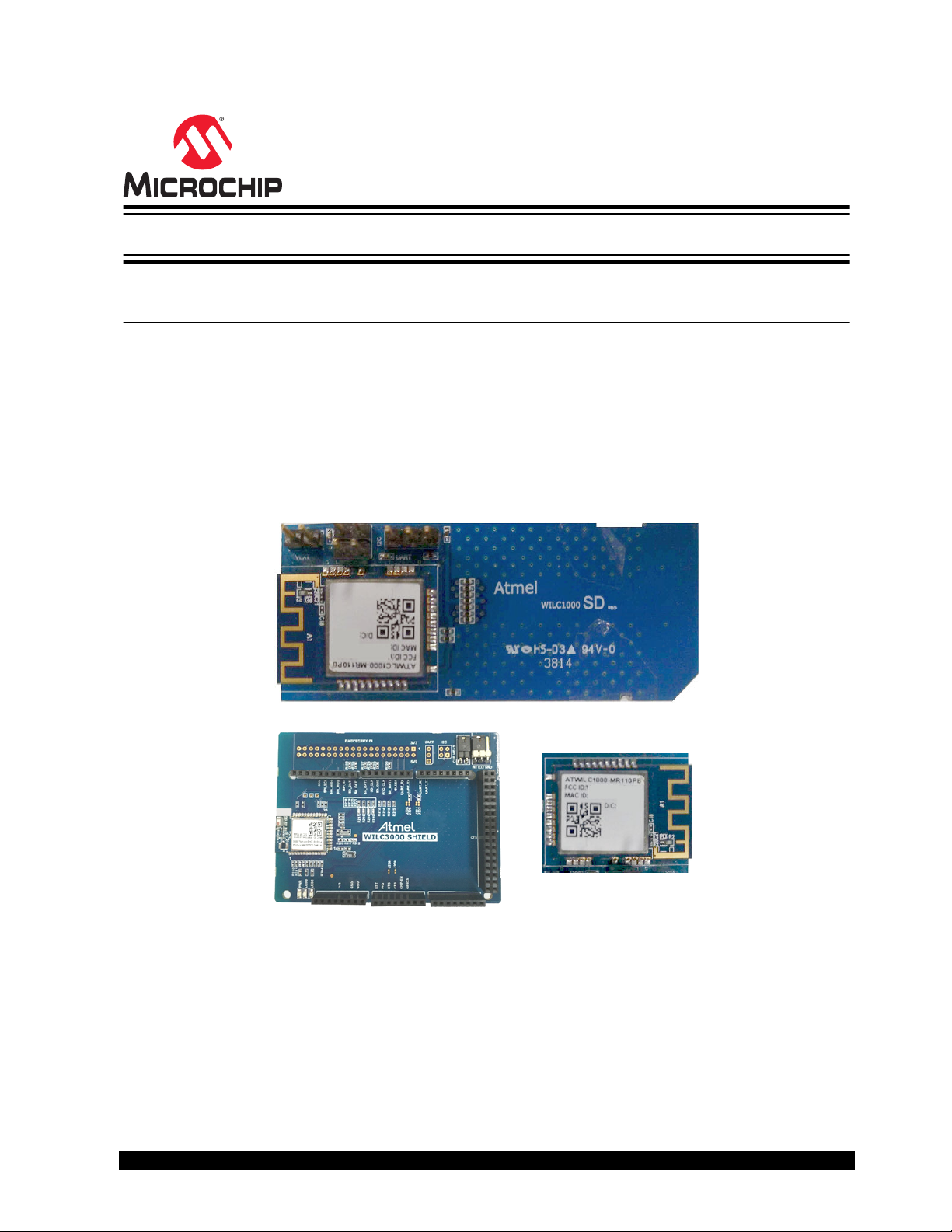
Figure 1. ATWILC1000 SD Card and ATWILC3000 Shield Board
© 2019 Microchip Technology Inc.
User Guide
DS70005328C-page 1
Page 2

ATWILC1000/ATWILC3000
Table of Contents
Introduction......................................................................................................................1
1. Prerequisites..............................................................................................................4
2. Building Linux for SAMA5D4 Xplained Ultra Board...................................................5
2.1. Cloning a Kernel Source and Root File System........................................................................... 5
2.2. Loading SAMA5D4 Configuration File..........................................................................................5
2.3. Buildroot File System and Linux Kernel....................................................................................... 5
2.4. Building Linux Kernel Individually.................................................................................................6
3. Building Linux for SAMA5D2 Xplained Ultra Board...................................................7
3.1. Cloning and Building Binaries...................................................................................................... 7
3.2. Creating an Image for SAMA5D2_Xplained to Boot using eMMC............................................... 9
3.3. Install the Demo Image on the SAMA5D2 Xplained eMMC....................................................... 11
4. Building and Flashing the System Image into the SAMA5D3 Xplained Board........13
5. Building and Flashing the System Image into the SAMA5D27-SOM1-EK1............ 15
5.1. Building the Components........................................................................................................... 15
5.2. Building Kernel........................................................................................................................... 16
6. Updating Binary and System Image into the Target Board......................................19
7. Updating ATWILC Firmware.................................................................................... 21
7.1. ATWILC1000 and ATWILC3000 Driver Modules........................................................................21
7.2. ATWILC1000 and ATWILC3000 Firmware Binaries...................................................................21
8. Running ATWILC..................................................................................................... 22
8.1. Accessing the Console...............................................................................................................22
8.2. Recognizing ATWILC1000......................................................................................................... 23
8.3. Recognizing ATWILC3000......................................................................................................... 24
8.4. Modifying Configuration Files..................................................................................................... 27
8.5. Running in the ATWILC Station Mode........................................................................................29
8.6. Running in the ATWILC AP Mode..............................................................................................31
8.7. Running in the ATWILC P2P Mode............................................................................................32
8.8. Supported Modes with Concurrency.......................................................................................... 34
8.9. Powersave .................................................................................................................................35
8.10. Antenna Switching......................................................................................................................37
8.11. Debug Logs ...............................................................................................................................38
8.12. Monitor Mode............................................................................................................................. 39
8.13. Miscellaneous Linux Topics........................................................................................................39
8.14. Running ATWILC3000 in Bluetooth Mode..................................................................................43
9. Document Revision History..................................................................................... 49
© 2019 Microchip Technology Inc.
User Guide
DS70005328C-page 2
Page 3

ATWILC1000/ATWILC3000
The Microchip Web Site................................................................................................ 50
Customer Change Notification Service..........................................................................50
Customer Support......................................................................................................... 50
Microchip Devices Code Protection Feature................................................................. 50
Legal Notice...................................................................................................................51
Trademarks................................................................................................................... 51
Quality Management System Certified by DNV.............................................................52
Worldwide Sales and Service........................................................................................53
© 2019 Microchip Technology Inc.
User Guide
DS70005328C-page 3
Page 4
1. Prerequisites
The build prerequisite for Linux is a host PC with Linux operating system. The hardware prerequisites are
the following:
• Linux
– SAMA5D4 Xplained Ultra
– ATWILC1000 SD Pro card
– ATWILC3000 Shield board
– USB to Serial adapter (for DEBUG port)
• Common
– Micro-USB cable (Micro-A/Micro-B)
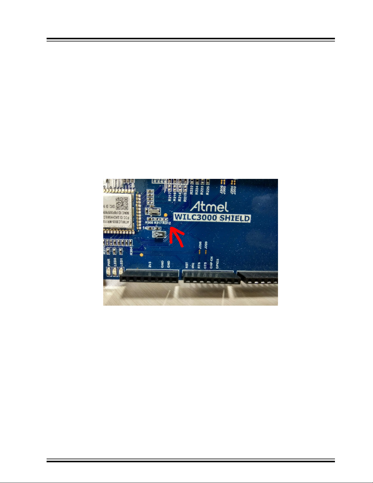
To avoid modifying kernel code, mount the resistor R312 with an approximate value of 120k Ohm in the
location shown below on the ATWILC3000 Shield board.
ATWILC1000/ATWILC3000
Prerequisites
© 2019 Microchip Technology Inc.
User Guide
DS70005328C-page 4
Page 5

ATWILC1000/ATWILC3000
Building Linux for SAMA5D4 Xplained Ultra ...
2. Building Linux for SAMA5D4 Xplained Ultra Board
This section describes how to build the root file system and kernel image to use for ATWILC devices
demo.
This user guide describes general information on the AT91Bootstrap and U-Boot information. For more
details on the AT91Bootstrap and U-Boot, see U-Boot of Linux & Open Source related information for
AT91 Smart ARM Microcontrollers.
2.1 Cloning a Kernel Source and Root File System
The demo uses buildroot to get the suitable toolchain, root file system, and Linux kernel.
The buildroot is cloned from linux4wilc github at the following address:
$ git clone https://github.com/linux4wilc/buildroot4wilc.git
The buildroot is cloned at the following path in the current directory:
\buildroot4wilc
The current buildroot4wilc is copied from buildroot's repository at git://git.buildroot.net/
buildroot, branch 2017_08, modified with WILC config files (configs/sama5_wilc_defconfig),
and other config files that help run WILC examples.
2.2 Loading SAMA5D4 Configuration File
Use the predefined defconfig file to create the required .config configuration file. This defconfig
file is available in configs folder of the buildroot folder buildroot4wilc.
For SAMA5D4, the sama5_wilc_defconfig defconfig file is used.
To build the root file system for SAMA5D4 with Linux kernel 4.9 for the ATWILC board, browse to the
directory where the files are extracted and create the .config file, using the following commands:
$ cd buildroot4wilc
$ make sama5_wilc_defconfig
2.3 Buildroot File System and Linux Kernel
Start the build operation using $ make command from the buildroot directory.
This $ make command displays the build status on the terminal.
Note: Ensure that the host PC is connected to the internet before starting the build operation and do not
use any build options.
The rootfs.ubi file is generated in the buildroot/output/images directory when the build
operation is complete. The default build will include the WILC modules in the rootfs.ubi.
The driver source files are located at: https://github.com/linux4wilc/linux-at91/tree/
master/drivers/staging/wilc1000 in the linux-at91 kernel.
Note: The driver directory name is wilc1000 for legacy reasons only. The driver supports both
ATWILC1000 and ATWILC3000.
© 2019 Microchip Technology Inc.
User Guide
DS70005328C-page 5
Page 6

2.4 Building Linux Kernel Individually
Buildroot downloads the Linux kernel as per the buildroot configuration file from GitHub. The downloaded
kernel must be available in the buildroot4wilc/output/build/linux-xxxx path, and is built
automatically during the buildroot build operation.
However, if the kernel is modified after building the buildroot, the user must rebuild the kernel. The
following is the procedure to build the Linux kernel against the toolchain and ARM architecture:
1. Change the directory to the Linux kernel source folder, using the following command:
$ cd output/build/linux-xx
2. Create the kernel with the help of sama5_defconfig defconfig file, using the following command:
$ make ARCH=arm sama5_defconfig
3. Perform the required changes using the menuconfig tool, using the following command:
$ make ARCH=arm menuconfig
4. Build the Linux kernel against the toolchain and ARM architecture, using the following commands:
$ make ARCH=arm CROSS_COMPILE=../../../output/host/opt/ext-toolchain/bin/arm-linuxgnueabihf$ make ARCH=arm CROSS_COMPILE=../../../output/host/opt/ext-toolchain/bin/arm-linuxgnueabihf- zImage
$ make ARCH=arm CROSS_COMPILE=../../../output/host/opt/ext-toolchain/bin/arm-linuxgnueabihf- dtbs
ATWILC1000/ATWILC3000
Building Linux for SAMA5D4 Xplained Ultra ...
© 2019 Microchip Technology Inc.
User Guide
DS70005328C-page 6
Page 7

ATWILC1000/ATWILC3000
Building Linux for SAMA5D2 Xplained Ultra ...
3. Building Linux for SAMA5D2 Xplained Ultra Board
This section describes how to build the bootstrap, U-Boot, Root File System (RFS), and Kernel image to
use for the ATWILC devices demo.
3.1 Cloning and Building Binaries
This section details how to clone and build the AT91Bootstrap, U-Boot, Kernel, and RFS.
3.1.1 AT91Bootstrap
Perform the following steps to build the AT91Bootstrap.
1. Clone the AT91Bootstrap from github at the following address:
$ git clone git://github.com/linux4sam/at91bootstrap.git
2. After the AT91Bootstrap download, enter in to the cloned directory using the following command:
$ cd at91bootstrap/
3. Build the bootstrap using the following commands:
Assuming that the user is at the AT91Bootstrap root directory, a board/sama5d2_xplained
folder is available which contains several default configuration files. The AT91Bootstrap is
configured and U-Boot binary is loaded from the embedded Multi-Media Controller (eMMC).
4. For the boot ROM code to recognize the valid boot code in the SD card or embedded Multi-Media
3.1.2 U-Boot
Perform the following steps to build the u-boot.
Note: Make sure to install the mkenvimage tool on the Linux machine.
1. Clone the u-boot from github at the following address:
2. After the AT91Bootstrap download, enter in to the cloned directory using the following command:
3. Switch to a new branch u-boot-2018.07-at91, using the following commands:
$make mrproper
make ARCH=arm CROSS_COMPILE=arm-linux-gnueabihf- sama5d2_xplainedemmc_uboot_defconfig
Note: Make sure that the path of the toolchain is exported to PATH environment variable.
This generates the sama5d2_xplained-sdcardboot-uboot-3.8.12.bin binary which is
located in the binary folder.
Controller (eMMC) , rename the sama5d2_xplained-sdcardboot-uboot-3.8.12.bin
AT91bootstrap file to BOOT.bin.
$ git clone git://github.com/linux4sam/u-boot-at91.git
$ cd u-boot-at91
$git branch -r
$ git checkout origin/u-boot-2018.07-at91 -b u-boot-2018.07-at91
4. Apply the configuration file (sama5d2_xplained_mmc_defconfig) to u-boot, using the following
command:
$make ARCH=arm CROSS_COMPILE=arm-linux-gnueabihf- sama5d2_xplained_mmc_defconfig
© 2019 Microchip Technology Inc.
User Guide
DS70005328C-page 7
Page 8

ATWILC1000/ATWILC3000
Building Linux for SAMA5D2 Xplained Ultra ...
5. Open the u-boot-at91/include/configs/sama5d2_xplained.h file and modify the
definitions for FAT_ENV_DEVICE_AND_PART and CONFIG_BOOTCOMMAND, using the following
commands:
/*bootstrap + u-boot + env in sd card */
#undef FAT_ENV_DEVICE_AND_PART
#undef CONFIG_BOOTCOMMAND
#define FAT_ENV_DEVICE_AND_PART "0"
#define CONFIG_BOOTCOMMAND "fatload mmc 0:1 0x21000000 at91-sama5d2_xplained.dtb; " \
"fatload mmc 0:1 0x22000000 zImage; " \
"bootz 0x22000000 - 0x21000000"
#undef CONFIG_BOOTARGS
#define CONFIG_BOOTARGS \
"console=ttyS0,115200 earlyprintk root=/dev/mmcblk0p2 rw rootwait"
6. Build the u-boot binary, using the following command:
$make ARCH=arm CROSS_COMPILE=arm-linux-gnueabihf-
The u-boot.bin output is built in the root folder (u-boot-at91 folder).
Note: Make sure that the cross compiler toolchain is available in the same path.
7. Create a text file u-boot-env.txt in a directory, such as home folder with the u-boot
environment variables and copy the following to the file:
bootargs=console=ttyS0,115200 root=/dev/mmcblk0p2 rw rootfstype=ext4 rootwait
bootcmd=fatload mmc 0:1 0x21000000 at91-sama5d2_xplained.dtb; fatload mmc 0:1 0x22000000
zImage; bootz 0x22000000 - 0x21000000
bootdelay=1
ethact=gmac0
stderr=serial
stdin=serial
stdout=serial
8. Move to the main folder and enter the following command to generate uboot.env file.
3.1.3 Kernel
Perform the following steps to build the kernel.
1. Clone the repository to get the source code, using the following command:
2. To use another branch, list the branches and use one of them by using the following commands:
3. Replace the ATWILC1000 driver in drivers/staging/wilc with the content for the driver/
4. Modify the following line in linux-at91/drivers/staging/Makefile so that the build finds
$ mkenvimage -s 0x2000 -o uboot.env u-boot-env.txt
git clone git://github.com/linux4sam/linux-at91.git
git branch -r
git checkout origin/linux-4.14-at91 -b linux-4.14-at91
wilc directory on the ATWILC driver repository. The repository is available at: https://github.com/
linux4wilc.
Enter the following command to get the files from linux4wilc:
git clone git://github.com/linux4wilc/driver
the correct directory:
FROM: obj-$(CONFIG_WILC1000) += wilc1000/
TO: obj-$(CONFIG_WILC) += wilc1000/
5. Configure the kernel using the following command:
make ARCH=arm CROSS_COMPILE=arm-linux-gnueabihf- sama5_defconfig
© 2019 Microchip Technology Inc.
User Guide
DS70005328C-page 8
Page 9

ATWILC1000/ATWILC3000
Building Linux for SAMA5D2 Xplained Ultra ...
6. Modify the default configuration using the menuconfig. Perform the following to open the
menuconfig:
– make ARCH=arm CROSS_COMPILE=arm-linux-gnueabihf- menuconfig
– Select the ATWILC driver module, using the following steps:
1. Go to menuconfig.
2. Navigate to Device Drivers>Staging driver.
3. Press 'y' to include Staging Drivers.
4. Select either Atmel WILC SDIO or Atmel WILC SPI based on the requirement.
5. Press 'M' to select the WILC SDIO or WILC SPI.
6. Save the configuration.
Make sure the mmc1 node of arch/arm/boot/dts/at91-sama5d2_xplained.dts file is
similar to the following node.
mmc1: mmc@fc000000 {
pinctrl-names = "default";
pinctrl-0 = <&pinctrl_mmc1_clk_cmd_dat0 &pinctrl_mmc1_dat1_3 &pinctrl_mmc1_cd>;
vmmc-supply = <&vcc_mmc1_reg>;
vqmmc-supply = <&vcc_3v3_reg>;
non-removable;
status = "okay";
slot@0 {
reg = <0>;
bus-width = <4>;
};
};
7. Build the kernel, using the following command:
$ make ARCH=arm CROSS_COMPILE=arm-linux-gnueabihf- zImage
8. Build the .dtb file, using the following command:
$ make ARCH=arm CROSS_COMPILE=arm-linux-gnueabihf- at91-sama5d2_xplained.dtb
9. Build the modules, using the following command:
$ make ARCH=arm CROSS_COMPILE=arm-linux-gnueabihf- modules
When the building process is successful, the final kernel image is available in arch/arm/boot/
directory and the at91-sama5d2_xplained.dtb file is available in arch/arm/boot/dts folder.
3.1.4 Root File System
Use the build root to build the rootfs. For more information, see Building rootfs for SAMA5D2 Xplained
Pro Board.
3.2 Creating an Image for SAMA5D2_Xplained to Boot using eMMC
A single bootable image is required to write on eMMC of the SAMA5D2 Xplained target. This image must
contain all the images (AT91bootstrap, u-boot, kernel and rootfs) built (Cloning and Building Binaries). To
create the image, perform the following steps.
1. Create a directory called junk under home directory. Create a dummy image file sdcard.img,
using the following command:
$sudo dd if=/dev/zero of=~/junk/sdcard.img bs=2G count=1
$ls -al
© 2019 Microchip Technology Inc.
User Guide
DS70005328C-page 9
Page 10

ATWILC1000/ATWILC3000
Building Linux for SAMA5D2 Xplained Ultra ...
2. >Move to the junk directory and partition the image file with two partitions, using the following
commands:
$sudo fdisk sdcard.img
Welcome to fdisk(util-linux 2.27.1).
Changes will remain in memory only, until you decide to write them.
Be careful before using the write command.
Device does not contain a recognized partition table.
Created a new DOS disklabel with disk identifier 0x24d68b30.
Command (m for help): n
Partion type
p primary (0 primary, 0 extended, 4 free)
e extended (container for logical partions)
Select (default p): p
Partition number (1-4, default 1):
First sector (2048-4194295, default 2048):
Last sector, +sectors or +size{K,M,G,T,P} (2048-4194295, default 4194295):+64M
Created a new partition 1 of type 'Linux' and of size 64 MiB.
Command (m for help): t
Selected partion 1
Partition type (type L to list all types): b
Changed type of partition 'Linux' to 'W95 FAT32'.
Command (m for help): n
Partion type
p primary (1 primary, 0 extended, 3 free)
e extended (container for logical partitions)
Select (default p):
Using default response p.
Partition number (2-4, default 2):
First sector (133120-4194295, default 133120):
Last sector, +sectors or +size{K,M,G,T,P} (133120-4194295, default4194295):
Created a new partition 2 of type 'Linux' and of size 2 GiB.
Command (m for help): w
The partition table has been altered.
Syncing disks.
Two partitions in sdcard.img file are created successfully.
3. Mount the two partitions on two loop devices, using the following commands:
$sudo losetup /dev/loop0 sdcard.img -o 1048576
$sudo losetup /dev/loop1 sdcard.img -o 68157440
Note: The numbers 1048576 and 68157440 are the offsets of the partitions.
This partition can be verified using the following command:
fdisk -l sdcard.img
Disk linux4sam-yocto-sama5d2_xplained.img: 2 GiB, 2147479552 bytes, 4194296sectors
Units: sectors of 1 * 512 = 512 bytes
Sector size (logical/physical): 512 bytes / 512 bytes
I/O size (minimum/optimal): 512 bytes / 512 bytes
Disklabel type: dos
Disk identifier: 0x24d68b30
Device Boot Start End Sectors Size Id Type
linux4sam-yocto-sama5d2_xplained.img1 2048 133119 131072 64M b W95 FAT
linux4sam-yocto-sama5d2_xplained.img2 133120 4194295 4061176 2G 83 Linux
Here, the first partition starts at “2048” location and its physical location is (512 bytes * 2048)
1048576.
© 2019 Microchip Technology Inc.
User Guide
DS70005328C-page 10
Page 11

ATWILC1000/ATWILC3000
Building Linux for SAMA5D2 Xplained Ultra ...
Similarly, the second partition starts at “133120” location and its physical location is (512 bytes *
133120) 68157440.
4. Format the partitions that are mounted on the loop devices, using the following commands:
$sudo mkfs.vfat /dev/loop0
$sudo mkfs.ext4 /dev/loop1
5. Create two temporary folders and mount each partition (FAT32 and EXT4) on the folders, using the
following commands:
$ mkdir emmcmntp1
$ mkdir emmcmntp2
$ sudo mount -o loop,offset=1048576 sdcard.img emmcmntp1
$ sudo mount -o loop,offset=68157440 sdcard.img emmcmntp2
6. In the first partition (FAT32), copy the AT91bootstrap, u-boot, uboot.env, kernel and dtb files, using
the following commands:
$ cd emmcmntp1
$ sudo cp <path>at91bootstrap/binaries/BOOT.bin .
$ sudo cp <path>u-boot-at91/u-boot.bin .
$ sudo cp <path>uboot.env .
$ sudo cp <path>linux-at91/arch/arm/boot/zImage .
$ sudo cp <path>linux-at91/arch/arm/boot/dts/at91-sama5d2_xplained.dtb .
7. In the second partition (EXT4), copy the rootfs , using the following commands:
$ cd ../emmcmntp2
$ sudo tar -zxvf <path> <path to the newly build rootfs tar file>
eg: core-image-minimal-sama5d2-xplained-20181114120437.rootfs.tar.gz
8. Unmount the temporary mount points emmcmntp1, emmcmntp2, and loop device using the
following commands:
$ cd ..
$ sudo umount emmcmntp1 emmcmntp2
$ sudo losetup -d/dev/loop0
$ sudo losetup -d/dev/loop1
3.3 Install the Demo Image on the SAMA5D2 Xplained eMMC
Prerequisite:
• Connect the FTDI cable to the Debug connector (J1).
Note: Do not use J14 connector to receive debug messages.
• Download the SAM-BA
1. Add the path to SAM-BA in your ~.bashrc file.
2. Connect a USB cable to J23 port to flash the image.
3. Close the jumper JP9, press the reset button and open the jumper.
4. Create a qml file emmc-usb.qml and add the following:
import SAMBA 3.2
import SAMBA.Connection.Serial 3.2
import SAMBA.Device.SAMA5D2 3.2
SerialConnection {
//port: "ttyACM0"
//port: "COM85"
//baudRate: 57600
device: SAMA5D2Xplained {
}
onConnectionOpened: {
// initialize SD/MMC applet
®
3.2.1 for Linux software from the SAM-BA In-system Programmer.
© 2019 Microchip Technology Inc.
User Guide
DS70005328C-page 11
Page 12

ATWILC1000/ATWILC3000
Building Linux for SAMA5D2 Xplained Ultra ...
initializeApplet("sdmmc")
// write file
applet.write(0, "sdcard.img", false)
// initialize boot config applet
initializeApplet("bootconfig")
// Use BUREG0 as boot configuration word
applet.writeBootCfg(BootCfg.BSCR, BSCR.fromText("VALID,BUREG0"))
// Enable external boot only on SDMMC0
applet.writeBootCfg(BootCfg.BUREG0,
BCW.fromText("EXT_MEM_BOOT,UART1_IOSET1,JTAG_IOSET1," +
"SDMMC0,SDMMC1_DISABLED,NFC_DISABLED," +
"SPI1_DISABLED,SPI0_DISABLED," +
"QSPI1_DISABLED,QSPI0_DISABLED"))
}
}
5. Run the .qml script, using the following command:
$sudo su
$ <path>sam-ba -x emmc-usb.qml
Note: This process takes several minutes to complete.
The sdcard.img is installed on the SAMA5D2 Xplained eMMC.
When the flashing is complete, debug messages are sent via J1 port.
© 2019 Microchip Technology Inc.
User Guide
DS70005328C-page 12
Page 13

ATWILC1000/ATWILC3000
Building and Flashing the System Image into ...
4. Building and Flashing the System Image into the SAMA5D3 Xplained Board
Perform the following steps to build and Flash the system image in to the SAMA5D3 Xplained board.
1. Download the default demo package linux4sam-poky-sama5d3_xplained-6.0.zip from
https://www.at91.com/linux4sam/bin/view/Linux4SAM/Sama5d3XplainedMainPage.
2. Download the Linux kernel 4.4.87 from https://www.kernel.org/.
3. Replace the existing WILC1000 driver directory from drivers/staging/wilc1000 directory with
the ATWILC driver available in www.github.com/linux4wilc/.
4. Modify the CONFIG_WILC1000 macro to CONFIG_WILC in the Makfile. This file is available in
drivers/staging/Makfile location.
5. Download the firmware binaries from https://github.com/linux4wilc/firmware and update the existing
firmware files in /firmware/mchp/ of the kernel directory.
6. Configure the kernel using the command make ARCH=arm sama5_defconfig.
7. Open the menuconfig using the command make ARCH=arm menucofig.
8. Select the ATWILC driver module, using the following steps:
8.1. Go to menuconfig.
8.2. Navigate to Device Drivers > Staging driver.
8.3. Select either Atmel WILC SDIO or Atmel WILC SPI based on the requirement.
Note: Ensure that the mmc1 node of arch/arm/boot/dts/at91-sama5d3_xplained.dts file
is similar to the node with the following:
mmc1: mmc@fc000000 {
pinctrl-names = "default";
pinctrl-0 = <&pinctrl_mmc1_clk_cmd_dat0 &pinctrl_mmc1_dat1_3 &pinctrl_mmc1_cd>;
vmmc-supply = <&vcc_mmc1_reg>;
vqmmc-supply = <&vcc_3v3_reg>;
non-removable;
status = "okay";
slot@0
{ reg = <0>; bus-width = <4>; };
};
9. Save the .config file.
10. Build the kernel using the following command:
make ARCH=arm CROSS_COMPILE=arm-linux-gnueabi
11. Build the modules using the following command:
make ARCH=arm CROSS_COMPILE=arm-linux-gnueabi modules
12. Build the zImage using the following command:
make ARCH=arm CROSS_COMPILE=arm-linux-gnueabi zImage
13. Build the dtb file using the following command:
make ARCH=arm CROSS_COMPILE=arm-linux-gnueabi at91-sama5d2_xplained.dtb
The ATWILC driver modules are built under /drivers/staging/wilc1000.
The wilc.ko, wilc-sdio.ko, and wilc-spi.ko modules are common for ATWILC1000 and
ATWILC3000.
14. Download the SAM-BA tool version SAM-BA 2.16 for Linux software from SAM-BA In-system
Programmer.
© 2019 Microchip Technology Inc.
User Guide
DS70005328C-page 13
Page 14

ATWILC1000/ATWILC3000
Building and Flashing the System Image into ...
15. Export the path of the SAM-BA binary to the PATH environment variable.
16. Copy the zImage and at91-sama5d3_xplained.dtb files in to the demo package
linux4sam-poky-sama5d3_xplained-5.6.
17. Rename the zImage file to zImage-sama5d3-xplained.bin in the demo package.
18. Connect the Micro USB cable to the EDBG-USB connector (J6) of the ATSAMA5D3 board.
19. Connect the FTDI cable to the DEBUG connector (J23) of the ATSAMA5D3 board to receive the
debug messages.
20. Open /dev/ttyUSB0 with minicom. Set the baudrate as 115200.
21. Open the jumper jp5. Press Reset button. A log message "RomBOOT" is sent to minicom.
22. Short the jumper (jp5) and run the demo_linux_nandflash.sh script to flash the binaries.
23. When the booting is complete, copy the wilc.ko.wilc-sdio.ko, and wilc-spi.ko to the
rootfile system using mass storage drive.
24. Copy and replace the existing firmware files from http://www.github.com/linux4wilc/.
25. Run the wilc.ko and wilc-sdio.ko modules. When successful, wlan0 interface is up and
running.
© 2019 Microchip Technology Inc.
User Guide
DS70005328C-page 14
Page 15

ATWILC1000/ATWILC3000
Building and Flashing the System Image into the SA...
5. Building and Flashing the System Image into the SAMA5D27-SOM1EK1
This section provides the instructions to build the components for running Linux on the SAMA5D27SOM1-EK1 board. This setup is configured to boot from the micro-SD card slot which leaves the standard
SD card slot open for the ATWILC1000 SDIO board.
Note: Since the reset and chip-enable signals are not brought across the SDIO connector to the
ATWILC1000 module, the SDIO board must be power cycled to reset it in the case of a system reset. If
this is not done then repeated errors will be displayed at the Linux prompt until the card is removed and
re-inserted. This behavior can be seen on a reset via NRST on the board or via a Linux reboot command.
The workaround for the demo board is to remove and re-insert the card. In a client application the reset
and chip enable signals to the ATWILC1000 must be controlled via I/O pins.
If the building process is successful, the final images can be found under the arch/arm/boot/
directory.
5.1 Building the Components
This section provides the procedure to build Bootstrap and U-Boot.
5.1.1 Bootstrap
This section provides the procedure to get source code from the git repository, configure with the default
configuration, customize the AT91Bootstrap based on the default configuration, and build the
AT91Bootstrap to generate the binary.
1. Clone the repository to get the source code, using the following commands:
git clone git://github.com/linux4sam/at91bootstrap.git
cd at91bootstrap/
2. Configure the AT91Bootstrap. It is assumed that the user is at AT91Bootstrap root directory,
board/sama5d27_som1_ek folder which contains several default configuration files:
Configure the AT91Bootstrap to load U-boot binary from SD card.
$ make mrproper
$ make ARCH=arm CROSS_COMPILE=arm-linux-gnueabihf-ama5d27_som1_eksd_uboot_defconfig
If the configuring process is successful, the .config file can be found at AT91Bootstrap root
directory.
3. Customize the AT91Bootstrap using the menuconfig.
Enter the following command and select SDHC1 as the SD card interface rather than the default
SDHC0.
make ARCH=arm CROSS_COMPILE=arm-linux-gnueabihf- menuconfig
4. Build the AT91Bootstrap using the following command:
make ARCH=arm CROSS_COMPILE=arm-linux-gnueabihf-
5.1.2 U-Boot
Perform the following steps to build the U-boot.
© 2019 Microchip Technology Inc.
On successful building process, the final .bin image can be found in binaries/
at91bootstrap.bin folder.
User Guide
DS70005328C-page 15
Page 16

ATWILC1000/ATWILC3000
Building and Flashing the System Image into the SA...
1. Get the SAMA5D2 default u-boot code by cloning the Linux4sam GitHub U-Boot repository, using
the following commands:
git clone git://github.com/linux4sam/u-boot-at91.git
cd u-boot-at91
2. The source code is fetched from the master branch which leads to the latest branch. If the user
wants to use the other branch, the user can list them and use one of branches by using the
following commands:
git branch -r
git checkout origin/u-boot-2018.07-at91 -b u-boot-2018.07-at91
3. Compile the u-boot. The U-Boot environment variables can be stored in different media, the config
files specifies where to store the U-Boot environment. Use the following command to add the
environment variables in SD/MMC card:
make ARCH=arm CROSS_COMPILE=arm-linux-gnueabihf- sama5d27_som1_ek_mmc1_defconfi
4. Build the U-boot, using the following command:
make ARCH=arm CROSS_COMPILE=arm-linux-gnueabihf-
The U-boot binary u-boot.bin file is generated.
5.2 Building Kernel
Perform the following steps to build the kernel.
1. Clone the repository to get the source code, using the following commands:
git clone git://github.com/linux4sam/linux-at91.git
2. To use another branch, list the branches and use one of them by using the following commands:
git branch -r
git checkout origin/linux-4.14-at91 -b linux-4.14-at91
3. Replace the ATWILC1000 driver in drivers/staging/wilc with the content for the driver/
wilc directory on the ATWILC driver repository. The repository is available at: https://github.com/
linux4wilc.
Enter the following command to get the files from linux4wilc:
git clone git://github.com/linux4wilc/driver
4. Modify the following line in linux-at91/drivers/staging/Makefile so that the build finds
the correct directory:
FROM: obj-$(CONFIG_WILC1000) += wilc1000/
TO: obj-$(CONFIG_WILC) += wilc1000/
5. Configure the kernel using the following command:
make ARCH=arm CROSS_COMPILE=arm-linux-gnueabihf- sama5_defconfig
6. Modify the default configuration using the menuconfig. Perform the following to open the
menuconfig:
– make ARCH=arm CROSS_COMPILE=arm-linux-gnueabihf- menucofig
– Select the ATWILC driver module, using the following steps:
1. Go to menuconfig.
2. Navigate to Device Drivers>Staging driver.
© 2019 Microchip Technology Inc.
User Guide
DS70005328C-page 16
Page 17
ATWILC1000/ATWILC3000
Building and Flashing the System Image into the SA...
3. Press 'y' to include Staging Drivers.
4. Select either Atmel WILC SDIO or Atmel WILC SPI based on the requirement.
5. Press 'M' to select the WILC SDIO or WILC SPI.
6. Save the configuration.
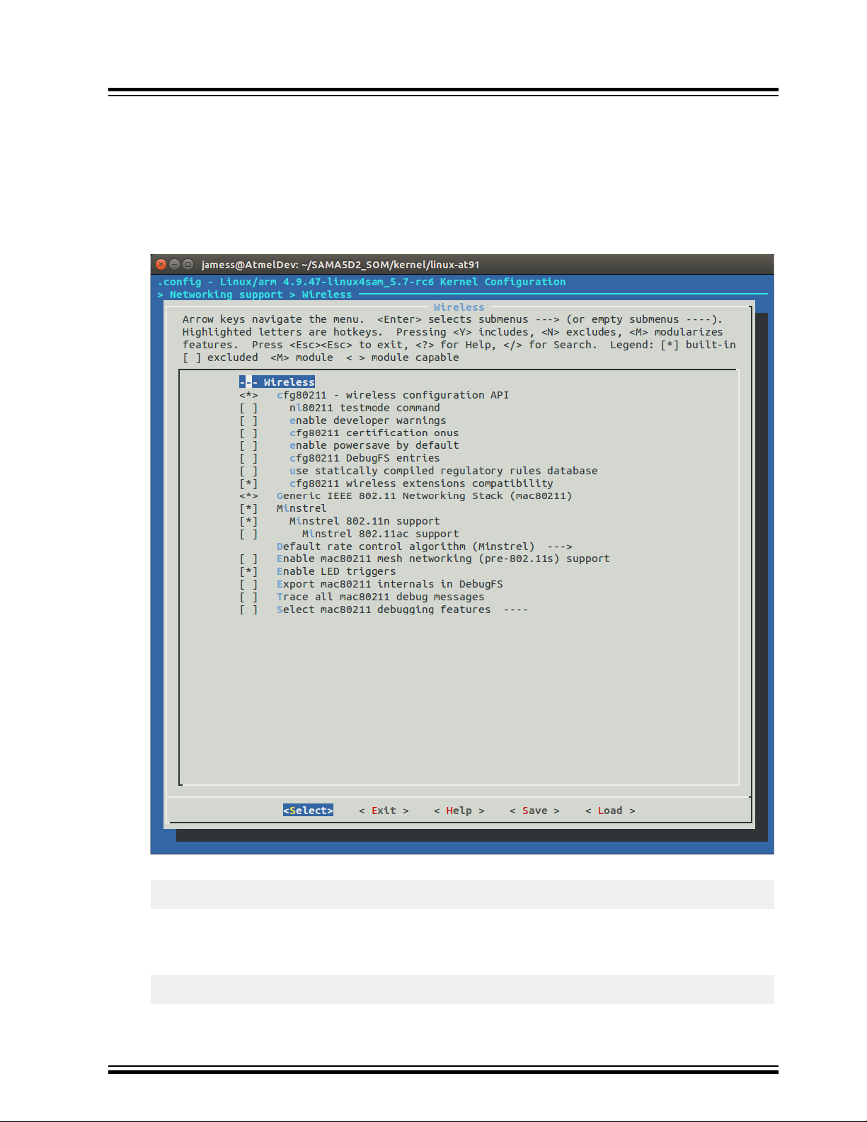
7. Choose Networking Support>Wireless as shown in the following screenshot:
Note: Ensure that all configurations are done as shown in the following screenshot.
Figure 5-1. Networking Support Menuconfig Window
8. Build the kernel using the following command:
make ARCH=arm CROSS_COMPILE=arm-linux-gnueabihf-z Image
If the building process is successful, the final images can be found under arch/arm/boot/
directory.
9. Build the modules using the following command:
make ARCH=arm CROSS_COMPILE=arm-linux-gnueabi modules
© 2019 Microchip Technology Inc.
User Guide
DS70005328C-page 17
Page 18

ATWILC1000/ATWILC3000
Building and Flashing the System Image into the SA...
10. Build the dtb file using the following command:
make ARCH=arm CROSS_COMPILE=arm-linux-gnueabi at91-sama5d2_xplained.dtb
© 2019 Microchip Technology Inc.
User Guide
DS70005328C-page 18
Page 19

ATWILC1000/ATWILC3000
Updating Binary and System Image into the ...
6. Updating Binary and System Image into the Target Board
This section describes how to update or flash the system image. The pre-build images include pre-build
driver and firmware binaries, which are available at GitHub.
The SAM-BA® tool is used to flash the binaries into the target board.
Note: Ensure that the SAM-BA tool is installed in the host machine before updating the system image.
The scripts in the demo package can use either SAM-BA 2.16 or 3.2.x depending on the download script
the user selects in step 5 of the following procedure.
For additional information, refer to the following:
• Software Tools
• SAMA5D4 Xplained Board
• ATSAMA5D44 Microprocessor
To start flashing, perform the following steps:
1. Download the pre-built images from https://github.com/linux4wilc/wilc_demo.
2. Unzip the downloaded file.
3. Once the new image is built as described in Chapter 2, Building Linux for SAMA5D4 Xplained Ultra
Board, these files must be copied from the buildroot\output\images directory to the directory
where the demo_linux_nandflash.tcl file is available.
Figure 6-1. List of Files in buildroot\output\images Location
4. Add the jumper at JP7 and connect to the host PC via the USB port at J11. Ensure that the host
machine completes the USB serial port connection and then remove the jumper at JP7. The
following figure shows the SAMA5D4 adapter connections.
© 2019 Microchip Technology Inc.
User Guide
DS70005328C-page 19
Page 20

Updating Binary and System Image into the ...
Figure 6-2. SAMA5D4 Adapter Connections
ATWILC1000/ATWILC3000
5. Execute the demo_linux_nandflash.bat (for Windows®) file or the
demo_linux_nandflash.sh (for Linux) file.
Note:
• By default, the demo_linux_nandflash.sh file has sam-ba binary for 32-bit operating
system. For 64-bit operating system, change the sam-ba to sam-ba_64 in the same file.
• Execute the script in the super user mode. If sam-ba 3.2 is installed, use
demo_linux_nandflash_3_2.bat or demo_linux_nandflash_3_2.sh instead.
The output log can be viewed via J1 serial port.
Open the serial terminal on PC via the COM port, with the following configurations:
• 115200 baud rate
• 8-bit data
• No parity
• One stop bit
• No flow control
6. Successful download of the system image into the board is indicated by a log file, which opens
automatically. This log file contains all the download process history.
© 2019 Microchip Technology Inc.
User Guide
DS70005328C-page 20
Page 21

ATWILC1000/ATWILC3000
7. Updating ATWILC Firmware
This chapter describes how to update the ATWILC firmware or driver on the demo image.
7.1 ATWILC1000 and ATWILC3000 Driver Modules
After the system boots, add the ATWILC driver modules wilc-sdio.ko, or wilc-spi.ko to /lib/
modules/4.9.xx-XX/kernel/drivers/staging/wilc1000/ directory or copy to any location on
the file system.
7.2 ATWILC1000 and ATWILC3000 Firmware Binaries
1. Add the ATWILC1000 firmware wilc1000_wifi_firmware.bin to the /lib/firmware/
mchp/ directory.
2. Add the ATWILC3000 Wi-Fi firmware, wilc3000_wifi_firmware.bin to the/lib/firmware/
mchp/ directory.
3. Add the ATWILC3000 Bluetooth® firmware, wilc3000_ble_firmware.bin to the /lib/
firmware/mchp/ directory.
Updating ATWILC Firmware
Note: The firmware is available at https://github.com/linux4wilc/firmware.
The files can be transferred into the SAMA5D4 platform using any of the following methods:
• Ethernet
• ZMODEM
7.2.1 Adding Files Using Ethernet
The Local Area Network (LAN)/ Wide Area Network (WAN) can be used to transfer the file from one
machine to another machine, using the following command:
$ scp [path of file to send] root@[receiver's IP]:[target directory]
For example, the following command sends the wilc1000_wifi_firmware.bin file from the binary
directory to the /lib/firmware/mchp directory of the device using the internal IP address
192.168.0.11.
$ scp binary/wilc1000_wifi_firmware.bin root@192.168.0.11:/lib/firmware/mchp
7.2.2 Adding Files using ZMODEM
The ZMODEM file transfer protocol also can be used to transfer the files.
In Teraterm, change the target location directory using the following command:
$ cd Target_location
Execute the ZMODEM command using the following command:
$ rz
In Teraterm, from the File menu, choose Transfer > Send, then browse and select the desired file.
© 2019 Microchip Technology Inc.
User Guide
DS70005328C-page 21
Page 22

8. Running ATWILC
This chapter describes how to use the ATWILC1000 and ATWILC3000 on the SAMA5D4 Xplained Board
or any similar Linux platform.
8.1 Accessing the Console
The user can access the serial console through the on board serial-to-USB converter. In fact, the
Embedded Debugger (EDBG) chip on the evaluation kit acts as a serial-to-USB converter and is loaded
with a firmware that can communicate via USB-CDC protocol.
To enable EDBG, open JP1 and connect the USB cable to the board (J20 EDBG-USB).
8.1.1 For Microsoft Windows Users
Install USB drivers for Atmel and Segger tools. Then, identify the USB connection that is established. The
user can verify this by checking if the EDBG virtual COM port appears in the Device Manager. The
COMxx number is used to configure the terminal emulator.
8.1.2 For Linux Users
Identify the USB connection by monitoring the last lines of dmesg command. The /dev/ttyACMx
number is used to configure the terminal emulator.
ATWILC1000/ATWILC3000
Running ATWILC
The following is the USB debug port connection:
[172677.700868] usb 2-1.4.4: new full-speed USB device number 31 using ehci-pci
[172677.792677] usb 2-1.4.4: not running at top speed; connect to a high speed hub
[172677.793418] usb 2-1.4.4: New USB device found, idVendor=03eb, idProduct=6124
[172677.793424] usb 2-1.4.4: New USB device strings: Mfr=0, Product=0, SerialNumber=0
[172677.793897] cdc_acm 2-1.4.4:1.0: This device cannot do calls on its own. It is not a
modem.
[172677.793924] cdc_acm 2-1.4.4:1.0: ttyACM0: USB ACM device
The identifiers idVendor=03eb, and idProduct=6124 indicate the device as the evaluation kit board with
USB connection.
Now, use the terminal emulator with appropriate terminal settings (see Table 8-1) to communicate with
the SAMA5D4 adapter.
8.1.3 Serial Communication Parameters
The serial communication parameters are as follows:
Table 8-1. Serial Port Settings
Function Settings
Baud rate 115200
Data 8-bit
Parity None
Stop 1-bit
Flow control None
© 2019 Microchip Technology Inc.
User Guide
DS70005328C-page 22
Page 23

8.2 Recognizing ATWILC1000
The following section describes the SD express board and Serial Peripheral Interface (SPI) board
connections.
8.2.1 SD Express Board
Before performing the boot-up operation, ensure that the ATWILC1000 SD Express board is connected in
the SD slot (J24) of the SAMA5D4 Xplained board (see following figure).
Figure 8-1. SAMA5D4 SD Connection
ATWILC1000/ATWILC3000
Running ATWILC
The Secure Digital Input/Output (SDIO) Express card is recognized during boot-up with the following
lines.
mmc0: new high speed SDIO card at address 0001
Use the following commands to load the ATWILC1000 module SDIO driver.
Welcome to Buildroot
buildroot login: root
[root@buildroot ~]# insmod wilc.ko
wilc: module is from the staging directory, the quality is unknown, you have been warned.
[root@buildroot ~]# insmod wilc-sdio.ko
wilc_sdio: module is from the staging directory, the quality is unknown, you have been
warned.
linux_sdio_probe init_power =0
wilc_sdio mmc0:0001:1:Driver Initializing success
Note: Do not panic upon receiving the following message while loading the module:
wilc: module is from the staging directory, the quality is unknown, you have
been warned
This is the default message for all the drivers in kernel staging directory.
© 2019 Microchip Technology Inc.
User Guide
DS70005328C-page 23
Page 24

8.2.2 Serial Peripheral Interface Board
The ATWILC1000 Serial Peripheral Interface (SPI) board must be connected to SPI1 interface at J17 as
shown in the following figure.
Figure 8-2. SAMA5D4 SPI Connection
ATWILC1000/ATWILC3000
Running ATWILC
Table 8-2. SPI Pin Descriptions
SPI Pins Header J17 Pins XPRO EXT1 Pins
MOSI PIN11 PIN16
CLK PIN13 PIN18 (SPCK)
MISO PIN12 PIN17
CS PIN10 PIN15
IRQ PIN8 PIN9
Note: VEXT pin in the SPI card can be connected to 3V3 pin in the header J6. Alternatively, WINC1500/
WINC3400 Xplained Pro boards can be directly connected to XPRO EXT1 header, which exposes the
same SPI1 peripheral exposed on J17. In this case, the IRQ GPIO has to be changed to PB26, which is
pin9 of XPRO EXT1.
8.3 Recognizing ATWILC3000
The following section describes the SDIO shield board and SPI shield board connections.
8.3.1 SDIO Shield Board
Before performing the bootup operation, ensure that the ATWILC3000 Shield board is connected to the
Shield Arduino Shield Stacking Connector of the SAMA5D4 Xplained adapter.
Load the Wi-Fi SDIO driver module using the following command:
# modprobe wilc-sdio
wilc_sdio: module is from the staging directory, the quality is unknown, you have been warned.
(unnamed net_device) (uninitialized): INFO [wilc_create_wiphy]Registering wifi device
(unnamed net_device) (uninitialized): INFO [wilc_wfi_cfg_alloc]Allocating wireless device
(unnamed net_device) (uninitialized): INFO [wilc_create_wiphy]Successful Registering
(unnamed net_device) (uninitialized): INFO [wilc_create_wiphy]Registering wifi device
(unnamed net_device) (uninitialized): INFO [wilc_wfi_cfg_alloc]Allocating wireless device
(unnamed net_device) (uninitialized): INFO [wilc_create_wiphy]Successful Registering
© 2019 Microchip Technology Inc.
User Guide
DS70005328C-page 24
Page 25

ATWILC1000/ATWILC3000
Running ATWILC
wilc_sdio mmc0:0001:1: WILC got 60 for gpio_reset
wilc_sdio mmc0:0001:1: WILC got 94 for gpio_chip_en
wilc_sdio mmc0:0001:1: WILC got 91 for gpio_irq
wifi_pm : 0
wifi_pm : 1
wilc_sdio mmc0:0001:1: Driver Initializing success
# wilc_sdio mmc0:0001:1 wlan0: INFO [wilc_netdev_cleanup]Unregistering netdev d4643800
wilc_sdio mmc0:0001:1 wlan0 (unregistered): INFO [wilc_netdev_cleanup]Freeing Wiphy...
wilc_sdio mmc0:0001:1 wlan0 (unregistered): INFO [wilc_free_wiphy]Unregistering wiphy
wilc_sdio mmc0:0001:1 wlan0 (unregistered): INFO [wilc_free_wiphy]Freeing wiphy
wilc_sdio mmc0:0001:1 wlan0 (unregistered): INFO [wilc_netdev_cleanup]Freeing netdev...
wilc_sdio mmc0:0001:1 p2p0: INFO [wilc_netdev_cleanup]Unregistering netdev d46ba800
wilc_sdio mmc0:0001:1 p2p0 (unregistered): INFO [wilc_netdev_cleanup]Freeing Wiphy...
wilc_sdio mmc0:0001:1 p2p0 (unregistered): INFO [wilc_free_wiphy]Unregistering wiphy
wilc_sdio mmc0:0001:1 p2p0 (unregistered): INFO [wilc_free_wiphy]Freeing wiphy
wilc_sdio mmc0:0001:1 p2p0 (unregistered): INFO [wilc_netdev_cleanup]Freeing netdev...
Module_exit Done.
at_pwr_dev: deinit
at_pwr_dev: unregistered
mmc0: card 0001 removed
mmc0: new high speed SDIO card at address 0001
(unnamed net_device) (uninitialized): INFO [wilc_create_wiphy]Registering wifi device
(unnamed net_device) (uninitialized): INFO [wilc_wfi_cfg_alloc]Allocating wireless device
(unnamed net_device) (uninitialized): INFO [wilc_create_wiphy]Successful Registering
(unnamed net_device) (uninitialized): INFO [wilc_create_wiphy]Registering wifi device
(unnamed net_device) (uninitialized): INFO [wilc_wfi_cfg_alloc]Allocating wireless device
(unnamed net_device) (uninitialized): INFO [wilc_create_wiphy]Successful Registering
wilc_sdio mmc0:0001:1: WILC got 60 for gpio_reset
wilc_sdio mmc0:0001:1: WILC got 94 for gpio_chip_en
wilc_sdio mmc0:0001:1: WILC got 91 for gpio_irq
wilc_sdio mmc0:0001:1: Driver Initializing success
Note: Do not panic upon receiving the following message while loading the module:
wilc: module is from the staging directory, the quality is unknown, you have
been warned
This is the default message for all the drivers in kernel staging directory.
8.3.2 Serial Peripheral Interface Shield Board
The ATWILC3000 Shield boards can operate using both SDIO and SPI, and are configured by installing
or removing 0 Ohm resistors. By default, the boards are preconfigured for SDIO mode.
To switch to the SPI mode, the user must change the following resistors as shown in the following
illustration.
© 2019 Microchip Technology Inc.
User Guide
DS70005328C-page 25
Page 26

ATWILC1000/ATWILC3000
Figure 8-3. ATWILC3000 Shield Board Configured for SPI
Running ATWILC
The resistors marked in green arrows must be connected and those marked in red arrows must be
removed.
Table 8-3. SPI Resistor Configuration
Resistors to be Removed Resistors to be Connected
R311 R310
R218 R214
R219 R215
R220 R216
R221 R217
1. Load the Wi-Fi SDIO driver module, using the following command:
# modprobe wilc-spi
wilc_spi: module is from the staging directory, the quality is unknown, you have been
warned.
WILC_SPI spi32765.0: spiModalias: wilc_spi, spiMax-Speed: 48000000
(unnamed net_device) (uninitialized): INFO [wilc_create_wiphy]Registering wifi device
(unnamed net_device) (uninitialized): INFO [WILC_WFI_CfgAlloc]Allocating wireless device
(unnamed net_device) (uninitialized): INFO [wilc_create_wiphy]Successful Registering
(unnamed net_device) (uninitialized): INFO [wilc_create_wiphy]Registering wifi device
(unnamed net_device) (uninitialized): INFO [WILC_WFI_CfgAlloc]Allocating wireless device
(unnamed net_device) (uninitialized): INFO [wilc_create_wiphy]Successful Registering
WILC_SPI spi32765.0: WILC got 60 for gpio_reset
WILC_SPI spi32765.0: WILC got 94 for gpio_chip_en
WILC_SPI spi32765.0: WILC got 91 for gpio_irq
wifi_pm : 0
wifi_pm : 1
WILC_SPI spi32765.0: WILC SPI probe success
# ifconfig wlan0 up
WILC_SPI spi32765.0 wlan0: INFO [wilc_mac_open]MAC OPEN[d477d800] wlan0
WILC POWER UP
© 2019 Microchip Technology Inc.
User Guide
DS70005328C-page 26
Page 27

ATWILC1000/ATWILC3000
Running ATWILC
WILC_SPI spi32765.0 wlan0: INFO [wilc_init_host_int]Host[d477d800][d477cc00]
WILC_SPI spi32765.0 wlan0: INFO [wilc_mac_open]*** re-init ***
WILC_SPI spi32765.0 wlan0: INFO [wlan_init_locks]Initializing Locks ...
WILC_SPI spi32765.0 wlan0: INFO [wilc_wlan_init]Initializing WILC_Wlan ...
WILC_SPI spi32765.0 wlan0: INFO [init_chip]Bootrom sts = c
WILC_SPI spi32765.0 wlan0: INFO [wilc_wlan_initialize]WILC Initialization done
WILC_SPI spi32765.0 wlan0: INFO [init_irq]IRQ request succeeded IRQ-NUM= 137 on GPIO: 91
WILC_SPI spi32765.0 wlan0: INFO [wlan_initialize_threads]Initializing Threads ...
WILC_SPI spi32765.0 wlan0: INFO [wlan_initialize_threads]Creating kthread for
transmission
WILC_SPI spi32765.0 wlan0: INFO [wlan_initialize_threads]Creating kthread for Debugging
WILC_SPI spi32765.0 wlan0: INFO [wilc_wlan_get_firmware]Detect chip WILC3000
WILC_SPI spi32765.0 wlan0: INFO [wilc_wlan_get_firmware]loading firmware mchp/
wilc3000_wifi_firmware.bin
WILC_SPI spi32765.0 wlan0: INFO [wilc_wlan_get_firmware]WLAN firmware: mchp/
wilc3000_wifi_firmware.bin
WILC_SPI spi32765.0 wlan0: INFO [wilc_firmware_download]Downloading Firmware ...
WILC_SPI spi32765.0 wlan0: INFO [wilc_wlan_firmware_download]Downloading firmware size =
137172
WILC_SPI spi32765.0 wlan0: INFO [wilc_wlan_firmware_download]Offset = 120228
WILC_SPI spi32765.0 wlan0: INFO [wilc_wlan_firmware_download]Offset = 137172
WILC_SPI spi32765.0 wlan0: INFO [wilc_firmware_download]Download Succeeded
WILC_SPI spi32765.0 wlan0: INFO [linux_wlan_start_firmware]Starting Firmware ...
WILC_SPI spi32765.0 wlan0: INFO [linux_wlan_start_firmware]Waiting for Firmware to get
ready ...
WILC_SPI spi32765.0 wlan0: INFO [linux_wlan_start_firmware]Firmware successfully started
WILC_SPI spi32765.0 wlan0: INFO [wilc_wlan_initialize]WILC Firmware Ver =
WILC_WIFI_FW_REL_15_00_RC4 Build: 9153
[root@buildroot ~]#
8.4 Modifying Configuration Files
To use the Wi-Fi module, the user must load a set of default configuration files on the prebuilt image.
These files can be modified as per the requirement described in the following section.
8.4.1 Wi-Fi Protected Access Supplicant
The reference configuration files for Wi-Fi Protected Access (WPA) supplicant are available in: /etc/
directory. The configuration files for both Station and Access Point modes are available in the demo
prebuilt image.
8.4.1.1 Station Mode
The configuration file for Station mode wilc_wpa_supplicant.conf contains the following lines.
ctrl_interface=/var/run/wpa_supplicant
update_config=1
8.4.1.2 Access Point Open Security Mode
The Access Point (AP) mode configuration file with open security wilc_hostapd_open.conf contains
the following lines.
interface=wlan0
driver=nl80211
ctrl_interface=/var/run/hostapd
ssid=wilc1000_SoftAP
dtim_period=2
beacon_int=100
channel=7
hw_mode=g
max_num_sta=8
ap_max_inactivity=300
© 2019 Microchip Technology Inc.
User Guide
DS70005328C-page 27
Page 28

8.4.1.3 Access Point Wired Equivalent Privacy Security Mode
The AP mode configuration file for Wired Equivalent Privacy (WEP) Security wilc_hostapd_wep.conf
contains the following lines.
interface=wlan0
driver=nl80211
ctrl_interface=/var/run/hostapd
ssid=wilc1000_SoftAP
dtim_period=2
beacon_int=100
channel=7
hw_mode=g
max_num_sta=8
ap_max_inactivity=300
ieee80211n=1
auth_algs=1
######### WEP ###########
wep_default_key=0
wep_key0=1234567890
wep_key1="vwxyz"
wep_key2=0102030405060708090a0b0c0d
wep_key3=".2.4.6.8.0.23"
wep_key_len_broadcast=5
wep_key_len_unicast=5
wep_rekey_period=300
ATWILC1000/ATWILC3000
Running ATWILC
8.4.1.4 WPA Security Mode
The AP mode configuration file with WPA security wilc_hostapd_wpa.conf contains the following
lines.
interface=wlan0
driver=nl80211
ctrl_interface=/var/run/hostapd
ssid=wilc1000_SoftAP
dtim_period=2
beacon_int=100
channel=7
hw_mode=g
max_num_sta=8
ap_max_inactivity=300
ieee80211n=1
auth_algs=1
######### WPA/WPA2 ###########
wpa=3
wpa_passphrase=12345678
wpa_key_mgmt=WPA-PSK
wpa_pairwise=TKIP CCMP
rsn_pairwise=CCMP
8.4.2 Dynamic Host Configuration Protocol
The reference configuration file for the Dynamic Host Configuration Protocol (DHCP) server is available in
the /etc/dhcp/dhcpd.conf file.
ddns-update-style none;
default-lease-time 600;
max-lease-time 7200;
option subnet-mask 255.255.255.0;
option domain-name-servers 168.126.63.1, 164.124.101.2; # DNS Server IP
option domain-name “sample.example”; # domain name
subnet 192.168.0.0 netmask 255.255.255.0 {
range 192.168.0.100 192.168.0.110; # range ip
option broadcast-address 192.168.0.255;
option routers 192.168.0.1; # gateway ip
© 2019 Microchip Technology Inc.
User Guide
DS70005328C-page 28
Page 29

}
Log-facility local7;
Note: Each value must be modified as per the test environment.
The location of the dhcpd.conf file should match the location defined in /etc/init.d/S80dhcp-
server under: test -f /etc/dhcp/dhcpd.conf || exit 0.
8.4.3 radvd
For IPv6, the radvd configuration file is required. The reference file on the demo image is available in
the /etc/radvd.conf directory.
interface wlan0
{
AdvSendAdvert on;
prefix 2001:db8:0:2::/64
{
};
};
8.5 Running in the ATWILC Station Mode
The following example shows how to run the ATWILC device in Station mode, and connect to an AP.
ATWILC1000/ATWILC3000
Running ATWILC
1. Initialize the ATWILC1000 and ATWILC3000 driver module, using the following command:
Welcome to Buildroot
buildroot login: root
root@buildroot ~]# modprobe wilc-sdio
wilc_sdio: module is from the staging directory, the quality is unknown, you have been
warned.
linux_sdio_probe init_power =0
wilc_sdio mmc0:0001:1: Driver Initializing success
2. Start the WPA supplicant service and execute wpa_supplicant, using the following command:
# wpa_supplicant -iwlan0 -Dnl80211 -c /etc/wilc_wpa_supplicant.conf &
# Successfully initialized wpa_supplicant
wilc_sdio mmc0:0001:1 wlan0: INFO [wilc_mgmt_frame_register]Frame registering Frame
Type: d0: Boolean: 1
wilc_sdio mmc0:0001:1 wlan0: INFO [wilc_mgmt_frame_register]Return since mac is closed
wilc_sdio mmc0:0001:1 wlan0: INFO [wilc_mac_open]MAC OPEN[d464f800] wlan0
WILC POWER UP
wilc_sdio mmc0:0001:1 wlan0: INFO [wilc_init_host_int]Host[d464f800][d463b000]
wilc_sdio mmc0:0001:1 wlan0: INFO [wilc_mac_open]*** re-init ***
wilc_sdio mmc0:0001:1 wlan0: INFO [wlan_init_locks]Initializing Locks ...
wilc_sdio mmc0:0001:1 wlan0: INFO [wilc_wlan_init]Initializing WILC_Wlan
wilc_sdio mmc0:0001:1: SDIO speed: 50000000
wilc_sdio mmc0:0001:1: chipid 001003a0
wilc_sdio mmc0:0001:1 wlan0: INFO [wilc_wlan_initialize]WILC Initialization done
wilc_sdio mmc0:0001:1 wlan0: INFO [init_irq]IRQ request succeeded IRQ-NUM= 137 on GPIO:
91
wilc_sdio mmc0:0001:1 wlan0: INFO [wlan_initialize_threads]Initializing Threads ...
wilc_sdio mmc0:0001:1 wlan0: INFO [wlan_initialize_threads]Creating kthread for
transmission
wilc_sdio mmc0:0001:1 wlan0: INFO [wlan_initialize_threads]Creating kthread for Debugging
wilc_sdio mmc0:0001:1 wlan0: INFO [wilc_wlan_get_firmware]Detect chip WILC1000
wilc_sdio mmc0:0001:1 wlan0: INFO [wilc_wlan_get_firmware]loading firmware mchp/
wilc1000_wifi_firmware.bin
wilc_sdio mmc0:0001:1 wlan0: INFO [wilc_wlan_get_firmware]WLAN firmware: mchp/
wilc1000_wifi_firmware.bin
wilc_sdio mmc0:0001:1 wlan0: INFO [wilc_firmware_download]Downloading Firmware ...
wilc_sdio mmc0:0001:1 wlan0: INFO [wilc_wlan_firmware_download]Downloading firmware size
= 134964
wilc_sdio mmc0:0001:1 wlan0: INFO [wilc_wlan_firmware_download]Offset = 119660
wilc_sdio mmc0:0001:1 wlan0: INFO [wilc_wlan_firmware_download]Offset = 134964
wilc_sdio mmc0:0001:1 wlan0: INFO [wilc_firmware_download]Download Succeeded
wilc_sdio mmc0:0001:1 wlan0: INFO [linux_wlan_start_firmware]Starting Firmware ...
wilc_sdio mmc0:0001:1 wlan0: INFO [linux_wlan_start_firmware]Waiting for FW to get
© 2019 Microchip Technology Inc.
User Guide
DS70005328C-page 29
Page 30

ATWILC1000/ATWILC3000
Running ATWILC
ready ...
wilc_sdio mmc0:0001:1 wlan0: INFO [linux_wlan_start_firmware]Firmware successfully
started
wilc_sdio mmc0:0001:1 wlan0: INFO [wilc_wlan_initialize]WILC Firmware Ver =
WILC_WIFI_FW_REL_15_01_RC3 Build: 9792
wilc_sdio mmc0:0001:1 wlan0: INFO [linux_wlan_init_test_config]Start configuring Firmware
wilc_sdio mmc0:0001:1 wlan0: INFO [wilc_mac_open]Mac address: fa:f0:05:f1:3d:64
3. Connect to the Access Point:
3.1. To connect to an unsecured AP:
Use the following commands to scan and connect to the AP.
# wpa_cli -p/var/run/wpa_supplicant ap_scan 1
# wpa_cli -p/var/run/wpa_supplicant add_network
# wpa_cli -p/var/run/wpa_supplicant set_network 0 ssid '"User_AP"'
# wpa_cli -p/var/run/wpa_supplicant set_network 0 key_mgmt NONE
# wpa_cli -p/var/run/wpa_supplicant select_network 0
Note: Change the User_AP with the Service Set Identifier (SSID) of the desired AP.
3.2. To connect to the WPA secured Access Point:
Use the following commands to scan and connect to a WPA or WPA2 and Temporal Key
Integrity Protocol (TKIP) or Advanced Encryption Standard (AES) protected AP.
# wpa_cli -p/var/run/wpa_supplicant ap_scan 1
# wpa_cli -p/var/run/wpa_supplicant add_network
# wpa_cli -p/var/run/wpa_supplicant set_network 0 ssid '"User_AP"'
# wpa_cli -p/var/run/wpa_supplicant set_network 0 key_mgmt WPA-PSK
# wpa_cli -p/var/run/wpa_supplicant set_network 0 psk '"12345678"'
# wpa_cli -p/var/run/wpa_supplicant select_network 0
Note: Change the User_AP and 12345678 with the SSID and password of desired AP.
3.3. To connect to the WEP secured Access Point:
Use the following commands to scan and connect to a WEP shared key protected AP.
#wpa_cli –p/var/run/wpa_supplicant ap_scan 1
#wpa_cli –p/var/run/wpa_supplicant add_network
#wpa_cli –p/var/run/wpa_supplicant set_network 0 ssid ‘“User_AP”’
#wpa_cli –p/var/run/wpa_supplicant set_network 0 key_mgmt NONE
#wpa_cli -iwlan0 -p/var/run/wpa_supplicant set_network 0 wep_key0 1234567890
#wpa_cli –p/var/run/wpa_supplicant set_network 0 wep_tx_keyidx 0
#wpa_cli –p/var/run/wpa_supplicant set_network 0 auth_alg SHARED
#wpa_cli –p/var/run/wpa_supplicant select_network 0
Note: Change the User_AP and 12345 with the Service Set Identifier (SSID) and ASCII
(or Hex) of desired AP.
3.4. Connect to the WPS secured Access Point Trigger WPS Push-Button mode, using the
following command:
wpa_cli wps_pbc
(or) to connect using PIN method, use the following command:
sudo wpa_cli wps_pin any <the pin>
4. Run the DHCP service.
If the IP address can be allocated from the AP automatically, start the DHCP client, using the
following command:
#dhcpcd wlan0 &
Note: If the AP does not support the DHCP service, manually set the static IP address value using
the ifconfig wlan0 xxx,xxx.xxx.xxx command.
© 2019 Microchip Technology Inc.
User Guide
DS70005328C-page 30
Page 31

5. Check and validate the connection status, using the following commands:
# wpa_cli status
bssid=88:9b:39:f3:d0:4d
ssid=User_AP
id=0
mode=station
pairwise_cipher=NONE
group_cipher=NONE
key_mgmt=NONE
wpa_state=COMPLETED
ip_address=192.168.43.2
address=00:80:c2:b3:d7:4d
The user can save and use the network information to automatically connect to the network using
the wpa_cli save command in Linux.
8.6 Running in the ATWILC AP Mode
This section describes how to connect a device to the ATWILC1000 Access Point.
1. Initialize the ATWILC1000 or ATWILC3000 driver module, using the following command:
[root@buildroot ~]# modprobe wilc-sdio
wilc_sdio: module is from the staging directory, the quality is unknown, you have been
warned.
linux_sdio_probe init_power =0
wilc_sdio mmc0:0001:1: Driver Initializing success
ATWILC1000/ATWILC3000
Running ATWILC
2. Run hostapd as user configuration, using the following command:
# hostapd /etc/wilc_hostapd_open.conf -B &
# Configuration file: /etc/wilc_hostapd_open.conf
wilc_sdio mmc0:0001:1 wlan0: INFO [change_virtual_intf]In Change virtual interface
function
wilc_sdio mmc0:0001:1 wlan0: INFO [change_virtual_intf]Wireless interface name =wlan0
wilc_sdio mmc0:0001:1 wlan0: INFO [change_virtual_intf]Changing virtual interface,
enable scan
wilc_sdio mmc0:0001:1 wlan0: INFO [change_virtual_intf]Interface type = NL80211_IFTYPE_AP
wilc_sdio mmc0:0001:1 wlan0: INFO [add_virtual_intf]Adding monitor interface[d4789800]
wilc_sdio mmc0:0001:1 wlan0: INFO [add_virtual_intf]Initializing mon ifc virtual device
driver
wilc_sdio mmc0:0001:1 wlan0: INFO [add_virtual_intf]Adding monitor interface[d4789800]
wilc_sdio mmc0:0001:1 wlan0: INFO [add_virtual_intf]Setting monitor flag in private
structure
wilc_sdio mmc0:0001:1 wlan0: INFO [wilc_mac_open]MAC OPEN[d4789800] wlan0
WILC POWER UP
wilc_sdio mmc0:0001:1 wlan0: INFO [wilc_init_host_int]Host[d4789800][d45dd000]
wilc_sdio mmc0:0001:1 wlan0: INFO [wilc_mac_open]*** re-init ***
wilc_sdio mmc0:0001:1 wlan0: INFO [wlan_init_locks]Initializing Locks ...
wilc_sdio mmc0:0001:1 wlan0: INFO [wilc_wlan_init]Initializing WILC_Wlan
wilc_sdio mmc0:0001:1: SDIO speed: 50000000
wilc_sdio mmc0:0001:1: chipid 001003a0
wilc_sdio mmc0:0001:1 wlan0: INFO [wilc_wlan_initialize]WILC Initialization done
wilc_sdio mmc0:0001:1 wlan0: INFO [init_irq]IRQ request succeeded IRQ-NUM= 137 on GPIO:
91
wilc_sdio mmc0:0001:1 wlan0: INFO [wlan_initialize_threads]Initializing Threads ...
wilc_sdio mmc0:0001:1 wlan0: INFO [wlan_initialize_threads]Creating kthread for
transmission
wilc_sdio mmc0:0001:1 wlan0: INFO [wlan_initialize_threads]Creating kthread for Debugging
wilc_sdio mmc0:0001:1 wlan0: INFO [wilc_wlan_get_firmware]Detect chip WILC1000
wilc_sdio mmc0:0001:1 wlan0: INFO [wilc_wlan_get_firmware]loading firmware mchp/
wilc1000_wifi_firmware.bin
wilc_sdio mmc0:0001:1 wlan0: INFO [wilc_wlan_get_firmware]WLAN firmware: mchp/
wilc1000_wifi_firmware.bin
wilc_sdio mmc0:0001:1 wlan0: INFO [wilc_firmware_download]Downloading Firmware ...
wilc_sdio mmc0:0001:1 wlan0: INFO [wilc_wlan_firmware_download]Downloading firmware size
= 134964
wilc_sdio mmc0:0001:1 wlan0: INFO [wilc_wlan_firmware_download]Offset = 119660
wilc_sdio mmc0:0001:1 wlan0: INFO [wilc_wlan_firmware_download]Offset = 134964
wilc_sdio mmc0:0001:1 wlan0: INFO [wilc_firmware_download]Download Succeeded
© 2019 Microchip Technology Inc.
User Guide
DS70005328C-page 31
Page 32

ATWILC1000/ATWILC3000
Running ATWILC
wilc_sdio mmc0:0001:1 wlan0: INFO [linux_wlan_start_firmware]Starting Firmware ...
wilc_sdio mmc0:0001:1 wlan0: INFO [linux_wlan_start_firmware]Waiting for FW to get
ready ...
wilc_sdio mmc0:0001:1 wlan0: INFO [linux_wlan_start_firmware]Firmware successfully
started
wilc_sdio mmc0:0001:1 wlan0: INFO [wilc_wlan_initialize]WILC Firmware Ver =
WILC_WIFI_FW_REL_15_01_RC3 Build: 9792
wilc_sdio mmc0:0001:1 wlan0: INFO [linux_wlan_init_test_config]Start configuring Firmware
wilc_sdio mmc0:0001:1 wlan0: INFO [wilc_mac_open]Mac address: fa:f0:05:f1:3d:64
wilc_sdio mmc0:0001:1 wlan0: INFO [del_station]Deleting station
wilc_sdio mmc0:0001:1 wlan0: INFO [del_station]All associated stations
wilc_sdio mmc0:0001:1 wlan0: INFO [wilc_del_allstation]NO ASSOCIATED STAS
Using interface wlan0 with hwaddr fa:f0:05:f1:3d:64 and ssid "wilc1000_SoftAP"
wilc_sdio mmc0:0001:1 wlan0: INFO [start_ap]Starting ap
wilc_sdio mmc0:0001:1 wlan0: INFO [start_ap]Interval= 100
DTIM period= 2
Head length= 66 Tail length= 9
wilc_sdio mmc0:0001:1 wlan0: INFO [set_channel]Setting channel 7 with frequency 2442
wilc_sdio mmc0:0001:1 wlan0: INFO [wilc_wlan_set_bssid]set bssid on[d4789800]
wilc_sdio mmc0:0001:1 wlan0: INFO [wilc_wlan_set_bssid]set bssid [fa][f0][5]
wilc_sdio mmc0:0001:1 wlan0: INFO [change_bss]Changing Bss parametrs
wlan0: interface state UNINITIALIZED->ENABLED
wlan0: AP-ENABLED
Note: See the wilc_hostapd_open.conf file for unencrypted AP settings,
wilc_hostapd_wep.conf file for WEP AP settings and wilc_hostapd_wpa.conf file for
WPA/WPA2 AP settings.
3. Run DHCP server to allocate IP to client. Set the IP address to the gateway using the #ifconfig
wlan0 192.168.0.1 command.
Note: The gateway IP address is defined in the dhcpd.conf file.
Start the DHCP server using the #/etc/init.d/S80dhcp-server start command.
The user can now connect the PC or smartphone to the ATWILC1000 access point.
To configure AP in the WPS mode, use the same steps for WPA/WPA2 settings, then use the
following command to configure to the Push-Button mode:
hostapd_cli wps_pbc
(or) to configure for the Pin mode, use the following command:
hostapd_cli wps_pin any <pin>
8.7 Running in the ATWILC P2P Mode
A P2P group includes two devices: One device acts as a P2P Group Owner (GO) and the other device
acts as a P2P Client. The ATWILC devices support both P2P GO and P2P Client modes. The following is
the procedure to test P2P mode on ATWILC.
There are two scenarios in which the P2P mode can be tested. The following section describes each
scenario:
Scenario 1 - WILC device as a group owner and mobile phone as a P2P client
Configuring the WILC device as a group owner:
1. Load both the WILC modules, using the following command:
modprobe wilc-sdio
echo <mode> > /sys/wilc/p2p_mode
where, mode = 1 for P2P GO and mode = 0 for P2P Client.
© 2019 Microchip Technology Inc.
User Guide
DS70005328C-page 32
Page 33

ATWILC1000/ATWILC3000
Running ATWILC
2. Start the WPA supplicant service and open the P2P device, using the following command:
wpa_supplicant -Dnl80211 -ip2p0 -c/etc/wilc_p2p_supplicant.conf &
3. Configure the IP address of the P2P GO and start the DHCP server, using the following command:
ifconfig p2p0 192.168.0.1
/etc/init.d/S80dhcp-server start
4. On the terminal, enter into wpa_cli interactive mode, using the following command:
wpa_cli -ip2p0
5. Scan for neighbouring P2P devices for specified duration, using the following command:
p2p_find <scan_duration_in_seconds>
6. After scan is complete, list the available P2P peers using the following command:
p2p_peers
This command lists the BSSID of the P2P peer.
7. Connect to the P2P Client using the BSSID of the P2P peer, using the following command:
p2p_connect <MAC_ADDRESS> pbc
Configuring a mobile phone as a P2P client:
In the Wi-Fi settings menu on the phone, enter into Wi-Fi Direct® mode and perform the following to
establish the connection.
• Trigger connection from WILC:
1. Enter p2p_find command without timeout value on the WILC.
The SSID of the P2P peer appears on the phone.
2. Enter the p2p_connect command as shown above in the WILC. A pop-up window appears
on the phone.
3. Click the Accept button or prompt to connect.
• Trigger connection from phone:
1. Click the SSID displayed on the phone and send a P2P invite.
2. Enter the p2p_connect <MAC_ADDRESS> pbc command in the WILC to form a P2P group.
Scenario 2 - WILC device as a P2P client and mobile phone as a group owner
Configuring WILC device as a P2P client:
1. Load both the WILC modules, using the following command:
modprobe wilc-sdio
2. Start the WPA supplicant service and open the P2P device, using the following command:
wpa_supplicant -Dnl80211 -ip2p0 -c/etc/wilc_p2p_supplicant.conf &
3. On the terminal, enter into wpa_cli interactive mode, using the following command:
wpa_cli -ip2p0
4. Scan for neighbouring P2P devices for specified duration, using the following command:
p2p_find <scan_duration_in_seconds>
5. After the scan is complete, list the available P2P peers, using the following command:
p2p_peers
© 2019 Microchip Technology Inc.
User Guide
DS70005328C-page 33
Page 34

ATWILC1000/ATWILC3000
Running ATWILC
This command lists the BSSID of the P2P peer.
6. Connect to the P2P Go using the BSSID of the P2P peer, using the following command:
p2p_connect <MAC_ADDRESS> pbc go_intent=1
7. Press Ctrl+c to exit the interactive mode.
8. Run the DHCP client on the WILC to obtain IP address.
dhcpcd p2p0 &
Configuring a mobile phone as a group owner:
In the Wi-Fi settings menu on the phone, enter into Wi-Fi Direct mode and perform the following to
establish the connection.
• Trigger connection from WILC:
1. Enter the p2p_find command without time-out value on the WILC.
The SSID of the P2P peer appears on the phone.
2. Enter the p2p_connect command as shown above in the WILC. A pop-up window appears
on the phone.
3. Click the Accept button or prompt to connect.
• Trigger connection from phone:
1. Click the SSID displayed on the phone and send a P2P invite.
2. Enter the p2p_connect <MAC_ADDRESS> pbc command in the WILC to form a P2P group.
8.8 Supported Modes with Concurrency
The ATWILC devices support the following modes to execute concurrently.
• STA - STA (see Running in the ATWILC Station Mode section)
• STA - P2P Client (see Running in the ATWILC Station Mode and Configuring WILC device as a P2P
client sections)
• STA - P2P GO (see Running in the ATWILC Station Mode and Configuring WILC device as a group
owner sections)
• AP - P2P Client (see Running in the ATWILC AP Mode and Configuring WILC device as a P2P client
sections)
• STA - AP (see Running the ATWILC Device in Station and AP Modes Concurrently section)
Note: Use Wlan0 and p2p0 interfaces to run the ATWILC device concurrently.
8.8.1 Running the ATWILC Device in Station and AP Modes Concurrently
The following section describes the configuration steps to run the ATWILC device in Station (STA) and AP
modes, concurrently.
1. Initialize the ATWILC1000 and ATWILC3000 driver module, using the following command:
Welcome to Buildroot
buildroot login: root
[root@buildroot ~]# modprobe wilc-sdio
wilc_sdio: module is from the staging directory, the quality is unknown, you have been
warned.
linux_sdio_probe init_power =0
wilc_sdio mmc0:0001:1: Driver Initializing success
2. Start the WPA Supplicant service and execute wpa_supplicant, using the following command:
# wpa_supplicant -Dnl80211 -iwlan0 -c/etc/wilc_wpa_supplicant.conf &
Successfully initialized wpa_supplicant
© 2019 Microchip Technology Inc.
User Guide
DS70005328C-page 34
Page 35

ATWILC1000/ATWILC3000
Running ATWILC
rfkill: Cannot open RFKILL control dev
wilc_sdio mmc0:0001:1 wlan0: Detect chip WILC3000
wilc_sdio mmc0:0001:1 wlan0: loading firmware wilc3000_wifi_firmware.bin
wilc_gnrl_async_info_received
wilc_sdio mmc0:0001:1 wlan0: WILC Firmware Ver = WILC_WIFI_FW_REL_15_00 Build: 8719
3. Connect to the Access Point, using the following command:
#wpa_cli –p/var/run/wpa_supplicant ap_scan 1
#wpa_cli –p/var/run/wpa_supplicant add_network
#wpa_cli –p/var/run/wpa_supplicant set_network 0 ssid ‘“User_AP”’
#wpa_cli –p/var/run/wpa_supplicant set_network 0 key_mgmt NONE
#wpa_cli –p/var/run/wpa_supplicant set_network 0 psk ‘”12345”’
#wpa_cli –p/var/run/wpa_supplicant set_network 0 wep_tx_keyidx 0
#wpa_cli –p/var/run/wpa_supplicant set_network 0 auth_alg SHARED
#wpa_cli –p/var/run/wpa_supplicant select_network 0
4. Run the DHCP service.
If the IP address can be allocated from the AP automatically, start the DHCP client using the
following command:
#dhcpcd wlan0 &
5. Ping the User AP to check the connection, using the following command:
# ping 192.168.0.1
6. Run the hostapd as user’s configuration.
# hostapd /etc/wilc_hostapd_open.conf -B &
Configuration file: /etc/wilc_hostapd_open.conf
rfkill: Cannot open RFKILL control device
wilc_sdio mmc0:0001:1 wlan0: Detect chip WILC3000
wilc_sdio mmc0:0001:1 wlan0: loading firmware wilc3000_wifi_firmware.bin
wilc_gnrl_async_info_received
wilc_sdio mmc0:0001:1 wlan0: WILC Firmware Ver = WILC_WIFI_FW_REL_15_00 Build: 8719
Using interface wlan0 with hwaddr fa:f0:05:f6:56:6a and ssid "wilc_SoftAP"
wilc_gnrl_async_info_received
wilc_sdio mmc0:0001:1 wlan0: there is no current Connect Request
wlan0: interface state UNINITIALIZED->ENABLED
wlan0: AP-ENABLED
7. Run the DHCP Server to allocate IP to client.
– Set the IP of AP; #ifconfig p2p0 192.168.0.1
– Start the DHCP server; #/etc/init.d/S80dhcp-server start
The user can connect the PC or smartphone to the ATWILC1000 AP.
8.9 Powersave
8.9.1 Wi-Fi Powersave
Wi-Fi Powersave state can be controlled by the kernel or the command line. To change the default
Powersave state, CONFIG_CFG80211_DEFAULT_PS can be defined to enable Powersave while the
WLAN interface is being initialized, or undefined to disable Powersave at initialization. To control
Powersave manually after the WLAN interface is initialized, use the iw tool.
$ iw dev wlan0 set power_save on
Note: The Powersave mode is disabled by default for AP and P2P mode.
8.9.2 BLE Powersave
To use BLE powersave, UART flow control should be enabled, to hold the host back from sending new
commands to the ATWILC3000 BLE controller when it is in Sleep mode.
© 2019 Microchip Technology Inc.
User Guide
DS70005328C-page 35
Page 36

ATWILC1000/ATWILC3000
Running ATWILC
This can be done using the Update UART Parameters vendor specific HCI command to enable flow
control on ATWILC3000, then update the host's UART configuration to enable flow control. Also, the host
application should allow the ATWILC3000 BLE controller to enter powersave, by setting the host's UART
Tx line low, entering a Break mode. Before starting any HCI communication, the application should get
the host's UART out of the Break mode, then proceed with sending the HCI commands to the
ATWILC3000.
When ATWILC3000 is in Powersave mode, it will set the UART RTS line high to hold back the host from
sending any additional HCI commands. Once the host UART Tx line is back high, ATWILC3000 will go
out of Powersave mode, but will not be fully active instantly. After ATWILC3000 is up and ready to receive
more HCI commands, it will set the UART RTS line low, and the host will be able to send more HCI
commands.
This is illustrated in the following figure:
1. Yellow: UART Rx (ATWILC3000 perspective) 2. Blue: UART Tx 3. Purple: UART RTS 4. Green:
ATWILC3000 Ready
To control the Break mode, IOCTL can be used as follows:
int main(int argc,char *argv[])
{
int fd, serial;
fd = open("/dev/ttyS1", O_RDWR);
if(atoi(argv[1])==1) {
printf("assert on %d\n",fd);
ioctl(fd, TIOCCBRK, 0);
} else if(atoi(argv[1])==0) {
printf("deassert on %d\n",fd);
ioctl(fd, TIOCSBRK, 0);
}
close(fd);
}
© 2019 Microchip Technology Inc.
User Guide
DS70005328C-page 36
Page 37

An example of such application is available on the reference image under etc/uart_brk_ioctl. To
enable powersave, the following commands can be used:
# modprobe wilc-sdio.ko
# echo BT_POWER_UP > /dev/wilc_bt
# echo BT_DOWNLOAD_FW > /dev/wilc_bt
# hciattach ttyS1 any 115200 noflow
# hciconfig hci0 up
# hcitool cmd 0x3F 0x0053 00 C2 01 00 01
# stty -F /dev/ttyS1 crtscts
# /etc/etc/uart_brk_ioctl
To disable Break mode and wake up ATWILC3000, use the following command:
# /etc/etc/uart_brk_ioctl
8.10 Antenna Switching
The ATWILC devices support antenna diversity where dual antennas are connected to the chip using an
external antenna switch.
Antenna switches are controlled using two input signals to select which antenna is in operation, and the
user uses two different configurations with respect to the control GPIOs:
1. Dual GPIO – two different ATWILC device GPIOs are used to control each of the antenna switch’s
control lines.
2. Single GPIO – a single ATWILC device GPIO is used to control one of the switch’s control lines,
and its inverse is connected to the other control line. This configuration requires an external
inverter. The antenna selection algorithm evaluates the average RSSI every second, and based on
that, it determines if it needs to switch the antenna.
ATWILC1000/ATWILC3000
Running ATWILC
The average RSSI is calculated based on the RSSI read while receiving each packet. If the average
RSSI is below threshold, it switches to the other antenna and sets a new threshold to the average RSSI
of the abandoned antenna. To avoid unnecessary switching, the antenna switching happens only when
the RSSI is below -30dBm, and has a margin of 1dBm to avoid hysteresis.
Sysfs entries can be used to configure the ATWILC device driver for the Antenna Diversity mode, and the
GPIOs that are used to control the antenna switch at run time.
8.10.1 Antenna Switch GPIO Control
Sysfs entry /sys/wilc/ant_swtch_mode can be used as follows to configure the GPIOs used to
control the antenna switch:
# echo mode > /sys/wilc/ant_swtch_mode
where, mode = 1 for Single Antenna , mode = 2 for Dual Antenna and 0 - to Disable diversity.
For WILC1000 valid GPIOs are 0, 1, 3, 4 and 6, and for WILC3000 valid GPIOs are 0, 3, 4, 6, 17, 18, 19
and 20.
8.10.2 GPIOs
To configure the GPIOs that are connected to the antenna switch, sysfs entry /sys/wilc/antenna1
and /sys/wilc/antenna2 can be used as follows.
# echo GPIO_NUM > /sys/wilc/antenna1 ( for single antenna switch)
# echo GPIO_NUM > /sys/wilc/antenna2 ( for dual antenna switch)
where, GPIO_NUM is any valid GPIO for antenna diversity.
© 2019 Microchip Technology Inc.
User Guide
DS70005328C-page 37
Page 38

Valid GPIOs for the ATWILC1000 are 0, 1, 4 and 6.
Valid GPIOs for the ATWILC3000 are 3, 4, 17, 18, 19 and 20.
8.10.3 Antenna Selection
The antenna used can be selected using the iw tool to either select Fixed Manual mode (antenna1 or
antenna2) or automatic switching according to the antenna performance as follows:
• Set the Antenna 1, using the following command:
iw phy phy3 set antenna 1 1
• Set the Antenna 2, using the following command:
iw phy phy3 set antenna 2 2
• Enable Automatic switching, using the following command:
iw phy phy3 set antenna 3 3
Note: Since WILC exposes two phy devices, both devices can be used to set the antenna selection,
but the same antenna selection is applied to both the devices. Also, before setting the antenna
selection, the antenna switch control GPIOs should be configured.
In Manual modes, the GPIOs is set according to the following tables.
ATWILC1000/ATWILC3000
Running ATWILC
Table 8-4. Single Mode
Antenna Selected GPIO1 Value
Antenna 1 1
Antenna 2 0
Table 8-5. Dual Mode
Antenna Selected GPIO1 Value GPIO2 Value
Antenna 1 1 0
Antenna 2 0 1
8.11 Debug Logs
The ATWILC driver inherits the debug logs levels from Linux. To change the system's debug level, use
one of the following methods:
#echo "7" > /proc/sys/kernel/printk
where "7" is the highest desired log level
or
# dmesg -n 7
To change the default level while building the kernel, change the following line in kernel_src/
include/linux/printk.h
#define CONSOLE_LOGLEVEL_DEFAULT 7
ATWILC driver also uses debugfs to allow the user to control which code regions to enable or disable logs
for.
© 2019 Microchip Technology Inc.
User Guide
DS70005328C-page 38
Page 39

To change it, the user has to first mount the debugfs:
# mount -t debugfs nodev /sys/kernel/debug
Then echo a number that represents a bit field of the regions that the user wants to enable logs from. The
bit field is defined as follows:
BIT 0: GENERIC
BIT 1: HOSTAPD
BIT 2: HOSTINF
BIT 3: CORECONFIG
BIT 4: CFG80211
BIT 5: INT
BIT 6: TX
BIT 7: RX
BIT 8: TCP
BIT 9: INIT
BIT 10: PWRDEV
8.12 Monitor Mode
The Monitor mode can be enabled on Linux using the following commands:
# modeprobe wilc-sdio.ko
# ifconfig wlan0 up
# iw dev wlan0 set type monitor
# iw dev wlan0 set freq <freq> // eg. 2437 for channel 6
ATWILC1000/ATWILC3000
Running ATWILC
A capturing tool can then be used with the interface to dump the received packets. In the following
example, tcpdump is used as follows:
# tcpdump -i wlan0 -n -w packets_dump.cap
Note: To use tcpdump, it must be enabled in buildroot's menuconfig under Target Packages> Network.
8.13 Miscellaneous Linux Topics
This section provides additional information on Linux topics.
8.13.1 Host Suspend/Resume Mechanism
Upon suspending, Linux version 4.9 disconnects the Access Point. To maintain the connection after
suspending, modify the Linux code by removing the following code from the \net\wireless\sysfs.c
file.
//Prevent disconnecting from connected AP's on suspension
//if (!rdev->wiphy.wowlan_config)
//cfg80211_leave_all(rdev);
The following is the sample of the \net\wireless\sysfs.c file:
static int wiphy_suspend(struct device *dev, pm_message_t state)
{
struct cfg80211_registered_device *rdev = dev_to_rdev(dev);
int ret = 0;
rdev->suspend_at = get_seconds();
rtnl_lock();
if (rdev->wiphy.registered) {
//Prevent disconnecting from connected AP's on suspension
//if (!rdev->wiphy.wowlan_config)
//cfg80211_leave_all(rdev);
if (rdev->ops->suspend)
ret = rdev_suspend(rdev, rdev->wiphy.wowlan_config);
© 2019 Microchip Technology Inc.
User Guide
DS70005328C-page 39
Page 40

ATWILC1000/ATWILC3000
Running ATWILC
if (ret == 1) {
/* Driver refuse to configure wowlan */
cfg80211_leave_all(rdev);
ret = rdev_suspend(rdev, NULL);
}
}
rtnl_unlock();
return ret;
}
The user can configure Linux in Suspend mode, using mem string in the /sys/power/state path. For
more information, see https://www.kernel.org/doc/Documentation/power/interface.txt.
The controller then wakes up the host on certain wake-up on wireless LAN triggers that can be configured
using the iw tool. The controller then asserts a wake-up signal on a dedicated wake-up General Purpose
Input/output (GPIO) pin on the host board which is connected to the IRQ pin on ATWILC device board.
The ATWILC only supports the ANY option in the Wake on Wireless (WoW) mode from the set of allowed
wake-up triggers. The host wakes up the ATWILC device upon receiving any type of packets from the
connected access point if the triggers are set by the user. If it is not set by the user, the controller must
not wake up the host.
To configure the host wake-up triggers as ANY, use the following any command argument:
#iw phy0 wowlan enable any
Where phy0 resembles wireless hardware interface name, and any is the required trigger.
To disable all the triggers, use the disable argument as shown in the following command:
#iw phy0 wowlan disable
To show the configured triggers, use the show argument as shown in the following command:
#iw phy0 wowlan show
To configure the host into Suspend mode, use the following command:
#echo mem > /sys/power/state
8.13.2 Set Transmit Power
The user can control the Tx power of ATWILC1000 or ATWILC3000 using the iw tool with the following
command line arguments.
$ iw dev wlan0 set txpower fixed x
Where x is the desired Tx level.
The supported levels are 0, 3, 6, 9, 12, 15, and 18.
Note: If the input Tx power value is other than the mentioned supported levels, the x value is
automatically set to the first greater value.
8.13.3 Scan
To scan for the available APs, use the $ wpa_cli scan command.
© 2019 Microchip Technology Inc.
User Guide
DS70005328C-page 40
Page 41

8.13.4 Get Scan Results
To get a list of identified APs with associated attributes such as bssid, frequency, Received Signal
Strength Indicator (RSSI), encryption and Service Set Identifier (SSID), use the following command:
$ wpa_cli scan_results
Selected interface 'wlan0'
bssid / frequency / signal level / flags / ssid
02:1a:11:f5:56:81 2437 -54 [ESS] AndroidAP
68:7f:74:c7:4e:d9 2462 -54 [WPA2-PSK-CCMP][WPS][ESS] IOT_58
d8:fe:e3:03:4e:30 2422 -54 [WPA-PSK-CCMP+TKIP][WPA2-PSK-CCMP+TKIP][ESS] dlinkenterprise
00:0c:43:44:0a:b4 2437 -51 [ESS] RT2880_AP
8.13.5 Save Network Information
To avoid the loss of network information after reboot, use the $ wpa_cli save_config command.
8.13.6 Load Network Information
To get the saved network information after reboot, use the $ wpa_cli list_networks command.
8.13.7 Get Current Network Information
To get the connected interface information of the network, which includes RSSI, channel, encryption, and
so on, use the following command:
ATWILC1000/ATWILC3000
Running ATWILC
$ iwconfig wlan0
DBG [WILC_WFI_get_tx_power: 3418]Got tx power 18
wlan0 IEEE 802.11bgn ESSID:"AndroidAP"
Mode:Managed Frequency:2.437 GHz Access Point: 02:1A:11:F5:56:81
Bit Rate=0 kb/s Tx-Power=18 dBm
Retry short limit:7 RTS thr:off Fragment thr:off
Encryption key:off
Power Management:on
Link Quality=49/70 Signal level=-61 dBm
Rx invalid nwid:0 Rx invalid crypt:0 Rx invalid frag:0
Tx excessive retries:0 Invalid misc:0 Missed beacon:0
8.13.8 Change Regulatory Domain Settings
Kernel's Central Regulatory Domain Agent (CRDA) acts as the udev helper for the communication
between the kernel and for regulatory compliance. CRDA is enabled by default on the reference platform.
To enable it for other platforms, it must be selected on buildroot's package using the menuconfig:
Target Packages>Networking applications>crda
CRDA uses a database that specifies the channels which are to be used at each country, with a
restricting "World Regulatory Domain". This database is defined in db.txt file in the wireless-regdb
package. World Regulatory Domain helps to apply some restrictions according to the country and the
device is configured to operate, even if the user used it in a country that does not have these restrictions.
For more details, see https://wireless.wiki.kernel.org/en/developers/Regulatory/
CRDA#Using_iw_to_change_regulatory_domains.
Linux allows changing of the regulatory domains in compliance with worldwide regulatory restrictions,
including the US FCC. In order to achieve this, this device always respects its programmed regulatory
domain and a country code selection will enhance regulatory restrictions. This is in accordance with the
FCC part 15 country code selection knowledge base publication number 594280. For example, if the
device is programmed for operation in the US which allows operation on channels 1-11 on the 2.4 GHz
band, and the user visits Japan which allows operation on channels 1-14 and the user changes the
regulatory domain to JP, then the channel 12, 13 or 14 (CCK) cannot be used. However, if a device is
© 2019 Microchip Technology Inc.
User Guide
DS70005328C-page 41
Page 42

ATWILC1000/ATWILC3000
Running ATWILC
programmed for operation in Japan and visits the US, selecting US as the regulatory domain will have
channel 12-14 disabled.
The default database restricts channels 12 to 14 as listen only; therefore, use these channels for the AP
mode. For example, the flag NO-IR must be removed.
1. This is the world regulatory domain country 00: (2402 - 2472 @ 40), (20)
2. Channel 12 - 13. (2457 - 2482 @ 20), (20), AUTO-BW
3. Channel 14. Only JP enables this and for 802.11b only (2474 - 2494 @ 20), (20), NO-OFDM
4. Channel 36 - 48 (5170 - 5250 @ 80), (20), NO-IR, AUTO-BW
5. Channel 52 - 64 (5250 - 5330 @ 80), (20), NO-IR, DFS, AUTO-BW
6. Channel 100 - 144 (5490 - 5730 @ 160), (20), NO-IR, DFS
7. Channel 149 - 165 (5735 - 5835 @ 80), (20), NO-IR
8. IEEE 802.11ad (60GHz), channels 1..3 (57240 - 63720 @ 2160), (0)
Generating a New Regulatory Database Binary
The regulatory domain database binary is digitally signed to guarantee integrity; therefore, to generate a
new database binary, the key must also be used while compiling CRDA, and also be copied to the target.
To create a new regulatory file perform the following steps:
1. Open an already built buildroot.
2. Go to output/build/wireless-regdb-2017.03.07/.
3. Change db.tx.
4. Build regdb using make command.
This creates a new public key, and can be used to generate and sign a new regulartory.bin
file. The user must install m2crypto Python® package to build regdb # sudo apt-get install
python-m2crypto.
5. Copy the file to output/build/crda-3.18/pubkeys/.
6. Modify wireless-regdb package to install the new key to the target as:
– Go to wireless-regdb.mk.
– Edit WIRELESS_REGDB_INSTALL_TARGET_CMDS to copy the new key to the target folder.
7. Force rebuild and installation to target for both crda and wireless-regdb by
removing .stamp_target_installed, .stamp_built from output/build/crda-3.18
and wireless-regdb-2017.03.07.
8. Rebuild buildroot.
To verify the process, use regdbdump to make sure the new regulatory.bin can be verified.
# regdbdump /usr/lib/crda/regulatory.bin
8.13.9 Get Current Regulatory Domain
To get a list of identified APs with associated attributes such as bssid, frequency, RSSI, encryption, and
SSID, use the following command:
$ iw reg get
country EG: DFS-UNSET
(2402 - 2482 @ 40), (N/A, 20)
(5170 - 5250 @ 80), (N/A, 20)
(5250 - 5330 @ 80), (N/A, 20), DFSiwconfig wlan0
© 2019 Microchip Technology Inc.
User Guide
DS70005328C-page 42
Page 43

8.13.10 Set Current Regulatory Domain
To get a list of identified APs with associated attributes such as like bssid, frequency, RSSI, encryption
and SSID, use the following command:
$ iw reg set US
cfg80211: Calling CRDA for country: US
[root@buildroot ~]# cfg80211: Regulatory domain changed to country: US
cfg80211: DFS Master region: unset
cfg80211: (start_freq - end_freq @ bandwidth), (max_antenna_gain, max_eirp), (dfs_cac_time)
cfg80211: (2402000 KHz - 2472000 KHz @ 40000 KHz), (N/A, 3000 mBm), (N/A)
cfg80211: (5170000 KHz - 5250000 KHz @ 80000 KHz), (N/A, 1700 mBm), (N/A)
cfg80211: (5250000 KHz - 5330000 KHz @ 80000 KHz), (N/A, 2300 mBm), (0 s)
cfg80211: (5735000 KHz - 5835000 KHz @ 80000 KHz), (N/A, 3000 mBm), (N/A)
cfg80211: (57240000 KHz - 63720000 KHz @ 2160000 KHz), (N/A, 4000 mBm), (N/A)
To change the default regulatory domain that Linux uses at startup, the user must edit the configuration
file that was passed while starting the wpa_cli using the vi tool. The configuration is as follows:
$ vi /etc/wilc_wpa_supplicant.conf
ctrl_interface=/var/run/wpa_supplicant
update_config=1
country=US
network={
ssid="AndroidAP"
key_mgmt=NONE
}
ATWILC1000/ATWILC3000
Running ATWILC
8.14 Running ATWILC3000 in Bluetooth Mode
Use the following commands to use BLE after loading the wilc-sdio.ko modules.
When WILC3000 initializes, it creates a node at /dev/wilc_bt, which can be used to write the following
commands:
• BT_POWER_UP
• BT_DOWNLOAD_FW
• BT_FW_CHIP_WAKEUP
• BT_FW_CHIP_ALLOW_SLEEP
• BT_POWER_DOWN
8.14.1 BT_POWER_UP
The following command powers up the chip, and indicates that the BT requires the chip to be ON.
$ echo BT_POWER_UP > /dev/wilc_bt
8.14.2 BT_DOWNLOAD_FW
The following command downloads the BT firmware using SDIO.
$ echo BT_DOWNLOAD_FW > /dev/wilc_bt
8.14.3 BT_FW_CHIP_WAKEUP
The following command prevents the chip from sleeping.
$ echo BT_FW_CHIP_WAKEUP > /dev/wilc_bt
This command is used before downloading the firmware using Universal Asynchronous Receiver/
Transmitter (UART). Otherwise, the chip may go to Sleep mode when the stack is downloading the BT
firmware.
© 2019 Microchip Technology Inc.
User Guide
DS70005328C-page 43
Page 44

8.14.4 BT_FW_CHIP_ALLOW_SLEEP
The following command specifies that the at_pwr_dev module does not require the chip to be awake.
The user must use this command after downloading and starting the BT firmware using UART, allowing
the BT and Wi-Fi firmwares to take sleep or wake decisions.
$ echo BT_FW_CHIP_ALLOW_SLEEP > /dev/wilc_bt
8.14.5 BT_POWER_DOWN
The following command is used to chip down the power when the BT is not in use.
$ echo BT_POWER_DOWN > /dev/wilc_bt
The chip cannot be powered-down using the BT_POWER_DOWN command, if Wi-Fi is active. However,
using BT_POWER_UP and BT_POWER_DOWN in the correct sequence the user can power on and off
the chip successfully.
8.14.6 Attaching UART for Bluetooth
The ATWILC3000 Bluetooth driver provides the UART interface and is connected via a Teletypewriter
(TTY) device. It is connected to the BlueZ stack.
The following command is used to attach the device. Ensure that the /dev/ttyS1 folder is available on
the target platform. The user must set the Bluetooth firmware baud rate at 115200 and should enable
noflow control.
$ hciattach ttyS1 any 115200 noflow
ATWILC1000/ATWILC3000
Running ATWILC
Ensure that the Host Control Interface (HCI) is created.
$ hciconfig -a
hci0: Type: BR/EDR Bus: UART
BD Address: AB:89:67:45:23:01 ACL MTU: 1021:9 SCO MTU: 255:4
DOWN
RX bytes:574 acl:0 sco:0 events:27 errors:0
TX bytes:411 acl:0 sco:0 commands:27 errors:0
Features: 0xff 0xff 0xcd 0xfe 0xdb 0xff 0x7b 0x87
Packet type: DM1 DM3 DM5 DH1 DH3 DH5 HV1 HV2 HV3
Link policy: RSWITCH HOLD SNIFF PARK
Link mode: SLAVE ACCEPT
8.14.7 Enabling the Bluetooth Interface
Enable the ATWILC3000 Bluetooth HCI interface, using the following command.
$ hciconfig hci0 up
8.14.8 Run bluetoothd (Bluetooth daemon)
The user must create symbolic link for the bluetoothd as:
$ ln -svf /usr/libexec/bluetooth/bluetoothd /usr/sbin
Start the Bluetooth daemon in background using the $ bluetoothd -n & command.
8.14.9 Scanning for Devices
The user can scan for the neighboring networks using the $ scan on command. This command
displays a list of networks showing the Bluetooth address (BD_ADDR) and name when the scan is
complete.
Start the bluetoothctl using the $ bluetoothctl command, which can be used to scan and connect.
© 2019 Microchip Technology Inc.
User Guide
DS70005328C-page 44
Page 45

ATWILC1000/ATWILC3000
The following is a sample when the scan is started:
$ scan on
Scanning ...
60:6C:66:A4:29:63 D247-PC
60:03:08:89:93:E7 damiank-mbp1
E0:06:E6:BE:A8:FA APDN194
78:DD:08:B2:91:C9 ALEX-PC
8.14.10 Connecting to a Device
It is recommended to use the DBUS interface to connect to a device that is found during scanning.
Use the connect command to connect to the device with the specified Bluetooth address.
For example, to connect to the Bluetooth address 00:02:3C:3A:95:6F, use the following command:
$ connect 00:02:3C:3A:95:6F
8.14.11 BLE Peripheral Mode Example For BlueZ 5.28 and Earlier
BlueZ can be used to run in BLE Peripheral mode using the Low Energy Advertise command (leadv).
The Bluetooth Daemon (bluetoothd) is also used to provide time profile using the following commands:
[root@buildroot ~]# modprobe wilc-sdio
wilc_sdio: module is from the staging directory, the quality is unknown, you have been warned.
linux_sdio_probe init_power =0
wilc_sdio mmc0:0001:1: Driver Initializing success
[root@buildroot ~]# mmc0: card 0001 removed
mmc0: new high speed SDIO card at address 0001
linux_sdio_probe init_power =1
wilc_sdio mmc0:0001:1: Driver Initializing success
# echo BT_SDIO_INIT > /dev/wilc_bt
[root@buildroot ~]# echo BT_POWER_UP > /dev/wilc_bt
[root@buildroot ~]# echo BT_FW_CHIP_WAKEUP > /dev/wilc_bt
[root@buildroot ~]# echo BT_DOWNLOAD_FW > /dev/wilc_bt
[root@buildroot ~]# echo BT_FW_CHIP_ALLOW_SLEEP > /dev/wilc_bt
[root@buildroot ~]# hciattach ttyS1 any 115200 noflow
atmel_usart fc010000.serial: using dma0chan10 for rx DMA transfers
atmel_usart fc010000.serial: using dma0chan11 for tx DMA transfers
Device setup complete
[root@buildroot ~]# hciconfig hci0 up
[root@buildroot ~]# g_serial gadget: high-speed config #2: CDC ACM config
ln -svf /usr/libexec/bluetooth/bluetoothd /usr/sbin
'/usr/sbin/bluetoothd' -> '/usr/libexec/bluetooth/bluetoothd'
[root@buildroot ~]# bluetoothd -p time -n &
[1] 845
[root@buildroot ~]# bluetoothd[845]: Bluetooth daemon 5.21
bluetoothd[845]: Starting SDP server
bluetoothd[845]: Ignoring (cli) hostname
bluetoothd[845]: Ignoring (cli) wiimote
bluetoothd[845]: Ignoring (cli) autopair
bluetoothd[845]: Ignoring (cli) policy
bluetoothd[845]: Ignoring (cli) neard
bluetoothd[845]: Ignoring (cli) sap
bluetoothd[845]: Ignoring (cli) a2dp
bluetoothd[845]: Ignoring (cli) avrcp
bluetoothd[845]: Ignoring (cli) network
bluetoothd[845]: Ignoring (cli) input
bluetoothd[845]: Ignoring (cli) hog
bluetoothd[845]: Ignoring (cli) health
bluetoothd[845]: Ignoring (cli) gatt
bluetoothd[845]: Ignoring (cli) scanparam
bluetoothd[845]: Ignoring (cli) deviceinfo
bluetoothd[845]: Ignoring (cli) alert
bluetoothd[845]: Ignoring (cli) proximity
bluetoothd[845]: Ignoring (cli) thermometer
bluetoothd[845]: Ignoring (cli) heartrate
bluetoothd[845]: Ignoring (cli) cyclingspeed
bluetoothd[845]: Failed to open RFKILL control device
bluetoothd[845]: Bluetooth management interface 1.14 initialized
Running ATWILC
© 2019 Microchip Technology Inc.
User Guide
DS70005328C-page 45
Page 46

[root@buildroot ~]# hciconfig -a
hci0: Type: BR/EDR Bus: UART
BD Address: F8:F0:05:F7:36:9E ACL MTU: 1021:9 SCO MTU: 255:4
UP RUNNING PSCAN
RX bytes:1257 acl:0 sco:0 events:67 errors:0
TX bytes:1381 acl:0 sco:0 commands:67 errors:0
Features: 0xff 0xff 0xcd 0xfe 0xdb 0xff 0x7b 0x87
Packet type: DM1 DM3 DM5 DH1 DH3 DH5 HV1 HV2 HV3
Link policy: RSWITCH HOLD SNIFF PARK
Link mode: SLAVE ACCEPT
Name: 'BlueZ 5.21'
Class: 0x000000
Service Classes: Unspecified
Device Class: Miscellaneous,
HCI Version: 4.0 (0x6) Revision: 0x709
LMP Version: 4.0 (0x6) Subversion: 0x709
Manufacturer: Atmel Corporation (19)
[root@buildroot ~]# hciconfig hci0 leadv
8.14.12 BLE Peripheral Mode Example for BlueZ 5.29 and Later
Starting with blueZ 5.29 and later, the time profile is no longer supported using bluetoothd. An
alternative approach is to use the btgatt-server example that is automatically built while building the blueZ
package. However, it is important to note that buildroot does not install this example to the target by
default, and it should be transferred manually to the host using scp or rz.
ATWILC1000/ATWILC3000
Running ATWILC
To install it automatically, the .mk file for blueZ in the buildroot system will need to be modified as follows:
1. Edit file buildroot/package/bluez5_utils/bluez5_utils.mk.
2. Add the following lines at the end of the file before $(eval $(autotools-package))
define BLUEZ5_UTILS_INSTALL_GATTEXAMPLE
$(INSTALL) -D -m 0755 $(@D)/tools/btgatt-server $(TARGET_DIR)/usr/bin/btgattserver
endef
BLUEZ5_UTILS_POST_INSTALL_TARGET_HOOKS += BLUEZ5_UTILS_INSTALL_GATTEXAMPLE
To run the example, use the following commands:
# modprobe wilc-sdio
wilc_sdio: module is from the staging directory, the quality is unknown, you have been warned.
(unnamed net_device) (uninitialized): INFO [wilc_create_wiphy]Registering wifi device
(unnamed net_device) (uninitialized): INFO [WILC_WFI_CfgAlloc]Allocating wireless device
(unnamed net_device) (uninitialized): INFO [wilc_create_wiphy]Successful Registering
(unnamed net_device) (uninitialized): INFO [wilc_create_wiphy]Registering wifi device
(unnamed net_device) (uninitialized): INFO [WILC_WFI_CfgAlloc]Allocating wireless device
(unnamed net_device) (uninitialized): INFO [wilc_create_wiphy]Successful Registering
wilc_sdio mmc0:0001:1: WILC got 60 for gpio_reset
wilc_sdio mmc0:0001:1: WILC got 94 for gpio_chip_en
wilc_sdio mmc0:0001:1: WILC got 91 for gpio_irq
wifi_pm : 0
wifi_pm : 1
wilc_sdio mmc0:0001:1: Driver Initializing success
# wilc_sdio mmc0:0001:1 wlan0: INFO [wilc_netdev_cleanup]Unregistering netdev d4782000
wilc_sdio mmc0:0001:1 wlan0 (unregistered): INFO [wilc_netdev_cleanup]Freeing Wiphy...
wilc_sdio mmc0:0001:1 wlan0 (unregistered): INFO [wilc_free_wiphy]Unregistering wiphy
wilc_sdio mmc0:0001:1 wlan0 (unregistered): INFO [wilc_free_wiphy]Freeing wiphy
wilc_sdio mmc0:0001:1 wlan0 (unregistered): INFO [wilc_netdev_cleanup]Freeing netdev...
wilc_sdio mmc0:0001:1 p2p0: INFO [wilc_netdev_cleanup]Unregistering netdev d477b000
wilc_sdio mmc0:0001:1 p2p0 (unregistered): INFO [wilc_netdev_cleanup]Freeing Wiphy...
wilc_sdio mmc0:0001:1 p2p0 (unregistered): INFO [wilc_free_wiphy]Unregistering wiphy
wilc_sdio mmc0:0001:1 p2p0 (unregistered): INFO [wilc_free_wiphy]Freeing wiphy
wilc_sdio mmc0:0001:1 p2p0 (unregistered): INFO [wilc_netdev_cleanup]Freeing netdev...
Module_exit Done.
at_pwr_dev: deinit
at_pwr_dev: unregistered
mmc0: card 0001 removed
mmc0: new high speed SDIO card at address 0001
(unnamed net_device) (uninitialized): INFO [wilc_create_wiphy]Registering wifi device
(unnamed net_device) (uninitialized): INFO [WILC_WFI_CfgAlloc]Allocating wireless device
(unnamed net_device) (uninitialized): INFO [wilc_create_wiphy]Successful Registering
(unnamed net_device) (uninitialized): INFO [wilc_create_wiphy]Registering wifi device
© 2019 Microchip Technology Inc.
User Guide
DS70005328C-page 46
Page 47

ATWILC1000/ATWILC3000
Running ATWILC
(unnamed net_device) (uninitialized): INFO [WILC_WFI_CfgAlloc]Allocating wireless device
(unnamed net_device) (uninitialized): INFO [wilc_create_wiphy]Successful Registering
wilc_sdio mmc0:0001:1: WILC got 60 for gpio_reset
wilc_sdio mmc0:0001:1: WILC got 94 for gpio_chip_en
wilc_sdio mmc0:0001:1: WILC got 91 for gpio_irq
wilc_sdio mmc0:0001:1: Driver Initializing success
# echo BT_POWER_UP > /dev/wilc_bt
at_pwr_dev: open()
AT PWR: bt_power_up
wilc_sdio mmc0:0001:1: SDIO speed: 50000000
wilc_sdio mmc0:0001:1: chipid 003000d0
WILC POWER UP
at_pwr_dev: close()
#
# echo BT_FW_CHIPaWt_pUwr_dev: open()
> /at_pwwrc_dtev: close()
#
# echo BT_DOWNLOAD_FW > /dev/wilc_bt
at_pwr_dev: open()
AT PWR: bt_download_fw
Bluetooth firmware: mchp/wilc3000_ble_firmware.bin
Downloading BT firmware size = 58276 ...
Starting BT firmware
BT Start Succeeded
at_pwr_dev: close()
#
# echo BT_FW_CHIP_ALLOW_SLEEP > /dev/wilc_bt
at_pwr_dev: open()
at_pwr_dev: close()
#
# hciattach ttyS1 any 115200 noflow
atmel_usart fc010000.serial: using dma0chan10 for rx DMA transfers
atmel_usart fc010000.serial: using dma0chan11 for tx DMA transfers
Device setup complete
#
# hciconfig hci0 up
#
# hciconfig hci0 leadv
#
# btgatt-server -i hci0 -s low -t public -r -v
Started listening on ATT channel. Waiting for connections
Connect from 49:0D:EA:C2:98:66
NET: Registered protocol family 38
Running GATT server
[GATT server]# att: > 0a 10 00 ...
[GATT server]# att: ATT PDU received: 0x0a
[GATT server]# server: Read Req - handle: 0x0010
[GATT server]# att: ATT op 0x0b
[GATT server]# att: < 0b 01 ..
[GATT server]#
8.14.13 Setting Wi-Fi Mac Address
The ATWILC has a nonvolatile memory that is used to keep a unique mac address for each of its Wi-Fi
interfaces.
If the ATWILC does not have MAC address in its nonvolatile memory, the host must assign a unique MAC
address when the interface is initialized.
Use the following Linux commands to set the MAC address:
ifconfig wlan0 up
ifconfig wlan0 hw ether fa:f0:05:f6:53:88
(or)
If iproute2 utilities are available, use the following commands:
ifconfig wlan0 up
ip link set wlan0 address fa:f0:05:f6:53:88
© 2019 Microchip Technology Inc.
User Guide
DS70005328C-page 47
Page 48

ATWILC1000/ATWILC3000
The user can also use the same commands for p2p0 interface.
Running ATWILC
© 2019 Microchip Technology Inc.
User Guide
DS70005328C-page 48
Page 49

9. Document Revision History
Revision Date Section Description
ATWILC1000/ATWILC3000
Document Revision History
C 02/2019 • Building Linux for
SAMA5D2 Xplained
Ultra Board
• Building and
Flashing the
System Image into
the SAMA5D3
Xplained Board
• Building and
Flashing the
System Image into
the SAMA5D27SOM1-EK1 Board
• Serial Peripheral
Interface Board
• Monitor Mode
• Change Regulatory
Domain settings
• Setting Wi-Fi MAC
address
B 06/2018 Document • Updated procedure
• Added new section
• Added new section
• Added new section
• Added details about
XPRO EXT1 Pins
for SPI pins
• Added new section
• Added new section
• Added new section
for building Linux for
SAMA5D4 Xplained
Ultra Board
• Updated the
procedure for
updating ATWILC
Firmware
• Added information
about Powersave,
Antenna Switching,
and Debug Logs
• Added details about
BLE Peripheral
Mode example for
BlueZ 5.28 and
Earlier, and BlueZ
5.29 and Later
A 08/2017 Document Initial Release
© 2019 Microchip Technology Inc.
User Guide
DS70005328C-page 49
Page 50

ATWILC1000/ATWILC3000
The Microchip Web Site
Microchip provides online support via our web site at http://www.microchip.com/. This web site is used as
a means to make files and information easily available to customers. Accessible by using your favorite
Internet browser, the web site contains the following information:
• Product Support – Data sheets and errata, application notes and sample programs, design
resources, user’s guides and hardware support documents, latest software releases and archived
software
• General Technical Support – Frequently Asked Questions (FAQ), technical support requests, online
discussion groups, Microchip consultant program member listing
• Business of Microchip – Product selector and ordering guides, latest Microchip press releases,
listing of seminars and events, listings of Microchip sales offices, distributors and factory
representatives
Customer Change Notification Service
Microchip’s customer notification service helps keep customers current on Microchip products.
Subscribers will receive e-mail notification whenever there are changes, updates, revisions or errata
related to a specified product family or development tool of interest.
To register, access the Microchip web site at http://www.microchip.com/. Under “Support”, click on
“Customer Change Notification” and follow the registration instructions.
Customer Support
Users of Microchip products can receive assistance through several channels:
• Distributor or Representative
• Local Sales Office
• Field Application Engineer (FAE)
• Technical Support
Customers should contact their distributor, representative or Field Application Engineer (FAE) for support.
Local sales offices are also available to help customers. A listing of sales offices and locations is included
in the back of this document.
Technical support is available through the web site at: http://www.microchip.com/support
Microchip Devices Code Protection Feature
Note the following details of the code protection feature on Microchip devices:
• Microchip products meet the specification contained in their particular Microchip Data Sheet.
• Microchip believes that its family of products is one of the most secure families of its kind on the
market today, when used in the intended manner and under normal conditions.
• There are dishonest and possibly illegal methods used to breach the code protection feature. All of
these methods, to our knowledge, require using the Microchip products in a manner outside the
operating specifications contained in Microchip’s Data Sheets. Most likely, the person doing so is
engaged in theft of intellectual property.
• Microchip is willing to work with the customer who is concerned about the integrity of their code.
© 2019 Microchip Technology Inc.
User Guide
DS70005328C-page 50
Page 51

ATWILC1000/ATWILC3000
• Neither Microchip nor any other semiconductor manufacturer can guarantee the security of their
code. Code protection does not mean that we are guaranteeing the product as “unbreakable.”
Code protection is constantly evolving. We at Microchip are committed to continuously improving the
code protection features of our products. Attempts to break Microchip’s code protection feature may be a
violation of the Digital Millennium Copyright Act. If such acts allow unauthorized access to your software
or other copyrighted work, you may have a right to sue for relief under that Act.
Legal Notice
Information contained in this publication regarding device applications and the like is provided only for
your convenience and may be superseded by updates. It is your responsibility to ensure that your
application meets with your specifications. MICROCHIP MAKES NO REPRESENTATIONS OR
WARRANTIES OF ANY KIND WHETHER EXPRESS OR IMPLIED, WRITTEN OR ORAL, STATUTORY
OR OTHERWISE, RELATED TO THE INFORMATION, INCLUDING BUT NOT LIMITED TO ITS
CONDITION, QUALITY, PERFORMANCE, MERCHANTABILITY OR FITNESS FOR PURPOSE.
Microchip disclaims all liability arising from this information and its use. Use of Microchip devices in life
support and/or safety applications is entirely at the buyer’s risk, and the buyer agrees to defend,
indemnify and hold harmless Microchip from any and all damages, claims, suits, or expenses resulting
from such use. No licenses are conveyed, implicitly or otherwise, under any Microchip intellectual
property rights unless otherwise stated.
Trademarks
The Microchip name and logo, the Microchip logo, AnyRate, AVR, AVR logo, AVR Freaks, BitCloud,
chipKIT, chipKIT logo, CryptoMemory, CryptoRF, dsPIC, FlashFlex, flexPWR, Heldo, JukeBlox, KeeLoq,
Kleer, LANCheck, LINK MD, maXStylus, maXTouch, MediaLB, megaAVR, MOST, MOST logo, MPLAB,
OptoLyzer, PIC, picoPower, PICSTART, PIC32 logo, Prochip Designer, QTouch, SAM-BA, SpyNIC, SST,
SST Logo, SuperFlash, tinyAVR, UNI/O, and XMEGA are registered trademarks of Microchip Technology
Incorporated in the U.S.A. and other countries.
ClockWorks, The Embedded Control Solutions Company, EtherSynch, Hyper Speed Control, HyperLight
Load, IntelliMOS, mTouch, Precision Edge, and Quiet-Wire are registered trademarks of Microchip
Technology Incorporated in the U.S.A.
Adjacent Key Suppression, AKS, Analog-for-the-Digital Age, Any Capacitor, AnyIn, AnyOut, BodyCom,
CodeGuard, CryptoAuthentication, CryptoAutomotive, CryptoCompanion, CryptoController, dsPICDEM,
dsPICDEM.net, Dynamic Average Matching, DAM, ECAN, EtherGREEN, In-Circuit Serial Programming,
ICSP, INICnet, Inter-Chip Connectivity, JitterBlocker, KleerNet, KleerNet logo, memBrain, Mindi, MiWi,
motorBench, MPASM, MPF, MPLAB Certified logo, MPLIB, MPLINK, MultiTRAK, NetDetach, Omniscient
Code Generation, PICDEM, PICDEM.net, PICkit, PICtail, PowerSmart, PureSilicon, QMatrix, REAL ICE,
Ripple Blocker, SAM-ICE, Serial Quad I/O, SMART-I.S., SQI, SuperSwitcher, SuperSwitcher II, Total
Endurance, TSHARC, USBCheck, VariSense, ViewSpan, WiperLock, Wireless DNA, and ZENA are
trademarks of Microchip Technology Incorporated in the U.S.A. and other countries.
SQTP is a service mark of Microchip Technology Incorporated in the U.S.A.
Silicon Storage Technology is a registered trademark of Microchip Technology Inc. in other countries.
GestIC is a registered trademark of Microchip Technology Germany II GmbH & Co. KG, a subsidiary of
Microchip Technology Inc., in other countries.
All other trademarks mentioned herein are property of their respective companies.
© 2019 Microchip Technology Inc.
User Guide
DS70005328C-page 51
Page 52

ATWILC1000/ATWILC3000
©
2019, Microchip Technology Incorporated, Printed in the U.S.A., All Rights Reserved.
ISBN: 978-1-5224-4146-5
Quality Management System Certified by DNV
ISO/TS 16949
Microchip received ISO/TS-16949:2009 certification for its worldwide headquarters, design and wafer
fabrication facilities in Chandler and Tempe, Arizona; Gresham, Oregon and design centers in California
and India. The Company’s quality system processes and procedures are for its PIC® MCUs and dsPIC
DSCs, KEELOQ® code hopping devices, Serial EEPROMs, microperipherals, nonvolatile memory and
analog products. In addition, Microchip’s quality system for the design and manufacture of development
systems is ISO 9001:2000 certified.
®
© 2019 Microchip Technology Inc.
User Guide
DS70005328C-page 52
Page 53

Worldwide Sales and Service
AMERICAS ASIA/PACIFIC ASIA/PACIFIC EUROPE
Corporate Office
2355 West Chandler Blvd.
Chandler, AZ 85224-6199
Tel: 480-792-7200
Fax: 480-792-7277
Technical Support:
http://www.microchip.com/
support
Web Address:
www.microchip.com
Atlanta
Duluth, GA
Tel: 678-957-9614
Fax: 678-957-1455
Austin, TX
Tel: 512-257-3370
Boston
Westborough, MA
Tel: 774-760-0087
Fax: 774-760-0088
Chicago
Itasca, IL
Tel: 630-285-0071
Fax: 630-285-0075
Dallas
Addison, TX
Tel: 972-818-7423
Fax: 972-818-2924
Detroit
Novi, MI
Tel: 248-848-4000
Houston, TX
Tel: 281-894-5983
Indianapolis
Noblesville, IN
Tel: 317-773-8323
Fax: 317-773-5453
Tel: 317-536-2380
Los Angeles
Mission Viejo, CA
Tel: 949-462-9523
Fax: 949-462-9608
Tel: 951-273-7800
Raleigh, NC
Tel: 919-844-7510
New York, NY
Tel: 631-435-6000
San Jose, CA
Tel: 408-735-9110
Tel: 408-436-4270
Canada - Toronto
Tel: 905-695-1980
Fax: 905-695-2078
Australia - Sydney
Tel: 61-2-9868-6733
China - Beijing
Tel: 86-10-8569-7000
China - Chengdu
Tel: 86-28-8665-5511
China - Chongqing
Tel: 86-23-8980-9588
China - Dongguan
Tel: 86-769-8702-9880
China - Guangzhou
Tel: 86-20-8755-8029
China - Hangzhou
Tel: 86-571-8792-8115
China - Hong Kong SAR
Tel: 852-2943-5100
China - Nanjing
Tel: 86-25-8473-2460
China - Qingdao
Tel: 86-532-8502-7355
China - Shanghai
Tel: 86-21-3326-8000
China - Shenyang
Tel: 86-24-2334-2829
China - Shenzhen
Tel: 86-755-8864-2200
China - Suzhou
Tel: 86-186-6233-1526
China - Wuhan
Tel: 86-27-5980-5300
China - Xian
Tel: 86-29-8833-7252
China - Xiamen
Tel: 86-592-2388138
China - Zhuhai
Tel: 86-756-3210040
India - Bangalore
Tel: 91-80-3090-4444
India - New Delhi
Tel: 91-11-4160-8631
India - Pune
Tel: 91-20-4121-0141
Japan - Osaka
Tel: 81-6-6152-7160
Japan - Tokyo
Tel: 81-3-6880- 3770
Korea - Daegu
Tel: 82-53-744-4301
Korea - Seoul
Tel: 82-2-554-7200
Malaysia - Kuala Lumpur
Tel: 60-3-7651-7906
Malaysia - Penang
Tel: 60-4-227-8870
Philippines - Manila
Tel: 63-2-634-9065
Singapore
Tel: 65-6334-8870
Taiwan - Hsin Chu
Tel: 886-3-577-8366
Taiwan - Kaohsiung
Tel: 886-7-213-7830
Taiwan - Taipei
Tel: 886-2-2508-8600
Thailand - Bangkok
Tel: 66-2-694-1351
Vietnam - Ho Chi Minh
Tel: 84-28-5448-2100
Austria - Wels
Tel: 43-7242-2244-39
Fax: 43-7242-2244-393
Denmark - Copenhagen
Tel: 45-4450-2828
Fax: 45-4485-2829
Finland - Espoo
Tel: 358-9-4520-820
France - Paris
Tel: 33-1-69-53-63-20
Fax: 33-1-69-30-90-79
Germany - Garching
Tel: 49-8931-9700
Germany - Haan
Tel: 49-2129-3766400
Germany - Heilbronn
Tel: 49-7131-67-3636
Germany - Karlsruhe
Tel: 49-721-625370
Germany - Munich
Tel: 49-89-627-144-0
Fax: 49-89-627-144-44
Germany - Rosenheim
Tel: 49-8031-354-560
Israel - Ra’anana
Tel: 972-9-744-7705
Italy - Milan
Tel: 39-0331-742611
Fax: 39-0331-466781
Italy - Padova
Tel: 39-049-7625286
Netherlands - Drunen
Tel: 31-416-690399
Fax: 31-416-690340
Norway - Trondheim
Tel: 47-72884388
Poland - Warsaw
Tel: 48-22-3325737
Romania - Bucharest
Tel: 40-21-407-87-50
Spain - Madrid
Tel: 34-91-708-08-90
Fax: 34-91-708-08-91
Sweden - Gothenberg
Tel: 46-31-704-60-40
Sweden - Stockholm
Tel: 46-8-5090-4654
UK - Wokingham
Tel: 44-118-921-5800
Fax: 44-118-921-5820
© 2019 Microchip Technology Inc.
User Guide
DS70005328C-page 53
 Loading...