

Page 1

ATWINC/ATWILC/ATSAMB/
ATBTLC
MCHPRT2 User Guide
Introduction
This document provides detailed information about the MCHPRT2 tool, which allows the user to easily
configure, evaluate and test an RF system. This tool simplifies the effort during the early stage of
development, regulatory certification and production testing. The MCHPRT2 tool with v1.0 is used for this
demonstration. MCHPRT2 is a Windows®-based software program.
Note: The ATWINC, ATWILC, ATBTLC, and ATSAMB denotes the following:
• ATWINC15x0
• ATWINC3400
• ATWILC1000
• ATWILC3000
• ATBTLC1000
• ATSAMB11
Features
The MCHPRT2 tool includes the following functions for the ATWINC/ATWILC and ATBTLC/ATSAMB
devices:
• Flexible Graphical User Interface (GUI) configuration Options
• Inbuilt Command Line Interpreter (CLI)
• Wi-Fi® RF Performance Evaluation
• Bluetooth® Low Energy (BLE) RF Performance Evaluation
• Continuous Wave (CW) Transmitter
• RF Frequency Offset Calibration
• e-Fuse Programming
• Register Read/Write
• Register Range Dump
• Received Signal Strength Indicator (RSSI) Reading
• Firmware (FW) Upgrade
• Gain Table Update
• Webpage Upgrade
© 2019 Microchip Technology Inc.
User Guide
DS50002893A-page 1
Page 2

ATWINC/ATWILC/ATSAMB/ATBTLC
Table of Contents
Introduction......................................................................................................................1
Features.......................................................................................................................... 1
1. Prerequisite............................................................................................................... 4
1.1. Hardware Prerequisites................................................................................................................4
1.2. Software Prerequisite................................................................................................................... 5
1.3. UART/I2C Pin Details .................................................................................................................. 7
1.4. Power-Up/Down Sequence.......................................................................................................... 7
1.5. Hardware Setup......................................................................................................................... 10
2. Graphical User Interface..........................................................................................13
2.1. Wi-Fi........................................................................................................................................... 13
2.2. Bluetooth Low Energy (ATWILC3000/ATWINC3400).................................................................22
2.3. Temperature Calibration Calculator............................................................................................27
2.4. Bluetooth Low Energy (ATBTLC/ATSAMB)................................................................................27
2.5. Register......................................................................................................................................32
2.6. eFuse......................................................................................................................................... 34
2.7. Firmware Upgrade......................................................................................................................36
3. Command Line........................................................................................................ 39
3.1. Wi-Fi........................................................................................................................................... 39
3.2. Bluetooth (ATWILC3000/ATWINC3400).....................................................................................54
3.3. BLE (ATBTLC1000/ATSAMB11)................................................................................................ 65
3.4. HCI Command............................................................................................................................73
3.5. Register......................................................................................................................................76
3.6. eFuse (ATWINC/ATWILC)..........................................................................................................81
3.7. efuse ATBTLC/ATSAMB.............................................................................................................87
3.8. Firmware Upgrade......................................................................................................................89
4. Appendix A - Python® Example...............................................................................96
4.1. Example..................................................................................................................................... 96
5. Appendix B - HCI Command Tools..........................................................................98
5.1. HCI Initialization......................................................................................................................... 98
5.2. HCI Command............................................................................................................................99
5.3. UART Initialization....................................................................................................................102
5.4. Serial Port.................................................................................................................................103
6. Appendix C - Firmware Update............................................................................. 108
6.1. Firmware Update......................................................................................................................108
7. Appendix D - Erase and Program ATSAMB11.......................................................113
8. Appendix E - eFuse and MAC Address ................................................................114
© 2019 Microchip Technology Inc.
User Guide
DS50002893A-page 2
Page 3

ATWINC/ATWILC/ATSAMB/ATBTLC
9. Revision History.....................................................................................................116
The Microchip Website................................................................................................ 117
Product Change Notification Service........................................................................... 117
Customer Support........................................................................................................117
Microchip Devices Code Protection Feature............................................................... 117
Legal Notice.................................................................................................................118
Trademarks..................................................................................................................118
Quality Management System.......................................................................................119
Worldwide Sales and Service......................................................................................120
© 2019 Microchip Technology Inc.
User Guide
DS50002893A-page 3
Page 4
1. Prerequisite
This chapter provides the hardware and software prerequisites for using MCHPRT2 tool with the
ATWINC/ATWILC series and ATBTLC/ATSAMB series.
1.1 Hardware Prerequisites
This section provides the hardware tools that are required to test the RF system. ATWINC/ATWILC is
connected to the GUI using Aardvark™ or serial bridge. SAM-ICE™ is used to connect ATBTLC/ATSAMB
to GUI.
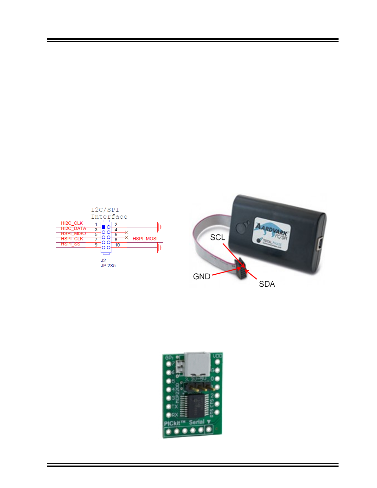
1.1.1 Aadvark I2C Host Adapter
Aardvark I2C/HCI Host adapter is used to interface PC via USB to I2C pins of ATWINC/ATWILC. The
same is shown in the following figure. For more information, refer to http://www.totalphase.com/products/
aardvark-i2cspi/.
Figure 1-1. Aardvark I2C/HCI Host Adapter
ATWINC/ATWILC/ATSAMB/ATBTLC
Prerequisite
1.1.2 USB - UART Converter
This USB-UART converter (MCP2200) Breakout Module) will be used to interface PC to the UART DTM
interface of ATWINC3XXX, ATBTLC1000 and ATSAMB11 devices. Any generic USB-UART converter can
also be used.
Figure 1-2. USB - UART Converter
© 2019 Microchip Technology Inc.
User Guide
DS50002893A-page 4
Page 5
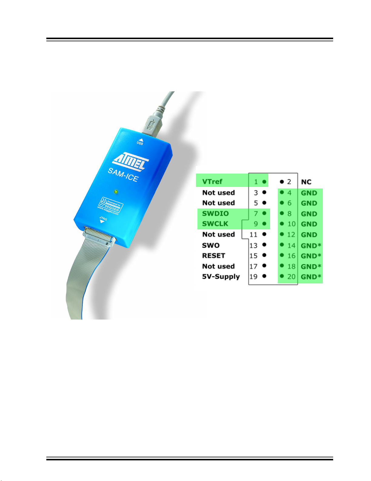
1.1.3 JTAG Emulator
The AT91SAM-ICE is a JTAG emulator designed for ARM® core based MCUs and MPUs. It is used to
program test firmware. For more information, refer to http://www.microchip.com/DevelopmentTools/
ProductDetails.aspx?PartNO=at91sam-ice
Figure 1-3. AT91SAM-ICE JTAG Emulator
ATWINC/ATWILC/ATSAMB/ATBTLC
Prerequisite
1.2 Software Prerequisite
1.2.1 Serial Bridge Connection (ATWILC/ATWINC)
MCHPRT2 GUI can be operated without the Aadvark tool with the help of serial bridge application from
Atmel Studio. In the GUI, instead of I2C select UART. Enter the valid Com port, baud rate and click Init to
start evaluating the RF test system. For more information, see the Serial Bridge Application Note.
1.2.2 MCHPRT2 GUI Tool
The MCHPRT2 tool allows the user to easily configure, evaluate and test an RF system. It simplifies the
effort during the early stage of development. The later sections have a detailed explanation on how the
tool is used to test the RF system.
© 2019 Microchip Technology Inc.
User Guide
DS50002893A-page 5
Page 6
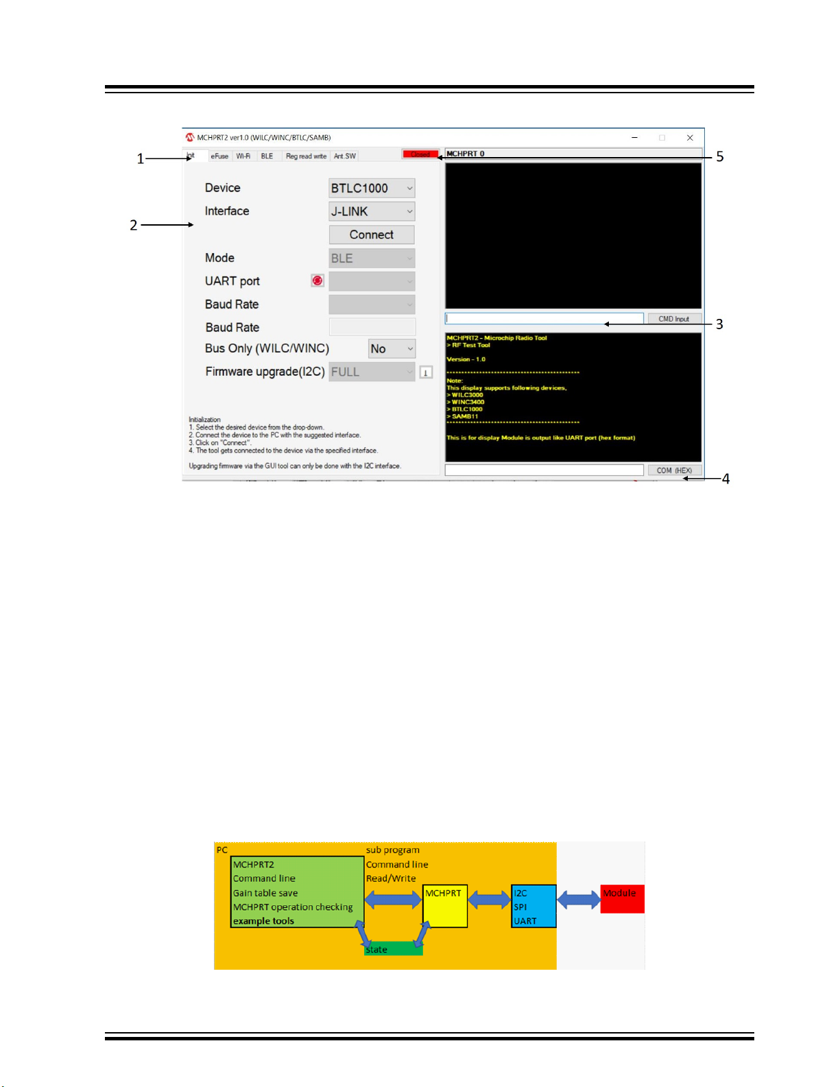
Figure 1-4. MCHPRT2 GUI Tool
ATWINC/ATWILC/ATSAMB/ATBTLC
Prerequisite
1. Click the tab for Initialization, eFuse, Wi-Fi, BLE or Register read and write option.
2. It is a function block for the selected tab.
3. CMD command line block.
4. Com port block.
5. Device connectivity status:
– Close: Sub process "MCHPRT" is close.
– Ready: "MCHPRT" is waiting for the command.
– Processing: "MCHPRT" is running.
1.2.2.1 MCHPRT2 Software Architecture
MCHPRT2 is a C# program using MCHPRT command line function for RF test or automation test
example. The following link has an example of process function to open, send and receive the command.
https://docs.microsoft.com/en-us/dotnet/api/system.diagnostics.process?
redirectedfrom=MSDN&view=netframework-4.7.2.
The following is the architecture of MCHPRT2.
Figure 1-5. MCHPRT2
© 2019 Microchip Technology Inc.
User Guide
DS50002893A-page 6
Page 7

For MCHPRT2 source code contact Microchip sales.
1.3 UART/I2C Pin Details
Connect the UART or I2C to PC, and power on the ATWINC/ATWILC/ATBTLC/ATSAMB. Ensure that
ATWINC/ATWILC/ATBTLC/ATSAMB is in the right test mode with the correct pins.
The following table provides the I2C connection for ATWINC/ATWILC 1XXX and 3XXX series.
Table 1-1. I2C Connection
Connections 1XXX Module series 1XXX Chip series 3XXX Module series 3XXX Chip series
I2C Slave Data Pin 3 Pin 33 Pin 10 Pin 16
I2C Slave clock Pin 2 Pin 32 Pin 11 Pin 17
BT_TXD NA NA Pin 8 Pin 14
BT_RXD NA NA Pin 9 Pin 15
Connect the J-Link and power on the ATBTLC/ATSAMB-ZR series. Connect the BT_TXD and BT_RXD
lines to the UART input pins of an USB-UART converter.
ATWINC/ATWILC/ATSAMB/ATBTLC
Prerequisite
The following table provides the J-Link connection for ATBTLC/ATSAMB series. Pin 41-49 is ground
exposed paddle; it must be soldered to system ground.
Table 1-2. J-Link Connection
Connections ATBTLC ZR
Module series
SWCLK Pin 12 Pin 35 Pin 12 Pin 35
SWDIO Pin 13 Pin 36 Pin 13 Pin 36
BT_TXD Pin 15 Pin 38 Pin 15 Pin 38
BT_RXD Pin 14 Pin 37 Pin 14 Pin 37
Note: MCHPRT/MCHPRT2/HCI_Command tools have DTR enable or disable function on UART.
For example:
SAMB11 Xpro board serial port setting is different, which only supports the following conditions:
serialport.DtrEnable = true;
serialport.Handshake = Handshake.RequestToSend;
serialport.RtsEnable = true;
In MCHPRT/MCHPRT2/hci_command tools DTR must be enabled.
ATBTLC ZR Chip
series
ATSAMB ZR
Module series
ATSAMB ZR Chip
series
1.4 Power-Up/Down Sequence
This section provides the power-up/down sequence for ATWINC/ATWILC/ATSAMB/ATBTLC.
© 2019 Microchip Technology Inc.
User Guide
DS50002893A-page 7
Page 8
ATWINC/ATWILC/ATSAMB/ATBTLC
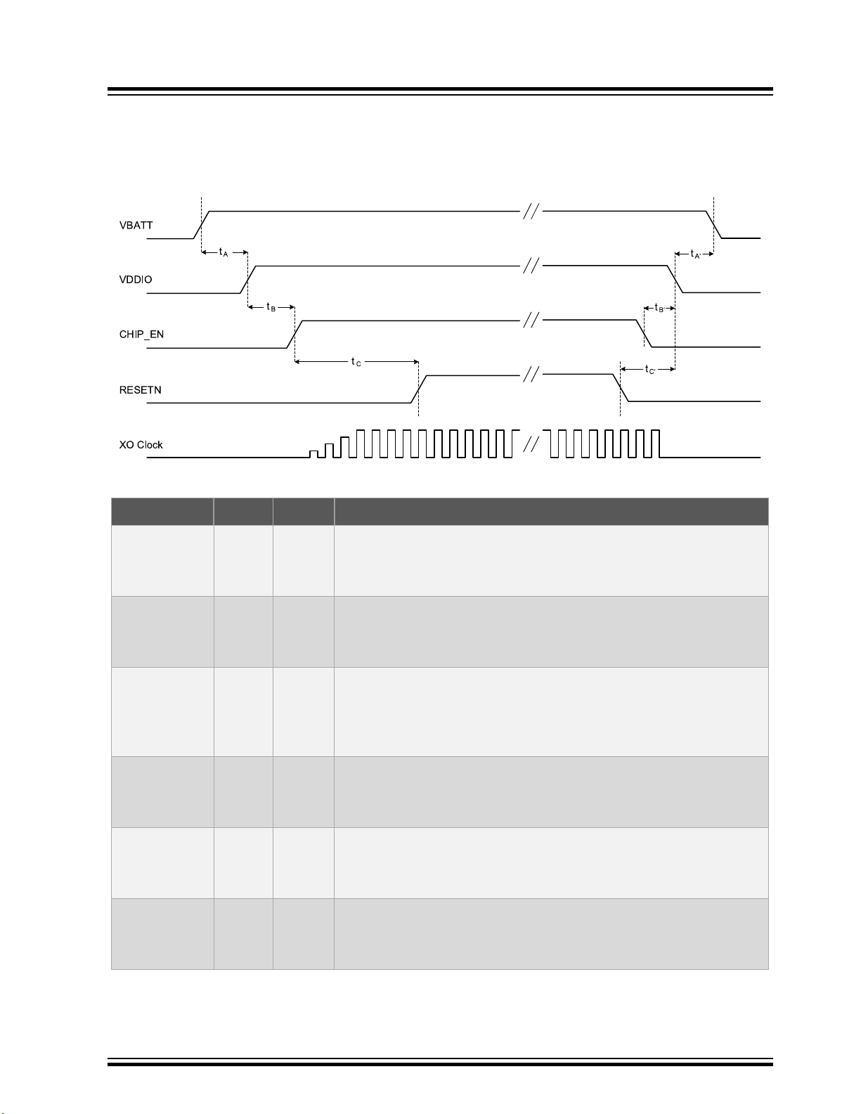
1.4.1 Power-up/down Sequence (ATWINC/ATWILC)
The power-up/down sequence for ATWINC/ATWILC is shown in the following figure. The timing
parameters are provided in following the table.
Figure 1-6. Power-up/down Sequence (ATWINC/ATWILC)
Prerequisite
Table 1-3. Power-up/down Sequence Timing Parameters
Parameter Min. Units Description
• VBATT rise to VDDIO rise
t
A
0 ms
• VBATT and VDDIO can rise simultaneously or can be tied
together. VDDIO must not rise before VBATT.
• VDDIO rise to CHIP_EN rise
t
B
0 ms
• CHIP_EN must not rise before VDDIO. CHIP_EN must be
driven high or low, not left floating.
• CHIP_EN rise to RESETN rise
t
C
5 ms
• This delay is needed because the XO clock must stabilize
before RESETN removal. RESETN must be driven high or low,
not left floating.
• VDDIO fall to VBATT fall
t
A’
0 ms
• VBATT and VDDIO can fall simultaneously or can be tied
together. VBATT must not fall before VDDIO.
• CHIP_EN fall to VDDIO fall
t
B’
0 ms
• VDDIO must not fall before CHIP_EN. CHIP_EN and RESETN
can fall simultaneously.
t
C’
© 2019 Microchip Technology Inc.
0 ms
• RESETN fall to VDDIO fall
• VDDIO must not fall before RESETN. RESETN and CHIP_EN
can fall simultaneously.
User Guide
DS50002893A-page 8
Page 9
ATWINC/ATWILC/ATSAMB/ATBTLC
It is mandatory that the ATWINC/ATWILC chip is in the right bootloader state for establishing connection
from GUI through I2C. To do that, the host MCU must power-up the ATWINC/ATWILC chip and then
perform the reset sequence as defined in the figure Power-up/down Sequence (ATWINC/ATWILC). This
is done very easily from the host MCU by calling the nm_bsp_init() and nm_bsp_reset() function. The
code snippet for the same is as shown below,
int main(void)
{/* Initialize the board. */
system_init();
/* Initialize the BSP. */
nm_bsp_init();
nm_bsp_reset();
while(1) {
}
}
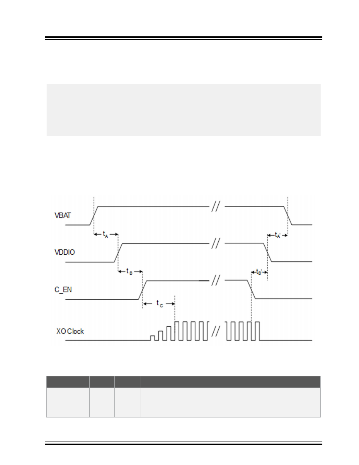
1.4.2 Power-up/down Sequence (ATBTLC/ATSAMB)
The power-up/down sequence for ATBTLC/ATSAMB is shown in the following figure. The timing
parameters are provided in following the table. For SAMB11, ensure that the steps referred in Appendix
A5 Erase and Program SAMB11 are followed before establishing connection with MCHPRT2 GUI.
Figure 1-7. Power-up/down Sequence (ATBTLC/ATSAMB)
Prerequisite
Note: Pull the A0_GPIO_0 (Wake Up pin) High during the test.
Table 1-4. Power-up/down Sequence Timing Parameters
Parameter Min. Units Description
• VBAT rise to VDDIO rise
t
A
0 ms
• VBAT and VDDIO can rise simultaneously or can be tied
together.
© 2019 Microchip Technology Inc.
User Guide
DS50002893A-page 9
Page 10
ATWINC/ATWILC/ATSAMB/ATBTLC
...........continued
Parameter Min. Units Description
• VDDIO rise to C_EN rise
t
B
0 ms
• C_EN must not rise before VDDIO. C_EN must be driven high
or low, not left floating.
Prerequisite
t
C
t
A’
t
B’
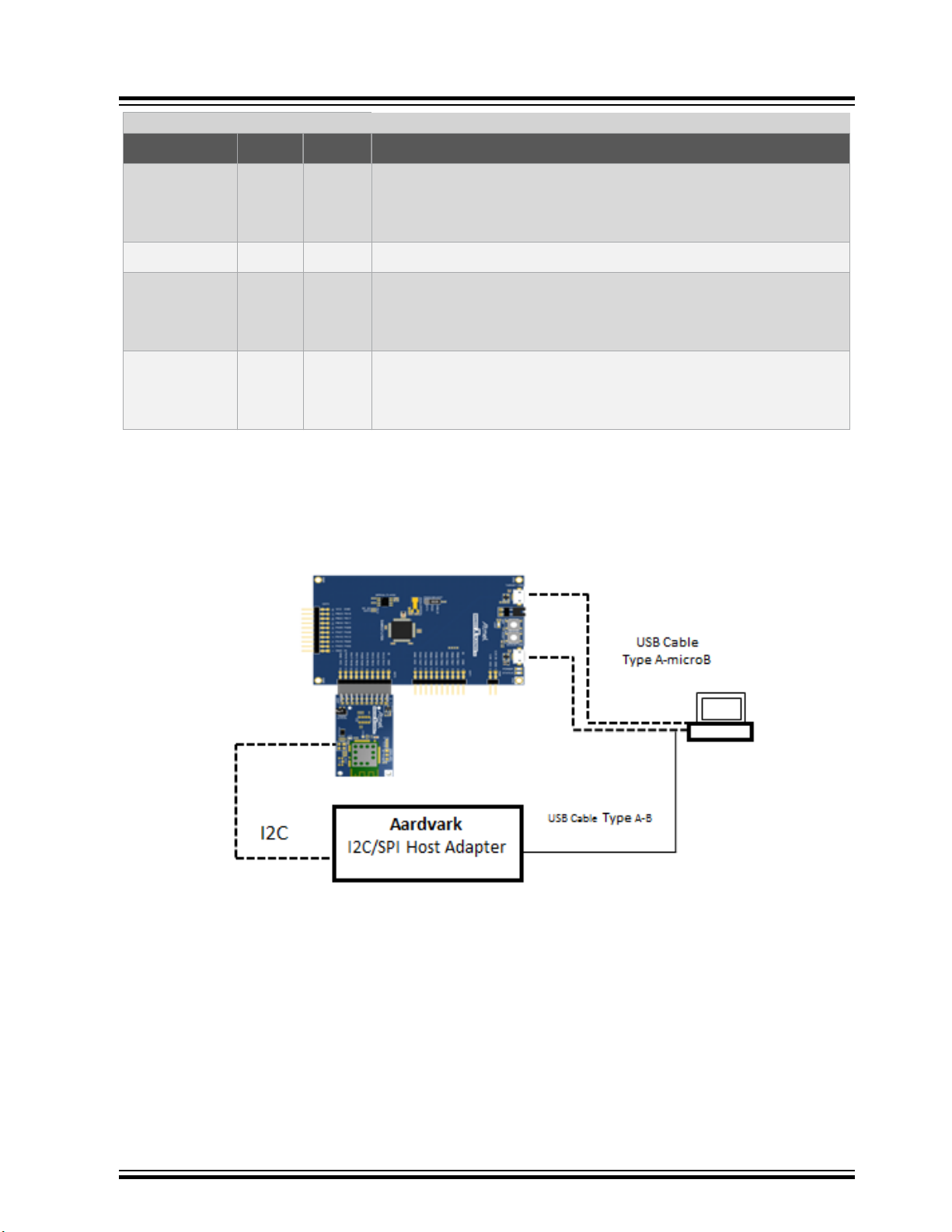
1.5 Hardware Setup
The following figures illustrate the block diagram of the test setup using ATWINC.
Figure 1-8. ATWINC1500 Hardware Setup
10 ms C_EN rise to 31.25 kHz (2 MHz/64) oscillator stabilizing
• VDDIO fall to VBAT fall
0 ms
• VBAT and VDDIO can fall simultaneously or can be tied
together.
• C_EN fall to VDDIO fall
0 ms
• C_EN must fall before VDDIO. C_EN must be driven high or
low, not left floating.
© 2019 Microchip Technology Inc.
User Guide
DS50002893A-page 10
Page 11
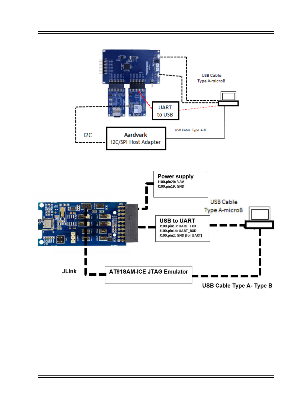
Figure 1-9. ATWINC3400 Hardware Setup
ATWINC/ATWILC/ATSAMB/ATBTLC
Prerequisite
Figure 1-10. ATBTLC Hardware Setup
Note: AO_GPIO_0 and CHIP_EN pins to be pulled to logic HIGH as per the Power-up/down Sequence.
© 2019 Microchip Technology Inc.
User Guide
DS50002893A-page 11
Page 12
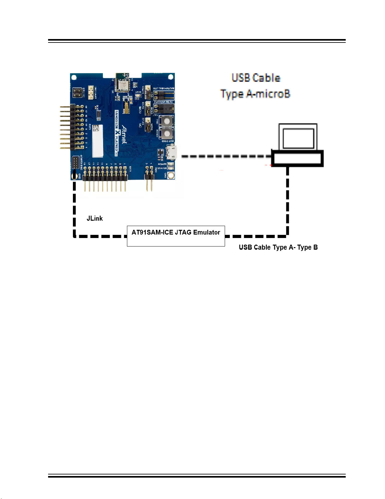
Figure 1-11. ATSAMB Hardware Setup
ATWINC/ATWILC/ATSAMB/ATBTLC
Prerequisite
Note: AO_GPIO_0 and CHIP_EN pins to be pulled to logic HIGH as per the Power-up/down Sequence.
Prior to connecting to the GUI, follow the steps mentioned in 7. Appendix D - Erase and Program
ATSAMB11.
© 2019 Microchip Technology Inc.
User Guide
DS50002893A-page 12
Page 13
2. Graphical User Interface
This chapter provides the steps to follow to put the device in Wi-Fi and Bluetooth test mode, and set
registers, eFuse bits and perform firmware upgrade using the MCHPRT2 tool.
2.1 Wi-Fi
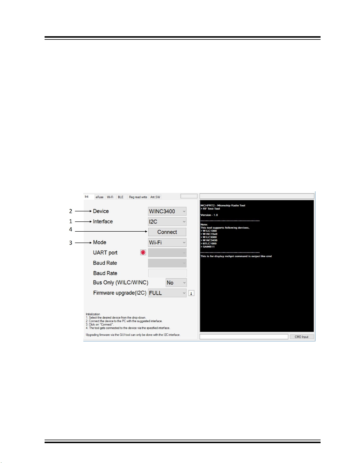
2.1.1 Initialization
Perform the following steps for Wi-Fi initialization.
1. Double-click to open the MCHPRT2.exe executable file and, select the interface as “I2C” when
using “I2C” connection. Select the interface as ‘UART’ when using serial bridge UART connection.
2. Select the device from the Device series drop down box.
3. Choose Wi-Fi as the mode from the drop down box.
4. Click Connect to initialize the device.
5. After initialization is complete, the status of the process bar displays Ready.
Figure 2-1. Wi-Fi Initialization
ATWINC/ATWILC/ATSAMB/ATBTLC
Graphical User Interface
Note: The CLI information is displayed on the right hand side.
© 2019 Microchip Technology Inc.
User Guide
DS50002893A-page 13
Page 14
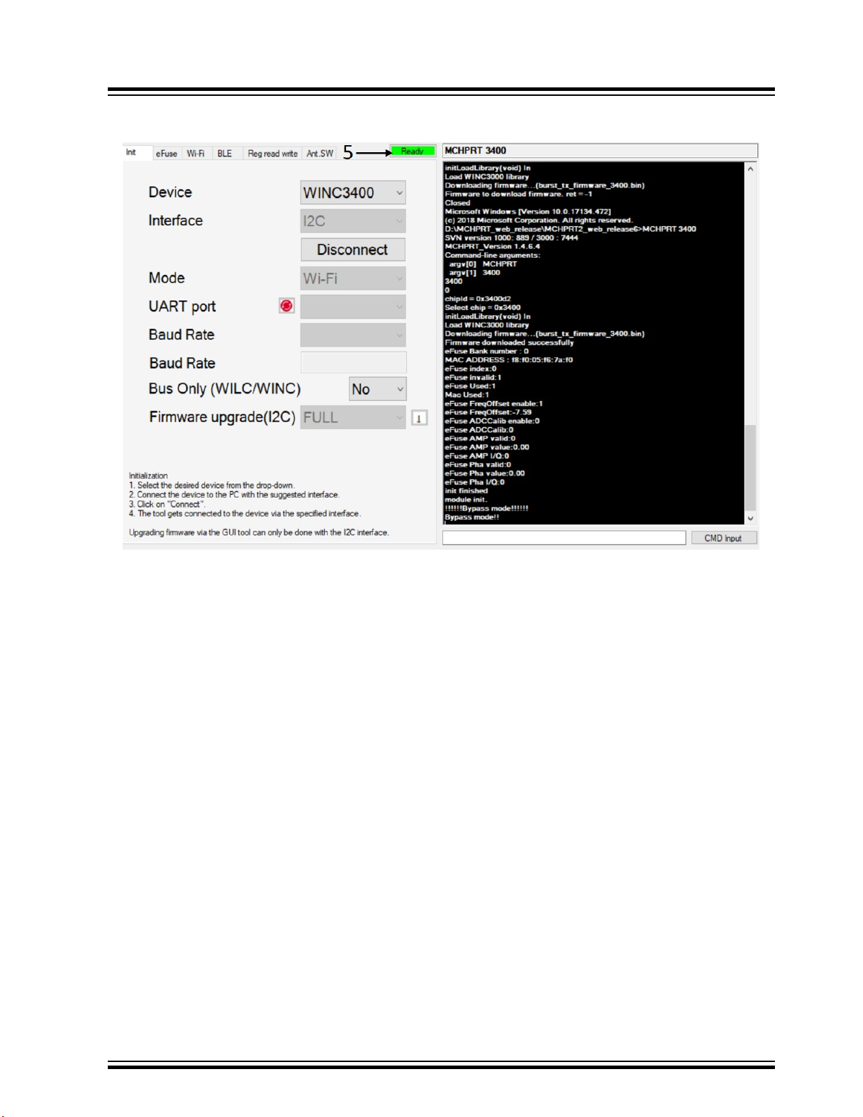
Figure 2-2. Wi-Fi Initialization
ATWINC/ATWILC/ATSAMB/ATBTLC
Graphical User Interface
2.1.2 Transmission (TX)
2.1.2.1 Start TX - Gain, Channel, Data Rate
Set the following parameters to Start TX:
1. Navigate to the Wi-Fi tab.
2. Select the desired channel CH for testing.
3. Select the desired data rate from the drop down box and choose the Gain mode (Dynamic/Bypass/
FLASH(WINC1500/WINC3400 only).
Note: In Bypass mode, PPA, PA, and Digital Gain are enabled. The value is set within the
specified value besides PPA, PA, and Digital Gain. In Dynamic and Flash gain mode, PPA, PA, and
Digital Gain are disabled.
4. Enter PPA.
5. Enter PA.
6. Enter Digital Gain (-7 ~ -15).
7. XO offset.
8. Length (0~1024).
9. Frames ( 0 for con’t TX mode).
10. For CW mode of transmission select the check box before Normal, to enter CW mode.
11. Click TX start to Start TX.
© 2019 Microchip Technology Inc.
User Guide
DS50002893A-page 14
Page 15
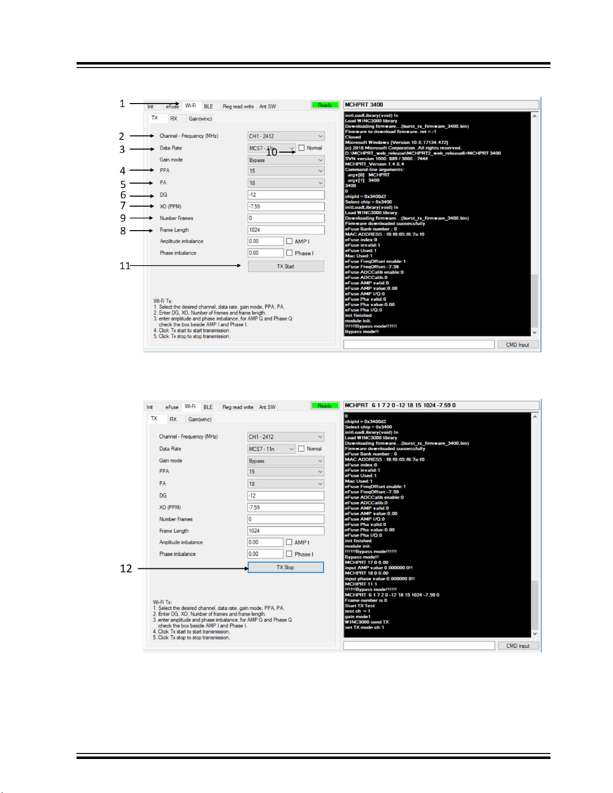
Figure 2-3. Start Tx
ATWINC/ATWILC/ATSAMB/ATBTLC
Graphical User Interface
12. Click TX stop to Stop TX.
Figure 2-4. Stop Tx
Note: The value that is written to amplitude and phase imbalance in the Wi-Fi tab is used for testing. It is
not written into the eFuse.
© 2019 Microchip Technology Inc.
User Guide
DS50002893A-page 15
Page 16
Note:
• Bypass mode: Gain values are used from the value entered in the GUI.
• Dynamic mode: Gain Values are used from the loaded test firmware (.bin gain table).
• Flash mode (For WINC devices): Gain values are used from Flash memory.
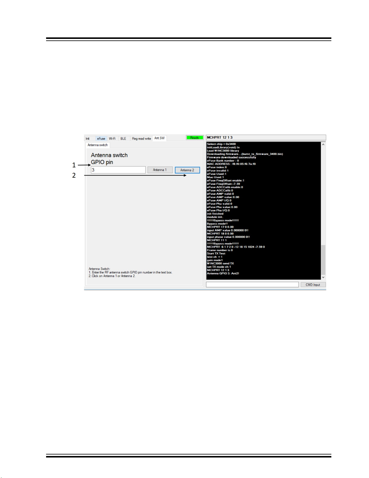
2.1.2.2 Antenna Switch
Set the following parameters for Antenna switch (ATWILC1000/ATWINC15x0).
1. Enter the GPIO number for switching the antenna.
2. Click on the Antenna 2 button for switching.
Figure 2-5. Enable Antenna Switch
ATWINC/ATWILC/ATSAMB/ATBTLC
Graphical User Interface
2.1.3 Receive (RX)
2.1.3.1 Start RX
Perform the following steps to Start RX:
1. Navigate to the RX tab, under the Wi-Fi tab.
2. Select the required channel from the Channel - Frequency (MHz) drop down box.
3. Click RX start to start the receive test.
© 2019 Microchip Technology Inc.
User Guide
DS50002893A-page 16
Page 17
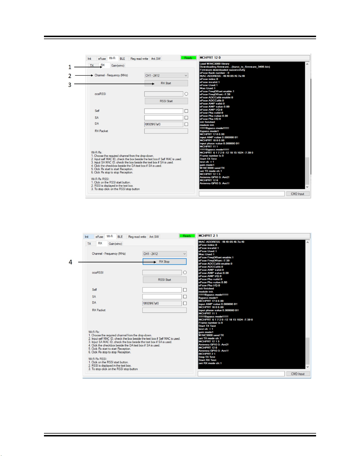
Figure 2-6. Start RX Test
ATWINC/ATWILC/ATSAMB/ATBTLC
Graphical User Interface
4. Click RX stop to stop receiving and the number of received packets is shown in RX packet text
box.
Figure 2-7. Stop RX
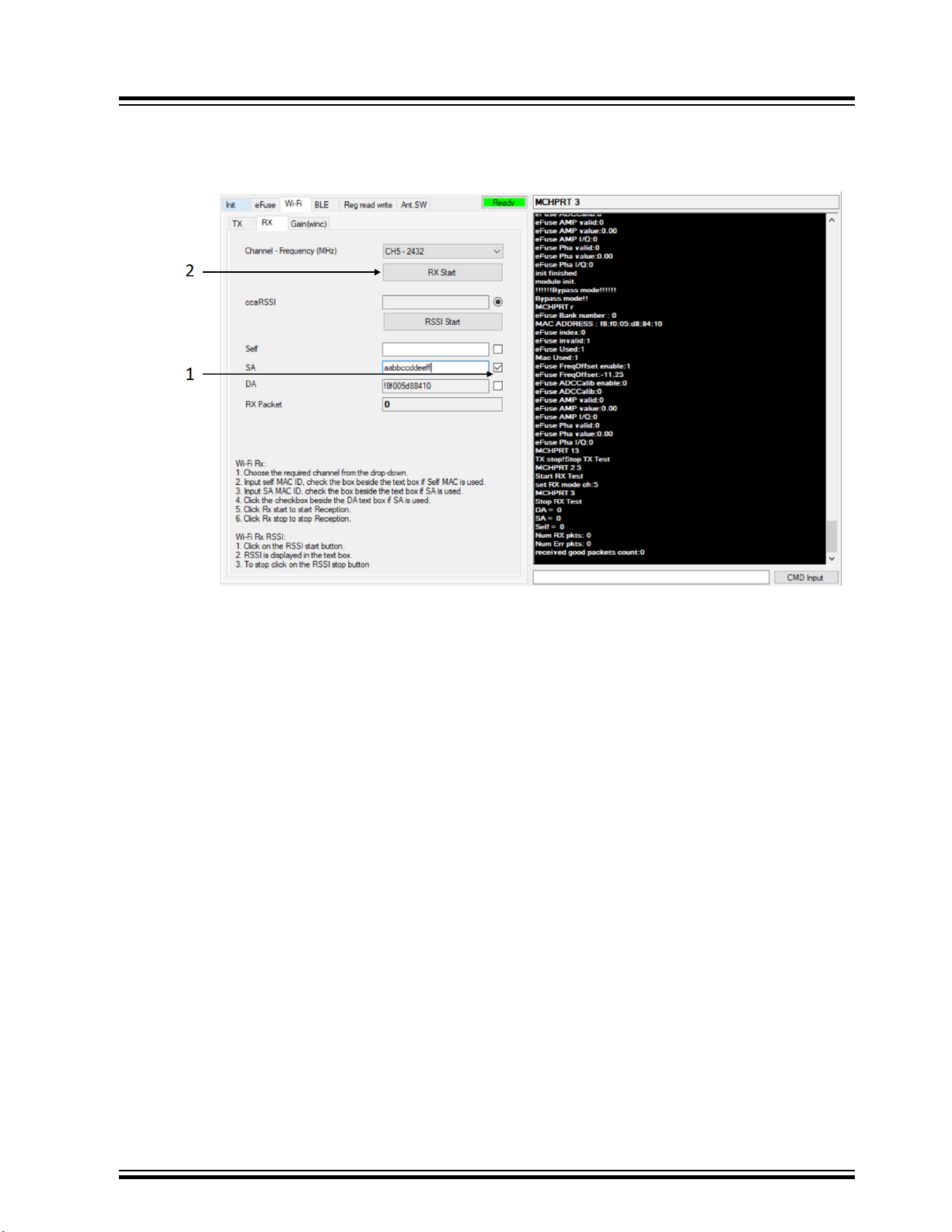
2.1.3.2 RX MAC Filter Control
2.1.3.2.1 Enable RX MAC Filter SA (Source)
Perform the following steps to enable RX MAC filter for SA.
© 2019 Microchip Technology Inc.
User Guide
DS50002893A-page 17
Page 18
ATWINC/ATWILC/ATSAMB/ATBTLC
Graphical User Interface
1. Click on the SA check box and input Source MAC address in the text box.
2. Click RX start to start the RX test.
Figure 2-8. Enable RX MAC Filter SA
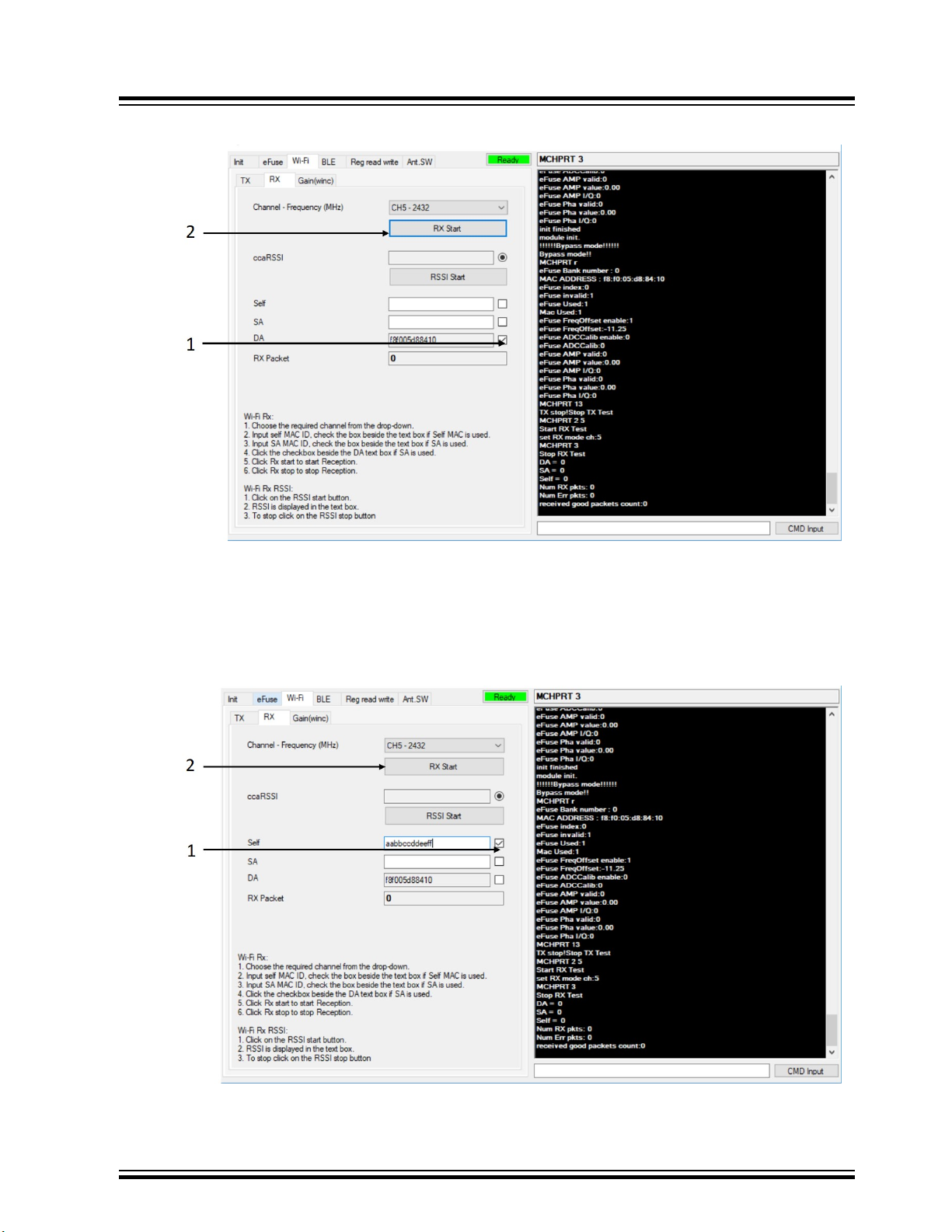
2.1.3.2.2 Enable RX MAC Filter DA (Destination)
Perform the following steps to enable RX MAC filter for DA.
1. Click the DA check box to enable RX MAC filter for DA.
2. Click on RX start to start the RX test.
© 2019 Microchip Technology Inc.
User Guide
DS50002893A-page 18
Page 19
ATWINC/ATWILC/ATSAMB/ATBTLC
Figure 2-9. Enable RX MAC Filter DA
Graphical User Interface
2.1.3.2.3 Enable Override Self MAC Address
Perform the following steps to enable override self MAC address.
1. Click on Self check box and input Self MAC address in the text box.
2. Click RX start to start the RX test.
Figure 2-10. Enable Override Self MAC Address
© 2019 Microchip Technology Inc.
User Guide
DS50002893A-page 19
Page 20
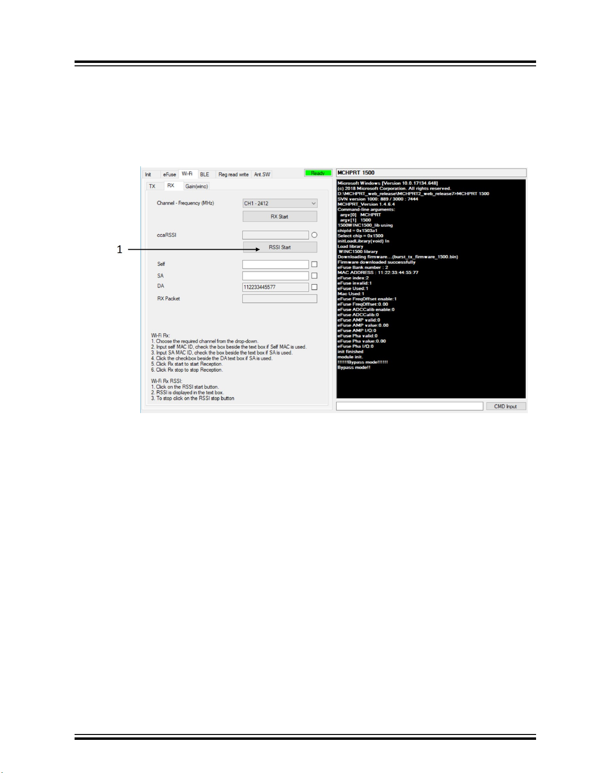
2.1.3.3 ccaRSSI
Perform the following steps to start RSSI test:
1. Click RSSI start to start receiving the signal strength displayed in the tab next to ccaRSSI.
Note: If a valid Wi-Fi packet is received, the indicator next to the ccaRSSI text box displays as
selected.
Figure 2-11. Start RSSI
ATWINC/ATWILC/ATSAMB/ATBTLC
Graphical User Interface
2. Click RSSI stop to stop measuring RSSI.
© 2019 Microchip Technology Inc.
User Guide
DS50002893A-page 20
Page 21
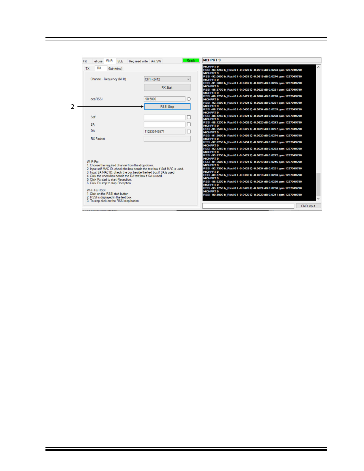
Figure 2-12. Stop RSSI
ATWINC/ATWILC/ATSAMB/ATBTLC
Graphical User Interface
2.1.4 Gain Table
Perform the following steps for Gain table settings:
1. Navigate to Gain(winc) under Wi-Fi tab and, click Get to get the Wifi-PPA, Wifi-PA and Wifi-DG.
2. Click Edit to change the values of PPA, PA and DG. Click Save to apply the changes.
© 2019 Microchip Technology Inc.
User Guide
DS50002893A-page 21
Page 22
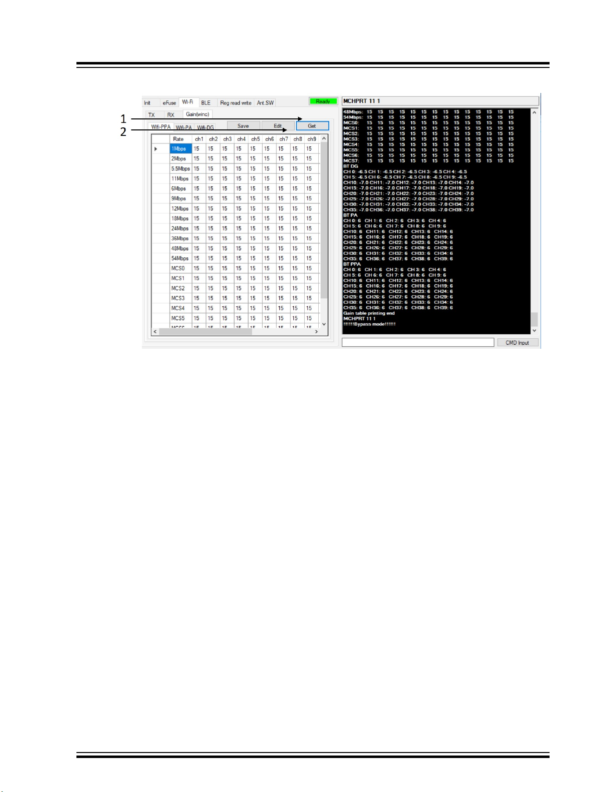
Figure 2-13. Gain Table Update
ATWINC/ATWILC/ATSAMB/ATBTLC
Graphical User Interface
2.2 Bluetooth Low Energy (ATWILC3000/ATWINC3400)
2.2.1 Initialization
Perform the following steps for Bluetooth initialization.
1. Double-click on MCHPRT2.exe to open the GUI tool and select the device from the drop down box.
2. Select the interface as “I2C” when using “I2C” connection, and as “UART” when using serial bridge
UART connection.
3. Select the Mode as BLE from the drop down box, next to Mode.
4. Click Connect.
© 2019 Microchip Technology Inc.
User Guide
DS50002893A-page 22
Page 23
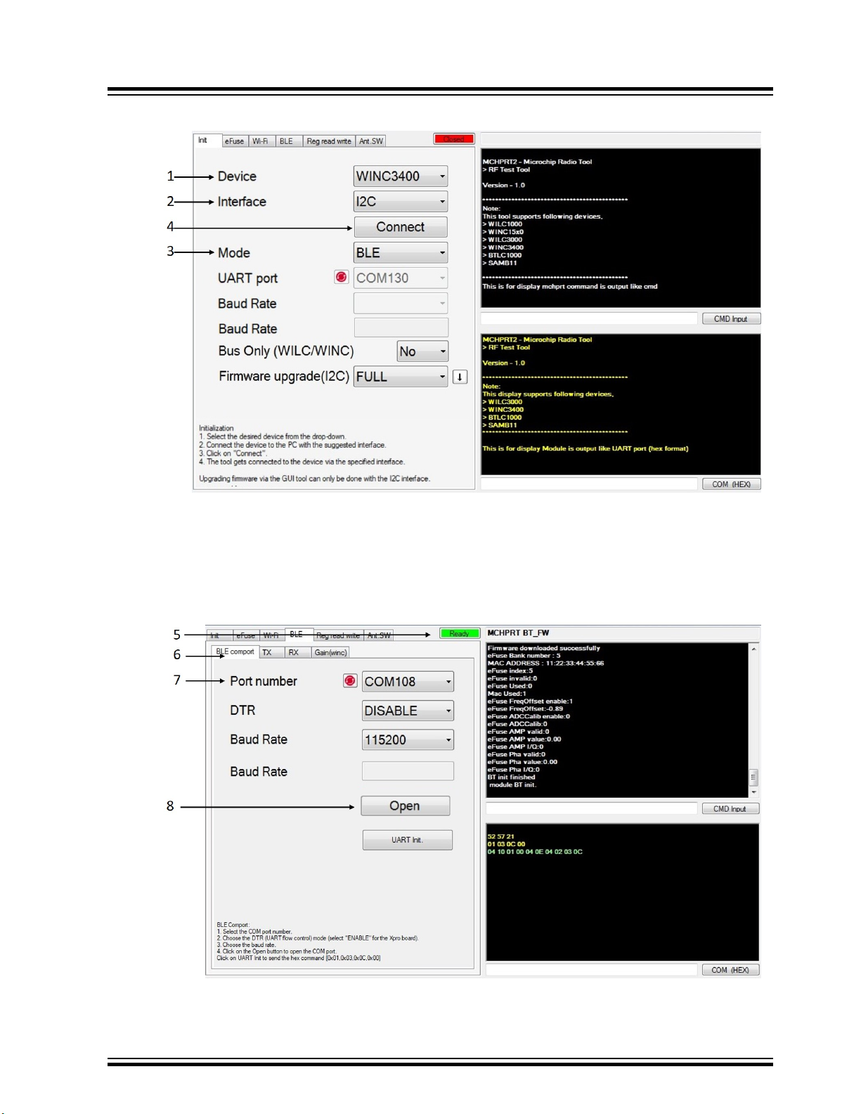
Figure 2-14. Bluetooth Initialization
ATWINC/ATWILC/ATSAMB/ATBTLC
Graphical User Interface
5. The process bar status displays Ready, after the initialization completes.
6. Navigate to BLE comport tab under BLE.
7. Select the COM port number and, select Baud rate as 115200.
8. Click Open to connect to the selected COM port.
Figure 2-15. Selecting COM Port
To check if DTR is enabled, see 1.3 UART/I2C Pin Details .
© 2019 Microchip Technology Inc.
User Guide
DS50002893A-page 23
Page 24
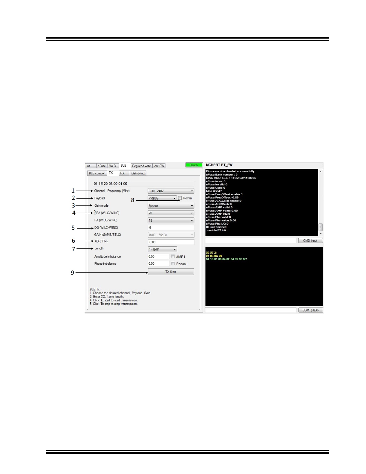
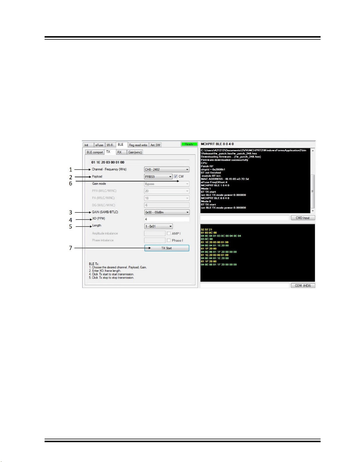
2.2.2 TX
Set the following parameters for Bluetooth TX.
ATWINC/ATWILC/ATSAMB/ATBTLC
Graphical User Interface
1. Navigate to TX tab under BLE and choose the desired channel from Channel-Frequency dropdown.
2. Select the payload.
3. Select gain mode.
4. Select PPA and PA values from the drop down box.
5. Enter Digital gain.
6. Enter XO offset.
7. Select Frame Length.
8. Select the check box next to payload drop down box, to enable CW mode.
9. Click TX Start to start transmission.
Figure 2-16. Start TX for Bluetooth
10. Click TX Stop to stop transmission.
© 2019 Microchip Technology Inc.
User Guide
DS50002893A-page 24
Page 25
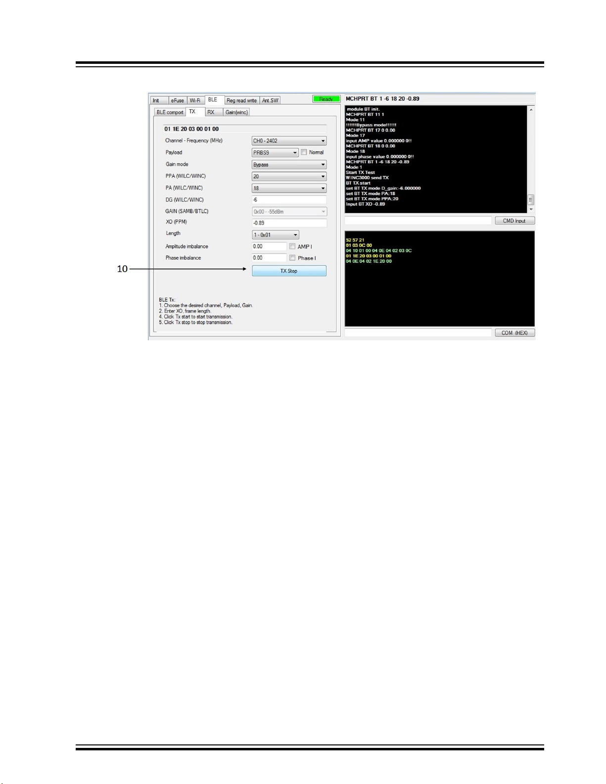
Figure 2-17. Stop TX for Bluetooth
ATWINC/ATWILC/ATSAMB/ATBTLC
Graphical User Interface
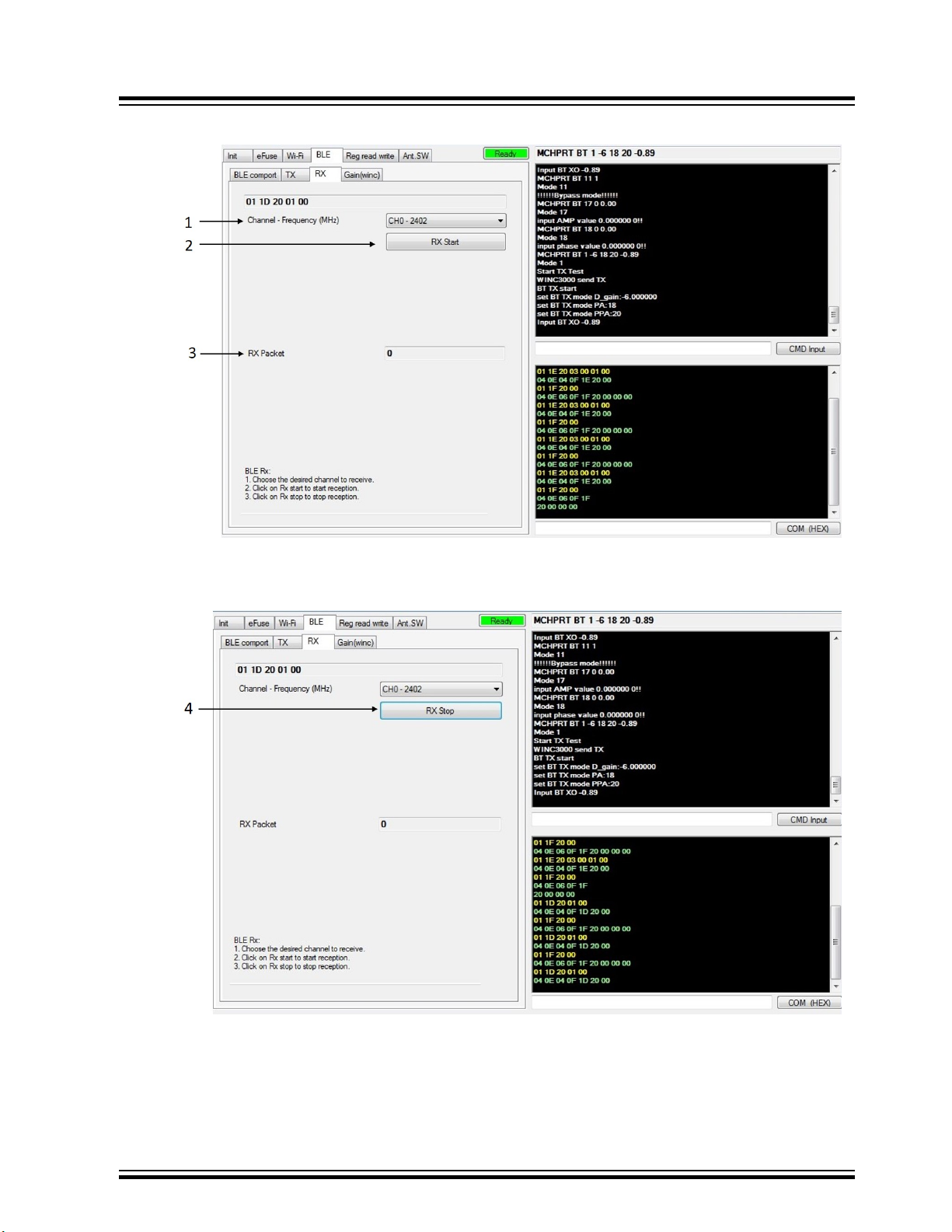
2.2.3 RX
Set the following parameters for RX test:
1. Navigate to RX tab under BLE and choose the required channel from the Channel-Frequency drop
down box.
2. Click RX start to start the reception.
3. Rx packet shows the number of successful packets received.
© 2019 Microchip Technology Inc.
User Guide
DS50002893A-page 25
Page 26
ATWINC/ATWILC/ATSAMB/ATBTLC
Figure 2-18. Start Bluetooth RX Test
Graphical User Interface
4. Click RX stop to stop the reception.
Figure 2-19. Stop Bluetooth RX Test
2.2.4 Direct Test Mode
1. Stop all the Tx or Rx tests before starting DTM mode.
2. After the BLE initialization, reconnect the COM port to the testing equipment.
© 2019 Microchip Technology Inc.
User Guide
DS50002893A-page 26
Page 27
ATWINC/ATWILC/ATSAMB/ATBTLC
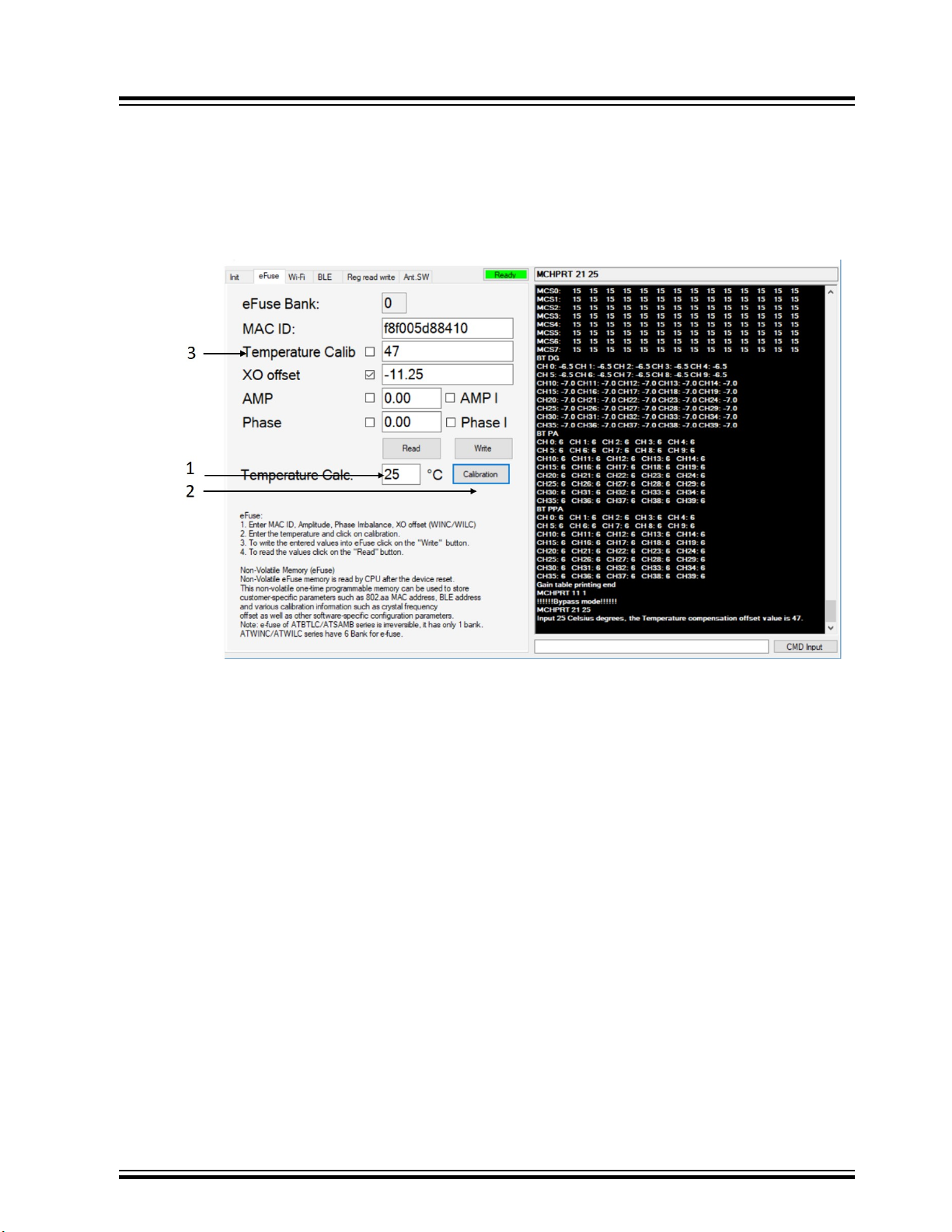
2.3 Temperature Calibration Calculator
1. Navigate to eFuse and type the current temperature value in the text box.
2. Click Calibration.
3. The calibrated temperature value is displayed in the text box beside Temperature Calib.
Figure 2-20. Temperature calibration procedure
Graphical User Interface
Note: Temperature calibration only works in Dynamic mode. The current WILC/WINC firmware
doesn’t support this feature. It is for future reference.
2.4 Bluetooth Low Energy (ATBTLC/ATSAMB)
2.4.1 Initialization
Perform the following steps for BLE initialization. For SAMB11, ensure that the steps referred in Appendix
A5 Erase and Program SAMB11 are followed before establishing connection with MCHPRT2 GUI.
1. Double click on MCHPRT2.exe to open the GUI and select the device from the drop-down.
2. Select the mode as BLE.
3. Select interface as J-link.
4. Click Connect to initialize. When the initialization is complete, the process bar status displays
Ready.
© 2019 Microchip Technology Inc.
User Guide
DS50002893A-page 27
Page 28
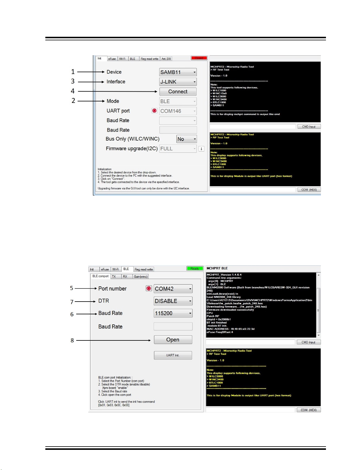
Figure 2-21. BLE Initialization
ATWINC/ATWILC/ATSAMB/ATBTLC
Graphical User Interface
Note: Select J-Link for ATBTLC/ATSAMB series and I2C or UART for ATWILC3000/ATWINC3400.
5. Navigate to BLE comport tab below BLE and choose COM port number.
6. Type ‘115200’ as baud rate.
7. Select DTR as disable for Microchip boards. Refer 1.3 UART/I2C Pin Details to check if DTR is
enabled.
8. Click Open to connect to COM port.
Figure 2-22. Selecting COM Port
© 2019 Microchip Technology Inc.
User Guide
DS50002893A-page 28
Page 29
2.4.2 TX
Set the following parameters for transmitting in BLE Test mode.
ATWINC/ATWILC/ATSAMB/ATBTLC
Graphical User Interface
1. Navigate to TX tab under BLE and choose the desired channel from Channel-Frequency drop down
box.
2. Select payload.
3. Select Gain.
4. Enter XO offset value in the text tab.
5. Select the frame length.
6. Select the check box before payload for CW mode.
7. Click TX Start to start the transmission.
Figure 2-23. Start TX for BLE
8. Click TX Stop to stop the transmission.
© 2019 Microchip Technology Inc.
User Guide
DS50002893A-page 29
Page 30
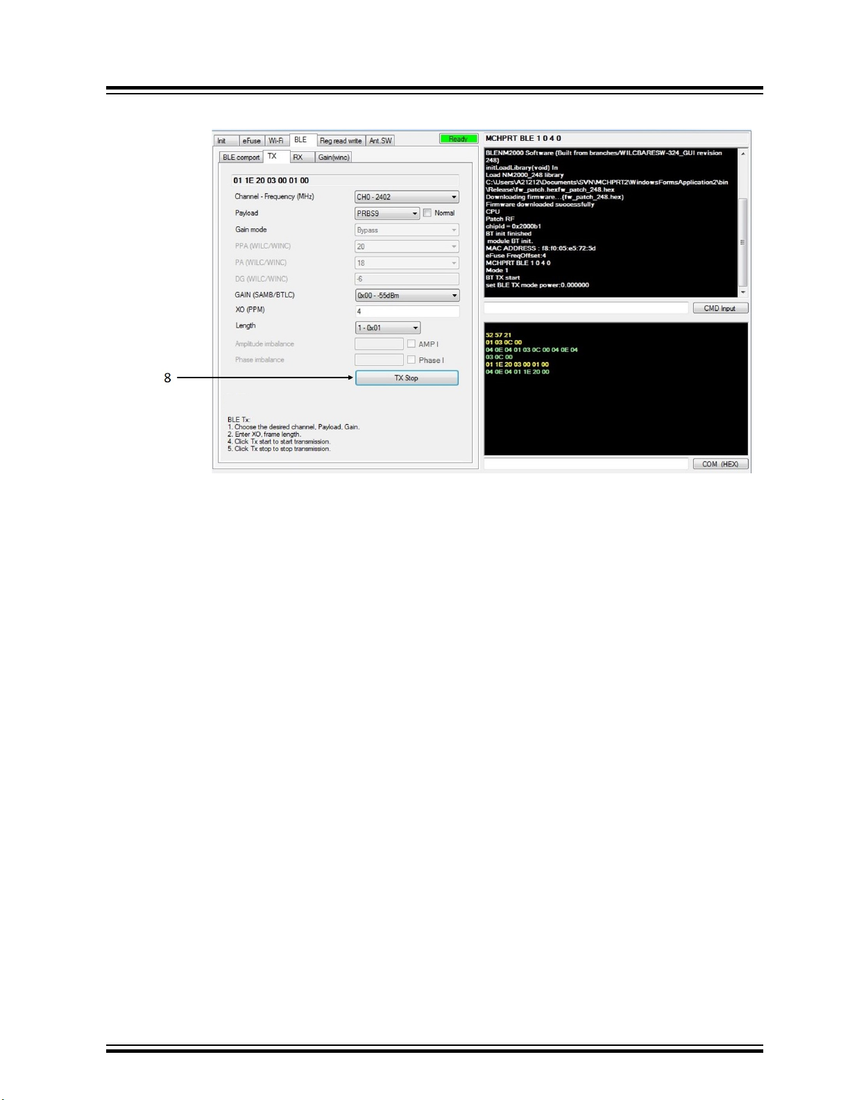
Figure 2-24. Stop TX for BLE
ATWINC/ATWILC/ATSAMB/ATBTLC
Graphical User Interface
2.4.3 RX
Set the following parameters for RX test.
1. Navigate to RX tab under BLE and choose the desired channel from the Channel-Frequency dropdown box.
2. Click RX Start to start the reception.
3. RX packet shows the number of successful packets received.
© 2019 Microchip Technology Inc.
User Guide
DS50002893A-page 30
Page 31

ATWINC/ATWILC/ATSAMB/ATBTLC
Figure 2-25. Start Bluetooth RX Test
Graphical User Interface
4. Click RX Stop to stop the reception.
Figure 2-26. Stop Bluetooth RX Test
2.4.4 Direct Test Mode
After initialization, connect the COM port to testing equipment.
© 2019 Microchip Technology Inc.
User Guide
DS50002893A-page 31
Page 32

2.5 Register
Navigate to Reg read and write tab.
2.5.1 Read
Perform the following steps to read the register values.
1. Enter the address in the Register location text tab, as shown in the following figure.
2. Click Read button to display value in the Register Value text box.
Figure 2-27. Read Reg Value
ATWINC/ATWILC/ATSAMB/ATBTLC
Graphical User Interface
2.5.2 Write
Perform the following steps to write the register values.
1. Type the register location.
2. Type the register value in the Register value text box.
3. Click Write to write into the specified location.
© 2019 Microchip Technology Inc.
User Guide
DS50002893A-page 32
Page 33
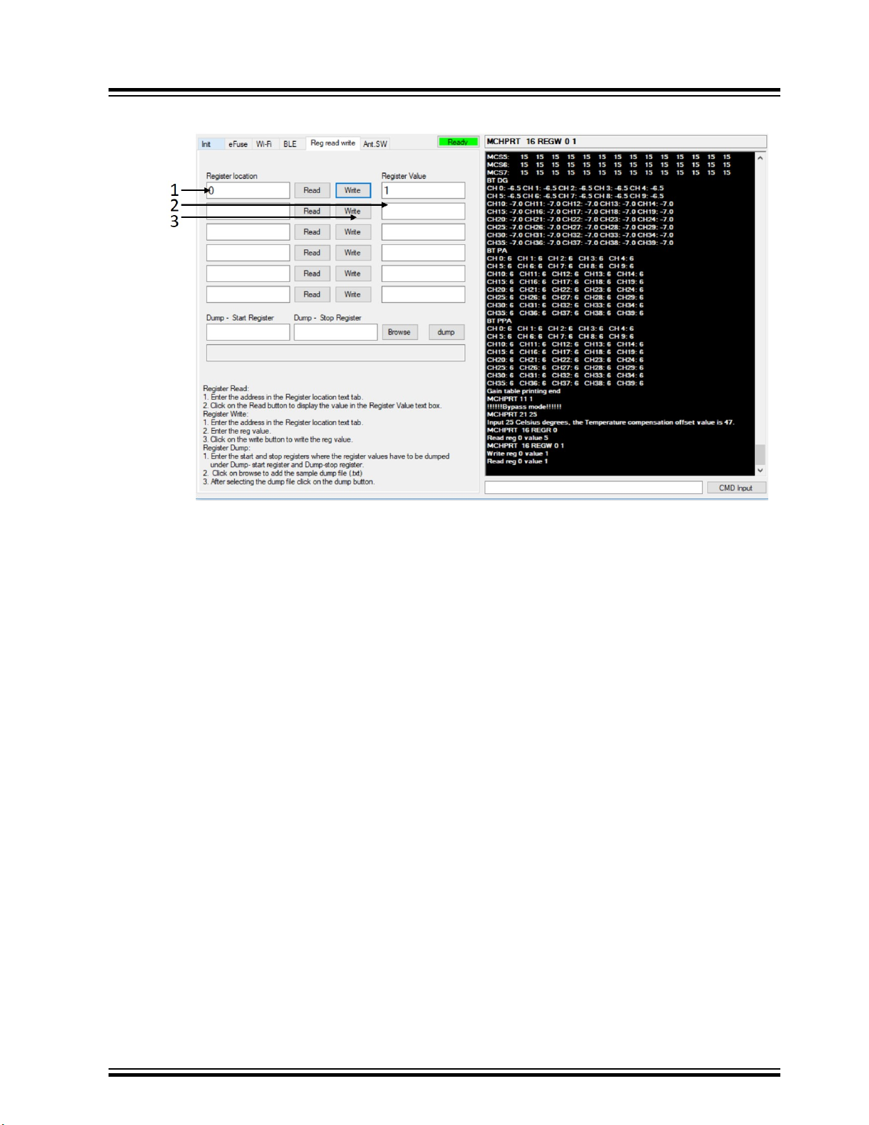
Figure 2-28. Write Reg Value
ATWINC/ATWILC/ATSAMB/ATBTLC
Graphical User Interface
2.5.3 Register Dump
Perform the following steps to dump the registers.
1. Enter the start and stop registers where the register values has to be dumped under Dump- start
register and Dump-stop register.
2. Click Browse to add the sample dump file (.txt).
3. After selecting the dump file click Dump.
© 2019 Microchip Technology Inc.
User Guide
DS50002893A-page 33
Page 34

ATWINC/ATWILC/ATSAMB/ATBTLC
Figure 2-29. Adding the Sample Dump File
Graphical User Interface
4. After dumping the registers, the process bar indicates blue color.
2.6 eFuse
2.6.1 Read
Perform the following steps to read eFuse.
1. Open MCHPRT2 GUI tool.
2. After initialization, navigate to eFuse tab.
3. Click Read to see the written parameters.
Note: The format for dump file is .txt.
© 2019 Microchip Technology Inc.
User Guide
DS50002893A-page 34
Page 35

Figure 2-30. Read eFuse
ATWINC/ATWILC/ATSAMB/ATBTLC
Graphical User Interface
2.6.2 Write
Perform the following steps to write eFuse:
1. Navigate to eFuse tab. To update gain correction, XO offset , AMP and Phase imbalance enter the
2. Click Write to write efuse.
3. If only a few parameters are required to be written to eFuse, then the other parameter follows the
4. The eFuse bank number automatically updates by +1. If the module is new, the bank will be Null.
respective values.
previous eFuse information. To confirm this enter letter "Y" in the CMD Input text box and click on
CMD Input. After the eFuse is written, "eFuse write finish" displays in the command window.
On first write, the bank number gets incremented by +1 until it reaches 5. (0-5 banks).
© 2019 Microchip Technology Inc.
User Guide
DS50002893A-page 35
Page 36

Figure 2-31. Enable eFuse Write
ATWINC/ATWILC/ATSAMB/ATBTLC
Graphical User Interface
Figure 2-32. Enter Y
2.7 Firmware Upgrade
Perform the following steps to upgrade the firmware using the MCHPRT2 Tool. It is the same firmware
upgrade example that is available in Atmel Studio. See 6. Appendix C - Firmware Update for details.
© 2019 Microchip Technology Inc.
User Guide
DS50002893A-page 36
Page 37

ATWINC/ATWILC/ATSAMB/ATBTLC
Important: Before the FW upgrade, update the firmware files in following folder:
• ..\MCHPRT\upgrade_1500\firmware\firmware (for ATWINC1500)
• ..\MCHPRT\upgrade_3400\firmware\firmware (for ATWINC3400)
1. Select the chip from the drop down menu.
2. Select the upgrade items from the list.
3. Click
to start the firmware upgrade.
Figure 2-33. FW Upgrade
Graphical User Interface
4. After the upgrade is successful, the log displays as “PASS”, see the following figure.
© 2019 Microchip Technology Inc.
User Guide
DS50002893A-page 37
Page 38

ATWINC/ATWILC/ATSAMB/ATBTLC
Graphical User Interface
Figure 2-34. Successful Upgrade
Note: ASF has the latest firmware. For information on how to add the upgrade file into MCHPRT2 tool
folder, see the Firmware upgrade folder in MCHPRT2 package.
© 2019 Microchip Technology Inc.
User Guide
DS50002893A-page 38
Page 39

3. Command Line
The commands that are sent using command line can also be sent from the GUI by entering the
command in the CMD Input text box.
3.1 Wi-Fi
3.1.1 Initialization
The following table provides the command syntax for Wi-Fi initialization.
Table 3-1. Wi-Fi Initialization
Command Syntax MCHPRT X
X X refers to Chip selection:
ATWINC/ATWILC/ATSAMB/ATBTLC
Command Line
Auto Chip Selection
• 0 – Autodetect Chip with I2C
• 0_UART – Autodetect Chip with UART
Fast Connection
• 1000 – ATWILC1000 series with I2C
• 1000_UART – ATWILC1000 series with UART
• 1500 – ATWINC15X0 series with I2C
• 1500_UART – ATWINC15X0 series with UART
• 3000 – ATWILC3000 series with I2C
• 3000_UART – ATWILC3000 series with UART
• 3400 – ATWINC3400 series with I2C
• 3400_UART – ATWINC3400 series with UART
Example MCHPRT 0
Autodetect Chip with I2C connector
MCHPRT 0_UART
Autodetect Chip with UART connector
The following figure illustrates the Wi-Fi initialization.
© 2019 Microchip Technology Inc.
User Guide
DS50002893A-page 39
Page 40

ATWINC/ATWILC/ATSAMB/ATBTLC
Figure 3-1. Console Log of Wi-Fi Initialization (MCHPRT 0)
Command Line
3.1.2 TX
3.1.2.1 Start TX - Gain, Channel, Data Rate
The following table provides the command syntax for gain, channel and data rate of the TX test.
Table 3-2. Start TX: After Initialization
Command Syntax MCHPRT 6 X Y Z A B C D L F
X X refers to TX channel: 1 to 14
• 1 – Channel 1 (2412 MHz)
• 6 – Channel 6 (2437 MHz)
• 14 – Channel 14 (2484 MHz)
© 2019 Microchip Technology Inc.
User Guide
DS50002893A-page 40
Page 41

ATWINC/ATWILC/ATSAMB/ATBTLC
...........continued
Command Syntax MCHPRT 6 X Y Z A B C D L F
Y Z Y refer to Rate, Z refers to Preamble:
Rate = 0 Preamble = 0 11b 1 Mbps -
Rate = 1 Preamble = 0 11b 2 Mbps -
Rate = 2 Preamble = 0 11b 5.5 Mbps -
Rate = 3 Preamble = 0 11b 11 Mbps -
Rate = 0 Preamble = 1 11g 6 Mbps -
Rate = 1 Preamble = 1 11g 9 Mbps -
Rate = 2 Preamble = 1 11g 12 Mbps -
Command Line
Rate = 3 Preamble = 1 11g 18 Mbps
Rate = 4 Preamble = 1 11g 24 Mbps -
Rate = 5 Preamble = 1 11g 36 Mbps -
Rate = 6 Preamble = 1 11g 48 Mbps -
Rate = 7 Preamble = 1 11g 54 Mbps -
Rate = 0 Preamble = 2 11n MCS - 0 0x80
Rate = 1 Preamble = 2 11n MCS - 1 0x81
Rate = 2 Preamble = 2 11n MCS - 2 0x82
Rate = 3 Preamble = 2 11n MCS - 3 0x83
Rate = 4 Preamble = 2 11n MCS - 4 0x84
Rate = 5 Preamble = 2 11n MCS - 5 0x85
Rate = 6 Preamble = 2 11n MCS - 6 0x86
Rate = 7 Preamble = 2 11n MCS - 7 0x87
A A refers to bandwidth:
0/1 – 20 MHz
-
B B refers to Digital Gain (Bypass mode):
Range: -20 to 0
DG: Dynamic Gain
C C refers to PA gain (Bypass mode):
• ATWILC1000/ATWINC15X0 – 9, 6, 3, 0
• ATWILC3000/ATWINC3400 – 18, 15, 12, 9, 6, 3
DG: Dynamic Gain
© 2019 Microchip Technology Inc.
User Guide
DS50002893A-page 41
Page 42

ATWINC/ATWILC/ATSAMB/ATBTLC
...........continued
Command Syntax MCHPRT 6 X Y Z A B C D L F
D D refers to PPA gain (Bypass mode):
• ATWILC1000/ATWINC15X0 – 18, 15, 12, 9, 6, 3
• ATWILC3000/ATWINC3400 – 20, 18, 15, 12, 6, 0
DG: Dynamic Gain
L L refers to length:
0 – 1500
Maximum limit is 1500
F F refers Frequency offset :
-50 to +50 base on Crystal
XO : eFuse XO value
Example MCHPRT 6 1 7 2 0 -10 18 6 1500 0
Channel 1. MCS 7 – 20 MHz, length 1500, 0 ppm, offset DG – 10, PPA 6 , PA
18
Command Line
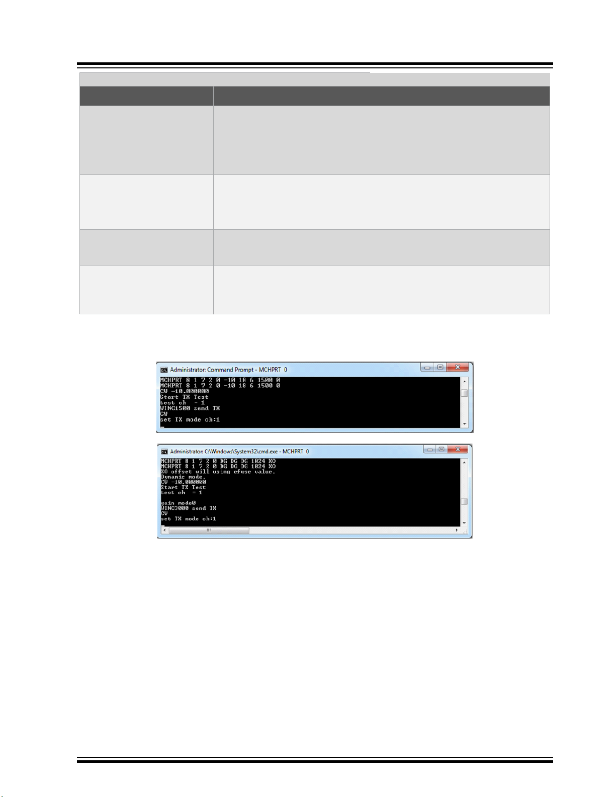
The following figure shows the example start TX test.
Figure 3-2. Console Log of TX Test Mode
The Wi-Fi TX mode starts as shown in the following figure.
© 2019 Microchip Technology Inc.
User Guide
DS50002893A-page 42
Page 43

Figure 3-3. TX Mode Start
ATWINC/ATWILC/ATSAMB/ATBTLC
Command Line
3.1.2.2 CW
The following table provides the command syntax for CW TX mode.
Table 3-3. Start TX CW: After Initialization
Command Syntax MCHPRT 8 X Y Z A B C D L F
X X refers to TX channel: 1 to 14
• 1 – Channel 1 (2412 MHz)
• 6 – Channel 6 (2437 MHz)
• 14 – Channel 14 (2484 MHz)
© 2019 Microchip Technology Inc.
User Guide
DS50002893A-page 43
Page 44

ATWINC/ATWILC/ATSAMB/ATBTLC
...........continued
Command Syntax MCHPRT 8 X Y Z A B C D L F
Y Z Y refer to Rate, Z refers to Preamble:
Rate = 0 Preamble = 0 11b 1 Mbps -
Rate = 1 Preamble = 0 11b 2 Mbps -
Rate = 2 Preamble = 0 11b 5.5 Mbps -
Rate = 3 Preamble = 0 11b 11 Mbps -
Rate = 0 Preamble = 1 11g 6 Mbps -
Rate = 1 Preamble = 1 11g 9 Mbps -
Rate = 2 Preamble = 1 11g 12 Mbps -
Command Line
Rate = 3 Preamble = 1 11g 18 Mbps
Rate = 4 Preamble = 1 11g 24 Mbps -
Rate = 5 Preamble = 1 11g 36 Mbps -
Rate = 6 Preamble = 1 11g 48 Mbps -
Rate = 7 Preamble = 1 11g 54 Mbps -
Rate = 0 Preamble = 2 11n MCS - 0 0x80
Rate = 1 Preamble = 2 11n MCS - 1 0x81
Rate = 2 Preamble = 2 11n MCS - 2 0x82
Rate = 3 Preamble = 2 11n MCS - 3 0x83
Rate = 4 Preamble = 2 11n MCS - 4 0x84
Rate = 5 Preamble = 2 11n MCS - 5 0x85
Rate = 6 Preamble = 2 11n MCS - 6 0x86
Rate = 7 Preamble = 2 11n MCS - 7 0x87
A A refers to bandwidth:
0/1 – 20 MHz
-
B B refers to Digital Gain (Bypass mode):
Range: -20 to 0
DG: Dynamic Gain
C C refers to PA gain (Bypass mode):
• ATWILC1000/ATWINC15X0 – 9, 6, 3, 0
• ATWILC3000/ATWINC3400 – 18, 15, 12, 9, 6, 3
DG: Dynamic Gain
© 2019 Microchip Technology Inc.
User Guide
DS50002893A-page 44
Page 45
ATWINC/ATWILC/ATSAMB/ATBTLC
...........continued
Command Syntax MCHPRT 8 X Y Z A B C D L F
D D refers to PPA gain (Bypass mode):
• ATWILC1000/ATWINC15X0 – 18, 15, 12, 9, 6, 3
• ATWILC3000/ATWINC3400 – 20, 18, 15, 12, 6, 0
DG: Dynamic Gain
L L refers to length:
0 – 1500
Maximum limit is 1500
F F mean Frequency offset : -50 to +50 base on Crystal
XO : eFuse XO value
Example MCHPRT 8 1 7 2 0 -10 18 6 1500 0
Channel 1. MCS 7 – 20 MHz, length 1500, 0 ppm offset DG – 10, PPA 6 ,
PA 18 CW mode
Command Line
The following figure shows the example of start CW TX mode.
Figure 3-4. Console Log of CW TX Mode
The CW TX mode starts as shown in the following figure.
© 2019 Microchip Technology Inc.
User Guide
DS50002893A-page 45
Page 46

Figure 3-5. CW TX Mode Start
ATWINC/ATWILC/ATSAMB/ATBTLC
Command Line
3.1.2.3 Gain Mode
The following table provides the command syntax for Gain mode settings.
Table 3-4. Gain Mode setting: After Initialization, Before TX Start
Command Syntax MCHPRT 11 X
X X refers to Gain mode:
Example MCHPRT 11 1
The following figure shows the example of Gain mode.
• 0 – Dynamic gain mode
• 1 – Bypass gain mode (default)
• 2 – Flash gain mode
Bypass mode
© 2019 Microchip Technology Inc.
User Guide
DS50002893A-page 46
Page 47

Figure 3-6. Console Log of Gain Mode
3.1.2.4 Antenna Switch
The following table provides the command syntax for Antenna switch (ATWILC1000/ATWINC15X0).
Table 3-5. Antenna Switching: After Initialization
Command Syntax MCHPRT 12 X Y
X X refers to Antenna:
Y Y refers to GPIO pin:
ATWINC/ATWILC/ATSAMB/ATBTLC
Command Line
• 0 – antenna 1 (default)
• 1 – antenna 2
• 3 – GPIO3
Example MCHPRT 12 0 3
The following figure shows the example of Antenna switch.
Figure 3-7. Console Log of Antenna Switch
3.1.2.5 Stop TX
The following table provides the command syntax for Stop TX test.
Table 3-6. Stop TX: After Initialization and TX Start
Command Syntax MCHPRT 13
Example MCHPRT 13
The following figure shows the example of Stop TX test.
Antenna switching A
Stop TX
© 2019 Microchip Technology Inc.
User Guide
DS50002893A-page 47
Page 48

Figure 3-8. Console Log of Stop TX Test Mode
3.1.3 RX
3.1.3.1 Start RX
The following table provides the command syntax for RX test.
Table 3-7. Start RX: After Initialization
Command Syntax MCHPRT 2 X
X X refers to TX channel: 1 to 14
ATWINC/ATWILC/ATSAMB/ATBTLC
Command Line
• 1 – Channel 1 (2412 MHz)
• 6 – Channel 6 (2437 MHz)
• 14 – Channel 14 (2484 MHz)
Example MCHPRT 2 1
The following figure shows the example of start RX test.
Figure 3-9. Console Log of RX Test Mode
3.1.3.2 Start RX with MAC Filter Selection
The following table provides the command syntax for RX test with MAC filter selection.
Table 3-8. Start RX with MAC Filter selection: After Initialization
Command Syntax MCHPRT X Y Z A
X X refers to RX mode:
RX mode in Channel 1 Start with reset the count
• 2_DA – Destination Filter
• 2_SA – Source Filter
• 2_Self – Override self MAC address
• 2_SA_DA – SA with DA
• 2_Self_DA – Self with DA
• 2_SA_Self – SA with Self
• 2_SA_Self_DA – All MAC filter apply
© 2019 Microchip Technology Inc.
User Guide
DS50002893A-page 48
Page 49

ATWINC/ATWILC/ATSAMB/ATBTLC
Command Line
...........continued
Command Syntax MCHPRT X Y Z A
Y Y refers to TX channel: 1 to 14
• 1 – Channel 1 (2412 MHz)
• 6 – Channel 6 (2437 MHz)
• 14 – Channel 14 (2484 MHz)
Z In “2_SA”, “2_SA_DA”, “2_SA_Self”, “2_SA_Self_DA”
Source MAC address
In “2_Self”, “2_Self_DA”
Self MAC address
A In “2_SA_Self_DA”
Self MAC address
Example MCHPRT 2_SA_Self_DA 1 112233445566 665544332211
RX with Source MAC filter: 112233445566 and DA MAC filter and Self
MAC address: 665544332211 in Channel 1 Start with reset the count
MCHPRT 2_SA_DA 12 112233445566
RX with Source MAC filter: 112233445566 in Channel 12 Start with
reset the count
MCHPRT 2_Self_DA 13 665544332211
RX with DA MAC filter and Self MAC address: 665544332211 in
Channel 13 Start with reset the count
The following figure shows the example of RX with Source MAC filter: 112233445566 and DA MAC filter
and Self MAC address: 665544332211 in Channel 1 Start with reset the count.
Figure 3-10. Console Log of RX with Source MAC Filter (Channel 1)
The following figure shows the example of RX with Source MAC filter: 112233445566 in Channel 12 Start
with reset the count.
Figure 3-11. Console Log of RX with Source MAC Filter (Channel 12)
© 2019 Microchip Technology Inc.
User Guide
DS50002893A-page 49
Page 50

The following figure shows the example of RX with DA MAC filter and Self MAC address: 665544332211
in Channel 13 Start with reset the count.
Figure 3-12. Console Log of RX with Source MAC Filter (Channel 13)
3.1.3.3 RX Package Report
The following table provides the command syntax for RX package report.
Table 3-9. RX Package Report: After Initialization and Start RX
Command Syntax MCHPRT 3
Example MCHPRT 3
ATWINC/ATWILC/ATSAMB/ATBTLC
Command Line
Report the package number (package count will not reset)
The following figure shows the example of RX package report.
Figure 3-13. Console Log of RX Package Report
3.1.3.4 RSSI Reading
The following table provides the command syntax for RSSI reading once.
Table 3-10. RX Package Report Once: After Initialization and Start RX
Command Syntax MCHPRT 9
Example MCHPRT 9
The following figure shows the example of RSSI reading once.
Figure 3-14. Console Log of RSSI Reading Once
Report the RSSI reading once
3.1.3.5 RSSI Reading in Seconds
The following table provides the command syntax for RSSI reading in seconds.
© 2019 Microchip Technology Inc.
User Guide
DS50002893A-page 50
Page 51

ATWINC/ATWILC/ATSAMB/ATBTLC
Table 3-11. RX Package Report: After Initialization and Start RX
Command Syntax MCHPRT 10 X
X X refers to the number of sec report the RSSI reading
Example MCHPRT 10 2
Report the RX RSSI reading in 10 sec
The following figure shows the example of RSSI reading.
Figure 3-15. Console Log of RSSI Reading
Command Line
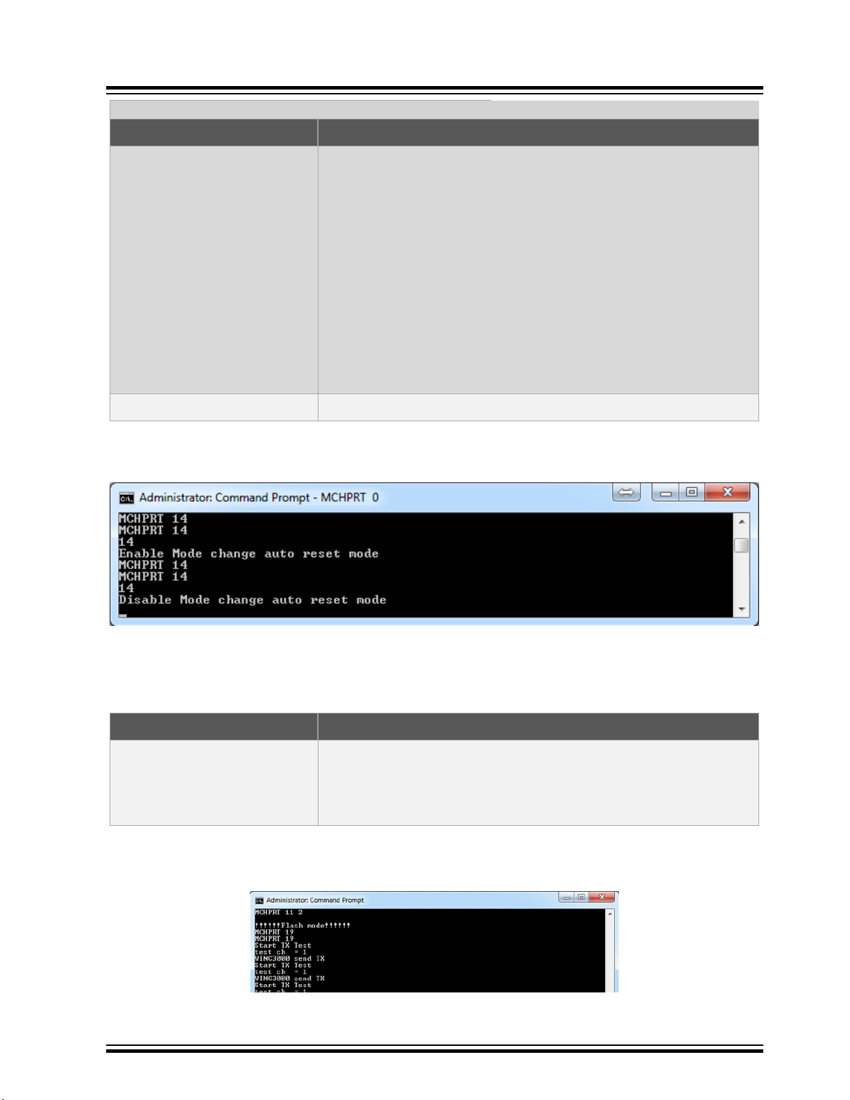
3.1.3.6 Auto Reset Mode
The following table provides the command syntax for Auto Reset mode.
Table 3-12. Auto Reset Mode
Command Syntax MCHPRT 14
Enable Enable refers to that the MCHPRT will auto reset with the mode
change
For example:
MCHPRT 8 1 7 7 0 -10 18 6 1500 0
(Module auto reset)
MCHPRT 6 1 7 7 0 -10 18 6 1500 0
(Module auto reset)
MCHPRT 2 1
© 2019 Microchip Technology Inc.
User Guide
DS50002893A-page 51
Page 52
ATWINC/ATWILC/ATSAMB/ATBTLC
Command Line
...........continued
Command Syntax MCHPRT 14
Disable (default) Disable refers that the MCHPRT will not auto reset with the mode
change. Command flow must follow the correct step.
For example:
MCHPRT 8 1 7 7 0 -10 18 6 1500 0
MCHPRT 13
MCHPRT 6 1 7 7 0 -10 18 6 1500 0
MCHPRT 13
MCHPRT 2 1
Each TX information change or change to RX mode, requires to send
stop TX command.
Example MCHPRT 14
The following figure shows the example of Auto Reset mode.
Figure 3-16. Console Log of Auto Reset Mode
3.1.3.7 Digital Gain Table Printing
The following table provides the command syntax for Digital Gain Table Printing.
Table 3-13. Digital Gain Table Printing: After Initialization and Before TX and RX
Command Syntax MCHPRT 19
Example MCHPRT 19
The following figure shows the example of Digital Gain Table Printing.
Module will start TX from Channel 1 to Channel 14 for checking gain
table and then printing the gain table in current Gain mode. This is not
applicable for Bypass mode.
Figure 3-17. Console Log of Digital Gain Table Printing
© 2019 Microchip Technology Inc.
User Guide
DS50002893A-page 52
Page 53

ATWINC/ATWILC/ATSAMB/ATBTLC
Command Line
Figure 3-18. Console Log of Display Gain Table Printing WINC3400
© 2019 Microchip Technology Inc.
User Guide
DS50002893A-page 53
Page 54

3.1.3.8 Deinitialization
The following table provides the command syntax for deinitialization.
Table 3-14. Deinitialization: After Initialization
Command Syntax MCHPRT 4
Example MCHPRT 4
ATWINC/ATWILC/ATSAMB/ATBTLC
Command Line
Deinitialization
The following figure shows the example of deinitialization.
Figure 3-19. Console Log of Deinitialization
3.2 Bluetooth (ATWILC3000/ATWINC3400)
3.2.1 Bluetooth Initialization
The following table provides the command syntax for Bluetooth initialization. Refer to 1.3 UART/I2C Pin
Details to check if DTR is enabled or not.
Table 3-15. Initialization
Command Syntax MCHPRT BT X
BT • BT refers to I2C
• BT_UART refers to UART connect
• BT_DTR refers to I2C and DTR enable
• BT_UART_DTR refers to UART connect and DTR enable
• BT_FW refers to firmware upload
X X refers to the port number for Bluetooth UART
© 2019 Microchip Technology Inc.
User Guide
DS50002893A-page 54
Page 55

ATWINC/ATWILC/ATSAMB/ATBTLC
...........continued
Command Syntax MCHPRT BT X
Example MCHPRT BT 90
The following figure shows the example of Bluetooth initialization.
Figure 3-20. Console Log of Bluetooth Initialization
Command Line
Table 3-16. Bluetooth initialization without serial port
Command Syntax MCHPRT BT
BT • BT refers to I2C
• BT_UART refers to UART connect
• BT_DTR refers to I2C and DTR enable
• BT_UART_DTR refers to UART connect and DTR enable
• BT_FW refers to firmware upload
Example MCHPRT BT
© 2019 Microchip Technology Inc.
User Guide
DS50002893A-page 55
Page 56

ATWINC/ATWILC/ATSAMB/ATBTLC
Figure 3-21. Console Log of Bluetooth Initialization without Serial Port
Command Line
3.2.2 Bluetooth DTM
The following table provides the command syntax for Bluetooth DTM mode initialization.
Table 3-17. Initialization of DTM Mode
Command Syntax MCHPRT DTM init
Example MCHPRT DTM init
The following figure shows the example of DTM initialization.
© 2019 Microchip Technology Inc.
User Guide
DS50002893A-page 56
Page 57

ATWINC/ATWILC/ATSAMB/ATBTLC
Figure 3-22. Console Log of DTM Initialization
Command Line
The following table provides the command syntax for DTM mode exit.
Table 3-18. Exit DTM Mode
Command Syntax MCHPRT 9 5
Example MCHPRT 9 5
The following figure shows the example of DTM mode exit.
Figure 3-23. Console Log of DTM Mode Exit
© 2019 Microchip Technology Inc.
User Guide
DS50002893A-page 57
Page 58

3.2.3 Bluetooth TX
The following table provides the command syntax for the Bluetooth TX test.
Table 3-19. Start Bluetooth TX: After Bluetooth Initialization
ATWINC/ATWILC/ATSAMB/ATBTLC
Command Line
Command
Syntax
X X refer to TX channel: 0 to 39
Y Y refers to Length: 0 – 37
Z Z refers to Payload: 1 – 8
A A refers to Digital Gain (Bypass mode):
MCHPRT BT 1 X Y Z A B C F
• 0 – Channel 0 (2402 MHz)
• 39 – Channel 39 (2480 MHz)
• 1 - 0x1
• 37 – 0x25
• 1 – PRBS9
• 2 – 11110000
• 3 – 10101010
• 4 – PRBS15
• 5 – 11111111
• 6 – 00000000
• 7 – 00001111
• 8 – 01010101
Range : -20 to 0
DG: Dynamic Gain
B B refers PA gain (Bypass mode):
• ATWILC1000/ATWINC15X0 – 9, 6, 3, 0
• ATWILC3000/ATWINC3400 – 18, 15, 12, 9, 6, 3
DG: Dynamic Gain
C C refers to PPA gain (Bypass mode):
• ATWILC1000/ATWINC15X0 – 18, 15, 12, 9, 6, 3
• ATWILC3000/ATWINC3400 – 20, 18, 15, 12, 6, 0
Dynamic Gain
F F refers to Frequency offset :
-50 to +50 base on Crystal
XO : eFuse XO value
Example MCHPRT BT 1 0 37 0 -6 6 6 XO
Channel 0. 0x25 length, PRBS9 DG – 10, PPA 6 , PA 6
The following figure shows the example of Bluetooth TX test mode.
© 2019 Microchip Technology Inc.
User Guide
DS50002893A-page 58
Page 59

ATWINC/ATWILC/ATSAMB/ATBTLC
Figure 3-24. Console Log of Bluetooth TX Test Mode
Command Line
The Bluetooth TX mode starts as shown in the following figure.
© 2019 Microchip Technology Inc.
User Guide
DS50002893A-page 59
Page 60

Figure 3-25. BT TX Mode Start
ATWINC/ATWILC/ATSAMB/ATBTLC
Command Line
Table 3-20. Start Bluetooth TX: After Bluetooth Initialization without Serial Port Connection
Command Syntax MCHPRT BT 1 X Y Z A B C F
A A refers to Digital Gain (Bypass mode):
Range : -20 to 0
DG: Dynamic Gain
B B refers PA gain (Bypass mode):
• ATWILC1000/ATWINC15X0 – 9, 6, 3, 0
• ATWILC3000/ATWINC3400 – 18, 15, 12, 9, 6, 3
Dynamic Gain
C C refers to PPA gain (Bypass mode):
• ATWILC1000/ATWINC15X0 – 18, 15, 12, 9, 6, 3
• ATWILC3000/ATWINC3400 – 20, 18, 15, 12, 6, 0
Dynamic Gain
F F refers to Frequency offset :
-50 to +50 base on Crystal
XO : eFuse XO value
Example MCHPRT BT 1 -6 6 6 XO
DG – 10, PPA 6 , PA 6
© 2019 Microchip Technology Inc.
User Guide
DS50002893A-page 60
Page 61

ATWINC/ATWILC/ATSAMB/ATBTLC
Figure 3-26. Bluetooth Tx Log without Serial Port Connection
Command Line
3.2.3.1 CW
The following table provides the command syntax for the Bluetooth TX CW mode.
Table 3-21. Start Bluetooth TX CW: After Bluetooth Initialization with serial port
Command Syntax MCHPRT BT 2 X Y Z A B C F
X X refer to TX channel: 0 to 39
Y Y refers to Length: 0 – 37
© 2019 Microchip Technology Inc.
• 0 – Channel 0 (2402 MHz)
• 39 – Channel 39 (2480 MHz)
• 1 – 0x1
• 37 – 0x25
User Guide
DS50002893A-page 61
Page 62

ATWINC/ATWILC/ATSAMB/ATBTLC
...........continued
Command Syntax MCHPRT BT 2 X Y Z A B C F
Z Z refers to Payload: 1 – 8
• 1 – PRBS9
• 2 – 11110000
• 3 – 10101010
• 4 – PRBS15
• 5 – 11111111
• 6 – 00000000
• 7 – 00001111
• 8 – 01010101
A A refers to Digital Gain (Bypass mode):
Range : -20 to 0
DG: Dynamic Gain
B B refers PA gain (Bypass mode):
• ATWILC1000/ATWINC15X0 – 9, 6, 3, 0
• ATWILC3000/ATWINC3400 – 18, 15, 12, 9, 6, 3
Command Line
DG: Dynamic Gain
C C refers to PPA gain (Bypass mode):
• ATWILC1000/ATWINC15X0 – 18, 15, 12, 9, 6, 3
• ATWILC3000/ATWINC3400 – 20, 18, 15, 12, 6, 0
DG: Dynamic Gain
Example MCHPRT BT 2 0 37 0 -6 6 6 18 20
Channel 0. 0x25 length, PRBS9 DG – 6, PPA 6 , PA 6 CW mode
The following figure shows the example of Bluetooth CW mode.
© 2019 Microchip Technology Inc.
User Guide
DS50002893A-page 62
Page 63

ATWINC/ATWILC/ATSAMB/ATBTLC
Figure 3-27. Console Log of Bluetooth CW Mode
The Bluetooth CW mode starts as shown in the following figure.
Figure 3-28. BT CW Mode Start
Command Line
© 2019 Microchip Technology Inc.
User Guide
DS50002893A-page 63
Page 64

ATWINC/ATWILC/ATSAMB/ATBTLC
Table 3-22. Start Bluetooth TX CW: After Bluetooth Initialization without serial port
Command Syntax MCHPRT BT 8 A B C F
A A refers to Digital Gain (Bypass mode):
Range : -20 to 0
DG: Dynamic Gain
B B refers PA gain (Bypass mode):
• ATWILC1000/ATWINC15X0 – 9, 6, 3, 0
• ATWILC3000/ATWINC3400 – 18, 15, 12, 9, 6, 3
Dynamic Gain
C C refers to PPA gain (Bypass mode):
• ATWILC1000/ATWINC15X0 – 18, 15, 12, 9, 6, 3
• ATWILC3000/ATWINC3400 – 20, 18, 15, 12, 6, 0
Dynamic Gain
F F refers to Frequency offset :
-50 to +50 base on Crystal
Command Line
Example MCHPRT BT 8 -6 6 6 XO
Figure 3-29. Console Log of Bluetooth CW Mode without Serial Port
3.2.4 Bluetooth Start RX
The following table provides the command syntax for Bluetooth RX test.
Table 3-23. Start Bluetooth RX: After Bluetooth Initialization with Serial Port
Command Syntax MCHPRT BT 3 X
X X refers to TX channel: 0 to 39
XO : eFuse XO value
DG – 6, PPA 6 , PA 6 CW mode
• 0 – Channel 0 (2402 MHz)
• 39 – Channel 39 (2480 MHz)
Example MCHPRT BT 3 0
RX mode in Channel 1 Start with reset the count
The following figure shows the example of start Bluetooth RX test.
© 2019 Microchip Technology Inc.
User Guide
DS50002893A-page 64
Page 65

Figure 3-30. Console Log of Bluetooth RX Mode
3.2.5 Bluetooth RX Package Count
The following table provides the command syntax for Bluetooth RX package count.
Table 3-24. Start Bluetooth RX Package Count: After Bluetooth Initialization with Serial Port
Command Syntax MCHPRT BT 4
Example MCHPRT BT 4
The following figure shows the example of Bluetooth RX package count.
ATWINC/ATWILC/ATSAMB/ATBTLC
Command Line
Print out good package number
Figure 3-31. Console Log of Bluetooth RX Package Count
3.2.6 BLE Deinitialization
The following table provides the command syntax for BLE deinitialization.
Table 3-25. BLE Deinitialization: After Initialization
Command Syntax MCHPRT BT 5
Example MCHPRT BT 5
The following figure shows the example of BLE deinitialization.
Figure 3-32. Console Log of BLE Deinitialization
BT Deinitialization
3.3 BLE (ATBTLC1000/ATSAMB11)
3.3.1 BLE Initialization
The following table provides the command syntax for BLE initialization. Refer 1.3 UART/I2C Pin Details
to check if DTR is enabled or not.
© 2019 Microchip Technology Inc.
User Guide
DS50002893A-page 65
Page 66

ATWINC/ATWILC/ATSAMB/ATBTLC
Command Line
Table 3-26. Initialization with Serial Port
Command Syntax MCHPRT BLE X
BLE BLE_DTR refers to enable Bluetooth UART
X X refers to the port number for Bluetooth UART
Example MCHPRT BLE 146
The following figure shows the example of BLE initialization. Refer to 1.3 UART/I2C Pin Details to check
if DTR is enabled or not.
Figure 3-33. Console Log of BLE Initialization
Table 3-27. Initialization without Serial Port
Command Syntax MCHPRT BLE
BLE BLE_DTR refers to enable Bluetooth UART
X X refers to the port number for Bluetooth UART
Example MCHPRT BLE
© 2019 Microchip Technology Inc.
User Guide
DS50002893A-page 66
Page 67

Figure 3-34. Console Log of BLE Initialization without Serial Port
3.3.2 BLE TX (Transmit)
The following table provides the command syntax for the BLE TX test.
ATWINC/ATWILC/ATSAMB/ATBTLC
Command Line
Table 3-28. Start BLE TX: After BLE Initialization with Serial Port
Command Syntax MCHPRT BLE 1 X Y Z A B
X X refer to TX channel: 0 to 39
• 0 – Channel 0 (2402 MHz)
• 39 – Channel 39 (2480 MHz)
Y Y refers to Length: 0 – 37
• 1 – 0x1
• 37 – 0x25
Z Z refers to Payload: 0 – 7
• 0 – PRBS9
• 1 – 11110000
• 2 – 10101010
• 3 – PRBS15
• 4 – 11111111
• 5 – 00000000
• 6 – 00001111
• 7 – 01010101
A A refers to Gain:
0: 0x00 1: 0x01 2: 0x02 3: 0x03 4: 0x04 5: 0x05 6: 0x06 7: 0x07 8:
0x08 9: 0x09 10: 0x0A 11: 0x0B.….….56: 0x29 57: 0x30 58: 0x3A 59:
0x3B60: 0x3C 61: 0x3D 62: 0x3E 63: 0x3F
© 2019 Microchip Technology Inc.
User Guide
DS50002893A-page 67
Page 68

ATWINC/ATWILC/ATSAMB/ATBTLC
...........continued
Command Syntax MCHPRT BLE 1 X Y Z A B
B B mean XO offset value (optional): 0-15
0thbit adds 1.25pf
st
1
bit adds 2.5pf
2nd bit adds 5pf
3rd bit adds 5pf
Example: 11 mean 1011 adds a 8.75pf load cap to circuit. Default
value 7 will apply when no input XO offset value.
Example MCHPRT BLE 1 0 37 1 14
or
MCHPRT BLE 1 0 37 1 14 11
Channel 0. 0x25 length, PRBS9 Gain setting – 0x20
In MCHPRT BLE 1 X Y Z A B command, A B are optional settings.
Command Line
The following figure shows the example of BLE TX test mode.
Figure 3-35. Console Log of BLE TX Test Mode
Table 3-29. Start BLE TX: After BLE Initialization without Serial Port
Command Syntax MCHPRT BLE 1 A B X
X X refer to TX channel: 0 to 39
• 0 – Channel 0 (2402 MHz)
• 39 – Channel 39 (2480 MHz)
A A refers to Gain:
0: 0x00 1: 0x01 2: 0x02 3: 0x03 4: 0x04 5: 0x05 6: 0x06 7: 0x07 8:
0x08 9: 0x09 10: 0x0A 11: 0x0B.….….56: 0x29 57: 0x30 58: 0x3A 59:
0x3B60: 0x3C 61: 0x3D 62: 0x3E 63: 0x3F
© 2019 Microchip Technology Inc.
User Guide
DS50002893A-page 68
Page 69

ATWINC/ATWILC/ATSAMB/ATBTLC
...........continued
Command Syntax MCHPRT BLE 1 A B X
B B mean XO offset value (optional): 0-15
0thbit adds 1.25pf
st
1
bit adds 2.5pf
2nd bit adds 5pf
3rd bit adds 5pf
Example: 11 mean 1011 adds a 8.75pf load cap to circuit. Default
value 7 will apply when no input XO offset value.
Example MCHPRT BLE 1 14 7 0
Channel 0. Gain setting – 0x20
Figure 3-36. Console Log of BLE Tx Test Mode without Serial Port
Command Line
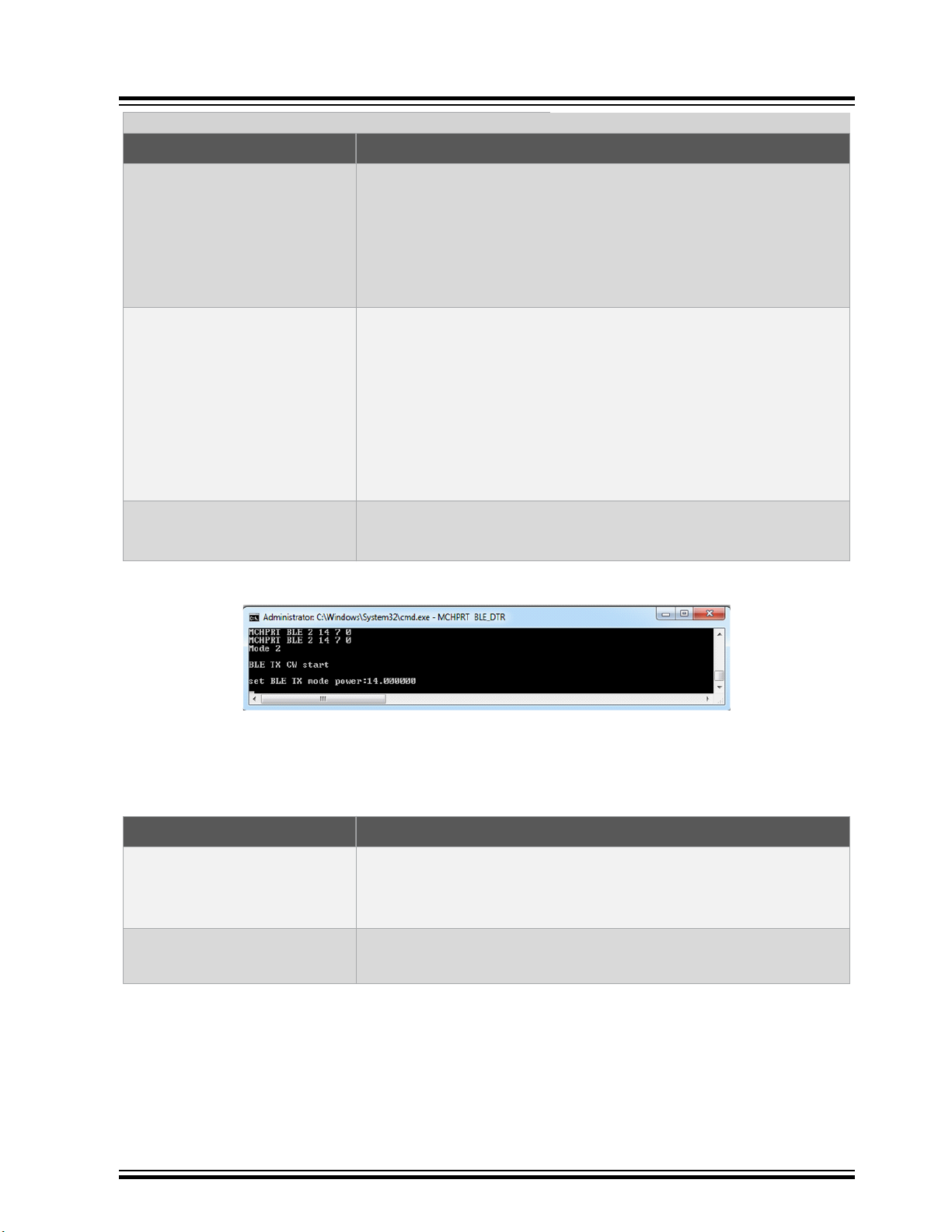
3.3.2.1 CW
The following table provides the command syntax for the BLE TX CW mode.
Table 3-30. Start BLE TX CW: After BLE Initialization with Serial Port
Command Syntax MCHPRT BLE 2 X Y Z A B
X X refer to TX channel: 0 to 39
Y Y refers to Length: 0 – 37
Z Z refers to Payload: 0 – 7
• 0 – Channel 0 (2402 MHz)
• 39 – Channel 39 (2480 MHz)
• 1 – 0x1
• 37 – 0x25
• 0 – PRBS9
• 1 – 11110000
• 2 – 10101010
• 3 – PRBS15
• 4 – 11111111
• 5 – 00000000
• 6 – 00001111
• 7 – 01010101
© 2019 Microchip Technology Inc.
User Guide
DS50002893A-page 69
Page 70

ATWINC/ATWILC/ATSAMB/ATBTLC
...........continued
Command Syntax MCHPRT BLE 2 X Y Z A B
A A refers to Gain:
0: 0x00 1: 0x01 2: 0x02 3: 0x03
4: 0x04 5: 0x05 6: 0x06 7: 0x07
8: 0x08 9: 0x09 10: 0x0B 11: 0x0D
12: 0x11 13: 0x15 14: 0x20 15: 0x3B
B B mean XO offset value (optional): 0-15
0th bit adds 1.25pf
st
1
bit adds 2.5pf
2nd bit adds 5pf
3rd bit adds 5pf
Example: 11 mean 1011 adds a 8.75pf load cap to circuit. Default
value 7 will apply when no input XO offset value
Command Line
Example MCHPRT BLE 2 0 37 1 14
or
MCHPRT BLE 2 0 37 1 14 11
Channel 0. 0x25 length, PRBS9 Gain setting – 0x20 CW mode
The following figure shows the example of BLE CW mode.
Figure 3-37. Console Log of BLE CW Mode
Table 3-31. Start BLE TX CW: After BLE Initialization without Serial Port
Command Syntax MCHPRT BLE 2 X Y Z A B
X X refer to TX channel: 0 to 39
• 0 – Channel 0 (2402 MHz)
• 39 – Channel 39 (2480 MHz)
© 2019 Microchip Technology Inc.
User Guide
DS50002893A-page 70
Page 71
ATWINC/ATWILC/ATSAMB/ATBTLC
...........continued
Command Syntax MCHPRT BLE 2 X Y Z A B
A A refers to Gain:
0: 0x00 1: 0x01 2: 0x02 3: 0x03
4: 0x04 5: 0x05 6: 0x06 7: 0x07
8: 0x08 9: 0x09 10: 0x0B 11: 0x0D
12: 0x11 13: 0x15 14: 0x20 15: 0x3B
B B mean XO offset value (optional): 0-15
0th bit adds 1.25pf
st
1
bit adds 2.5pf
2nd bit adds 5pf
3rd bit adds 5pf
Example: 11 mean 1011 adds a 8.75pf load cap to circuit. Default
value 7 will apply when no input XO offset value
Command Line
Example MCHPRT BLE 2 14 7 0
Figure 3-38. Console Log of BLE CW Mode without Serial Port
3.3.3 BLE RX
The following table provides the command syntax for BLE RX test.
Table 3-32. Start BLE RX: After BLE Initialization with Serial Port
Command Syntax MCHPRT BLE 3 X
X X refers to TX channel: 0 to 39
Example MCHPRT BLE 3 0
Channel 0. 0x25 length, PRBS9 Gain setting – 0x20 CW mode
• 0 – Channel 0 (2402 MHz)
• 39 – Channel 39 (2480 MHz)
Channel 0. RX mode start
The following figure shows the example of start BLE RX test.
© 2019 Microchip Technology Inc.
User Guide
DS50002893A-page 71
Page 72

Figure 3-39. Console Log of BLE RX Mode
3.3.4 BLE RX Packet Count
The following table provides the command syntax for BLE RX packet count.
Table 3-33. Start BLE RX Packet Report: After BLE Initialization with Serial Port
Command Syntax MCHPRT BLE 4
Example MCHPRT BLE 4
ATWINC/ATWILC/ATSAMB/ATBTLC
Command Line
Print out good packet number
The following figure shows the example of BLE RX packet count.
Figure 3-40. Console Log of BLE RX Packet Count
3.3.5 BLE Deinitialization
The following table provides the command syntax for BLE deinitialization.
Table 3-34. BLE Deinitialization: After Initialization
Command Syntax MCHPRT BT 5
Example MCHPRT BT 5
The following figure shows the example of BLE deinitialization.
Figure 3-41. Console Log of BLE Deinitialization
BT Deinitialization
© 2019 Microchip Technology Inc.
User Guide
DS50002893A-page 72
Page 73

3.4 HCI Command
3.4.1 Initialization of COM Port
The following table provides the command syntax for initialization of COM port. Refer to 1.3 UART/I2C
Pin Details to check if DTR is enabled or not.
Table 3-35. Initialization
Command Syntax MCHPRT HCI X
HCI HCI_DTR refers to DTR enable
X X refers to the port number for Bluetooth UART
Example MCHPRT HCI 94
The following figure shows the example of initialization of COM port.
Figure 3-42. Console Log of Initialization of COM Port
ATWINC/ATWILC/ATSAMB/ATBTLC
Command Line
3.4.2 HCI TX
The following table provides the command syntax for the HCI TX test.
Table 3-36. Start HCI TX: HCI command only
Command Syntax MCHPRT HCI 1 X Y Z
X X refer to TX channel: 0 to 39
Y Y refers to Length: 0 – 37
• 0 – Channel 0 (2402 MHz)
• 39 – Channel 39 (2480 MHz)
• 1 – 0x1
• 37 – 0x25
© 2019 Microchip Technology Inc.
User Guide
DS50002893A-page 73
Page 74

ATWINC/ATWILC/ATSAMB/ATBTLC
...........continued
Command Syntax MCHPRT HCI 1 X Y Z
Z Z refers to Payload: 0 – 7
• 0 – PRBS9
• 1 – 11110000
• 2 – 10101010
• 3 – PRBS15
• 4 – 11111111
• 5 – 00000000
• 6 – 00001111
• 7 – 01010101
Example MCHPRT HCI 1 0 37 1
Channel 0. 0x25 length, PRBS9
The following figure shows the example of HCI TX test mode.
Figure 3-43. Console Log of HCI TX Test Mode
Command Line
3.4.3 HCI RX
The following table provides the command syntax for HCI RX test.
Table 3-37. Start HCI RX: HCI command only
Command Syntax MCHPRT HCI 3 X
X X refers to TX channel: 0 to 39
Example MCHPRT HCI 3 0
The following figure shows the example of start HCI RX test.
• 0 – Channel 0 (2402 MHz)
• 39 – Channel 39 (2480 MHz)
Channel 0. RX mode start
© 2019 Microchip Technology Inc.
User Guide
DS50002893A-page 74
Page 75

Figure 3-44. Console Log of HCI RX Mode
3.4.4 HCI RX Package Count
The following table provides the command syntax for HCI RX package count.
Table 3-38. Start HCI RX Package Count: HCI command only
Command Syntax MCHPRT HCI 4
Example MCHPRT HCI 4
ATWINC/ATWILC/ATSAMB/ATBTLC
Command Line
Print out good package number
The following figure shows the example of HCI RX package count.
Figure 3-45. Console Log of HCI RX Package Count
3.4.5 HCI UART Initialization Command
The following table provides the command syntax for HCI UART initialization command.
Table 3-39. Send UART Init Command and Print out Reply
Command Syntax MCHPRT HCI 6
Example MCHPRT HCI 6
The following figure shows the example of HCI UART initialization command.
Figure 3-46. Console Log of HCI UART Init Command
Print out the reply
© 2019 Microchip Technology Inc.
User Guide
DS50002893A-page 75
Page 76

3.4.6 HCI Deinitialization
The following table provides the command syntax for HCI deinitialization.
Table 3-40. HCI Deinitialization: HCI command only
Command Syntax MCHPRT HCI 5
Example MCHPRT HCI 5
The following figure shows the example of HCI deinitialization.
Figure 3-47. Console Log of HCI Deinitialization
ATWINC/ATWILC/ATSAMB/ATBTLC
Command Line
COM port Deinitialization
3.5 Register
3.5.1 Read
The following table provides the command syntax for Reg value read before initialization.
Table 3-41. Reg Value Read: Before Initialization ATWINC/ATWILC
Command Syntax MCHPRT REGR X
REGR • REGR refers to using I2C
X X refers to register number which reads and print value
Example MCHPRT REGR 0
The following figure shows the example of reg value read before initialization.
• REGR_UART refers to using UART
Reg 0 value will be printed
© 2019 Microchip Technology Inc.
User Guide
DS50002893A-page 76
Page 77

ATWINC/ATWILC/ATSAMB/ATBTLC
Figure 3-48. Console Log of Reg Value Read Before Initialization
The following table provides the command syntax for Reg value read after initialization.
Table 3-42. Reg Value Read: After Initialization ATWINC/ATWILC/ATBTLC/ATSAMB
Command Line
Command Syntax MCHPRT 16 REGR X
X X refers to register number which reads and print the value
Example MCHPRT 16 REGR 0
Reg 0 value will be printed
The following figure shows the example of reg value read after initialization.
© 2019 Microchip Technology Inc.
User Guide
DS50002893A-page 77
Page 78

ATWINC/ATWILC/ATSAMB/ATBTLC
Figure 3-49. Console Log of Reg Value Read After Initialization
Command Line
3.5.2 Write
The following table provides the command syntax for Reg value write before initialization.
Table 3-43. Reg Value Write: Before Initialization ATWINC/ATWILC
Command Syntax MCHPRT REGW X Y
REGW • REGW refers to using I2C
X X refers to register number which writes the register location
Y Y refers to write register value which writes the register value
Example MCHPRT REGW 0 8
The following figure shows the example of reg value write before initialization.
© 2019 Microchip Technology Inc.
• REGW_UART refers to using UART
Reg 0 value will change to 8
User Guide
DS50002893A-page 78
Page 79

ATWINC/ATWILC/ATSAMB/ATBTLC
Figure 3-50. Console Log of Reg Value Write Before Initialization
The following table provides the command syntax for Reg value write after initialization.
Command Line
Table 3-44. Reg Value Write: After Initialization ATWINC/ATWILC/ATBTLC/ATSAMB
Command Syntax MCHPRT 16 REGW X Y
X X refers to register number which writes the register location
Y Y refers to write register value which writes the register value
Example MCHPRT 16 REGW 0 8
Figure 3-51. Console Log of Reg Value Write After Initialization
3.5.3 Dump
The following table provides the command syntax for Reg value dump before initialization.
Table 3-45. Reg Value Dump: Before Initialization ATWINC/ATWILC
Command Syntax MCHPRT REGD X Y F
Reg 0 value will change to 8
REGD • REGD refers to using I2C
• REGD_UART refers to using UART
X X refers to register number which reads the register value
Y Y refers to stop register number which reads the register value
© 2019 Microchip Technology Inc.
User Guide
DS50002893A-page 79
Page 80

ATWINC/ATWILC/ATSAMB/ATBTLC
...........continued
Command Syntax MCHPRT REGD X Y F
F F refers to register information file name
Example: test.txt
Example MCHPRT REGD 0 10 test.txt
Report the RX RSSI reading in 10 sec
The following figure shows the example of reg value dump before initialization.
Figure 3-52. Console Log of Reg Value Dump Before Initialization
Command Line
The following table provides the command syntax for Reg value dump after initialization.
Table 3-46. Reg Value Dump: After Initialization ATWINC/ATWILC/ATBTLC/ATSAMB
Command Syntax MCHPRT 16 REGD X Y F
X X refers to register number which reads the register value
Y Y refers to stop register number which reads the register value
F F refers to register information file name
Example: test.txt
Example MCHPRT 16 REGD 0 10 test.txt
Report the RX RSSI reading in 10 sec
The following figure shows the example of reg value dump after initialization.
Figure 3-53. Console Log of Reg Value Dump After Initialization
© 2019 Microchip Technology Inc.
User Guide
DS50002893A-page 80
Page 81

Figure 3-54. Sample test.txt
3.6 eFuse (ATWINC/ATWILC)
For efuse structure refer 8. Appendix E - eFuse and MAC Address
3.6.1 Read
The following table provides the command syntax for read eFuse before initialization.
Table 3-47. Read eFuse: Before Initialization
Command Syntax MCHPRT r
r • r refers to I2C
ATWINC/ATWILC/ATSAMB/ATBTLC
Command Line
• r_UART refers to UART
Example MCHPRT r
eFuse information display
The following figure shows the example of read eFuse before initialization.
Figure 3-55. Console Log of Read eFuse Before Initialization
The following table provides the command syntax for read eFuse after initialization.
© 2019 Microchip Technology Inc.
User Guide
DS50002893A-page 81
Page 82

ATWINC/ATWILC/ATSAMB/ATBTLC
Table 3-48. Read eFuse: After Initialization
Command Syntax MCHPRT 16 r
Example MCHPRT 16 r
eFuse information display
The following figure shows the example of read eFuse after initialization.
Figure 3-56. Console Log of Read eFuse After Initialization
Command Line
3.6.2 Write
3.6.2.1 Write MAC ID Only
The following table provides the command syntax for write MAC ID only.
© 2019 Microchip Technology Inc.
User Guide
DS50002893A-page 82
Page 83

ATWINC/ATWILC/ATSAMB/ATBTLC
Table 3-49. Write MAC ID in eFuse: Before Initialization
Command Syntax MCHPRT XXXXXXXXXXXX or
MCHPRT MAC_UART XXXXXXXXXXXX
MAC_UART • MAC_UART refers to UART
• Without MAC_UART refers to I2C
XXXXXXXXXXXX XXXXXXXXXXXX refers to MAC ID
Example MCHPRT 1234567890AB
eFuse updates the MAC ID: 1234567890AB
eFuse only writes the MAC, remaining information will be copied from
the previous bank.
Example:
Before: BANK 0 MAC 0123456789AB XO offset 1.1
After: Bank 1 MAC 1234567890AB XO offset 1.1
The following figure shows the example of write MAC ID in eFuse.
Command Line
Figure 3-57. Console Log of Write MAC ID for eFuse
3.6.2.2 Write MAC ID Information
The following table provides the command syntax for write MAC ID and frequency offset only before
initialization.
© 2019 Microchip Technology Inc.
User Guide
DS50002893A-page 83
Page 84

ATWINC/ATWILC/ATSAMB/ATBTLC
Table 3-50. Write MAC ID in eFuse: Before Initialization
Command Syntax MCHPRT XXXXXXXXXXXX Y IQ A AE P PE T TEor
MCHPRT MAC_UART XXXXXXXXXXXX Y IQ A AE P PE T TE
MAC_UART • MAC_UART refers to UART
• Without MAC_UART refers to I2C
XXXXXXXXXXXX refers to MAC ID
XXXXXXXXXXXX XXXXXXXXXXXX refers to MAC ID
Y Y refers to frequency offset value
If "XO" is given as input then it disables the XO in eFuse.
A A refers to IQ imbalance amplitude correction value.
Give the value as "0". The current WILC/WINC firmware doesn’t
support this feature, it is for future reservation
If "AMP" is given as input then it disable amplitude imbalance in efuse.
AE AE refers to correction value real or imaginary
0: Real
Command Line
1: Imaginary
If "AMP" is given as input then it disable amplitude imbalance in efuse.
P P refers to phase correction value in IQ imbalance.
Give the value as "0". The current WILC/WINC firmware doesn’t
support this feature, it is for future reservation
If "Phase" is given as input then it disable phase imbalance in efuse.
PE PE refers to correction value real or imaginary
0: Real
1: Imaginary
If "Phase" is given as input then it disable phase imbalance in efuse.
T Temperature calibration value
use temperature calibration calculator to find the temperature
calibration value.
If "TEMP" is given as input then it disables efuse temperature
calibration
TE Temperature calibration enable
0: disable
© 2019 Microchip Technology Inc.
1: enable
If "TEMP" is given as input then it disables efuse temperature
calibration
User Guide
DS50002893A-page 84
Page 85

ATWINC/ATWILC/ATSAMB/ATBTLC
...........continued
Command Syntax MCHPRT XXXXXXXXXXXX Y IQ A AE P PE T TEor
MCHPRT MAC_UART XXXXXXXXXXXX Y IQ A AE P PE T TE
Example MCHPRT 1234567890AB -70 IQ 0 0 0 0 86 1
eFuse update the MAC ID: 1234567890AB Frequency offset:
-70Amplitude correction value 0
Amplitude enableReal
Phase correction value 0
Amplitude enableReal
Temperature calibration value 86
Temperature calibration Enable
The following figure shows the example of write MAC ID in eFuse before initialization.
Figure 3-58. Console Log of Write MAC ID for eFuse Before Initialization
Command Line
The following table provides the command syntax for write MAC ID and frequency offset only after
initialization.
Table 3-51. Write MAC ID and Frequency Offset in eFuse: After Initialization
Command Syntax MCHPRT 20 XXXXXXXXXXXX Y IQ A AE P PE T TE
XXXXXXXXXXXX XXXXXXXXXXXX refers to MAC ID
Y Y refers to frequency offset value
A A refers to IQ imbalance amplitude correction value.
Give the value as "0". The current WILC/WINC firmware doesn’t support
this feature, it is for future reservation.
© 2019 Microchip Technology Inc.
User Guide
DS50002893A-page 85
Page 86

ATWINC/ATWILC/ATSAMB/ATBTLC
...........continued
Command Syntax MCHPRT 20 XXXXXXXXXXXX Y IQ A AE P PE T TE
AE AE refers to correction value real or imaginary
0: Real
1: Imaginary
P P refers to phase correction value in IQ imbalance.
Give the value as "0". The current WILC/WINC firmware doesn’t support
this feature, it is for future reservation.
PE PE refers to correction value real or imaginary
0: Real
1: Imaginary
T Temperature calibration value
Use temperature calibration calculator to find the temperature calibration
value.
TE Temperature calibration enable
0: disable
Command Line
1: enable
Example MCHPRT 20 1234567890AB -70 IQ 0 0 0 0 86 1
eFuse update the MAC ID: 1234567890AB
Frequency offset: -70
Amplitude correction value 0
Amplitude enableReal
Phase correction value 0
Amplitude enableReal
Temperature calibration value 86
Temperature calibration Enable
The following figure shows the example of write MAC ID and frequency offset in eFuse after initialization.
© 2019 Microchip Technology Inc.
User Guide
DS50002893A-page 86
Page 87

ATWINC/ATWILC/ATSAMB/ATBTLC
Figure 3-59. Console Log of Write MAC ID for eFuse After Initialization
Command Line
3.7 efuse ATBTLC/ATSAMB
For efuse structure refer 8. Appendix E - eFuse and MAC Address
3.7.1 Read
Table 3-52. Read eFuse: Before Initialization
Command Syntax MCHPRT BLE r
r r meaning read MAC ID by JLink
Example MCHPRT BLE r
The following figure shows the example of read eFuse before initialization.
Figure 3-60. Console Log of Read eFuse Before Initialization
© 2019 Microchip Technology Inc.
eFuse information display
User Guide
DS50002893A-page 87
Page 88

ATWINC/ATWILC/ATSAMB/ATBTLC
The following table provides the command syntax for read eFuse after initialization.
Table 3-53. Read eFuse: After Initialization
Command Syntax MCHPRT 16 r
Example MCHPRT 16 r
eFuse information display
Command Line
The following figure shows the example of read eFuse after initialization.
Figure 3-61. Console Log of Read eFuse After Initialization
3.7.2 Write
3.7.2.1 Write MAC ID Only
The following table provides the command syntax for write MAC ID only.
Table 3-54. Write MAC ID in eFuse: Before Initialization
Command Syntax MCHPRT BLE XXXXXXXXXXXX
XXXXXXXXXXXX XXXXXXXXXXXX refers to MAC ID
© 2019 Microchip Technology Inc.
User Guide
DS50002893A-page 88
Page 89

ATWINC/ATWILC/ATSAMB/ATBTLC
...........continued
Command Syntax MCHPRT BLE XXXXXXXXXXXX
Example MCHPRT BLE 3334567893AB
eFuse update the MAC ID: 3334567893AB
The following figure shows the example of write MAC ID in eFuse.
Command Line
3.8 Firmware Upgrade
Note: For updating the .bat file please refer to the Firmware update section in the appendix.
3.8.1 ATWINC Series Upgrade
3.8.1.1 Full
The following table provides the command syntax for firmware upgrade.
Table 3-55. Firmware Upgrade: Before Initialization
Command Syntax Upgrade_1500/ Upgrade_3400
X X refers to Antenna
Example Upgarde_1500
The following figure shows the example of firmware upgrade.
• Upgrade_1500 - ATWINC1500 FW upgrade
• Upgrade_3400 - ATWINC3400 FW upgrade
ATWINC1500 FW upgrade starts and when completes it shows
“PASS”
© 2019 Microchip Technology Inc.
User Guide
DS50002893A-page 89
Page 90

ATWINC/ATWILC/ATSAMB/ATBTLC
Figure 3-62. Console Log of Firmware Upgrade
Command Line
3.8.1.2 Gain Table
The following table provides the command syntax for firmware upgrade (gain table).
Table 3-56. Firmware Upgrade (gain table): Before Initialization
Command Syntax Upgrade_1500_Gain/ Upgrade_3400_Gain
X X refers to Antenna
Example Upgarde_1500_Gain
The following figure shows the example of firmware upgrade (gain table).
© 2019 Microchip Technology Inc.
• Upgrade_1500_Gain - ATWINC1500 FW upgrade
• Upgrade_3400_Gain - ATWINC3400 FW upgrade
ATWINC1500 FW upgrade starts and when completes it closes the
command line
User Guide
DS50002893A-page 90
Page 91

ATWINC/ATWILC/ATSAMB/ATBTLC
Figure 3-63. Console Log of Firmware Upgrade (Gain table)
Command Line
3.8.1.3 Provisioning Webpage
The following table provides the command syntax for firmware upgrade (provisioning webpage).
Table 3-57. Firmware Upgrade (Provisioning Webpage): Before Initialization
Command
Syntax
X X refers to Antenna
Example Upgarde_1500_provisioning_webpage
The following figure shows the example of firmware upgrade (provisioning webpage).
Upgrade_1500_provisioning webpage/ Upgrade_3400_provisioning_webpage
ATWINC1500 webpage update
• Upgrade_1500_provisioning_webpage - ATWINC1500
• Upgrade_3400_provisioning_webpage - ATWINC3400
© 2019 Microchip Technology Inc.
User Guide
DS50002893A-page 91
Page 92

ATWINC/ATWILC/ATSAMB/ATBTLC
Figure 3-64. Console Log of Firmware Upgrade (Provisioning Webpage)
Command Line
Note: ASF has the latest firmware. See Firmware upgrade folder in MCHPRT2 package, for information
on how to add the upgrade file into MCHPRT2 tool folder.
Important: Before the Firmware upgrade, update the Firmware file in the following folder:
• ..\MCHPRT\upgrade_1500\firmware\firmware (for ATWINC1500)
• ..\MCHPRT\upgrade_3400\firmware\firmware (for ATWINC3400)
3.8.2 ATWILC Series Upgrade
3.8.2.1 Updating Target Firmware
Before the Firmware upgrade, update the target firmware file in the ATWILC1000 or ATWILC3000 folder:
\..\MCHPRT\upgrade_1000
© 2019 Microchip Technology Inc.
User Guide
DS50002893A-page 92
Page 93

Figure 3-65. Target Firmware File
Note: If required, edit the .csv file for gain table update. For additional details on the gain table update
procedure, refer to the application notes.
3.8.2.2 Gain Table Update
Edit the Upgrade_1000_Gain.bat or Upgrade_3000_Gain.bat. Update the highlighted text (as
shown in the following figure) to update target bin or hex file and then save the edited bat file.
Figure 3-66. Editing Firmware Files
ATWINC/ATWILC/ATSAMB/ATBTLC
Command Line
3.8.2.3 Gain Table Update on Target Firmware
The following table provides the command syntax for gain table update on target firmware.
Table 3-58. Upgrade Gain Table on Target Firmware File
Command Syntax Upgrade_1000_gain/ Upgrade_3000_gain
Setting model • Upgrade_1000_gain - ATWILC1000 FW upgrade
• Upgrade_3000_gain - ATWILC3000 FW upgrade
Example Upgarde_1000_gain
Target file will upgrade with new gain table
The following figures illustrate the example of firmware upgrade.
© 2019 Microchip Technology Inc.
User Guide
DS50002893A-page 93
Page 94

ATWINC/ATWILC/ATSAMB/ATBTLC
Figure 3-67. Console Log of Firmware Upgrade using ATWILC1000
Command Line
© 2019 Microchip Technology Inc.
User Guide
DS50002893A-page 94
Page 95

ATWINC/ATWILC/ATSAMB/ATBTLC
Figure 3-68. Console Log of Firmware Upgrade using ATWILC3000
Command Line
© 2019 Microchip Technology Inc.
User Guide
DS50002893A-page 95
Page 96

ATWINC/ATWILC/ATSAMB/ATBTLC
4. Appendix A - Python® Example
Overview
Python is an interpreted, high-level general-purpose programming language. Refer to https://
www.python.org/ for downloading Python software and documentation.
4.1 Example
3 Tx with 1 Rx test case:
import sys
# import Python standard function for sys
import subprocess
# import Python standard function for call CMD function
import time
# import Python standard function for time
start_time = time.time()
#Python standard function for time check the start time
child = subprocess.Popen(["MCHPRT", "3400"], stdout=subprocess.PIPE,stdin=subprocess.PIPE )
# Start Init in CMD type "MCHPRT 3400" using subprocess
time.sleep(1)
# Delay 1 sec for upload test FW to module
Appendix A - Python® Example
print "Start Test TX1 11b 11Mbps"
# Print the command state to screen
child.stdin.write("MCHPRT 6 6 3 0 0 -10 18 15 1500 0\n")
# Send command to start TX, command informaiton please help to check application note
# add the TX measurement in here
print "Start Test TX2 11g 54Mbps"
# Print the command state to screen
child.stdin.write("MCHPRT 6 6 7 1 0 -10 18 15 1500 0\n")
# Send command to start TX, command informaiton please help to check application note
# add the TX measurement in here
print "Start Test TX3 11n MCS7"
# Print the command state to screen
child.stdin.write("MCHPRT 6 6 7 2 0 -10 18 15 1500 0\n")
# Send command to start TX, command informaiton please help to check application note
# add the TX measurement in here
print "Stop TX"
# Print the command state to screen
child.stdin.write("MCHPRT 13\n")
# Send command to stop TX, command informaiton please help to check application note
print "Test RX1 channel 6"
# Print the command state to screen
child.stdin.write("MCHPRT 2 6\n")
# Send command to start channel 6, command informaiton please help to check application note
print "Test RX1 package count "
# Print the command state to screen
child.stdin.write("MCHPRT 3\n")
# Send command to stop RX and printing recevied package information, command informaiton
please help to check application note
child.stdin.write("MCHPRT 4\n")
# Send command to close MCHPRT, command informaiton please help to check application note
print child.stdout.read()
child.stdin.close()
© 2019 Microchip Technology Inc.
User Guide
DS50002893A-page 96
Page 97

ATWINC/ATWILC/ATSAMB/ATBTLC
child.kill()
print("--- %s seconds ---" % (time.time() - start_time))
#--- 7.08999991417 seconds ---
Figure 4-1. Log when the script is run:
Appendix A - Python® Example
© 2019 Microchip Technology Inc.
User Guide
DS50002893A-page 97
Page 98

ATWINC/ATWILC/ATSAMB/ATBTLC
5. Appendix B - HCI Command Tools
This appendix explains HCI command tools included in the following function for serial port
communication:
• HCI TX command
• HCI RX command
• Serial port communication
– Hexadecimal communication
– Decimal communication
– String communication
Figure 5-1. HCI Command Tool
Appendix B - HCI Command Tools
5.1 HCI Initialization
Perform the following steps for HCI initialization.
1. Click rescan button to scan the serial port in PC.
2. Select the COM Port.
3. Select the Baud Rate.
4. Click Open to open the Serial port for communication.
© 2019 Microchip Technology Inc.
User Guide
DS50002893A-page 98
Page 99

ATWINC/ATWILC/ATSAMB/ATBTLC
Appendix B - HCI Command Tools
Figure 5-2. HCI Command Initialization
5. Select the baud rate as Custom and then DTR is enabled. Select DTR check box.
Figure 5-3. Enable DTR
5.2 HCI Command
After the initialization of the Serial port connection, the button will change to “Close”.
Figure 5-4. Serial Port Initialization
© 2019 Microchip Technology Inc.
User Guide
DS50002893A-page 99
Page 100
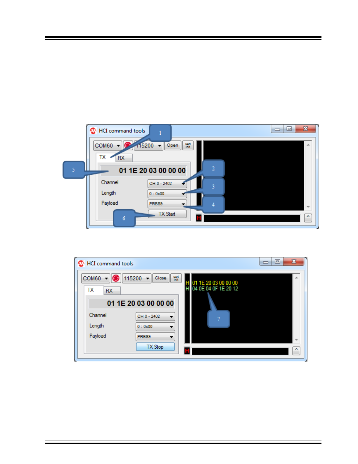
5.2.1 HCI TX
Perform the following steps for TX.
1. After successful initialization, select the TX tab to change to TX HCI command.
2. Select the Channel.
3. Select the Length.
4. Select the Payload.
5. Then the HCI command is shown in the TX command box.
6. Click TX Start to send the TX HCI command.
ATWINC/ATWILC/ATSAMB/ATBTLC
Appendix B - HCI Command Tools
Figure 5-5. Start TX
7. The sent and received HCI command is shown in the log. Yellow represents the sent command
[Hex] and Green represents the received command [Hex].
Figure 5-6. Sent/Received HCI Command
8. Click TX Stop to send TX stop command.
© 2019 Microchip Technology Inc.
User Guide
DS50002893A-page 100
 Loading...