

Page 1
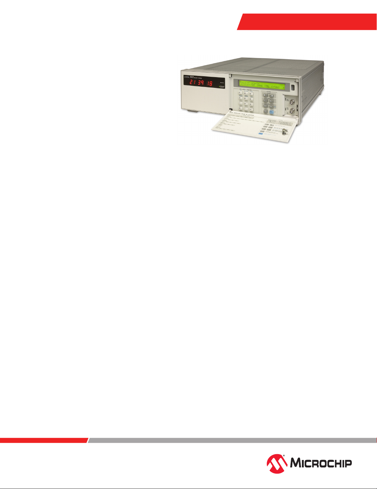
5071A
Primary Frequency Standard
Features
• Easy to use with automatic startup and
intuitive menu structure
• Fast warm up ±5.0 x 10
minutes or less for high-performance tube
• Integrated clock and message displays
• Multiple timing and frequency inputs and
outputs with easy access at front and rear
• Automatic synchronization of 1PPS signal
• Remote interface and control including
alarm output
• Meets requirements in the new ITU-T
G.811.1 ePRC standard
Benets
• Maintains exceptional accuracy and
stability even in unstable environments—
unsurpassed stability in the lab or eld
• Accuracy ±1.0 x 10
mance; ±5.0 x 10
• Stability ≤1.2 x 10
mance; ≤5.0 x 10
(for 1 second averaging time)
• Environmental stability ±1.0 x 10
standard performance; ±8.0 x 10
high performance (frequency change
for any combination of environmental
conditions)
• Long-term stability ≤5.0 x 10
dard performance; ≤1.0 x 10
performance (for 5-day averaging time)
• Proven reliability with an average mean
time between failures (MTBF) of greater
than 160,000 hours
• Full traceability to NIST
• AC and DC input and internal battery
back-up
–13
accuracy in 30
–12
for standard perfor-
–13
for high performance
–11
for standard perfor-
–12
for high performance
–13
for
–14
for
–14
for stan-
–14
for high
The 5071A primary frequency standard
has the accuracy and stability you need
for both laboratory and eld applications.
A stability specication for 30-day aver-
aging time means the 5071A will keep
extremely predictable time and phase
for long periods. Further, the 5071A can
be used for long-term averaging of noisy
signals such as GPS.
The 5071A is easy to use. No more
manual start-up steps or complicated
adjustments—everything is automatic.
A logical menu structure simplies front
panel operations, selections, and status
reporting. Remote control features tailor
the 5071A for complete operation and
manageability in virtually any location.
The instrument is a direct descendant of
and replacement for the veteran 5060A,
5061A, and 5061B cesium standards.
This innovative product is the result of
more than 35 years of experience in the
precision frequency standard business.
Frequency and Timing
Meeting the Needs of LeadingEdge Metrology and Calibration
Labs
Timekeeping and National Standards
Laboratories verify the stability and accuracy of their in-house cesium standards
to Coordinated Universal Time (UTC),
provided by the Bureau International
des Poids et Mesures (BIPM) in Paris.
A standard’s accuracy and reliability
determine the quality of service these
timekeeping labs provide. Of even greater
concern is the stability of a standard.
Stability directly aects a laboratory’s ability to deliver timekeeping and calibration
services to its clients.
The 5071A oers exceptional stability
and is the rst cesium standard to specify
its stability for averaging times longer
than one day. The instrument takes into
account environmental conditions that
can heavily inuence a cesium standard’s
long-term stability. Digital electronics
continuously monitor and optimize the
instrument’s operating parameters.
Thus, the 5071A’s response to environmental conditions such as temperature
and humidity are virtually eliminated.
The 5071A primary frequency standard
maintains its accuracy and stability, even
in unstable environments.
www.microchip.com
Page 2

Satellite Communications
Stable frequency generation is required to transmit and
receive signals properly between ground terminals and
communication satellites. Frequency exibility is also needed
to adjust for satellite-to-satellite carrier-frequency dierences.
The 5071A’s state-of-the-art technology produces oset and
primary frequencies with the same guaranteed stability.
Exceptional Accuracy
The intrinsic accuracy of the improved cesium beam tube
(CBT) assures that any high performance 5071A will power up
to within ±5.0 x 10
This is achieved under full environmental conditions in 30
minutes or less, and without the need for any adjustments or
alignments.
–13
of the accepted standard for frequency.
For secure communications, precise timing synchronization ensures that encrypted data can be recovered quickly.
Frequency-agile signals also require exact synchronization
between transmitter and receiver during channel hops.
The 5071A automates the synchronization to any external
1PPS signal, greatly simplifying this aspect of satellite
communications.
The 5071A and GPS
The 5071A primary frequency standard can work very well
with a GPS timing receiver to produce and maintain highly
accurate time and frequency.
The GPS system provides accurate time, frequency, and
location information worldwide by means of microwave radio
broadcasts from a system of satellites. Timing accuracy for
the GPS system is based, in large part, on the accuracy and
stability of a number of 5071A primary frequency standards.
These standards are maintained by the GPS system, the US
Naval Observatory, and various timing laboratories around the
world that contribute to UTC, the world time scale.
Because of their accurate time reference, GPS signals
processed by a good GPS timing receiver can provide highly
accurate time and frequency outputs. However, since GPS
receivers rely on very low level microwave signals from the
satellites, they sometimes lose accuracy because of interfering
signals, local antenna problems, or bad satellite data.
In spite of these problems, a GPS timing receiver can be an
excellent backup and reference to a local 5071A primary
frequency standard. The GPS receiver provides an independent reference that can be used to verify the accuracy of a
caesium standard, or it can be used as a temporary backup
should the cesium standard need repair. The local 5071A
standard has better stability, better output signal quality, and is
not perturbed by interfering signals, intermittent signal loss, or
bad satellite data.
With these characteristics, the synergy created by combining a good quality GPS timing receiver and a 5071A primary
frequency standard can produce a highly robust, inexpensive,
and redundant frequency and time system.
Unsurpassed Stability
The 5071A high-performance cesium beam tube guarantees
stability to be better than 1.0 x 10
ve days or greater. The 5071A is the rst cesium standard
to specify stability for averaging times longer than 1.0 x 10⁵
seconds (approximately one day).
The 5071A is also the rst cesium standard to specify and
guarantee a icker oor. Flicker oor is the point at which the
standard’s stability (σy (2, τ)) does not change with longer
averaging. The high performance 5071A icker oor is guar-
anteed to be 1.0 x 10
–14
or better. Long-term measurements
at the National Institute of Standards and Technology (NIST)
show that the icker oor is typically better than 5.0 x 10
Unstable environments are normal for many cesium standard
applications. The 5071A features a number of microprocessor controlled servo loops which allow it to virtually ignore
changes in temperature, humidity, and magnetic elds.
The 5071A delivers exceptional performance over very long
periods of time, greatly increasing the availability of critical
time and frequency services. Actual measurements made
at NIST have demonstrated that a 5071A with the highperformance CBT will drift no more than 5.0 x 10
entire life of the CBT.
–14
for averaging times of
–14
over the
–15
.
Traditional Reliability
The 5071A has demonstrated an average mean time between failures (MTBF) of greater than 160,000 hours since its
introduction in 1992. This data is based on actual eld repair
data. Backing up this reliability is a 10-year warranty on the
standard long-life cesium beam tube and a 5-year warranty
for the high performance tube.
Complete repair and maintenance services are available at our
repair center in Beverly, Massachusetts.
Full Traceability to NIST
Microchip provides NIST traceability to the accuracy measurements made on every 5071A. Traceability to NIST is maintained
through the NIST-supplied Time Measurement and Analysis
System (TMAS). This service exceeds the requirements of
www.microchip.com
Page 3

MIL-STD-45662A and can be a valuable tool in demonstrating
traceability to your customers.
Straightforward Operation
Internal microprocessor control makes start-up and operation of
the 5071A extremely simple. Once connected to an AC or DC
power source, the 5071A automatically powers up to its full accu-
racy specications. No adjustments or alignments are necessary
during power-up or operation for the life of the cesium tube.
An intuitive menu structure is accessible using the front panel
LCD display and keypad. These menus—Instrument State, Clock
Control, Instrument Conguration, Event Log, Frequency Oset
and Utilities—logically report status and facilitate control of the
instrument. These functions are described as follows.
Instrument State
Overall status is displayed, including any warnings in eect. Key
instrument parameters such as C-eld current, electron multiplier
voltage, ion pump current, and cesium beam tube oven voltage
are available. You can initiate a hard copy report of this data on
your printer with the push of a button.
Clock Control
Set the time and date, schedule leapseconds, adjust the epoch
time (in 50 ns steps), and automatically synchronize the 1PPS
signal to within 50 ns of an external pulse using this menu.
Instrument Conguration
Set the instrument mode (normal or standby) and assign frequencies (5 MHz or 10 MHz) to the two independently program-
mable output ports; congure the RS-232C data port.
High-Performance Cesium Beam Tube
The 5071A high performance cesium beam tube is optimal for
the most demanding operations. The high-performance tube
oers a full-environment accuracy specication of ±5.0 x 10
–13
—two times better than the specication for the standard tube.
Stability is also signicantly improved. The high-performance
tube reaches a icker oor of 1.0 x 10
–14
or better, and long-
term measurements at NIST show that the icker oor is
typically better than 5.0 x 10
–15
.
Integrated Systems and Remote Operation
Today, cesium standards are often integrated into telecommunication, satellite communication, or navigation systems as
master clocks. To accommodate these environments, the 5071A
provides complete remote control and monitoring capabilities. Instrument functions and parameters can be interrogated
programmatically.
Communication is accomplished using the standard commands
for programmable instruments (SCPI) language and a dedicated
RS-232C port. Also, a rear panel logic output can be pro-
grammed to signal when user-dened abnormal conditions exist.
For uninterruptible system service, an internal battery provides
45 minutes of backup in case of AC power failure. Thus,
the 5071A can be managed easily even in the most remote
locations.
Event Log
Signicant internal events (power source changes, hardware
failures, warning conditions) are automatically recorded with the
time and date of their occurrence. A single keystroke produces a
hard copy on your printer for your records.
Frequency Oset (Settability)
Output frequencies may be oset by as much as 1.0 x 10⁻⁹
in steps of approximately 6.3 x 10
–15
. All product stability and
output specications apply to the oset frequency.
Utilities
The rmware revision level and cesium beam tube identication
information can be displayed.
www.microchip.com
Page 4

Specications
Electrical
Frequency Outputs (4)
[1] 100 kHz and
Frequency
Format
Amplitude
Harmonic
Non-harmonic
Connector
Load Impedance
Location
Isolation Between Ports
Timing Outputs (3) 1PPS
Format
Amplitude
Pulse Width
Rise Time
Jitter
Connector
Load Impedance
Location
Sync input
Amplitude
Pulse Width
Rise time
Jitter
Connector
Load Impedance
Location
Manual Sync
Range
Resolution
Auto Sync
1
Each output can be set to either 5 MHz or 10 MHz from the front panel or by remote control.
[2] 5 MHz, 10 MHz
Sine Sine
≥1 Vrms ≥1 Vrms
≤–40 dBc ≤–40 dBc
≤–80 dBc
N BNC
50 Ω 50 Ω
Rear panel Rear panel
≥110 dB (typical)
1PPS
≥2.4 V into 50 Ω (TTL compatible)
20 μs
≤5 ns (slew rate >10–9 volt/second at 1.5 V)
≤1 ns rms
BNC
50 Ω
One front panel
Two rear panel timing outputs
(2) 1PPS
(Each may be independently armed)
2 V—10 V max
100 ns min to 100 μs max
≤50 ns
≤1 ns rms
BNC
50 Ω
One front panel
One rear panel
+/–0.5 s
50 ns
+/–50 ns
1
[1] 1 MHz
General Environment
Temperature
Operating
Non-operating
Humidity
Magnetic Field
Atmospheric Pressure
Shock and Vibration
EMI/EMC
UL Safety
AC Power Requirements
Operating Voltage
Power
Operating
Warm-up
DC Power
Requirements
Power
Operating
Warm-up
Internal Standby Battery
Capacity
Charge Time
Charge source
Dimensions/weight
Height
Width
Depth
Weight
MTBF
0 °C—55 °C
–40 °C—70 °C
0 to 95% RH (45 °C max)
DC, 55, 60 Hz 2 gauss
Peak—Any Orientation
≤1.0 × 10
pressure down to 19 kPa (Equivalent to an
altitude of 12.2 km)
–13
change in frequency for
• Shipboard Vibration MIL-STD-167-1,
Paragraph 5.1.2.4.3
• Random Vibration MIL-PRF-28800F,
Paragraph 3.8.4.1 for Class 3 units (2.06
grms 5-500 Hz for 10 min/axis, 3 axes)
• Hammer Blow Shock Test, MIL-S-901C,
Grade A, Class 1, Type A
• Seismic Testing in accordance with
ASCE 7-10 Section 13.2.5. Will maintain
containment of Cesium metal (CAESIUM
UN1407) after testing to ICC-ES AC 156.
• FCC Part 15 Subpart B Class A
• KN61000-6-3 Radiated/Conducted
Emissions
• EN55011 Conducted Emissions
• KN/EN61000-3-2, -3 (AC)
• EN61000-4-4, -5, -6, -11
• KN61000-6-1 Immunity Tests
• KN61000-6-1, -3 (48VDC)
IEC 61010-1:2010 (Third Edition)
100, 120 VAC ±10%, 45 Hz—440 Hz
220, 240 VAC ±10%, 45 Hz—66 Hz
50 W (Standard Performance)
58 W (High Performance)
100 W
22 VDC—42 VDC
45 W (Standard Performance)
50 W (High Performance)
85 W
45 minutes from full charge
16 hours max from fully discharged state
AC input power supply
133.4 mm
425.5 mm
523.9 mm
30 kg
>160,000 hours
www.microchip.com
Page 5

Remote System Interface and Control
RS-232-C (DTE conguration)
Complete remote control and interrogation of all instrument
functions and parameters
Specication
Software
Command Set
Connector
Location
Alarm (TTL)
Output
Circuit is TTL open collector with internal pull-up resistor. Circuit can sink
up to 10 mA.
Standard Commands for Programmable
Instruments (SCPI), version 1990.0 adapted for
RS-232C
9-pin male rectangular D subminiature type
Rear panel
BNC
TTL High, Normal
TTL Low, Fault
Stability (Allan Deviation)
Average Time (s)
0.01 ≤7.5 × 10
0.1 ≤1.2 × 10
1 ≤1.2 × 10
10 ≤8.5 × 10
100 ≤2.7 × 10
1,000 ≤8.5 × 10
10,000 ≤2.7 × 10
100,000 ≤8.5 × 10
5 days ≤5.0 × 10
30 days ≤5.0 × 10
Flicker oor: Guaranteed
Typical
Standard
Performance
≤5.0 × 10
≤1.5 × 10
High Performance
–11
–11
–11
–12
–12
–13
–13
–14
–14
–14
–14
–14
≤7.5 × 10
≤1.2 × 10
≤5.0 × 10
≤3.5 × 10
≤8.5 × 10
≤2.7 × 10
≤8.5 × 10
≤2.7 × 10
≤1.0 × 10
≤1.0 × 10
≤1.0 × 10
≤5.0 × 10
–11
–11
–12
–12
–13
–13
–14
–14
–14
–14
–14
–15
Accuracy and Long-term Stability
2
Specication
Conditions (any combination of)
Temperature
Humidity
Magnetic Field
Shock and vibration
0 °C–50 °C
0 to 85% (40 °C max)
DC, 55, 60 Hz, 2G peak any orientation
100-mm drop
Accuracy
Standard performance
High performance
±1.0 × 10
±5.0 × 10
–12
–13
Frequency Change vs. Environment
Standard performance
High performance
Warm-up time (typical)
Reproducibility
±1.0 × 10
±8.0 × 10
30 minutes
±1.0 × 10
–13
–14
–13
Settability
Range
Resolution
Control
2
Lifetime accuracy (high performance CBT only) after a minimum two-month warm-up. Change no
more than 5.0 × 10
–14
for the life of the CBT.
±1.0 × 10
6.3 × 10
Through RS-232 port
–9
–15
SSB Phase Noise
Oset (Hz) 10 MHz Output 5 MHz Output
1 ≤–100 dBc/Hz ≤–106 dBc/Hz
10 ≤–130 dBc/Hz ≤–136 dBc/Hz
100 ≤–145 dBc/Hz ≤–145 dBc/Hz
1,000 ≤–150 dBc/Hz ≤–150 dBc/Hz
10,000 ≤–154 dBc/Hz ≤–154 dBc/Hz
100,000 ≤–154 dBc/Hz ≤–154 dBc/Hz
Ordering Information
Part Number Description
5071A-C001
5071A-C002
5071A-C007
5071A-C008
High-performance tube
Standard performance tube
High-performance tube with 48 VDC option
Standard performance tube with 48 VDC option
The Microchip name and logo and the Microchip logo are registered trademarks of Microchip Technology Incorporated in the U.S.A. and other countries. All other trademarks mentioned herein are property of their respective
companies.
© 2019, Microchip Technology Incorporated. All Rights Reserved. 4/19 900-00510-000 Rev J
DS00002980B
www.microchip.com
 Loading...