

WORKSHOP TECHNICAL MANUAL
MICROCAR

2
INTRODUCTION
This manual has been made to help you in the repairing and maintenance
operations. It contains all the details about the car and the indications for the fitting
and unfitting.
We advice you to read very carefully the paragraphes linked to your interventions.
Our After Sales department stays at your disposal for any further information.
With the aim of improving its models, MICROCAR specifies this whole brochure is not contractual
and keeps the right to change (without warning) its car specifications.
Concept / ATTRAITSGRAPHIC 05 49 71 20 62

3
SUMMARY
Pages
SUPPLYING .................................................... 4
IDENTIFICATION ............................................ 5
LIFTING ........................................................... 5
TECHNICAL CHARACTERISTICS ........... ......6
D...OOR REMOVAL..............................................8
INTERIOR DOOR MAINTENANCE ................... 9
REAR DOOR ......................................... ..........14
FRONT BUMPERS REMOVAL.................. ......19
FRONT WINGS REMOVAL..............................20
DOOR HINGES REMOVAL............................. 22
BONNET REMOVAL ...................................... 22
OPTI .C LIGHTS REMOVAL............................ 22
BACK BUMPERS REMOVAL ........................ 23
HATCHBACK OPENING SWITCH REMOVAL.24
INTERIOR TRIM REMOVAL........................... 25
SAFETY BELT RETRACTOR REMOVAL..... 27
TR .IM ROOF CHANGING............................... 27
D . ASHBOARD REMOVAL............................... 29
R EVERSER LEVER REMOVAL.................... .35
R . EAR QUARTER PANEL REMOVAL........... 36
B ACK WING REMOVAL ................................ 37
WINDSCREEN REMOVAL...............................42
ROOF REMOVAL ........................................... 44
B ..ODY SIDE REMOVAL................................. 46
SOU ..NDPROOFING FLOOR KIT GLUING.... 50
SOUNDPROOFING KIT APRON GLUING..... 51
ABS REPAIRING............................................. 52
ALUMINIUM REPAIRING ............................. 53
FLOOR REPAIRING ...................................... 54
CARPET REPAIRING .................................... 55
Pages
P . AINTING COMPONENTS AND REPAIRING...... ..56
SO UNDPROOFING ENGINE PANEL REMOVAL... 58
TR ANSMISSION REMOVAL.................................... 60
TRANSMISSSION GAITER CHANGING................................ 61
VARIATO R REMOVAL ............................................ 62
RECEPTOR PULLEY REMOVAL............................. 66
RE. VERSER DRIVE AXLE REMOVAL....................... 68
RE ..VERSER DRIVE AXLE BOX REMOVAL............... 71
S TARTER REMOVAL .............................................. 74
ENGINE REMOVAL ................................................. 75
ENGINE CRADLE REMOVAL................................. 76
ENGINE . CRADLE EQUIPEMEMENT...................... 78
BR .AKE PAD REPLACING....................................... 88
FR ONT HUB BEARING REPLACING ..... .............................90
FRON T HUB BEARING REPLACING .................................94
STEERING............................................................... 96
B RAKING SYSTEM BLEEDING ....................... ......99
P ARKING BRAKE REGULATING ....................... 100
BACK EXHAUST ................................................... 101
E LECTRIC SYSTEM ............................................ 102
FUSES ................................................................... 103
LO AD VOLTAGE CONTROL ................................ 104
F RONT WINDSCREEN ......................................... 105
INSTRUMENT ADJUSTMENT .........................107
VENTILATION CONNECTING .............................. 108
ENCLOSED ........................................................... 109
ELECTRIC PLANS
TECHNICAL INFORMATION N° 247
TECHNICAL INFORMATION N° 249

4
SUPPLYING
Engine oil
Box oil
Brake liquid
Coolant
liquid
Windscreen washer
QUANTITIES
1,50 liter
0,50 liter
3 liters
The level in the
radiator must be 1cm
above the radiator fins
1 liter
SUPPLYING TYPE
CERAMIC SYMBOL 5W40
TRANS EPA 80W90
DOT 4 blue ribbon
TRANSFLUID
Windscreen washer IGOL
5
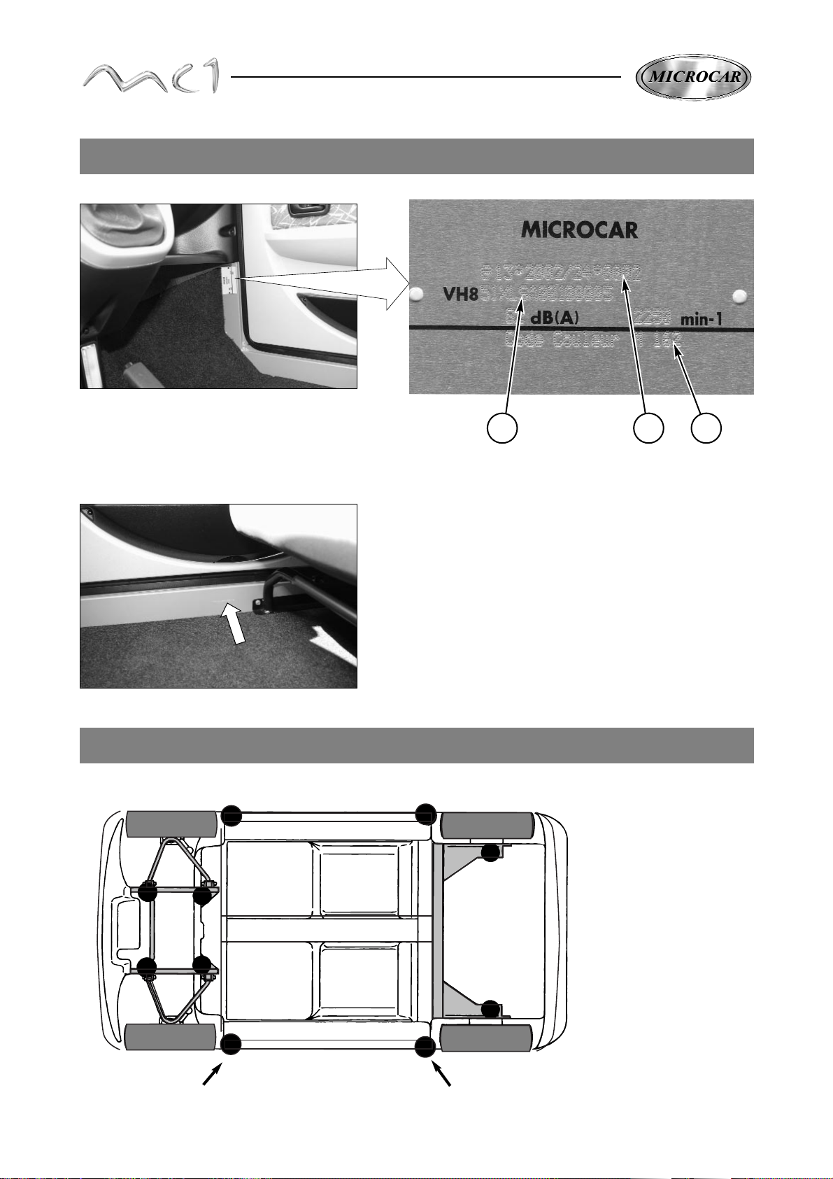
LIFTING
CAR IDENTIFICATION
With a workshop jack, use only the lifting points as shown below.
NOTA : Take care to insert
a wood block between the
jack and the car.
FRONT :
Under the carcase of the body
BACK
Under the carcase of the body
Constructor plate
The constructor plate is situated inside the car
on the front right pillar (under the instrument
panel below the passenger seat).
1-Vin number
2-Homologation number
3-Painting reference number
vin number
The vin number is put on the right side member
near the passenger seat.
1 2 3

6
Engine
Brand ............................................................................ LOMBARDINI
Type ................................................................................ LDW 502/M3
Cycle ............................................................................... Diesel (4 times)
Cubic capacity......................................................................... 505 cm
3
Cylinders ............................................................................. 2 in lines
Coolant ........................................................................... Liquid
Used fuel ......................................................................... Diesel
Feed type ........................................................................ Injection (electric pump)
Fuel tank capacity ........................................................... 16 liters
Electric feed ................................................................... Alternator
Movement transmission
Gearbox with continual variation automatic transmission with reverse and forward gear.
Automatic centrifugal clutch.
Maximum speed authorized.
Suspension
Double action, hydraulic shock absorbers with front and back helical springs
Direction
Direction type : rack (without maintenance)
Steering diameter :8.20m
Braking
Service brake : hydraulic double circuit which acts on front and back wheels
Parking brake : mechanical, it acts on the 2 back wheels
Wheels
Sizes : 145/60R13 65S
Wheels pressure: Front = 1,6 bar.
Back = 1,8 bar.
Body
Carcase in aluminium mechanical soldered profiles
Floor and apron in SANDWIFORM cellular composite panels
ABS trim
Weight and size
Discharged weight : 348 kg.
Running weight : 400 kg.
Total athorized loaded weight : 620 kg.
TECHNICAL CHARACTERISTICS
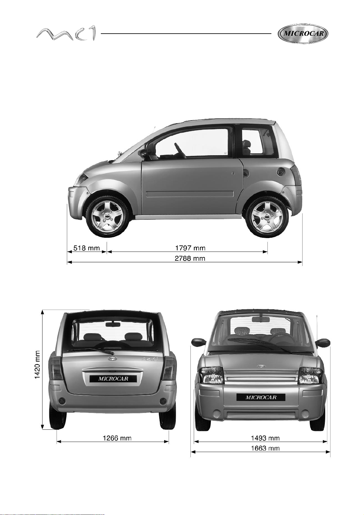
7
SIZES : (in mm)
8
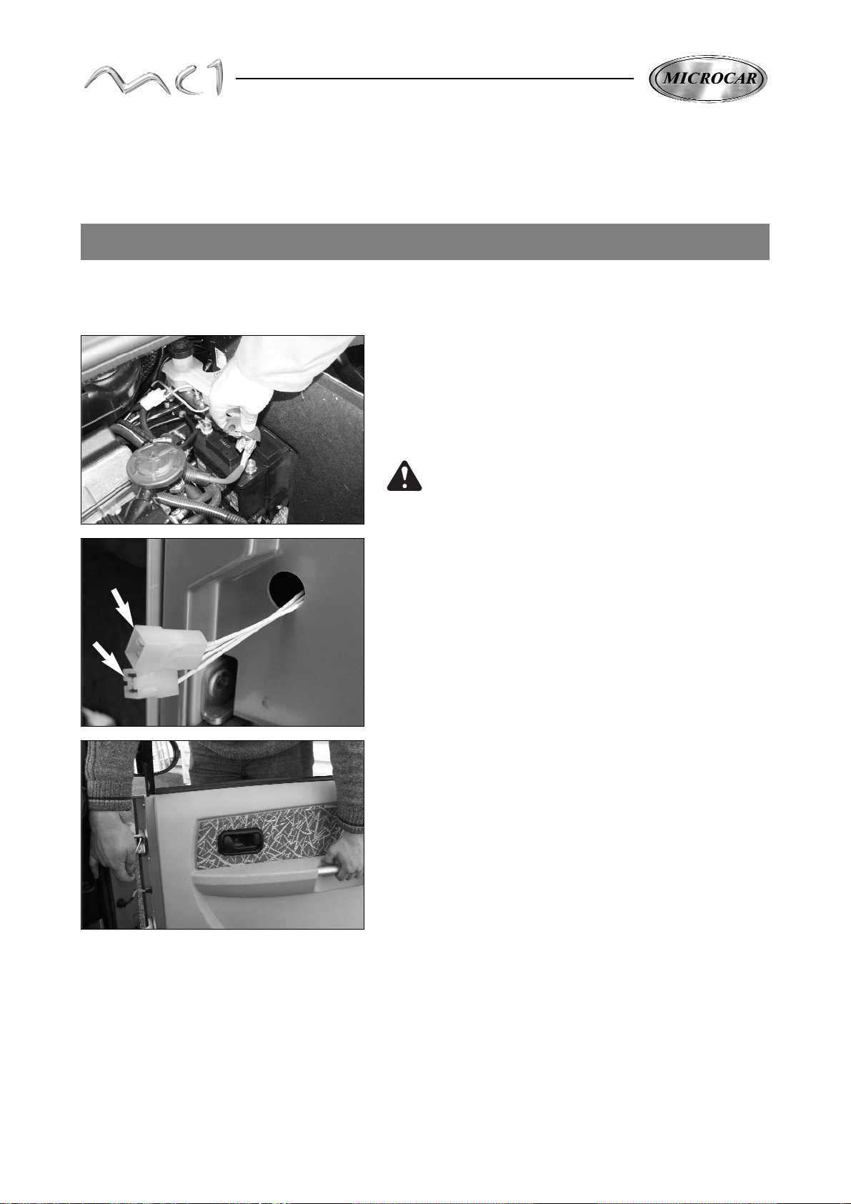
To take out the door, open the bonnet and unplug
the battery using the red speed disconnecting cable terminal
(+).
Take off the ducts of the body pillar, take out and unplug
the 2 connectors of the window winder beam and central locking
✱ .
✱ It depends on the version
DOOR REMOVAL
Hold the door with the handle and put the 2 fixing screws
of the hinges.
(Set screw 7 N/m)
The fitting of the door is made at the reverse from the
removal operations.
Before intervening on any components of the
electric setting, unplug the positive cable (red)
of the battery.
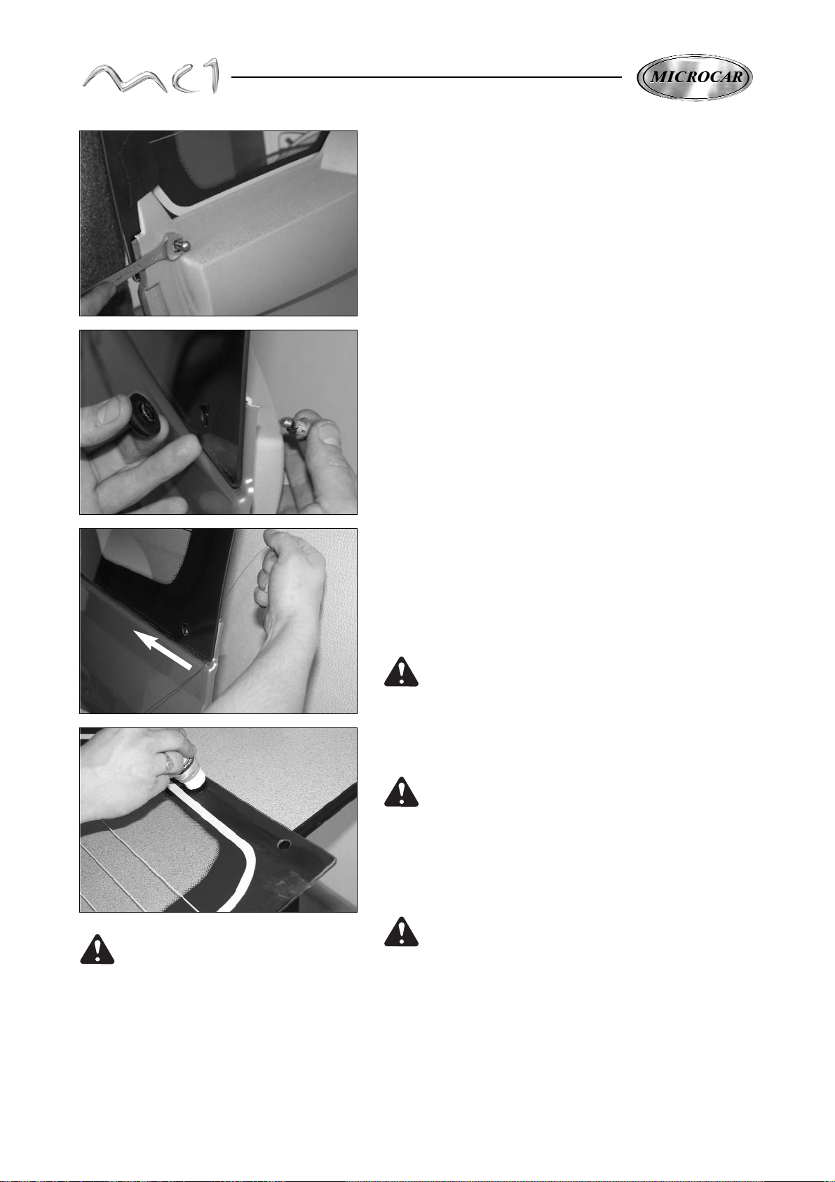
9
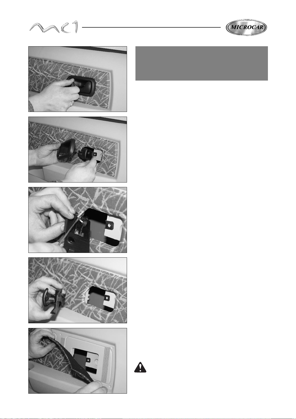
Take the fixing screw out of the interior door opening
switch.
INTERVENTIONS
ON THE INTERIOR DOOR
EQUIPEMENTS
Take out the cap of the handle.
With a screwdriver, unclip the opening tip on the
handle.
Take out the command.
Take off the trim starting in a conner
(fixed with a VELCRO strip)
We advice you to hold the sticker VELCRO
to avoid that it comes undone.
10
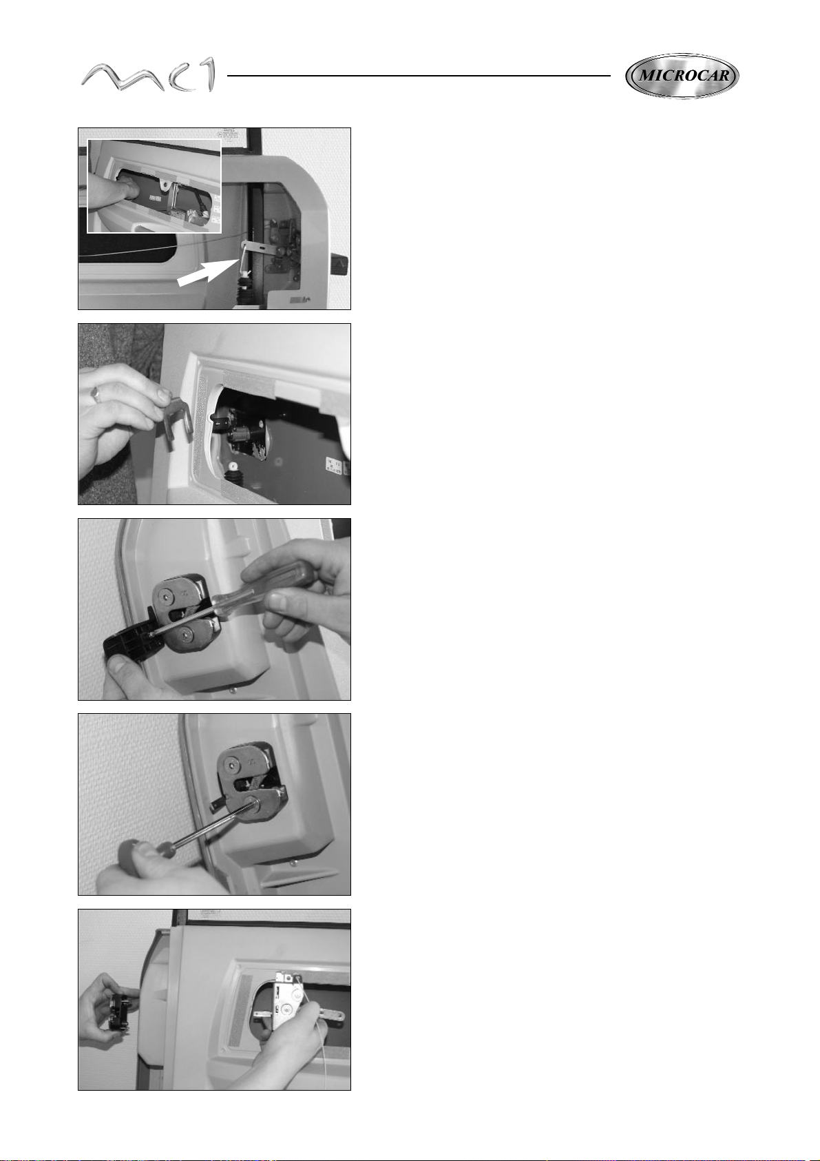
Take out the interior and exterior lock.
With a cuciform screwdriver, unscrew the fixing screw and take off
the plastic handle.
Take out the 2 fixing screws of the exterior lock
(key 6 sections).
LOCK AND CYLINDER LOCK DOORS
NOTA :to make the following operations easier, we advice
you to take the door out.
(see chapter "door removal" page 8)
Take out the central locking rod inside the door.
Take out the cylinder lock, pulling up its fixing fork and taking
off the cylinder lock from its place.
11
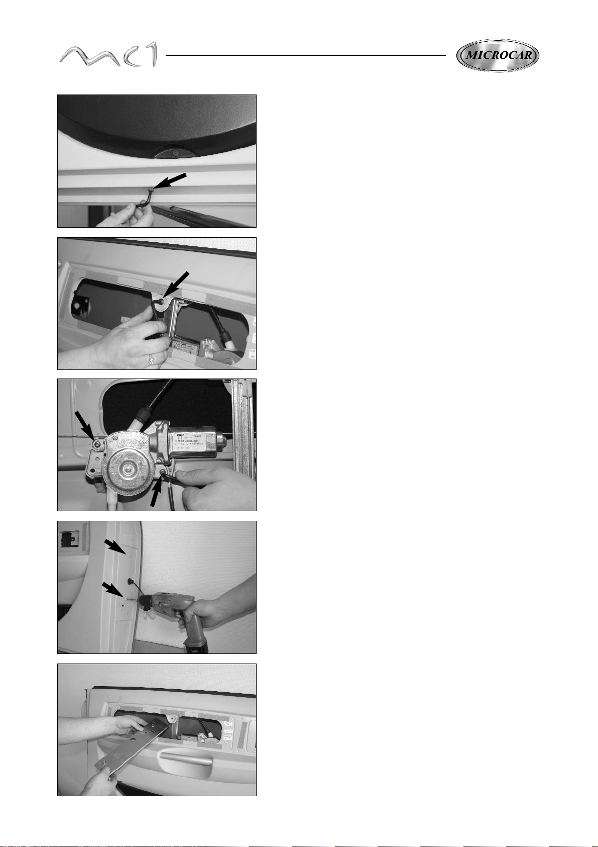
CENTRAL LOCKING ENGINE
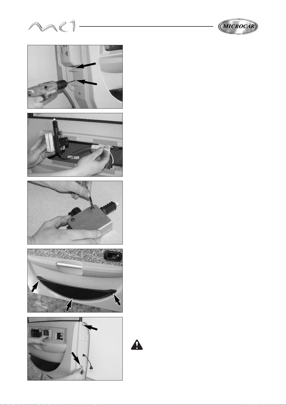
Tha nks to a drilling machine (drill Ø 5) take out the 2 rivets of
the fixing of the central locking engine mounting plate.
Take out the plate and engine and unplug the electric
beam.
Take off the 2 engine fixing screws.
DOOR POCKET
Withe a screwdriver, take off the 3 black plastic rivets
and take out the door pocket.
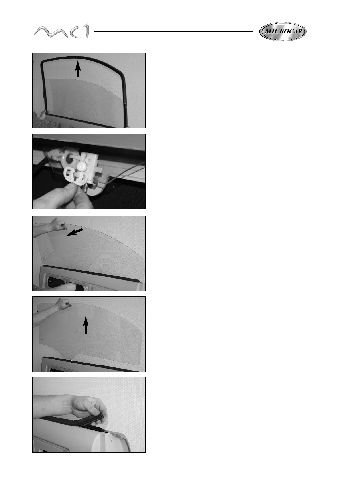
DOOR WINDOW
Take out the 4 fixing screws of the door frame, 2 screws at the front
and 2 at the back.
To take out the door window, it is better that it goes up
at the maximum.
12
Lean slightly the window of the interior of the door
to take it out of the fixing axle.
Take out the window pulling it up.
Take off the joints.
Take out the door frame pulling it up.
Undo the fixing axle of the window.
13
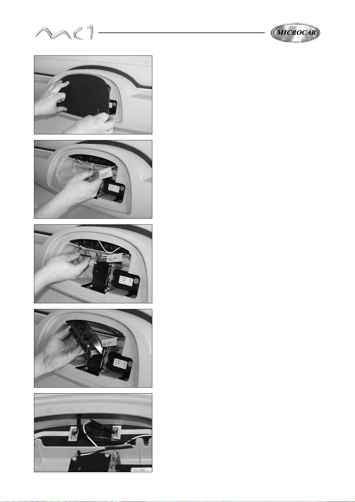
ELECTRIC WINDOW WINDER
Take out the inferior fixing screw of the
window winder runner.
Take out the superior fixing screw of the window winder runner.
Take off the 2 screws of the window winder engine.
Unplug the electric beam and take out the window winder
of the interior door.
HINGE REINFORCEMENT PLATE
With a drilling machine (drill Ø 5) take out the 2 fixing rivets
of the hinge reinforcement plate.
Take off the beam and take out the plate.
All the reassembly operations of the interior door elements are made at the
reverse from the removal operations.

14
REAR DOOR
REAR DOOR REMOVAL
Unplug the battery using the red speed disconnecting cable
terminal (+).
Remove the ball joints of the 2 gas compass.
Take off the hatchback.
The fitting of the hatchback has to be made at the reverse from
the removal operations.
3rd PARKING LIGHT
After having unplugged the battery, take out the 2 fixing screws
of the hatch of the rear window.
Open the hatchback.
Unplug the hatchback electric beam, behind the right side
trim and take it out of the trim.
Hold the hatchback and take off the 2 fixing screws of the
hinges on the body.
Nota: When fitting again, for a perfect waterproofness, put some
silicone joint in the places of the hinges fixing screws.
15
Take off the hatch.
Unplug the beam of the 3d parking light.
Take out the 2 fixing screws of 3d parking light.
Take off the 3d parking light.
After having taken out the 3d parking light, you will be able to
reach the defrosting back window beam.
NOTA : The electric beam inside the hatchback can't be dismantled,
it is assembled first in the factory.
16
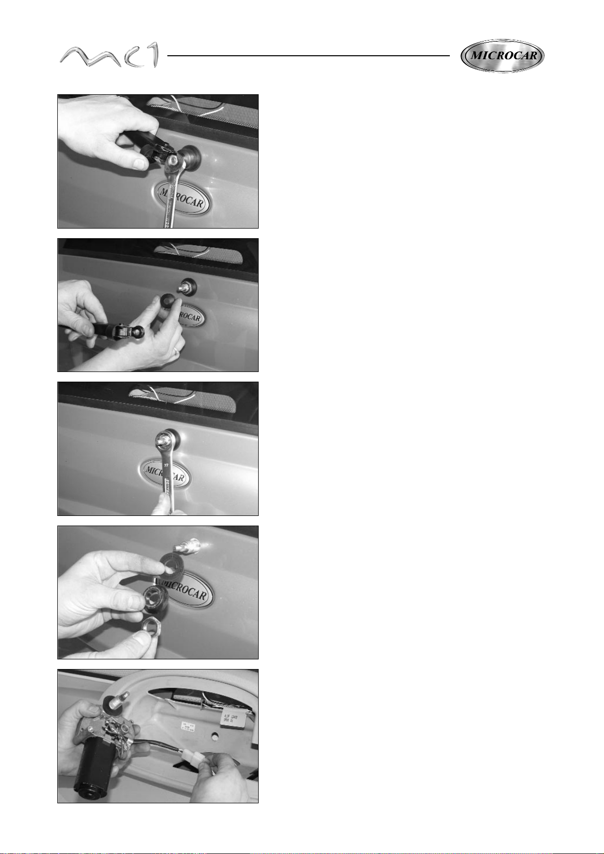
BACK WINDSCREEN WIPER
After having unplugged the battery and taken out the hatch of
the back window (see paragraph "3d parking light" page 14)
take out the fixing nut of the wiper arm under the nut cover.
Take out the wiper arm and the nut cap.
Take out the M16 fixing nut of the windscreen wiper engine.
Take out the spacer and washer.
Take out the windscreen wiper engine from inside the
hatchback and unplug its beam.
The fitting is made at the reverse from the removal operations
17
PLATE LIGHT
After having unplugged the battery, thanks to a screwdriver,
undo the plate light and take it out from its place.
Unplug the beam from the light plate.
HATCHBACK HINGE
After having taken out the hatchback (see paragraph hatchback
removal), take off the fixing nut and take out the hinge.
(set screw 6N/m)
REAR DOOR BOX STABLE
Take out the 2 fixing screws from the box stable.
REAR DOOR
After having made all these operations, take out the glass section.
.
18
Loosen the 2 compass ball joints.
(Set screw when fitting again 4,2 N/m).
Take out the 2 ball joints with nuts and washers.
Unglue the window from the hatchback.
Use the piano rope given in the gluing window kit
(réf. 0 700 200).
Make the cable slided between the window and the hatchback
on all length.
Use the gluing kit (ref 0700200) taking care of cleaning the
surfaces which must be glued.
Apply the primary of the kit on all the length of the window
Apply the primary (réf. 1 002 818) on the ABS of the hatchback.
Take out all the wastes of the
previous gluing.
Be carefull not to damage the ABS of the hatchback.
The reassembly of the rear door is made at the reverse
from the removal operations.
It is necessary to put the primary on all the parts
which must be glued (windows and body).
Put a line of glue on the primary.
Fit again the window on the hatchback and fix it with
2 ball joints + washers + nuts (set screw 4,2 N/m)
Let dry during 6 hours before doing new manipulations
Some primaries can damage the ABS.
It is necessary to apply the primary 5 minutes
before gluing. This one keeps its efficiency during
72 hours at the maximum.
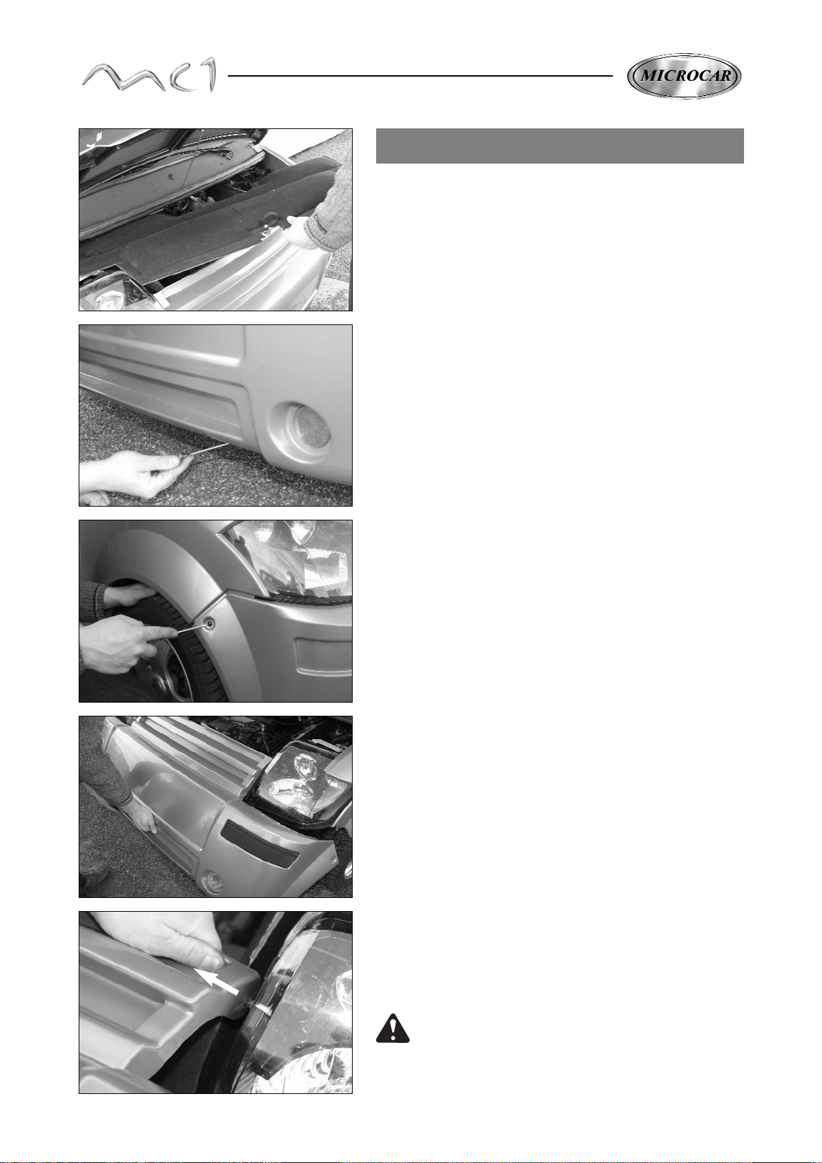
19
FRONT BUMPER REMOVAL
Open the bonnet and take out the superior soundproofing.
Thanks to a screwdriver, take out the 2 black plastic rivets
inferior fixing.
Take out the 2 black plastic rivets from the wings
Fall over the bumper to the front and make it turn around its
superior fixing pegs on the sealed beam units.
Take the bumper out of the superior fixing pegs.
Use the flexibility of the ABS bumper to make this operation.
Do not force or break the centring pegs of the
sealed beam units.
The fitting of the bumper is made at the reverse from
the removal operations.
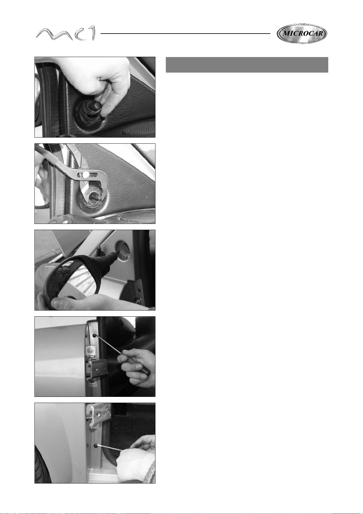
20
FRONT WINGS REMOVAL
Take out the door.
Take out the front bumper (voir page 19).
Take off the gaiter nut cover which fixes the door mirror.
With a combination pliers, take out the plastic nut from the
door mirror fixing.
Take out the door mirror.
With a screwdriver, take out the black plastic rivet of the superior
fixing from the pillar wing.
Take out the black plastic inferior fixing rivet.
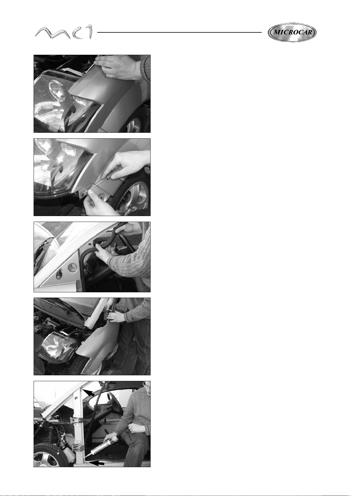
21
Take out the black plastic superior front fixing rivet.
Take out the black plastic inferior front fixing rivet.
Take out the door joint.
Take out the aerial of the left wing (1 fixing screw)
Remove the outside temperature sensor of the right wing
(Cyanocrylate glue)
Take out the wing.
The fitting of the wing is made at the reverse from the
removal operations.
When reassembly the wing, after having cleaned the residues of
silicone, put 2 waterproof lines of silicone (ref 0022509)
(see picture), up and down the pillar of the door to avoid the
water infiltration.
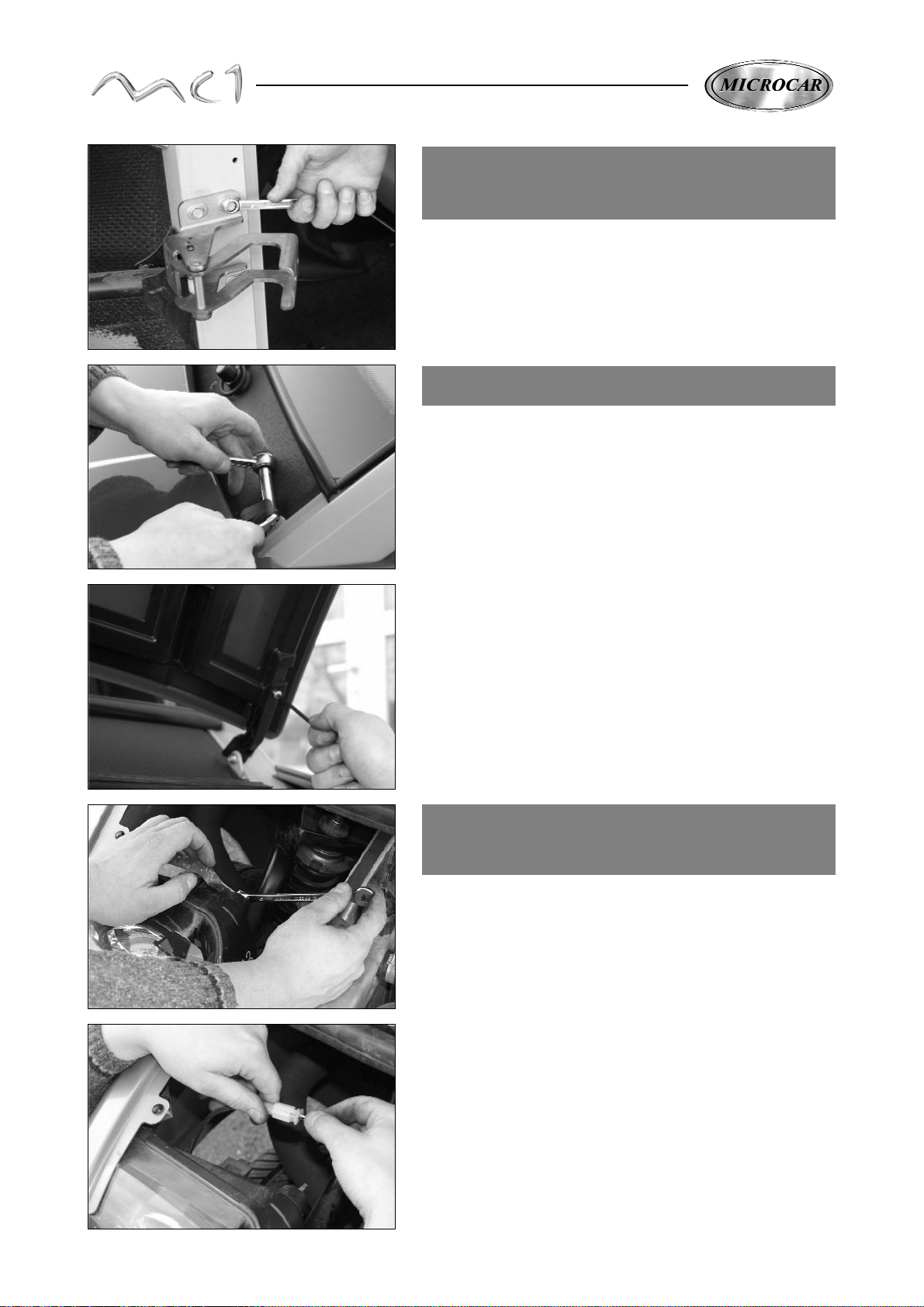
22
DOOR HINGES
REMOVAL
Take out the door (see page 8).
Take out the front bumper (see page 19).
Take out the front wing (see page 20).
Take out the door hinges, 3 fixing screws per hinge
(set screw when fitting again 7 N/m).
BONNET REMOVAL
Unlock the bonnet without opening and take out the
2 fixing bolts of the hinges from the front pillar.
(set screw when reassembling 3,5 N/m).
Take out the bonnet.
When reassembling the bonnet, adjust this one with the 2 regulating
screws to obtain a correct position with the body.
SEALED BEAM
REMOVAL
Open the bonnet.
Unplug the battery.
Remove the front bumper (see page 19)
Take out the superior fixing nut (see picture)
Unplug the 4 electric connections.
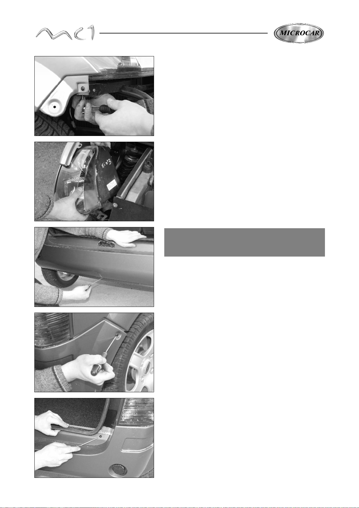
23
BACK BUMPER
REMOVAL
Take off the 3 inferior fixing nuts of the sealed beam
unit.
Take out the sealed beam unit.
The fitting is made at the reverse from the removal operations.
Open the rear window.
With a screwdriver, take out the black plastic inferior fixing
rivet of the back bumper.
Take out the 2 black plastic fixing rivets which fix the
bumper on the back wings.
Hold the bumpe rand take out the 2 last black plastic rivets
fix it on the the inferior cross beam.
Take out the bumper.
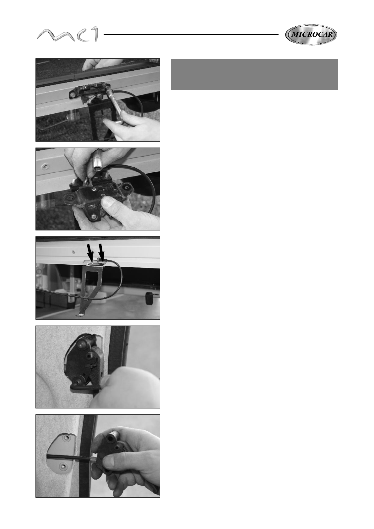
24
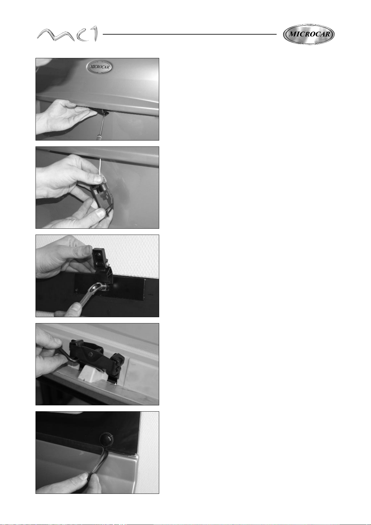
OPENING HATCHBACK
SWITCH REMOVAL
Bumper removal (see page 23).
Take out the 2 fixing screws of the hatchback lock with its 2
spacer rings.
(set screw when fitting 5 N/m).
Take the cable out of the lock.
WIth a drilling machine (drill Ø 5) take the 2 fixing rivets out of
bumper support, undo the duct from the switch cable
and take the support out.
Take out the 2 fixing screws of the hatchback opening
switch.
Take the switch out of its place.
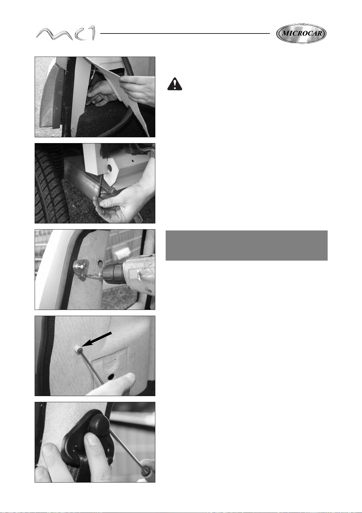
25
When assembling, to make the passage of
the cable easier, take locally the hatchback
joint out and rise up the interior trim to put
the cable in the back pillar hole.
Make the cable come out of the profile tube of the back pillar
and assemble at the reverse from the removal operations.
Take out the rear door (see page 14).
Take out the shelf which hides the luggage with a drilling
machine (drill Ø 5) take out the 2 fixing gaz strut support
rivets. Take out the rear plate.
INTERIOR TRIM REAR
QUARTER PANEL
With a screwdriver, take off the superior plastic inking cover of the belt.
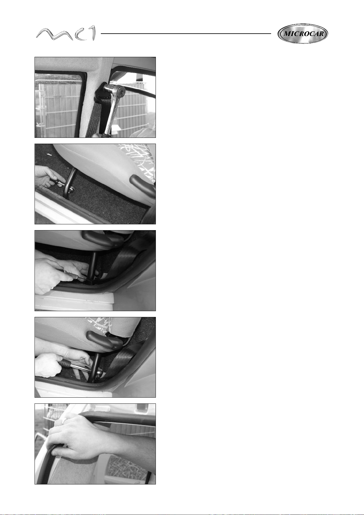
26
Take out the superior fixing screw, inking belt.
(set screw when reassembly 35 N/m).
Take the 2 fixing screws out of the bench seat support.
(set screw when reassembly 10 N/m).
With a screwdriver, take out the plastic cover of the inferior catch
of the belt.
Rise up lightly the bench seat and take out the screw of the inferior
catch of the belt.
(set screw when fitting back 35 N/m).
Take the joint out of the rear door.
27
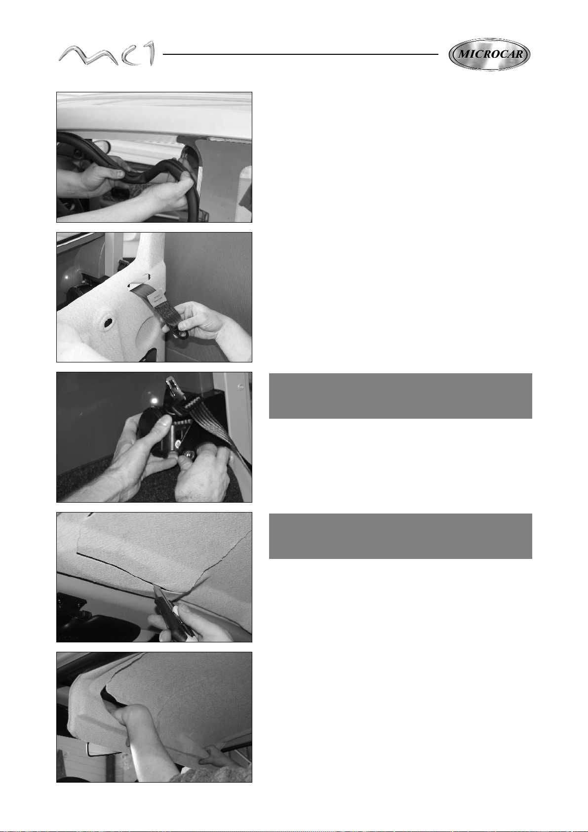
Take out partly the joint of the door.
Take out the trim and take out the belt and the beam.
The fitting is made at the reverse from the removal operations
SAFETY BELT RETRACTOR
REMOVAL
Take out the interior trim (see page 25).
Take out the fixing screw of the safety belt retractor
(set screw when fitting back 35 N/m).
CHANGING OF THE
INTERIOR ROOF TRIM
With a Stanley knife, make 2 cuts on the front part
of the roof trim.
Use the 2 cuts to take the roof in an easy way and to remove
the front trim.
Take totally out the roof trim taking it up to the front.
Remove a maximum of glue in the corners of the roof
to position easier the new trim.
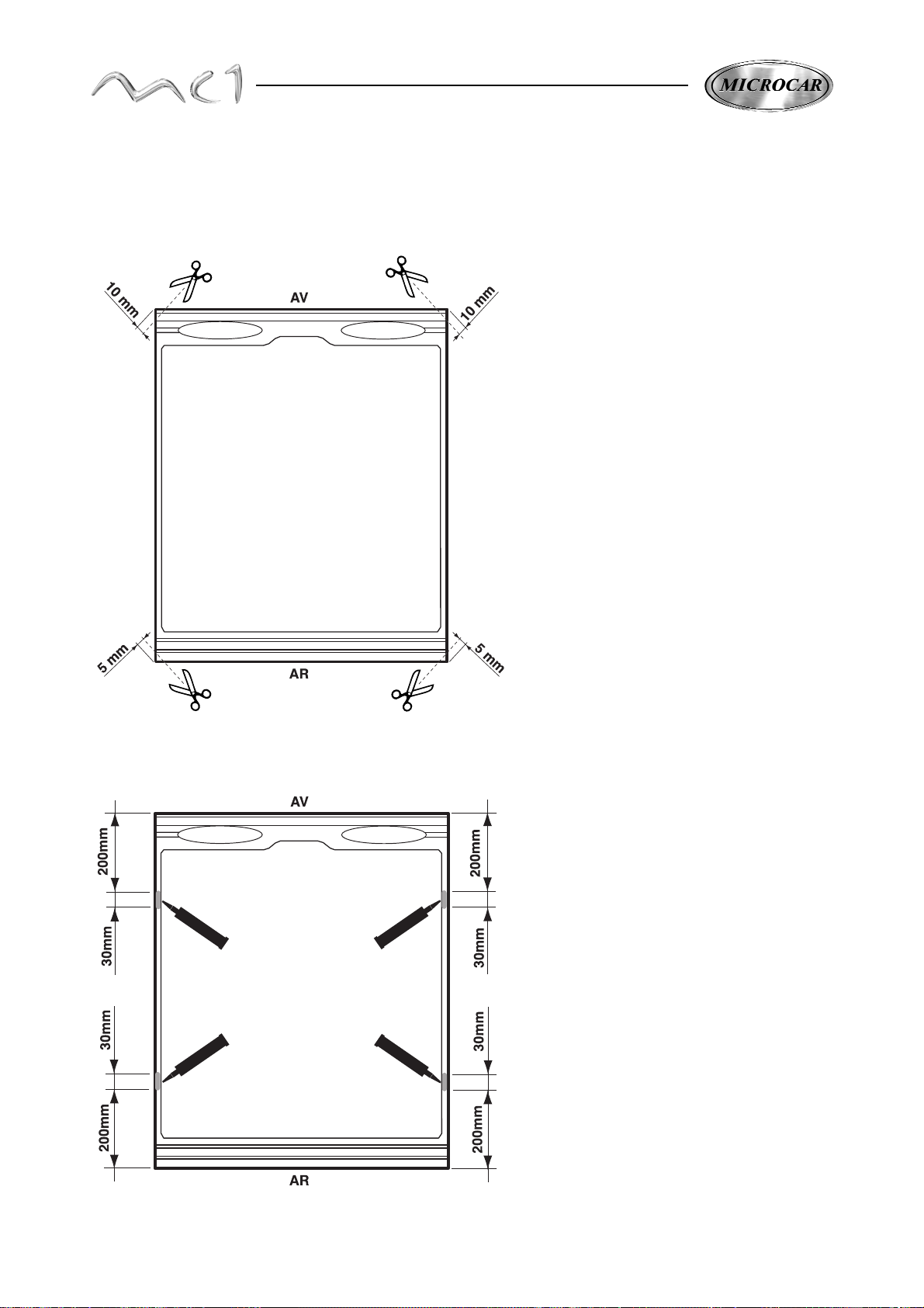
28
PREPARATION OF THE NEW ROOF TRIM
Cut the 4 corners of the roof trim at 45°.
10mm in front and 5mm in back following the
drawing.
Put 4 lines of glue (ref 0700200)
following the drawing.
Fit the trim and hold it with strips.
Stop the car a half day
(the necessary time to dry the glue)
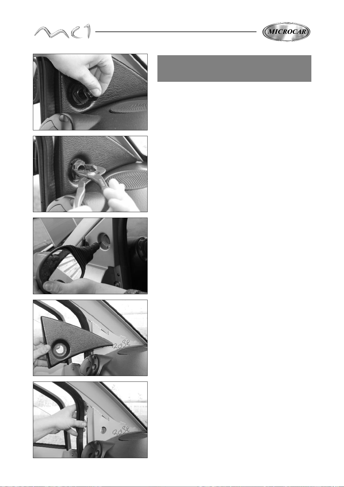
29
Open the bonnet.
Unplug the battery.
Take out the gaiter which hides the nut of the left door mirror.
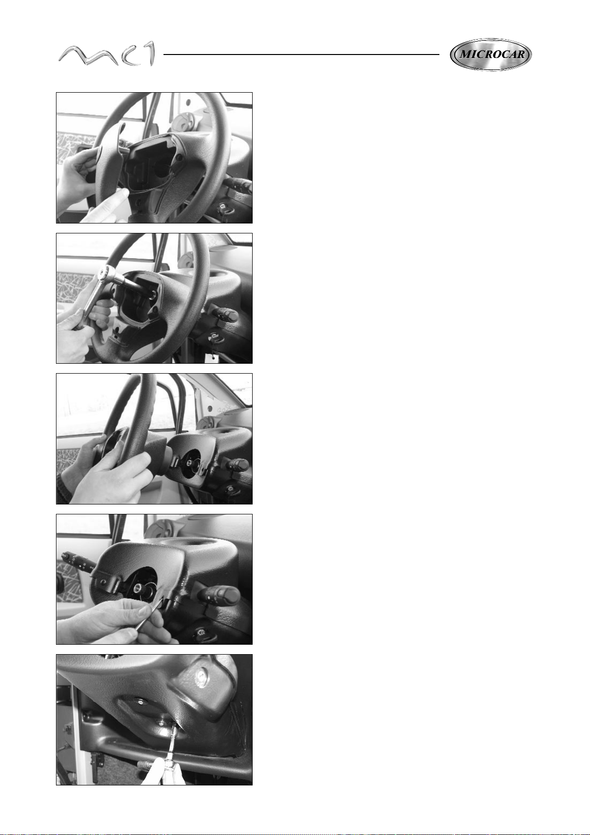
INSTRUMENT PANEL
REMOVAL
With a combination pliers, take out the fixing palstic
nut of the left door mirror.
Remove the left side door mirror.
Take out the left side interior cover.
Take out the 2 joints of the front part of the right and left doors.
30
Remove the central cover of the steering wheel.
Take out the central fixing screw of the steering wheel.
(set screw when fitting 30 N/m).
Take out the steering wheel of the steering column.
With a screwdriver, take out the 3 black fixing plastic rivets
of the column covers.
Take out the 2 fixing screws of the inferior column cover.

31
Take out the inferior column cover.
Take out the superior column cover.
Unplug the connectors of the electric beam from the
lever.
Take out the 3 cruciform fixing screws of the lever.
Take out the lever.

32
EVENTUAL STARTER SWITCH
REMOVAL
Position the ignition key between the mark M and A and
with 2 screwdrivers, retract the 2 holding lugs of the stater switch.
Take out the fixing screw of the starter switch.
Take out the starter of its sleeve.
Take out the radio.
Check the form of the radio and unplug it.
Unplug and take out the 2 electric controlled
windows.

33
Unplug the connectors on the distress signal switch
and the 2 connectors of the cigar lighter.
Take out the bulb of heating switch support.
Take out the button of the distress signal.
Take out the ventilation switch cover.
Take out the central fixing nut of the ventilation switch
Take out the reverser lever gaiter

34
Take out and unplug the 2 loud speakers of the instrument
panel.
With a screwdriver, take out the black plastic inferior fixing rivet
of the instrument panel.
Take out the 2 left and right black fixing plastic rivets of the
instrument panel.
Undo the heating throttle switch on the housing diffuser.
Undo the heating fan switch cable, engine compartment side.

35
Take out lightly the instrument panel and unplug the
instruments from the back.
Disconnect the 2 ducts of the fans.
Take out the instrument panel.
The reassembly is made at the reverse from the
removal operations.
REVERSER LEVER
REMOVAL
Take out the instrument panel (see page 29).
Take out the 3 fixing screws of the reverser lever
unit.
To take out only the lever, take the 2 side screws
and the screw down the lever and take out the Yoke axle
of the switch cable.

36
REAR QUARTER PANELWINDOW REMOVAL
2
1
Insert a piano rope between the door pillar and the rear quarter panel.
The piano rope is inside the window glue kit ref 0700200
Cut the glue joint on the side of the window and take it out.
Take care not to cut the inside trim.
For the assembly of the rear quarter panel window, clean all the
residues of the glue which stay on the body.
To glue the rear quarter panel window, use the kit glue (ref 0700200)
and the primary ABS (ref 1002818).
• Degrease (Adhekit ref. 1002659) or alcool.
• Apply the primary of the glue kit (ref 0700200) on the alu surfaces
(1) and on the side of the quarter light gluing surface.
• Apply the primary (réf. 1 002 818) on the ABS (2).
Some primaries make the ABS reacted
use only the primary (réf. 1 002 818).
To have a perfect window, you must primarise
the 2 parts to glue.
The primaries must be applied at least 5 minutes
before the gluing of the windows.
The primaries keep their efficiency during 72
hours.
Apply a line of the glue which is in the kit on the primary and
lift up the window, check its well centring on the body and hold
it in position with strips.
Stop the car during the 6 following hours.

37
BACK WHEEL TRIM REMOVAL
With damaged wood scissors and a thermal scrapper
unglue the wheel trim rear quarte panel from the back wing.
Unglue the wheel trim from the pillaracting from low to high.
With a Stanley knife, cut the upper joint next to the ABS of the wheel
trim.
Heat and unglue the covering of the roof.
BACK WING REMOVAL
Remove the hatchback (see page 14)
Remove the back bumpers (see page 23)
Remove the inside trim (see page 25)
Remove the back lights.
Remove the quarter light (see page 36)
Unglue and take off the rear side panel groove.
Do not warm up the ABS more than 60°
It is better to use an adjustable thermal scrapper.
Do not warm up the ABS of the roof more than 60°

38
Take out the striker plate.
With a screwdriver, take out the filler neck.
Disconnect the chute of the body.
With wood scissors and thermal scrapper, unglue the upper part
of the back wing.
Warm up the last points where the glue catches respecting the
maximum temperature not to damage the other ABS pieces
and take out the back wheel trim.
NOTA : When reassembly, the wheel trim must imperatively be
replaced by a new piece.
Do not warm up the ABS more than 60°

39
From the inside of the car, remove the wing from the floor.
Unglue the wing from the waterproof chute piece.
Remove the wing from the back door pillar starting from the top.
Take out the back wing.
Unglue the lower part.
Do not burn the carpet.

40
Remove the piece from the back carcase pillar.
Remove the low part on the back cross beam.
Take out the back waterproof pieces.
Use the glue kit TWINTEX -ABS-ALU ref 1002657
The fitting is done at the reverse from the removal operations.
With wood scissors, remove the back waterproof pieces.
NOTA: Those operations do not necessarily require
the use of a thermal scrapper.
BACK WATERPROOF PIECE REMOVAL
Degrease the parts which must be glued with the
product in the kit (ref 1002659)
Clean all pieces which must be fitted again.
Clean all the glue residues which stay on the pieces which must be
assembled.

41
Act step by step.
Glue and position each piece holding in position
with a clamp during 4 hours.
The fire must be made with a gun. Flame the side which must be glued.
(the smoother)
All the Sandwiform surfaces will have to be fired before
being glued.
All the ABS and Alu surfaces which must be glued
will have to be degreased with the cleanerdegreaser (ref 1002659)

42
Take out all the frame joints of the windscreen. Take out the inside
door mirror.
With a pliers, insert a piano rope delivered in the kit (ref 0700200)
between the pillar and the windscreen and cut the glue fixing
joint of the windscreen all around it.
On the lower part, take care no to cut the instrument
panel with the piano rope.
Take out the windscreen.
WINDSCREEN REMOVAL
FRONT WINDSCREEN PREPARING
Fit 2 new joints (ref 0664097) on the upper and lower
part of the windscreen and cut them in the right length.
NEW WINDCREEN FITTING
Fit 2 new joints (ref 0664097) on the upper and lower part of
the windscreen and cut them in the right length.
Put a point of cyanocrilate glue in the corners.

43
Fit the inside door mirror on its support.
Clean all the glue residues which stay on the body.
Apply the ABS primary (ref 1002818) on the upper part of the
apron cover.
Alll the alu surfaces which must be glued will have to be degreased with the
product in the kit (ref 1002659).
Use the glue kit (ref 0700200)
Apply the primary all around the windcreen level with the joints.
Apply a line of glue on the primary and fit back the windscreen.
Check its well centring on the body, hold it in pressure in its definitive
position and stop the car during the 6 following hours.

44
ROOF REMOVAL
Remove the hatchback (see page 14).
Remove the windscreen (see page 42).
Remove the 2 finishing joints of the roof.
With damaged wood scissors and regulated thermal
scrapper, warm up the back part of the hatchback
(maximum temperature 60°) and remove the roof from the
back cross beam.
Do the same to remove the roof from the sides of the body.
Always start the removal of the back roof to the front
on the both sides, then remove it from the front cross beam.
Remove the roof.
Clean all the residues of the glue which stay on the body
frame. Degrease all the alu surfaces which must be glued with
the product Adekit (ref 1002659).
Put a line of glue in the corners on the front part of the frame
(glue kit TWINTEX-ABS-ALU ref 1002657)
NEW ROOF FITTING
Put a line of glue in the corners on the back parts of the frame.

45
Apply the ABS primary (ref 1002818) all around the parts
of the roof which must be glued.
Put a line of glue (ref 0700200) all around the support surface
of the roof.
Put the roof.
Check its well position on the body, hold it in pressure
in its definitive and let it dry 6 hours.
Clean with a spatula to take off the glue left in the corners.
Put back the 2 finishing joints of the roof.

46
SIDE BODY REMOVAL
Place the car on an elevator or on a classic stand.
Support on the front under the engine cradle.
• Remove the door (see page 8).
• Remove the hatchback (see page 14).
• Remove the front bumper (see page 19).
• Remove the back bumper (see page 23).
• Remove the bonnet (see page 22).
• Remove the front wing (see page 20).
• Remove the door hinges (see page 22).
• Remove windscreen (see page 42).
• Remove the roof (see page 44).
• Remove the inside trim (see page 25).
• Remove the quarter light (see page 36).
• Remove the back wing (seepage 37).
• Remove the back light and its waterproof piece (see page 37).
• Remove the safety belt kit and the striker plate (see pages 27 et 38).
• Remove the instrument panel (see page 29).
• Remove the opening switch of the hatchback (see page 24).
Support on the back under the cross beam and the axle.

47
Take out the upper fixing screw of the back shock absorber
(set screw when assembling 40N/m)
With damaged wood scissors and an adjustable thermal scrapper
(maximum heating temperature 60°), unglue the floor from the side
frame).
Unglue very carefully the apron cover from the frame
Take care not to damage the dash panel cover
because this one is weaker than the floor.
Remove the 2 upper fixing screws of the engine cable.
(set screw when assembling 22N/m)
Remove the 2 low fixing screws of the engine craddle
(set screw when fitting again 22N/m)

48
Remove the 2 fixing screws of the instrument panel cross beam
(set screw when fitting again 7N/m)
Remove the 2 fixing screws of the low back cross beam
(set screw when reassembly 9,5N/m)
Remove the 4 fixing screws of the rear axle support
(set screw when fitting again 9,5N/m)
Hold the body of the side and remove the fixing screw of the upper
cross beam of the windscreen (set screw when reassembly 9,5N/m)
Remove the 3 fixing screws of the upper back cross beam
(set screw when fitting again 9,5N/m)

49
Remove the side of the body
The reassembly of the side of the body is made at the reverse from the removal operations.
When reassembling, check very carefully the geometric dimensions of the body.

50
FLOOR SOUNDPROOF KIT GLUING
The soundproof floor kit is fixed with glue (Neoprene, Sicaflex...)
Put some glue on the soundproof kit components
Position the components and plaster them down well on the floor
to spread the glue.

51
SOUNDPROOF APRON KIT GLUING
The soundproof apron kit is available under the reference 1002454.
The gluing of the soundproof apron kit is made with glue (Neoprene, Sicaflex...) as for the
soundproof kit floor.
Soundproof greneral view after gluing.

52
ABS REPAIRING
When the ABS is broken or deeply scratched, with a drilling
machine, make a hole at the 2 ends to stop the break.
Do a milling on a deep scratch
(see drawing)
Make a milling on the both sides on a break
(see drawing)
Always use an appropriate cut speed
to avoid making the ABS melted down.
faire fondre l’ABS.
Use the following products to repair the ABS
A - ABS degreasing (réf. 1 003 036)
B - Kalico fiber (réf. 1 003 037)
C - Waterproof sticky strip (réf. 1 003 038)
D - ABS repairing kit + 2 mixers (réf. 1 002 656)
E - Mixers 50 cc (réf. 0 700 249)
In case of scratch :
• Wet lightly a rag with the degreasing (A) and degrease the
surface which is to glue.
In case of break :
• Wet lightly a rag with the degreasing (A) and degrease the
surface which is to glue.
Break
Scratch
A
C
D
B
E
• Fill in again the break using te reparing ABS kit (D).
Drying time : 3 hours
Do not make the degreasing poured too much
on the ABS
Do not make the degreasing poured too much
on the ABS
• Apply a sticky strip (C)on the break, outside to avoid
excess glue.

53
Inside,fill in again the break using the ABS repairing kit (D)
apply the Kalico fiber (B) on the glue to reinforce the repairing.
Drying time : 3 hours
After drying :
Take off the sticky strip outside and sand the repairing
to obtain the original form of the part.
Apply a body finishing mastic, to fill in the scratches cased by
the sanding.
Make a finishing sanding.
ALU REPAIRING
Clean and degrease the aluminium parts to repair.
Apply a specific alu mastic for the repairing.

54
FLOOR REPAIRING
The floor material(Sandwiform) is made with a cellular
plate (A) (smocking) recovered with 2 Twintex sheets
(B) and 1 of it is recovered with a finishing carpet inside.
In case of shock or break, it is necessary to make the
repairing as said above.
Pre cut the Twintex sheet outside (without
carpet) ~ 4 cm around the damaged part.
Avoid cutting the smocking.
Take off and cut the damaged Twintex sheet.
Charge the smocking with the Sandwiform with the glue kit
réf. 1 002 657.
The rigidity of the part won't be ensured with
the repairing glue kit.
Cut a piece of Twintex sheet (ref 1002806)
Flame the side which is to glue (the smoother)
For any gluing on the sandwiform, it is necessary to
flame the parts which are to glue.
Without flaming, the gluing won't work on the twintex.
B
B
B

55
Put the black twintex part on the roof part which is to repair
and apply the repairing kit glue (ref 1002657)
Hold the parts in contact, plastered down.
Drying time : 6 hours.
Use the carpet kit repairing (réf. 1 003 030).
The carpet can be glued with a neoprene glue or with teh repairing kit
(réf. 1 002 657).
Be carefull to the gluing way.
The glued sid emust be the flamed side.
The flaming ensures the glues, mastic and paint
to stay. You can obtain it with a speed passe of a
flame on the surfaces without burning the material
(transformation of surface molecules)
CARPET REPAIRING
For a good waterproofness of the sandwiform
use the product 3M ref 08868 indicated in the
technical information 247.

56
PAIINTING FORMULA AND COMPOSITION : MC1 water formula
Blue
OXYGEN
M 162
2003
Red
SPORT
N 327
2003
Grey
Métropolitain
N 501
2003
Grey
Body
Frame
2003
SIKKENS
AKZO NOBEL
334WB 874,6
955 894,7
099 922,8
744 964,4
379 1056,3
ot os beeing
made
It is beeing
made
It is beeing
made
GLASURIT
M4 731,6
M010 876,7
M176 953,4
M011 994,8
A997 1011,4
A503 1023,8
A031 1035,8
A550 1044,1
M4 603,6
M99/03 610,6
A359 811,6
A323 928,1
A329 1008,5
A926 1018,5
M4 700,6
M99/07 739,4
M99/04 762,7
A926 853,7
A550 886,6
A031 907,9
A097 915,7
M1 1008,7
Step 1
M4 731,2
M99/03 819,6
M011 897,6
M506 923,6
A031 1006,8
A926 1034,1
A149 1054,9
Step 2
923-155 545,5
522-322 974,1
ICI AUTOCOLOR
Sous couche
P565-888 1626
Couche principale
P967-9957 309,3
P967-9933 523,8
P967-9938 573,8
P978-9951 618,5
P967-9954 784,8
P968-9988 1017,2
P275-366/372A 1035,1
P935-2018 1138,6
Sous couche
P565-889 1624
Couche principale
P967-9971 553,2
P967-9921 627,5
P967-9907 664,6
P968-9989 681,1
P978-9951 695,1
P968-9988 728,1
P967-9935 783,4
P967-9926 1022,8
P275-366/372 1031
P935-2018 1134,1
Sous couche
P565-888 1626
Couche principale
P967-9938 565,5
P967-9948 716,2
P967-9957 750,1
P967-9920 767,1
P978-9951 787,8
P968-9986 863,2
P968-9988 1017,8
P275-366/372 1036,7
P935-2018 1140,4
Sous couche
P565-888 324,9
P565-889 1624,4
Couche principale
P968-9987 765
P967-9948 833,8
P967-9905 847,2
P978-9951 1038,4
P275-366/372 1057,5
P935-2018 1163,2
DU PONT
Sous couche
1401W 504,5
1421W 565
1406W 592,3
1428W 615,8
1430W 621,5
1620WB 915,1
1630WB 1110,9
Teinte de fond
1511W 90
1470W 101,1
1420W 102,7
1405W 103,6
1640WB 921,7
1650WB 1012,6
1464W 80,2
1453W 147,9
1539W 183,8
1468W 215,5
1450W 239,4
1506W 260,8
1405W 266,8
1402W 270,6
1640WB 645,1
1650WB 1019,7
1535W 168,6
1405W 211,5
1463W 242,1
1418W 270,2
1401W 297,5
1421W 318,2
1505W 337,5
1640WB 676
1650WB 1015
It is beeing
made
STANDOX
Sous couche
WB372 223,6
WB370 790,6
WB369 891,3
WB357 1006,1
WB373 1105,8
Teinte de fond
WB399 935,2
WB329 996,9
WB336 1027,8
WB386 376,8
WB398 645,7
WB361 899,5
WB311 1006,4
WB372 1024,9
WB393 192,1
WB398 698,1
WB009 760,7
WB372 948,2
WB357 983,5
WB370 1025,6
WB376 1030,1
394 789,5
370 986,8
363 1016,3
374 1045,8
369 1049,7
367 1051,7
PPG
412 361,7
417 567
405 681,1
483 756,1
485 824,5
408 889,7
491 954,9
413 987,5
400 1013,6
446 447,4
439 682,9
437 879,1
487 957,6
464 996,8
406 1008,6
413 1013,3
491 312
408 554,1
483 773,7
481 857,3
443 927,2
413 968,4
451 998,4
487 1010,9
4002 1015,3
main coat
483 778,4
400 914,6
408 992,4
423 1023,5
440 1029,3
Mat varnish
800 546,8
759 984,2
SPIES HECKER
Under coat
WB801 564,8
WB803 787,5
WB837 901,9
WB820 1002,2
WB822 1101,5
Back tint
WB888 931,5
WB870 993
WB886 1023,7
WB815 270
WB882 648,4
WB858 755,7
WB843 1010,5
WB803 1029
WB815 504
WB813 695,4
WB803 882,2
WB800 944,5
WB801 986,5
WB837 1021,7
WB829 1026,1
WB818 789,5
WB801 986,8
WB827 1016,3
WB805 1045,8
WB820 1049,7
WB807 1051,7

57
PAIINTING FORMULA AND COMPOSITION : MC1 Solvant formula
Blue
OXYGEN
M 162
2003
Red
SPORT
N 327
2003
Grey
Métropolitain
N 501
2003
Grey
Body
Frame
2003
SIKKENS
AKZO NOBEL
AUTOBASE +
Q914F 714,9
Q065 942
Q110 958,6
Q160 972,6
Q652 983,4
Q726 987,3
Q436 527,3
Q811U 542,3
Q271 568,6
Q190 618,5
Q726 673,5
Q279 769,1
Q065 998,9
Q811R 352,8
Q673 363,9
Q110 393,2
Q195 435,8
Q160 515,7
Q065 742,9
Q190 987,8
Q811E 356,8
Q671 366,7
Q328 378,6
Q235 395,1
Q914F 566,7
Q110 783,4
Q065 1017,4
GLASURIT
352-91 172,5
M010 677,7
M179 872
A531 908,6
A929 934,9
M25 954,3
A555 960,8
352-91 174
M99/20 195,5
A353 575,1
A324 756,3
A335 876,8
A125 901,1
A929 911
352-91 174
M99/20 517,8
M99/19 552,5
A929 690,7
M1 808,4
A531 885
M25 925,9
A353 929,9
First step
352-91 174
M011 732,4
M99/20 776,8
M99/12 802,1
M506 816,8
M25 899,8
A929 933,8
A307 959,1
M105 960,8
Snd step
923-144 535,9
522-322 974,3
ICI AUTOCOLOR
P425-988 194
P420-933 334,3
P425-900 371,4
P425-948 379,6
P425-954 441,5
P425-957 581,8
P192-5600 969,7
Sous couche
P565-889 1624
Couche principale
P425-971 481,1
P425-921 553,3
P425-900 589,3
P425-984 619,3
P425-989 643,4
P420-907 679,4
P429-976 733,5
P420-926 950
P192-5600 1010,1
Sous couche
P565-888 1626
Couche principale
P425-986 351,7
P425-948 519,1
P425-900 591,9
P420-960RT 616,2
P425-988 635,6
P425-957 667,2
P420-920 740
P420-938 1025
Sous couche
P565-888 1626
Couche principale
P425-987 461,9
P425-948 496,5
P420-905 503,4
P425-900 757,5
P192-5600 1034,7
Vernis mat
P565-554 501,6
P100-2020 668,9
P190-XXXX 1003,2
DU PONT
Under coat
AM1 114,7
AM6 170,3
AM21 203,6
AM28 222,6
AM31 237,9
XB155 468,8
XB165 977,8
Back tint
AM732 97,4
AM70 135,4
AM2 173,2
AM5 176,3
AM20 177,3
XB155 401,4
XB165 949
AM64 207,3
AM63 317,7
AM50 357,1
AM66 394,7
AM2 422,1
AM77 449,5
AM94 459,2
AM5 464,4
XB155 957,6
AM94 107,6
AM21 207,1
AM5 292,7
AM14 367,5
4530S 422
AM1 451,3
AM31 476
AM64 482,3
AM46 485,1
XB155 982,6
AM1 117,5
AM95 175,7
AM17 220
AM5 245,4
AM70 247,4
XB155 462
XB165 989,7
STANDOX
Under coat
MB563 233
MB570 841,8
MB855 892,1
MB589 974,1
MB859 1018,1
Back tint
MB299 769,6
MB591 844,1
MB586 911,1
MB572 926,9
MB561 445,4
MB883 776,3
MB811 846,1
MB810 903,3
MB598 929,5
MB571 937,6
MB593 206,6
MB598 637,5
MB008 703,1
MB571 824,4
MB885 889,1
MB570 948,6
590 718,5
570 880,1
563 924,9
574 942,8
569 948,2
585 950
PPG
954 880,7
756 933,5
776 957
753 971,7
755 980,5
791 330,4
773 519,2
759 672,6
953 761,1
779 843,7
792 914,5
752 938,1
772 955,8
768 328,4
759 574,7
767 684,7
740 793,1
755 852,2
741 894,9
954 935,9
953 952,3
Main coat
768 725
753 886,1
759 939,8
740 969,3
778 981,7
779 984,4
Mat varnish
800 546,8
759 984,2
SPIES HECKER
Under coat
MB501 606,4
MB527 838,5
MB538 920,2
MB556 970,3
MB554 1014,1
Back tint
MB299 769,6
MB591 844,1
MB586 911,1
MB572 926,9
MB582 332,3
MB543 779,5
MB542 837
MB558 907
MB510 933,3
MB502 941,5
MB510 429,2
MB513 635
MB502 755,8
MB799 821,1
MB547 885,5
MB501 944,8
MB514 718,5
MB501 880,1
MB527 924,9
MB505 942,8
MB520 948,2
MB552 950

58
SOUNDPROOF ENGINE
PANEL REMOVAL
Remove the front bumper (see page 19).
Remove the 2 lower flaps of the bumper support
Take off the 2 lower fixing screws of the front soundproof
panel.
Take out the 2 upper fixing screws of the panel.
Take out the fixing screw on the right side.
Undo the soundproof panel taking it to the front.
Take out the 3 fixing screws of the right lower
soundproof panel.

59
Take out the 3 fixing screws of the lower left soundproof
panel.
Take out the 3 fixing screws of the lower lright soundproof panel.
Take out the waterproof radiator sheet metal and
take off the soundproof right panel taking it out to the front.
Take out the 3 fixing screws of the upper left soundproof
panel.
Take out the fixing screw of the left soundproof panel
and take out to the front the panel.
The fitting of the panels is made at the reverse from the
removal operations.

60
TRANSMISSION
REMOVAL
Place the car on an elevator or on a chassis stand.
Remove the front wheel.
(set screw when fitting again 120N/m)
Take out the suspension arm fixing screw.
(set screw when reassembling 40N/m)
With a hub puller (FACOM ref U16B), uncouple the suspension
arm from the hub.
Take out the transmission end screw on the hub
(set screw when reassembling 120N/m)
Uncouple the hub of the transmission
With a screwdriver, act as a lever to disconnect the
reverser drive axle and take off the transmission.

61
TRANSMISSION GAITER CHANGE
Remove the fixing gaiter collars.
Drag the gaiter on the shaft to free the joint.
Separate the fixing circlips from the transmission shaft.
Take out the gaiter.
After having greased the joint and fitted a new gaiter, fit all back
at the reverse from the removal operations.
The 2 transmission gaiters are not identical, respect the
fitting way (see drawing below)
Wheel Side
Reverser axle side

62
VARIATOR REMOVAL
The complete variator is adjusted in the factory and in case of repairing, it is necessary to use the MICROCAR
original pieces.
It doesn't require a lot of maintenance but to obtain a maximum performance, it is important that the mobile flanges
slide freely. So it can be necessary to clean it well.
POWER PULLEY REMOVAL
NOTA : The first MC1 models can be equiped with the same
variators as the VIRGO.
The adjustments are different, see specific paragraph
(page 64 et 65).
Take out the screw and its fixing washer and take out the pulley
(set screw when reassembling 60N/m)
Take out the nut and its washer bell lock.
(set screw when reassembling 100N/m)
Take out the bell.

63
Take out the 3 blocks with their flyweights and sounproof springs
Replace the springs in case of wear.
Be carefull to the fitting way of the blocks, they must run freely
in their place.
Take out the half pulley of its axle.
NOTA : For a cleaning, it is not necessary to dismantle the
inside spring of the mobile half pulley.
In case of change of the spring or the bearing :
- Compress the upper bearing and take out the inside circlips.
- Take out the upper bearing
- Find and take out the adjustment spacer of the spring.
Clean the parts with compressed air. Dry well and degrease
the pulleys (lubricate with fine oil the axle of the fixed half pulley)
The fitting operations of the power pulley are made at the
reverse from the removal operations.

64
• Position the belt setting washers (A)
(Réf. 0 782 373 et 0 782 374) on the shaft of the fixed half pulley.
• Position 4 adjustment spring spacers (B) thickness 1,2mm (Réf. 0 780 352) in the lower bearing (D)
• fit the spring (Réf. 1 000 660).
• Position 2 adjustment spacers (B) thickness 1,2mm (Réf. 0 780 352) in the upper bearing (E)
• Position 1 adjustment spacer (C) thickness 0,6mm (Réf. 0 780 357) in the upper bearing (E)
NOTA : Always share the number of adjustment spacers on each side of the spring.
POWER PULLEY SPRING SETTING
ADJUSTMENT IN THE FACTORY
1ST VERSION MODEL
D

65
• Position 5 adjustment spring spacers (B) thickness 1,2mm (Réf. 0 780 352) in the lower bearing (D)
• fit the spring (Réf. 1 000 660).
• Position 5 other adjustment spacers (B) thickness 1,2mm (Réf. 0 780 352) in the upper bearing (E)
• Position the adjustment spacer (B) thickness 0.6 mm (Réf. 0 780 352) in the upper bearing (E)
• Position the belt setting washers (A) thickness 1mm (Réf. 1 002 568) inside the spring
NOTA : Always share the number of adjustment spacers on each side of the spring.
POWER PULLEY SPRING SETTING
(ADJUSTMENT IN THE FACTORY)
2nd VERSION MODEL

66
RECEIVER PULLEY
DISMANTLING
Take off the fixing nut of the receiver pulley
(set screw when fitting back 60N/m)
Take out the receiver pulley of the axle box and take out the key.
Find the spring position.
Take off the inside circlips compressing the fixed came.
Take out the fixed came and the spring.
Take out the half mobile pulley.
Clean the pieces with diesel and compressed air
Dry well and degrease the pulleys (lubricate with fine oil the
axle of the half fixed pulley).

1ST VERSION RECEIVER PULLEY FITTING
For the fitting, put the mobile half pulley
on its axle, position the spring on the mobile
pulley in the hole (C) and position the
other spring end in the hole (2) of the fixed
came.
C
2
67
2ND VERSION RECEIVER PULLEY FITTING
For the fitting, put the mobile half pulley
on its axle, position the spring on the mobile
pulley in the hole (A) and position the
other spring end in the hole (4
) of the fixed
came.
A
4
Position the key of the shaft on the same line as the came.
Compress the spring and turn the mobile half pulley
at the reverse from a watch needles , to change a came step.
Fit back the outside circlips.
NOTA : For the usual maintenance of the receiver pulley,
it is not necessary to take it out, a diesel cleaning on the sliding
(behind the spring) is sufficient.

68
CHANGER BRIDGE REMOVAL
Unplug the battery using the red speed (+) disconnecting cable
cable terminal.
Take off the lower soundproof panel.
(see page 58).
Take off the fixing screws of the suspension arms of the
hub.
(set screw when fitting back 40N/m).
With a hub puller (FACOM ref U16B) uncouple the suspension
arms from the hub.
With a screwdriver, act as a lever to disconnect the changer
bridge and take off the transmission.

69
Before untightening all the fixing of the changer bridge
wedge the underneath of the engine sump to prevent
it from tipping.
Take out the 2 fixing bolts of the changer bridge on the back rubber
mounting.
(set screw when fitting back 12N/m)
• Untighten the 2 fixing screws of the changer bridge support
(set screw when fitting back 30N/m).
•Hold the changer bridge and take out the 2 fixing screws (A)
(see drawing)
• Take out the changer bridge from below the car.
• Make the fitting at the reverse from the removal operations.
Take out the receiver pulley of the variator (see page 66).
Uncouple the changer bridge switch command
Unplug the speed sensor.
A

70
1
6
2
4
5
3
8
9
10
11
4
14
7
13
12
15
16
17
18
19
20
17
21
28
10
11
32
31
30
29
27
26
25
22
23
24
41
40
39
38
37
36
35
34
33
22
23
24
25
26
27
28
29
30
31
32
33
34
35
36
37
38
39
40
41
Left housing bridge
Right housing bridge
Housing bridge joint
10 x 10 x 0,9 socket
Ball bearing
Waterproof ring
Entry shaft
2nd reduction shaft bearing
Spring ring
Waterproof ring
Ball bearing
Reverse gear shaft
Mobile reverse gearing
2nd reduction shaft
Spring ring
1st reduction shaft
Ball bearing
Fixed reverse gearing
Coupling sleeve
Spacer
Breather cap
1
2
3
4
5
6
7
8
9
10
11
12
13
14
15
16
17
18
19
20
21
Transmitter joint
Digital meter transmeter
M4 x 12 screw
12 x 1,5 level screw
12 x 18 x 1,5 washer
Drain plug
Ball
Spring
screw
TH 10 x 1,5 screw
Lever spring
washer support
Differential
Gear lever group
O ring seal
Spring ring
Selector guide
Selector lever
Selector washer
Selector nut

71
REVERSER TRANSAXLE
REMOVAL
Before opening the door , we advice you to clean it with petroleum or
diesel and to dry it with compressed air.
Drain the gearbox oil by its oil change hole (27)
Take out the holding screw (31), the spring (29) and the ball (28).
Take out the 8 screws that gather the 2 half housing
Separate the 2 half housing (1) and (2) lightly hiting
with a rubber hammer in the axle of the entry shaft (7).
Never introduce a screwdriver between the 2 half haousing
as lever , not to damage the joints.
Throw the old paper joint (3) between the 2 half housing
and take a new one for the fitting.
Take out the return spring.
Take out reverse gear axle (12).
Take out the entry shaft(7).

72
1
6
2
4
5
3
8
9
10
11
4
14
7
13
12
15
16
17
18
19
20
17
21
28
10
11
32
31
30
29
27
26
25
22
23
24
41
40
39
38
37
36
35
34
33
22
23
24
25
26
27
28
29
30
31
32
33
34
35
36
37
38
39
40
41
Left housing bridge
Right housing bridge
Housing bridge joint
10 x 10 x 0,9 socket
Ball bearing
Waterproof ring
Entry shaft
2nd reduction shaft bearing
Spring ring
Waterproof ring
Ball bearing
Reverse gear shaft
Mobile reverse gearing
2nd reduction shaft
Spring ring
1st reduction shaft
Ball bearing
Fixed reverse gearing
Coupling sleeve
Spacer
Breather cap
1
2
3
4
5
6
7
8
9
10
11
12
13
14
15
16
17
18
19
20
21
Transmitter joint
Digital meter transmeter
M4 x 12 screw
12 x 1,5 level screw
12 x 18 x 1,5 washer
Drain plug
Ball
Spring
screw
Vis TH 10 x 1,5
Lever spring
washer support
Differential
Gear lever group
O ring seal
Spring ring
Selector guide
Selector lever
Selector washer
Selector nut

73
Take out the intermediate gearing and the differential
(34).
Take out the different bearings with a universal hub puller
We advice you not to do anything on the differential (34)
In case of anomaly, replace the differential.
You must change the waterproof joint (3)
of the half housing when fitting back.
Maxi oil capacity : 0,5 liter.
Checking by the level screw (25).
For the fitting, follow the reverse operations of removal
Be carefull to the well position of the selector peg in the dog clutch sleeve.

74
STARTER REMOVAL
Unplug the battery using the disconnecting speed red cable
terminal (+).
Take out the air filter.
Take out the electric feed of the starter
Take out the variator (see page 62).
Take out the flywheel.
Take out the fixing starter support : 3 fixing screws on the engine
and 2 fixing screwson the bridge.
Do not completely take off the fixing axles
of the changer bridge box.
Take out the support and the starter.

75
ENGINE REMOVAL
Unplug the battery using the speed red (+)disconnecting cable
terminal.
Take out the front bumper (see page 19).
Take out the soundproof engine panel
(see page 58).
Take out the front cross beam (2 fixing screws) and the engine
hold cable.
Take out the power pulley and the belt (see page 62).
Take out the throttle cable.
Find and take out the 2 fuel feed hoses
Fix the engine with a hoist or a workshop crane.
Uncouple the engine from the changer bridge.
(2 fixing screws).
Take out the fixing screws of the engine on the front
front rubber mounting.
Take out the engine of its place.
Drain the cooling system at the level of the
radiator inside hose.
Take out the 2 heating tubes
Take out the 3 cooling hoses
Unplug all the electric feeds
Uncouple the tube from the exhaust
manifold.
Take out the fixing screw of the exhaust
tube on the engine housing.

76
ENGINE CRADLE REMOVAL
Unplug the battery using the red speed disconnecting (+)
cable terminal.
• Remove the front bumper (see page 19).
• Remove the soundproof engine (see page 58).
• Remove the 2 doors (see page 8)
• Remove the 2 front wings (see page 20).
• Remove the 2 light optics (see page 22).
• Unplug the 2 heating hoses.
• Find and take out the 2 fuel feed hoses.
• Unplug the accelerator cables.
• Unplug the the changer bridge.
• Uncouple the tube of the exhaust manifold
• Take off the air induction duct
• Take off the exhaust fixing tube on the engine housing.
• Unplug the opening bonnet cable
• Uncouple the rack of the steering column (see page 96).
• Unplug the rigid tubes at the joint of front brakes fuses.
• Take out the windscreen washer tube.
• Unplug all the electric feed cables betwen the body and the engine cradle.
• Place the car on an elevator ar on a chassis stand.
• Take out the front wheels.
• Put a trolley under the engine cradle and chock the cradle.

77
Take out the fixing screws of the cradle on the engine, right side
(set screw when fitting back 22N/m)
Take out the fixing screws of the cradle on the engine, left side
(set screw when fitting back 22N/m)
With the trolley, take out the cradle of the body.

78
ENGINE CRADLE
EQUIPMENT
Fit the waterproof joint between the manifold and the exhaust tube
Be carefull to the fitting way, (boss up)
Fix the tubulure on the exhaust manifold with 2 M8 screws
without blocking them.
Fix the M12 lower fixing screw of the exhaust tube
on the engine, without blocking it.
Tighten the 2 M8 fixing nuts of the exhaust tube on
the manifold.
Tighten the M12 lower fixing screw of the exhaust tube
on the engine (set screw 45N/m).

79
Fit the interference eliminator wire on the engine housing.
Fit the holding belt clamp on the changer bridge with its washer
and its fixing screw.
Block the fixing screw of the holding belt clamp
(set screw 8N/m)
Put a circlip on the 2 exit changer bridge axles.
Settle, without driving them in, the 2 fixing screws of the changer
bridge with their washers.

80
Fit the changer bridge on their support and introduce the 2 fixing
screws.
Tighten the fixing screws of the changer bridge.
(set screws 60N/m)
Grease the 2 axles of the exit transmission and the
entry shaft of the changer bridge.
On the front of the engine cradle, fit a spacer washer
on the 4 fixing inserts of the elastic plots.
Fit the 2 elastic plots and fix them on the cradle with 4 screws
and washers (set screws 12N/m).

81
At the back of the engine cradle, fix 4 spacer
washers on the fixing axles of the elastic plots.
Fit the inside screws of the elastic plots and fix them on the
cradle with 4 screws and washers.
(set screw 12N/m)
Fit the fixed battery clamp.
Fix the electric fuel pump on the engine cradle with 2 rubber
washers, 2 bolts and 2 washers.
(set screw 12N/m)
Fix the steering rack on the cradle, 2 fixing screws + 2
washers (set screw 120N/m)

82
Fit the 2 suspension triangles on the engine cradle
(set not 70N/m)
With a hoist or a workshop crane, fit the engine on the
cradle.
Fit the anti-couple stop support clamp
Fit the conical stop on the anti-couple stop support
clamp.
Fix the changer bridge on the back elastic plots with a
washer nut. (set screw 30N/m)

83
Fix the engine on the front elastic plots with screws and
washers. (set screw 30 N/m).
Fit the receiver pulley on the changer bridge axle with its
key.
Fix the pulley with a washer and a nut.
(set screw 60N/m)
Fit the power pulley with the belt on the axle of the flywheel.
Fit its fixing screw with glue.
(set screw 60N/m)

84
Fit the exhaust tube rubber mounting.
Position the radiator on the engine cradle and fix it to the front
lwith a screw and a fixing washer.
Fix the radiator to the back with 2 screws and fixing washers.
Fix the upper hose between the radiator and the engine
with 2 serflex collars.
Fit the lower hose between the radiator and the engine with 2
serflex collars.

85
Fit the shock absorbers in the 2 hubs, fix them with a nut and washers
(set screw 25N/m)
Fit together the 2 transmissions on the axles of the
changer bridge.
Fit the lengther on the variator side.
Fit the hose Ø 10 with 2 collar clips.
Fit the banjo of the brake hose with a copper joint
on each side and fit it with its screw on the brake caliper.
Fit the lower ball joint on the hub and fix it with 3 screws and
3 washers (screw fitted on the brake)
(set screw 10N/m).

86
Fit the hub and the right shock absorbers on the
transmission (steering lever to the back).
Fix it on the suspension triangle with a screw
(set screw 40N/m)
Put the mudflap on the shock absorbers.
Fit the washers (1) and(2) on the shock absorber heads.
Fit the rubber mountings.
Position the shock absorber heads on the engine cradle
supports(4).
Fit the rubber mountings.
Fit the washers (6) and the nuts (7).
Block the fixing shock absorbers cap nut
(set screw 20N/m)
Fit the hub and the left shock absorbers on the
transmission (steering lever to the back).
Fix it on the suspension triangle with a screw
(set screw 40N/m)
6
7
5
3
4
2
1

87
Fix the 2 mudflaps on the engine craddle withe 4 black
plastic rivets.
Fix the 2 steering ball joints on the levers.
(set screw 22N/m)
Fit the screws + the hub axle wahers
(set screw 120N/m)
Fix the 2 brake fuses on the engine craddle
Fit the steering transmission on the rack, a fixing bolt +
washers
(set screw 22N/m)

88
BRAKE PADS
CHANGING
Always replace the brake pad complet train.
Lift up the car and take off the wheels
(set screw 60N/m)
On the front, unplug the wear light wire.
Take out if necessary, a bit of braking liquid of the tank thanks to
a syringue.
Put the 2 fixing axles to the outside.
Take off the fixing axles with holding pad springs.
With a combination pliers, compress the piston caliper
and push it in its place.

89
Take off the 2 brake pads
• Control the waterproofness of the piston and the good condition of the brake caliper
and the weak of the discs (the thickness of the discs must be between 4 to 5mm on the front
and 3 to 4mm at the back). Below these sizes, the discs must be replaced immediately.
• Set some new pads
• Fit back at the reverse from the removal operations
• Press several times on the brake pedal
• Control and complete the level of the necessary brake liquid, do the bleed of the brake.

90
FRONT HUB
BEARING CHANGING
Lift up the car on an elevator
Take off the wheel
Take off the brake pads (see page 88)
With a 6 sides key, take off the 2 fixing screws of the brake caliper
Take off the fixing nut of the steering joint.
(set screw when fitting back 22N/m)
Take out the steering joint, use a hub puller
FACOM Réf. U16B.
Take out the fixing nut hub of the lower pivot
(set screw when fitting back 40N/m)
With a hub puller FACOM Réf. U16B, uncouple
the hub from the suspension triangle.

91
Take out the fixing nut of the transmission on the hub.
(set screw when fitting back 120N/m)
Take out the transmission of hub
Take out the fixing screw of the shock absorbers on the hub
(set screw when fitting back 25N/m)
Take out the half train.
Take out the 4 screws of the wheels support
set screw when fitting back 60N/m)
Take out the wheel support end the brake disc.

92
FRONT BRAKE
H UB

93
With a circlips pliers, take off the circlips which hold the
bearing.
With a press, take out the bearing from its place
Replace the bearing and make the fitting at the reverse from
the removal operations.

94
BACK HUB
BEARING CHANGE
Put the car on an elevator
Take off the back wheel
(set screw 60N/m)
Take out the brake pads (see page 88)
WIth a 6 sides key, take out the 2 fixing screw of the
back caliper.
Take out the caliper of the disc.
Take out the central fixing of the hub
Set screw when fitting back 120N/m)
With a hub puller, take out the back hub
Replace the bearings
The fitting back is made at the reverse from the removal
operations.

95
BCKHU

96
STEERING
Place the car on an elevator
Take out the 2 front wheels
(set screw when fitting back 60N/m)
STEERING RACK
REMOVAL
Take out the 2 front wheels
(set screw when fitting back 22N/m)
Take out the 2 hub with a hub puller FACOM
réf. U16B.
Take out the fixing bolt and uncouple the steering column
of the rack
(set screw whenfitting back 22N/m)
Take out the 2 fixing screws of the rack.
(set screw when fitting back 120N/m)

97
Take out the rack
The fitting back is made at the reverse from the removal
operations
GAITER CHANGE
ON THE RACK
REPAIR RACK KIT
After having taken down the hubs.
Cut the fixing plastic collar gaiters and make the gaiters
slided to the exterior.
Fit back the new gaiters taking care to grease the rack
Use a standard grease.
Hardness regulating of the steering control. A regulating screw on
the rack allows the hardness of the steering to incresa or to
decrease.
For each regulating of the hardness of the rack
you must punch the nut to avoid it to
get out of control.
A repair steering rack kit which contains a bush + bearing +
joints is available under the reference :
1 002 788
Take out the waterproof bush.
Take out the inside circlip to take out the rack axle
Connecting rod
After having taken out the gaiter, with a screwdriver, take out the fins
of the brake washer of the notches of the ball joints.
With a vice pliers, untighten the connecting rod and take out
the connecting .
Crimp again the lock washer after the fitting of
the new connecting rod.

98
Make the alignment controlwith a specific machine. The regulating is made at the level of the steering hubs
The repartition of the steering must be equal on the right and on the left and the steering wheels in straight
position.
If you do not have any specific machine for the regulating of the adjustment, fix some rules on the back
wheels and regulate as before at the level of steering hubs.
The back train is regulated when building, so it is not possible to make any regulating.
ALIGNMENT
FRONT AND BACK GEOMETRIC TRAIN
SIZES CONDITIONS : discharged car filled up.
FRONT TRAIN
BACK TRAIN
ADJUSTMENT
L
0° ± 5’
R
0° ± 5’
BODY
L
0° ± 30’
R
0° ± 30’
PIVOT
L
16° ± 1°
R
16° ± 1°
CATER
L
4° ± 1°
R
4° ± 1°
ALIGNMENT
L
+ 25’ ± 25’
R
+ 25° ± 25’
BODY
L
- 25’ ± 25’
R
- 25’ ± 25’

99
Fill in the tank with braking liquid
Nota : make the bleeding after : every repairing
during which one the braking circuit has been
opened, and when it is necessary to push several
times on the pedal to obtain the braking or if
you feel an elasticity in the pedal.
BRAKING WITH A SPECIAL
MACHINE
• Follow the form of the constructor of the
used machine
• Start the bleeding by the wheel the faster of
the master cylinder and do as follow : back
right wheel, back left wheel, front right wheel
front left wheel
•Do not use again the drained brake liquid.
• Seal the air braking screws with the dust
covers after having made the braking.
• Press several times on the braking pedal
• Fill the liquid in the tank, at the end of the
circuit bleeding
• Make a try.
BRAKING HYDRAULIC CIRCUIT BLEEDING
BLEEDING WITHOUT SPECIAL MACHINE
Nota - During the bleeding operations, check if the level of the
liquid in the tank stays at the minimum.
•Control and if need be complete the level of the liquid
in the compensation tank. The bleeding must be made as
follow : back right wheel, back left wheel, front right wheel
front left wheel
• Take off the dust cover of the bleeding screw, connect the
tuyau de purge en laissant plbleeding tube letting plunge
the other end in a transparent container.
• With a apropriated key, open the bleeding screw with a half turn
and press on the brake pedal several times and in its total run
till the liquid which goes out don't have any air bubble
anymore
• Close the bleeding screw when the brake pedal is pressed
2 persons are necessary to make the bleeding in these
conditions. It is also necessary to always complete the level
of brake liquid which has gone out.
• Do the same on the other wheels in the indicated way
• Put back all the caps on every bleeding screw.
• Control the new level of the brake liquid in the tank and fill in
if need be.
• Press several times on the brake pedal.

100
• After having settled the 2 cables in the compensator
and be sured that the main circuit is correctly drained
• Press several times on the pedal.
• Control the untightened parking brake, the rotation
of the back wheels.
First adjustment:
Make a lever on the compensator and adjust the tension of
the cables with the regulating nuts of the compensator.
It is necessary to have 4 notches at the maximum
on the handbrake lever.
Ragulating :
The regulating of the handbrake must be checked
for each maintenance. The regulating must be only made
on the calipers.
1) Untighten the 2nd nut of the screw which provides
the lost.
2) Tighten the screw to put the pads in contact with the disc
(without forcing, tightening by hand)
PARKING BRAKE ADJUSTMENT
3) Tighten again the screw between 1/3 and 1/2
turn at the maximum (120 to 180°). The pads
must lap the disc without blocking the wheel in
in rotation.
4) Tighten again the 2nd screw on the washer with
a couple of 10 N/m without making the screw turned
5)The same for the 2nd calliper.
6) Check the deflection of the handbrake level
(4steps at the maximum).
• Grease the compensator.
• Be sure that the 2 cables slide correctly-
and the light of parking brake works
 Loading...