


1
Whats Miner M10 Operation
Guide
V1.1
(Simplified Version)
Shenzhen MicroBT Electronics
Technology Co.,Ltd

2
1. M10 Product Introduction
2.Whats Miner Connection and Racking Safety Notes
2.1.Miner Connection Notes
2.1.1.Power Supply Control Wire Connection Notes
2.1.2.Adapter Board Control Wire Connection Notes
2.1.3.Fan Connection Notes
2.1.4.Hash Board and Adapter Board Connection Notes
2.1.5.Power Supply Copper Busbar Connection Notes
2.1.6.Product Connection Check
2.2.Miner Handling and Racking Notes
3. Miner Configuration Environment Preparation
3.1.Miner Configuration Equipment List
3.2.Miner Network Environment
4.Miner Connection and Pre-Power Check
5.Miner Data Configuration(Configuration on the web page)
5.1.Query the dynamic IP address obtained by the miner
5.1.1.Run WhatsMinerTools software
5.1.2.Check the IP address Reported by the Miner
5.2.Configuration Pool&Worker Data and NTP Server Address
5.2.1.Configuration Pool&Worker
............................................................................................................
.....................................................................
.....................................................................................................
........................................................
......................................................
..............................................................................................
.................................................
.....................................................
.....................................................................................
...................................................................................
..........................................................................
.................................................................................
............................................................................................
.....................................................................................
..................................................
.....................................................
............................................................................
........................................................
.............................................
..................................................................................
5.2.2.Modify the NTP Synchronization Server Address (optional)
5.3.Configuration the Static IP Address (optional)
5.4. Chinese and English Language Switching of Miner Page
6.Miner Operation Status Check
.....................................................................................................
.................................................................
.................
7.Miner Batch Data Configuration, Miner Status Check, Firmware Upgrade
8.Miner Disassembly and Installation
8.1. Control Panel Disassembly and Installation
8.1.1.Control Panel Disassembly
8.1.2.Control Panel Installation
8.2.Power Supply Disassembly and Installation
8.2.1.Power Supply Disassembly
8.2.2.Power Supply Installation
8.3.Hash Board Disassembly and Installation
8.3.1.Hash Board Disassembly
8.3.2.Hash Board Installation
.............................................................................................
.....................................................................
.....................................................................................
.......................................................................................
.....................................................................
.....................................................................................
......................................................................................
.........................................................................
........................................................................................
..........................................................................................
.................................
错误!未定义书签。
................................
3
3
3
4
4
6
7
9
10
10
11
11
11
12
13
13
13
14
16
16
18
19
22
24
24
24
24
26
28
28
29
31
31
33

3
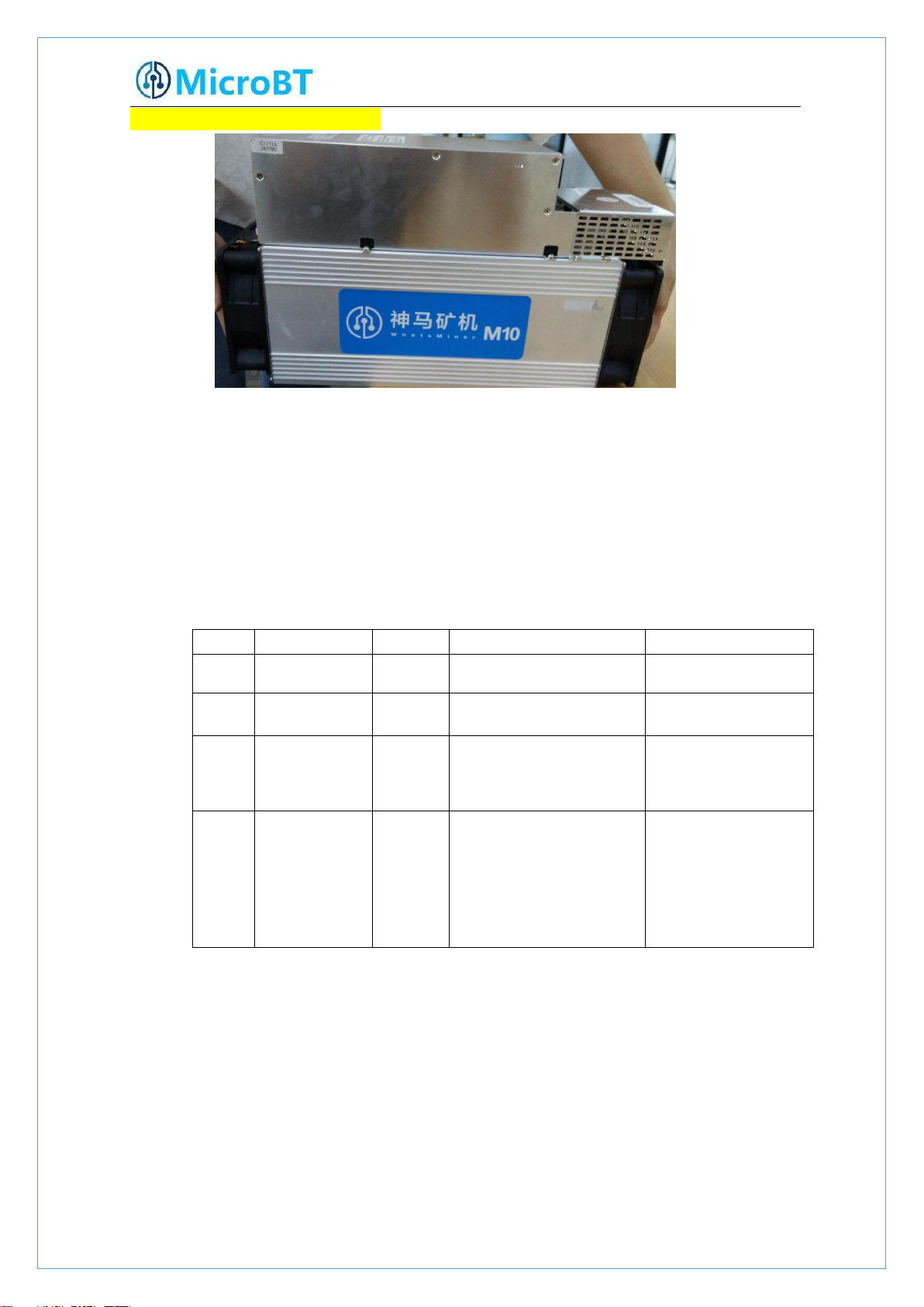
1. M10 Product Introduction
Whats Miner M10
Bitcion Mining Magic
Product ParameterIntroduction as below:
HashRate:33TH/s ±5%
Chip:315pcs 16nm ASIC
Power:2145W±10%
Power Rate:65W/T ±10%
Power Supply:Whats Miner Power Supply P10(220v,2145W ±10%)
Control Panel:Own
Environment Temperature:-5℃~40℃
Product Size:390mm*130mm*220mm
2.Whats Miner Connection and Racking Safety Notes
2.1.Miner Connection Notes
Check over the miner’s power supply control wire and adapter board control wire
and fan control wire to make sure connections are correct,the damage of control
board、hash board、transfer board、fan, etc. caused by incorrect connection will

4
not be covered by the warranty.
When connecting the wiring of the control board, the clasp must be corresponding,
and the pin cannot be inserted into the socket by force.If the backplug, the power may
burn the control board, burning the signal wire!
2.1.1.Power Supply Control Wire Connection Notes
The power control wire is 14pin, and the card slot is inserted relative:
Correct Connection: Incorrect Connection:
2.1.2.Adapter Board Control Wire Connection Notes
The adapter board control wire is 22pin, and the card slot is inserted relative:
Correct Connection:

5
Incorrect Connection:

6
2.1.3.Fan Connection Notes
The fan wire is 6pin, and the card slot is inserted relative:
Correct Connection:

7
Incorrect Connection:
2.1.4.Hash Board and Adapter Board Connection Notes
The socket of the adapter board and the pin of the hash board must be installed in
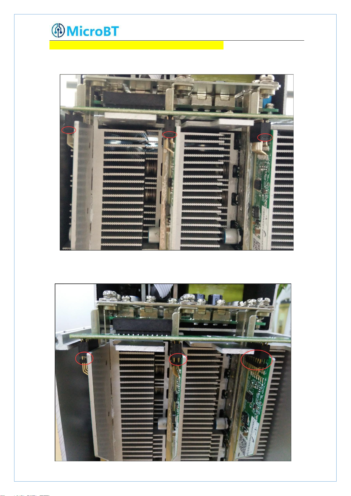
8
place to avoid other problems caused by contact problems!
Correct Connection:
Incorrect Connection:

9
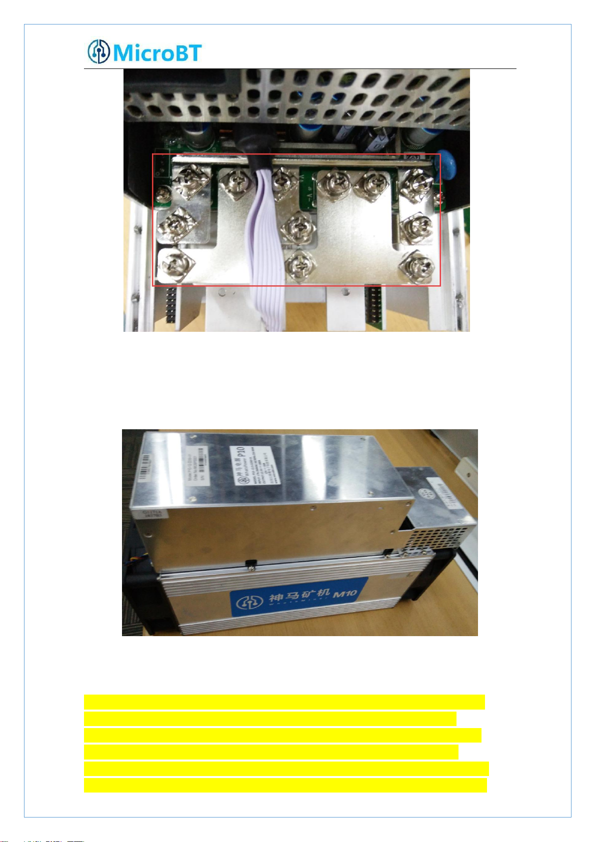
2.1.5.Power Supply Copper Busbar Connection Notes
When the power supply copper busbar is connected to the hash board, the positive
and negative poles of the copper busbar cannot be connected incorrectly, and the
screw washers of the fixed copper bar must be aligned in parallel with the edge of
the copper bar. Otherwise, the machine may be short-circuited and burned when
the power is turned on, and the fixed screw must be fixed. Tighten to avoid the
machine not working properly due to poor contact with the copper bar!
Correct Connection:
Incorrect Connection:
10
2.1.6.Product Connection Check
After all the connections of the miner are connected and all the screws are tightened,
check again to confirm that the connection is correct.
2.2.Miner Handling and Racking Notes
In the process of handling and racking of the miner, it is strictly forbidden to use
the data cable, the power supply control wire and the fan wire as the loadbearing handle of the miner, and to pick up the machine and the power supply.
Lifting the machine and power supply through the connection will result in
damage to the connection, loose connection, and physical damage to the control
panel beyond its capacity. The resulting hardware damage and malfunctions will
11
not be covered by the warranty!
#
Tool
Numb
Use
Remark
1
Computer
1pc
Miner configuration
2
Miner Power
Supply
1pc
Power the miner
3
Switch
1pc
Configuring miner and
configuration computer
network communication
The switch can
connect to the
Internet.
4
DHCP/NTP
Server/Router
1pc
1、Provide a dynamic IP
address for the initial
power up of the miner
2、Provide NTP network
time for miner
It defaults to DHCP
to obtain a dynamic
IP address when the
miner leaves the
factory.
3. Miner Configuration Environment
Preparation
3.1.Miner Configuration Equipment List
3.2.Miner Network Environment

12
The miner defaults to DHCP to obtain dynamic ip. Therefore, the mine network
(1) Before the wiring and power-on of the machine, according to the warning signs
must be configured with a DHCP server, or the router can enable dhcp to
dynamically allocate the IP address service.The running time of the miner, the
correctness of the calculation statistics, etc. depend on the network NTP time. The mining
machine itself is configured with multiple NTP server addresses of the public network by
default. In order to speed up the acquisition of network time and improve the time
precision, it is recommended to mine the network. Configure a local NTP server.
4.Miner Connection and Pre-Power Check
on the side of the machine, shake the machine to check whether there is a radiator or
other components falling off, to ensure that there is no radiator or other period to fall
off before wiring and power-on.

13
(2) The machine is connected to the power wiring, and the network port is
connected to the switch. Check that the power control wiring, fan control wiring,
adapter board control wiring, and fan control wiring are not loose, and the copper line is
connected correctly before powering on the machine.\
Notes:
(1)When the power copper busbar is connected to the hash board, the positive
and negative poles of the copper busbar are not connected incorrectly, and the screw
washers of the fixed copper bar must be aligned parallel to the edge of the copper bar,
and the fixed screws must be tightened, otherwise the power board may be burned
out. , control board or power supply, hardware damage caused by copper stripping, is
not covered by the warranty.
(2)The power control wiring between the control board and the power supply
must be connected. Otherwise, the power supply voltage output may not be
controlled, resulting in low power calculation.
(3)The control board must be connected to the fan wiring reliably. If the fan wiring
is disconnected or the connection is poor, the miner may not be able to cool down, the
power board is down-converted, and the power is reduced.
5.Miner Data Configuration
(
Configuration on
the web page)
5.1.Query the dynamic IP address obtained by the miner
5.1.1.Run WhatsMinerTools software
Miner data configuration PC Connect to the same network segment network where the

14
machine is located, run WhatsMinerTools software on the PC, select the “Detect IP” tab,
(2)View the dynamically obtained IP, MAC address, and miner position reported by
set the room number, rack number and layer number of the rack where the mining
machine is located. , the location number of the layer, click "Start".
5.1.2.Check the IP address Reported by the Miner
(1)After the machine is powered on for about 30s, under normal circumstances, the
yellow lightof the network port is always on and the green light is blinking. Press the
IPFOUND function button (long button highlighted) on the miner control panelfor more
than 5s, the two LEDs on the right will flash a few times, indicating that the machine has
broadcast the IP and MAC address of the unit to the network.
the machine in WhatsMinerTools software.

15
Notes:
(1)If all the lights on the panel of the machine control panel are not lit after
power-on, please check whether the power supply of the 220V power cable
and the 12V power cable are reliable and the connection is correct.
(2)If the indicator on the right side of the panel of the machine control panel is
on, but the network port is not lit, or the green light is not flashing, check
whether the switch is normal, the network cable connection is reliable, and
the quality of the network cable is faulty.
(3)The computer and miner running the WhatsMinerTools software must be on
the same network segment. Otherwise, the software may not receive the
broadcast message from the machine, so that the ip address and mac
address information reported by the machine ipfound button cannot be
queried.
(4)If the computer and the mine machine are on the same network segment,
and the DHCP service is enabled in the network, after the mining machine
ipfound button, WhatsMinerTools software does not query the IP of the
machine, long press the reset button on the machine panel for more than 5s
to recover Factory default configuration, then power off the mine machine
and then power on and restart, power on 30s and then press the ipfound
button to detect the mine IP address.
(5)If the computer is running WhatsMinerTools software, click "Start", without
manually pressing the ipfound button, the software automatically finds the
IP address and mac address of the machine. At this time, the ipfound button
of the miner may be stuck by the panel, find the software. Display the miner
corresponding to the mac address (the mac address bar code is attached to
the miner panel), power off the corresponding miner, and then re-install the
control board to ensure that the control panel buttons and indicators are
exposed to the mounting holes, and are not stuck.

16
5.2.Configuration Pool&Worker Data and NTP Server
Address
5.2.1.Configuration Pool&Worker
(1)After logging in,go to the configuration-Cgminer configuration page.
(2)In theconfiguration-Cgminer configurationpage,modify the mine pooladdress,mine
workername,after modifying,click “Save & Apply” in the lower right corner tosavethe
modifiedconfiguration.
After the configuration of the mining pool is modified, the modified
configuration must be restarted after the cgminer program is restarted or the
control panel is restarted.
(3)Restart cgminer to check whether the configuration modification takes effect.
In the miner interface, select: Status-"CGMinerStatus" to enter the CGMiner
running status interface.

17
In the cgminer status interface, click on "RestartCGMiner" to restart the cgminer
process.
(4)Restart the control board and check whether the configuration modification
takes effect. (If you do not choose to restart cgminer, after the configuration is
modified and saved, you can also restart the control board to make the configuration
take effect.)
In the system interface,click on”Reboot”.

18
In the restart interface, click "Perform reboot" to confirm the restart.
After restarting for about 30s, the machine system will automatically jump to the
login interface.
5.2.2.Modify the NTP Synchronization Server Address (optional)
(1)After logging in, select Configuration->>CGMiner Configuration in the interface to
enter the Cgminer configuration page.

19
(2)In the cgminer configuration interface, add or modify the NTP server address.
The miner has been configured with four NTP server addresses by default. You can
modify or add the NTP server address to the local NTP server address according to the
mine situation.
Default NTP server configuration:-p 3.asia.pool.ntp.org -p
2.cn.pool.ntp.org -p 1.cn.pool.ntp.org -p0.cn.pool.ntp.org
Each -p is followed by the ntp server domain name or ip address, which can
be modified or added according to the mine situation server address.
(3)After modifying the NTP server address, click "Save & Apply" in the lower right
corner.
5.3.Configuration the Static IP Address (optional)
Modify the IP address obtained by the mining machine DHCP to the static IP address of
the mine operation network planning.
(1)Enter the machine dynamic IP in the browser and log in to the mine interface
with the root user and the default password root.

20
(2)After logging in to the machine, in the miner interface, select: Configuration-
>Interfaces to enter the network interface configuration interface.
(3)In the "Configuration" interface, click "Edit".
(4)In the interface modification page, select "Static address" for the protocol and click
"Switch protocol".

21
(5)In the static address configuration interface, change the IP address, mask, gateway,
broadcast address, and DNS address to the actual planned address of the mine. After editing,
click "Save & Apply" in the lower right corner.
After saving the application, you need to re-use the newly set static IP
address to log in to the mining machine (otherwise the page will display
loading until the loading fails).

22
6.Miner Operation Status Check
(1)In the miner interface, select: Status->CGMiner Status to enter the cgminer
After the mine is connected to the operation network, log in to the machine and check
the running status of the machine.
running status interface.
(2)View the overall calculation of the mining machine, front and rear fan speed,
connection to the mining pool, single board computing power, board temperature and
other operating conditions.

23
Notes:
(4)If some of the power board and temperature are not detected in the status
(1)The mining machine is connected correctly. When the network is
normal, the mining machine will automatically perform the frequency
search test after power-on. The search frequency test phase takes
about 15 minutes. After the search frequency is over, it will enter the
formal mining stage. It is the computing power of normal operation. If
the search frequency is not over yet, the power of the calculation will
be lower than the normal operation.
(2)If the temperature of the air outlet of the power board is higher than 85
degrees and the fan speed is above 6100 rpm, the mining machine will
run at a reduced frequency, and the power will be lower than the
normal calculation. It is necessary to do a good job of ventilation and
cooling measures in the operating environment of the mining machine
to ensure that the ambient temperature of the mining machine is
below 40.
(3)If the fan wiring is not reliably connected to the control board, the
corresponding fan speed in the miner interface is 0, which leads to the
mining machine.When the temperature is too high, the power board is
down, and the computing power is reduced.
interface, the mine machine needs to be powered off, and the power cable
and data cable of the corresponding power board are re-plugged and
connected (one end of the control board and one end of the hash board) to
ensure a reliable connection.

24
7.Miner Batch Data Configuration, Miner Status
1)Unplug the fan cable on the control panel before removing the control board (as
2)Unplug the fan and remove the screws as shown:
Check, Firmware Upgrade
You can use the WhatsMinerTool software to carry out batch data configuration, status
check and firmware upgrade of the mining machine. For details, please refer to the
"Whats Miner WhatsMinerTool Operation Guide".
8.Miner Disassembly and Installation
8.1. Control Panel Disassembly and Installation
8.1.1.Control Panel Disassembly
shown in Figure 1), and then remove the four screws fixed on the chassis (Figure 2, 3).

25
3)Unplug the power control cable and the adapter board control cable connected to the
control panel as shown:
4)Remove the four screws fixed on the bracket and take out the control panel from the
bracket as shown:
26
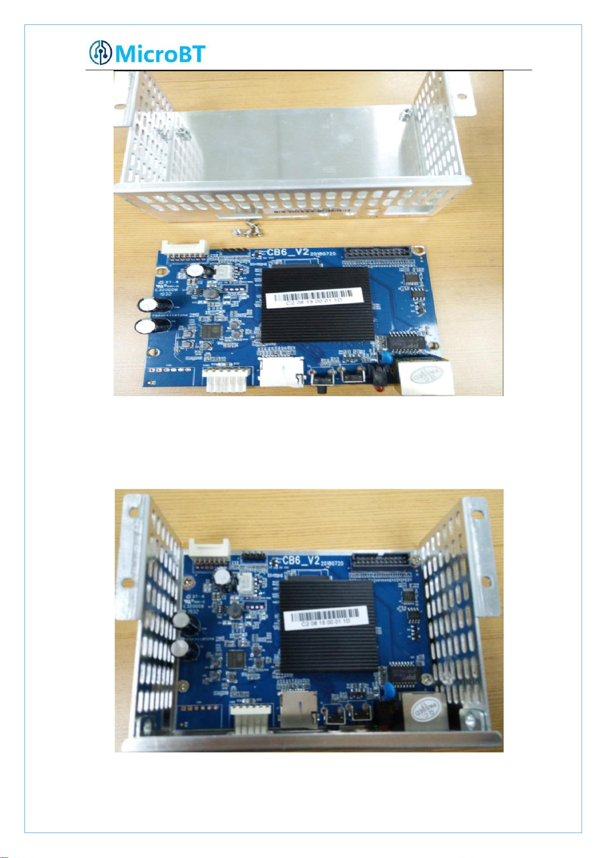
8.1.2.Control Panel Installation
1)When installing the control board, first fix the 4 screws on the control board bracket,
2)Insert the power control cable and the adapter board control cable into the
as shown in the figure:
corresponding slots on the control board, and then fix the bracket to the chassis with

27
screws, as shown in the figure:
3)Plug the fan cable and the control board is installed.

28
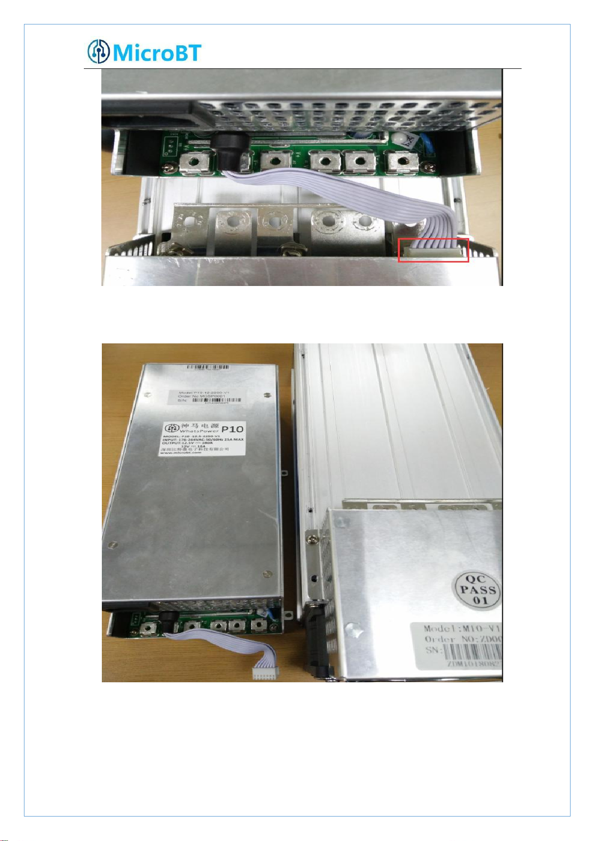
8.2.Power Supply Disassembly and Installation
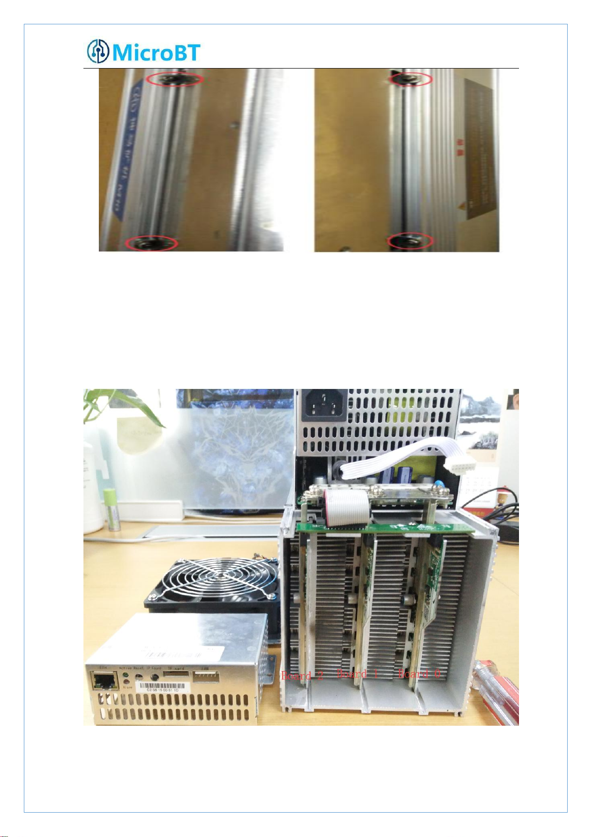
1)Remove the four screws that secure the power supply on the chassis (see Figures 1, 2,
2)After the above operation is completed, gently pull out the power supply (do not pull
8.2.1.Power Supply Disassembly
3, and 4), and then remove the six screws that secure the copper bars on the power
supply (Figure 6). Unplug the fan cable on the power supply (Figure 6).
out too long, the power control cable is still connected to the control panel), as shown in
the figure:
29
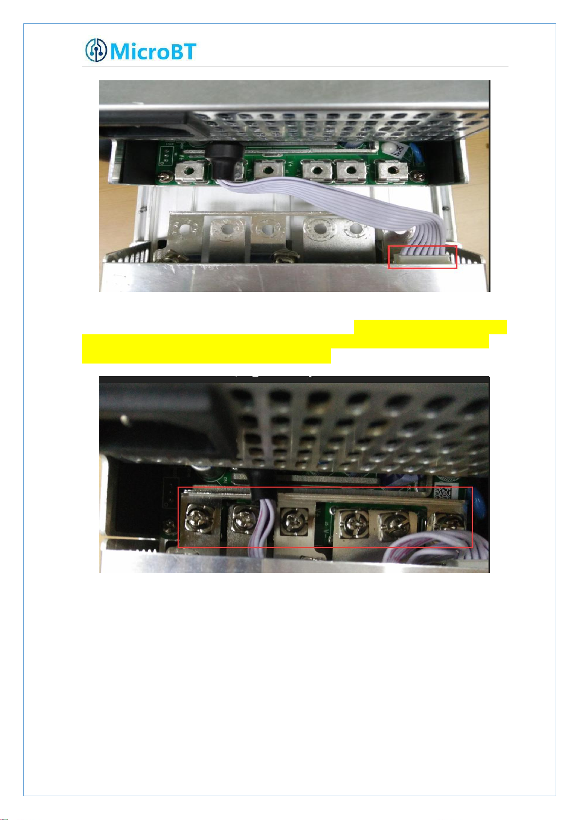
3)Unplug the power control cable on the control panel, remove the power supply, and
remove the power supply:
8.2.2.Power Supply Installation
1)First plug the control cable of the power supply into the corresponding slot on the
control panel, as shown below:
30
2)Then connect the 6 positive and negative terminals on the power supply to the
copper row one by one, and then install 6 screws in turn. The screws should be tightened
3)Finally, tighten the screws of the four fixed power supplies on the chassis, and the
and the gasket should be aligned parallel to the edge of the copper bar to avoid short
circuit burning the power supply or the power board, as shown below:
power supply is installed, as shown below:
31
8.3.Hash Board Disassembly and Installation
1)There are three hash boards on each mining machine (the order number of the hash
2)Remove the adapter plate and the copper bar fixed to the control panel as shown:
8.3.1.Hash Board Disassembly
board is as shown below). Before removing the board, first remove the control board and
the inlet fan, as shown below:

32
3)Extract the faulty hash board outward, as shown:
4)After taking out the hash board, use WeChat “sweep” to scan the power board
serial number and provide it to the relevant after-sales technician, as shown:

33
8.3.2.Hash Board Installation
1)When the hash board is loaded into the chassis, one hand holds the board into the
hash board slot, and sequentially enters the chassis, as shown in the figure:

34
2)After installing the hash board into the chassis, first install the adapter board. The
socket of the adapter board and the pin of the hash board must be installed in place to
avoid other problems caused by contact problems, as shown:

35
3)
After the adapter plate is installed, install the copper bar. When the power busbar is
connected to the hash board, the positive and negative poles of the copper bar cannot
4)After the copper row is installed, the control board and the fan are installed, and
be connected incorrectly, and the screw pads of the fixed copper bar must be aligned
with the edge of the copper bar, otherwise it may be possible to power on. The
machine will be short-circuited and the fixed screws must be tightened to avoid the
normal operation of the machine due to poor contact with the copper bars,as shown:
the hash board is installed, as shown:

36
 Loading...