

Page 1
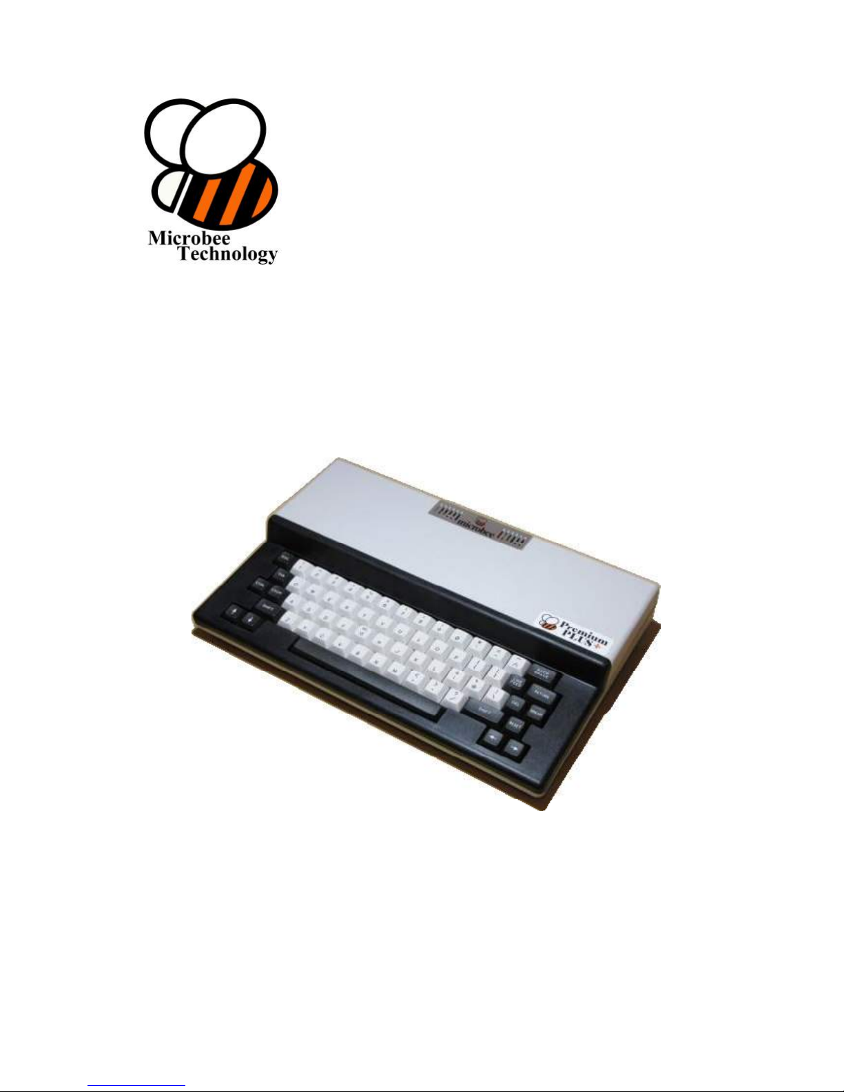
Premium
PLUS +
Construction Manual
Microbee Technology Pty Ltd
Page 1 of 31. Version 1.03 September 2012 Microbee Premium Plus+ | Construction Manual
P.O. Box 709
Lilydale, Victoria
3140
Page 2

Premium Plus+
Construction Manual
Table of Contents
1. Introduction / Requirements ...................................... 3
2. Getting Started - Preparing the Baseboard PCB ........... 3
3. Passive components ................................................... 5
4. Keyboard Frame & Key switch assembly ....................... 8
5. I.C. sockets and PCG ram adapter PCB ........................ 14
6. Integrated Circuits ..................................................... 15
7. Core board Sockets .................................................... 16
8. Completing the Base Board .......................................... 17
9. Final checks & first power up...................................... 19
10. Bill of materials ...........................................................22
11. ‘Check photos’ ...........................................................25
Page 2 of 31. Version 1.03 September 2012 Microbee Premium Plus+ | Construction Manual
Page 3

1.a Introduction
Firstly, Congratulations on purchasing your new Limited Edition Microbee Premium Plus + kit
computer! Whether you have never had a Microbee before, or have been a Microbee fan for
a very long time, we hope that you enjoy the experience of building your own unit and
getting it to do things for you.
As mentioned above, the Premium Plus is a limited edition release with only 105 units being
made available in total. Although we will be designing other Microbee kits in the future, we
will not be re-producing the Premium case, so 105 units is the maximum number of
Premium Plus machines that we can supply. So, to state the obvious, not only do you have
a great kit to assemble & use, but you have a collector’s item as well.
1.b Requirements
Before you get started on the construction of your new Microbee, there are a number of
things that you need to do:
• Read this construction manual completely to see whether you have the knowledge
and skills to complete the assembly & testing of the unit. It is important to note that
once construction has started, the kit cannot be returned for a refund should you
decide that the task is beyond you.
• Check off all of the components against the parts list included at the end of this
manual – if anything is missing from the kit, please contact Microbee Technology via
our website (www.microbeetechnology.com.au) and let us know.
• You will need the following items to construct this kit :
A soldering iron with a good quality tip
Good to very good soldering skills
The ability to identify components & their values (color codes etc..)
Resin cored Solder (there is none supplied with the kit)
A pair of electronics grade side-cutters that facilitate close cutting (ie leaving
very little component leg left at the joint). This is particularly important when
assembling the key switch adapter PCBs.
A Philips head screw driver
A sharp hobby knife
A small pair of pliers
A basic multimeter (measuring DC Volts, and resistance)
Care & Patience!
Provided you follow the instructions in this manual and take time & care in doing so, you
should have a working Microbee very soon.
2.a Getting Started
The first thing to do is to set up a suitable workspace where you will be able to lay all the
components out and have room to assemble, solder and test.
Page 3 of 31. Version 1.03 September 2012 Microbee Premium Plus+ | Construction Manual
Page 4
If you have not done so already, please take the time to check through the component list &
check off each item to make sure you have everything that you need that is supposed to be
supplied with the kit. We do check every kit for completeness, but mistakes can happen, so
its better that you make sure that it is complete before you start construction.
2.b Preparing the Baseboard PCB
You should have a blank Printed Circuit board labelled 8501-4-0CR (this can be found on the
PCB on the component side, rear, right side, near the 5 Pin DIN socket position).
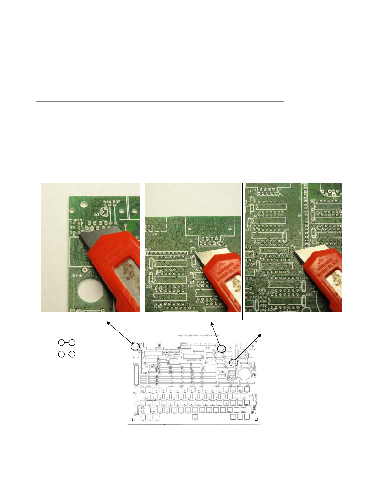
The PCB has a number of configuration ‘jumpers’ on it where the default position is made by
tracks connecting 2 vias (a ‘via’ is a small plated hole in the board that connects top side
tracks to bottom side tracks).
Three of these jumpers have to be cut from their default position and left ‘open’. These are
Jumper W1 position 3 A-B, Jumper W4 1-2 and Jumper W2 1-2 See the diagrams below :
W1 Pos 3 A-B
< Before
< After
Be very careful when you are making the cuts not to slip and cut another track. It is more
controlled just to ‘take a little divot’ out of the track between the 2 vias, using the sharp
Page 4 of 31. Version 1.03 September 2012 Microbee Premium Plus+ | Construction Manual
W4 1-2
W2 1-2
Page 5
hobby knife in a twisting / digging way rather than trying to slice through the track. Now we
are ready to start placing the components onto the board.
3. Passive components
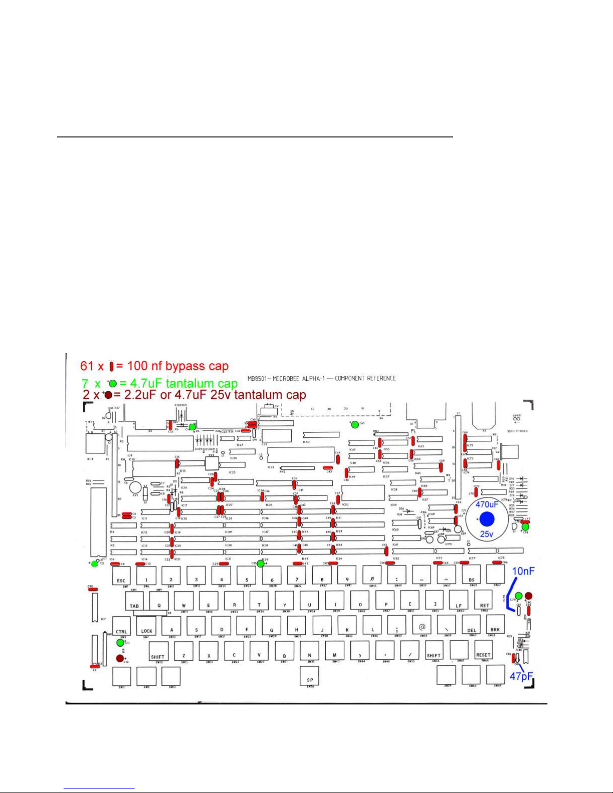
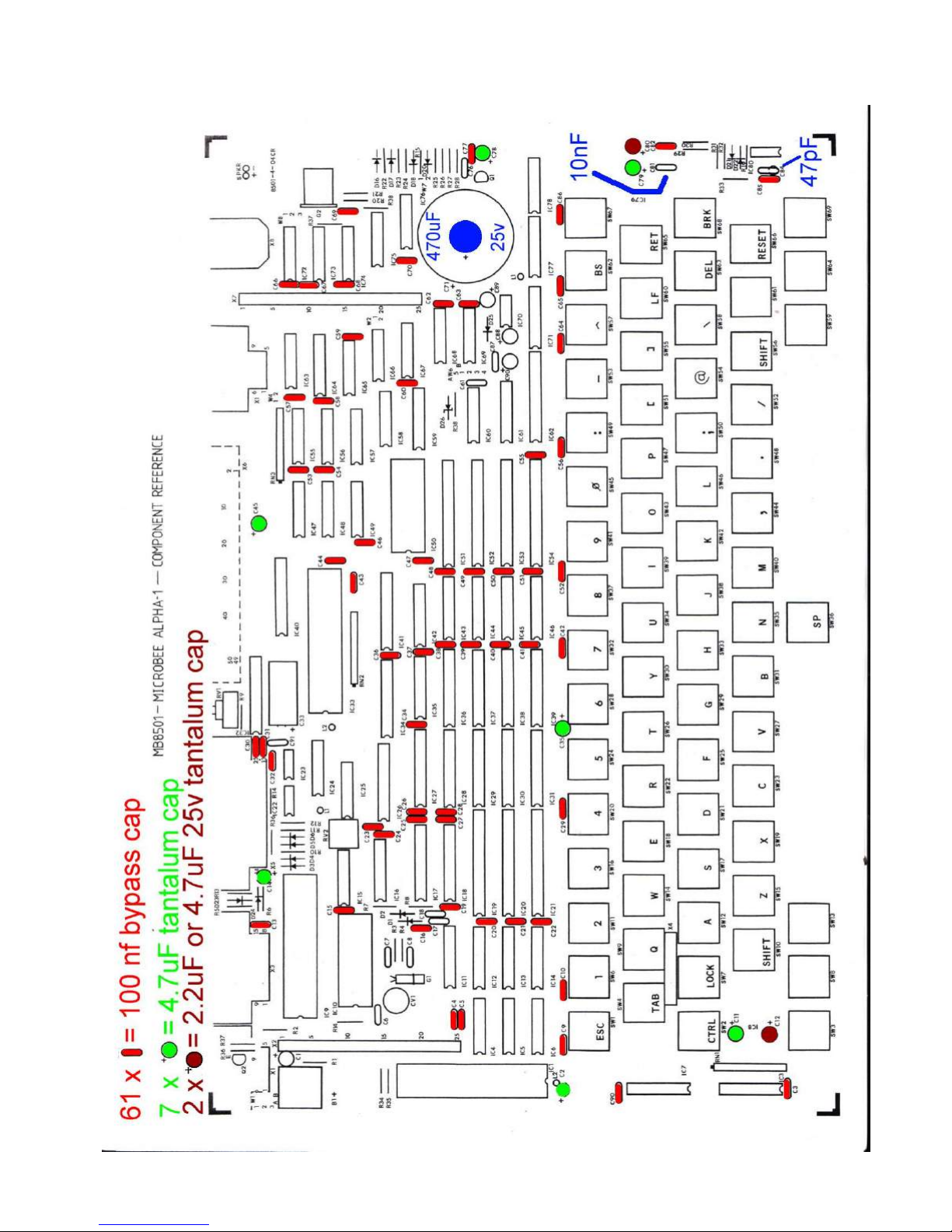
We shall start placing components by starting with the capacitors. There are only 5 different
types / values of capacitor on the board and they are as follows :
61 x 100nF bypass cap (supplied on a tape)
7 x 4.7uF 16v Tag Tantalum cap [Polarised], 2 x 4.7uF 25v Tag Tantalum cap [Polarised]
1 x 10nF cap (single, on tape)
1 x 47pF cap (single, on tape)
1 x 470uF 25v Electrolytic cap [Polarised]
You can do these in any order, but take care with the polarised components that you insert
them so that the ‘+’ marking on the component is on the same pin side as the ‘+’ marking
on the white component legend on the PCB. If these are inserted the wrong way around,
they can explode when power is applied.
Please refer to the ‘stuffing diagram’ below showing where each capacitor is to be placed.
With the components supplied on tape, it is easier to cut the legs of the components at the
edge of the tape rather than try to remove (unstick) them from the tape. This still leaves
enough component leg left to effectively solder them into the PCB and trim them once done.
Page 5 of 31. Version 1.03 September 2012 Microbee Premium Plus+ | Construction Manual
Page 6
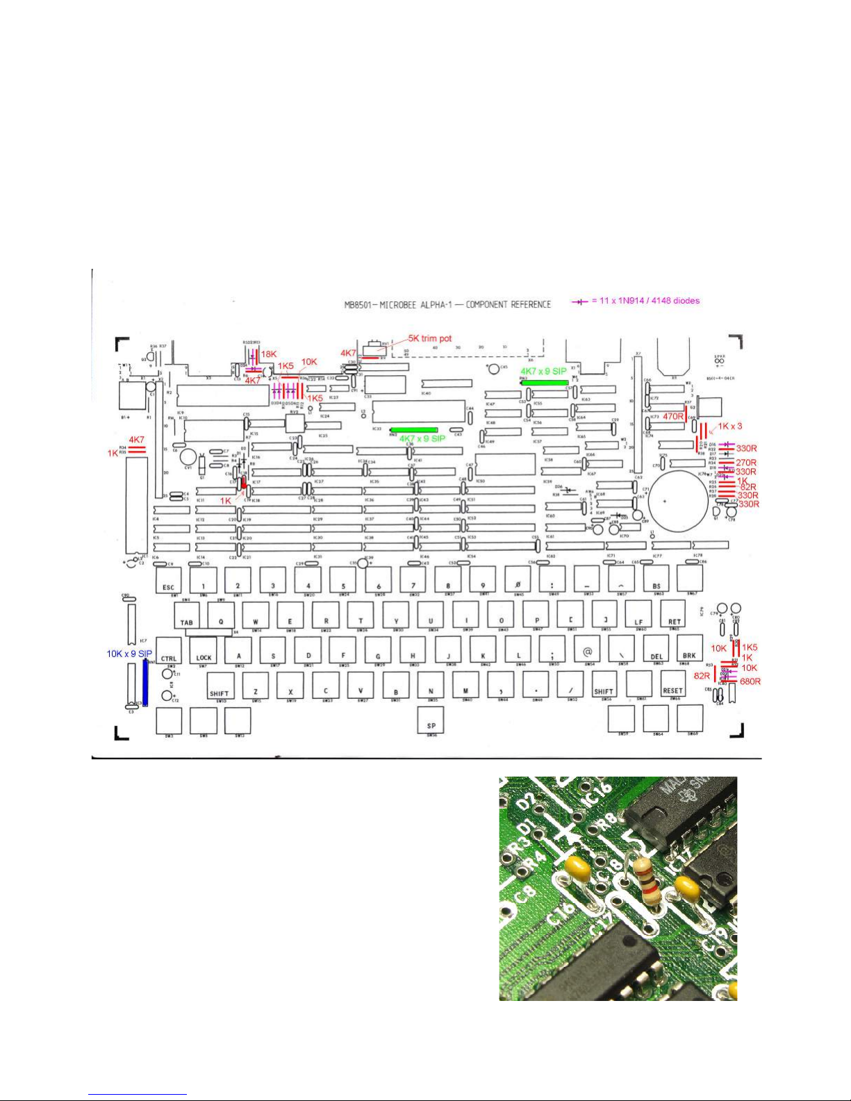
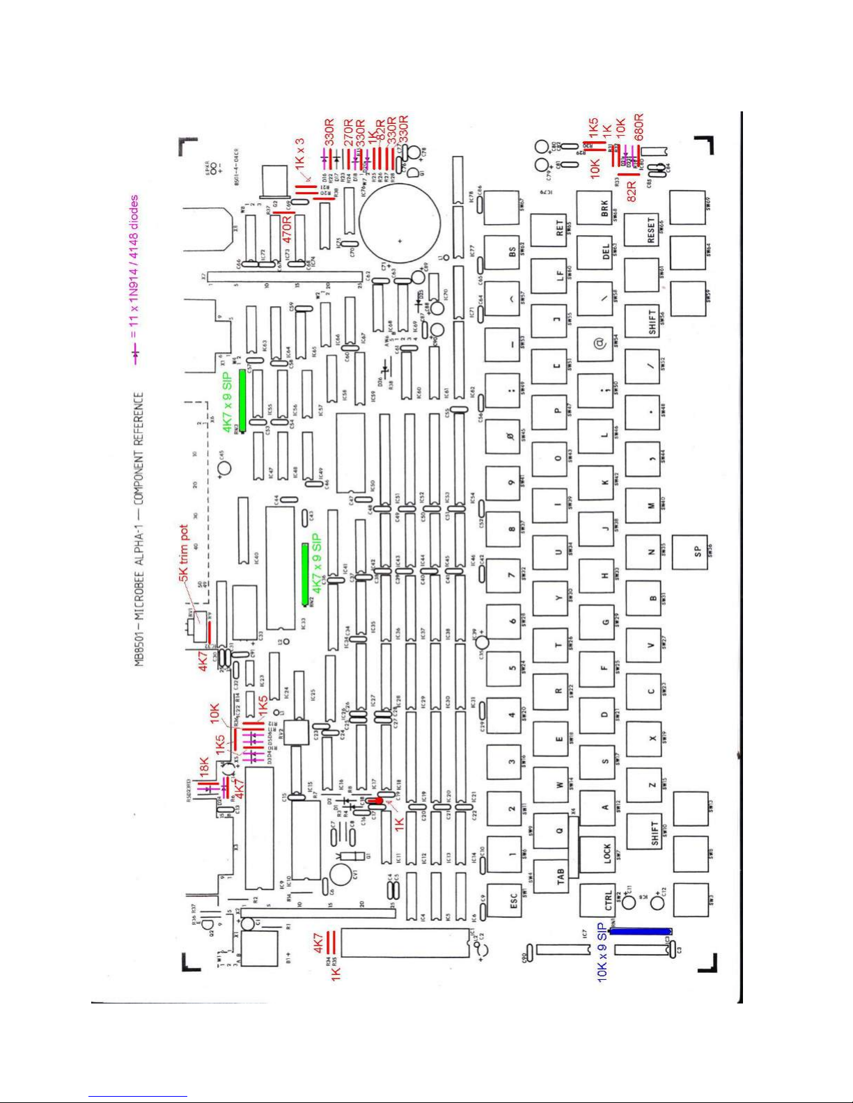
Next we shall place all of the resistors and also the small signal diodes.
Referencing the marked up component overlay below, work through the resistors section of
the parts list which gives values & component reference designators, ticking off each
component as you go. The resistor SIPs (Single Inline Package) are 9 resistors in one
package with all of those resistors connected to a common pin. If you have a look at the
SIP, the value is written on one side (472 = 4.7K, 103 = 10K) and the dot at the left end
signifies pin 1. Make sure you line up pin 1 with the marking on the PCB.
Mounting the 11 x 1N914 / 4148 diodes is straight forward but make sure the band on the
body of the diode matches the polarity shown on the component legend.
Note also that one of the resistors gets mounted
at position ‘C18’. The Premium was originally
designed to have an LM386 integrated amplifier
as its speaker driver and C18 was part of the
coupling into the amplifier, however, the LM386
amp was very noisy – even when there was no
sound being output from the Microbee, so the
LM386 circuit was replaced by a basic onetransistor speaker driver like the original
Microbees had. A 1K resistor gets mounted
vertically in the C18 position as part of this
circuit. See the photo opposite.
Page 6 of 31. Version 1.03 September 2012 Microbee Premium Plus+ | Construction Manual
Page 7
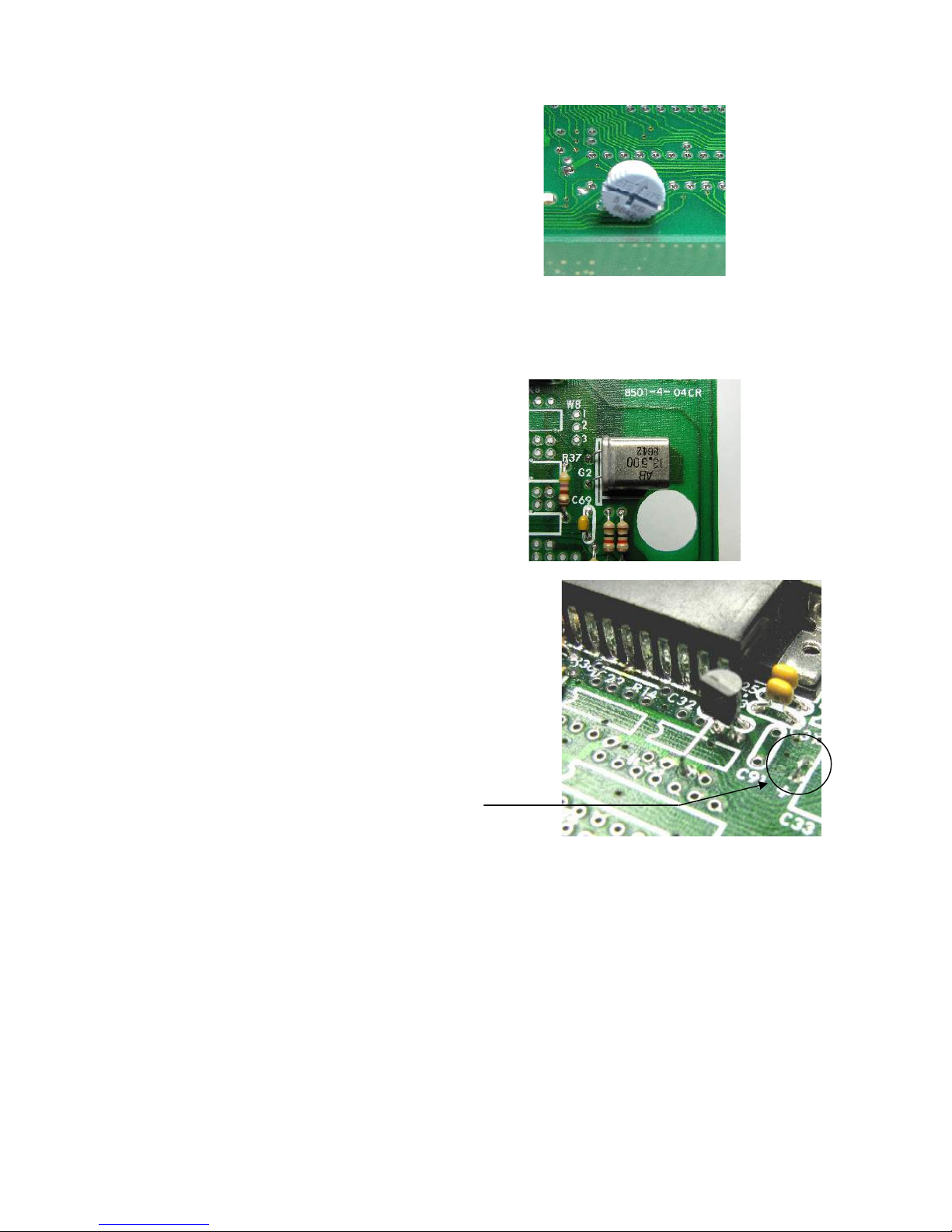
The speaker volume control (RV1)
is a 5K ohm trim pot which gets
mounted on the under side of the
PCB and soldered on the top side.
See the photo opposite which
shows the PCB upside down with
the trim pot facing the edge of the
board.
At this point there are just the 2 transistors & 1 crystal to mount on the board.
Transistor Q1 is mounted on the PCB just as the component legend shows. The middle leg
(the BASE) will need to be bent out a little to fit into the PCB.
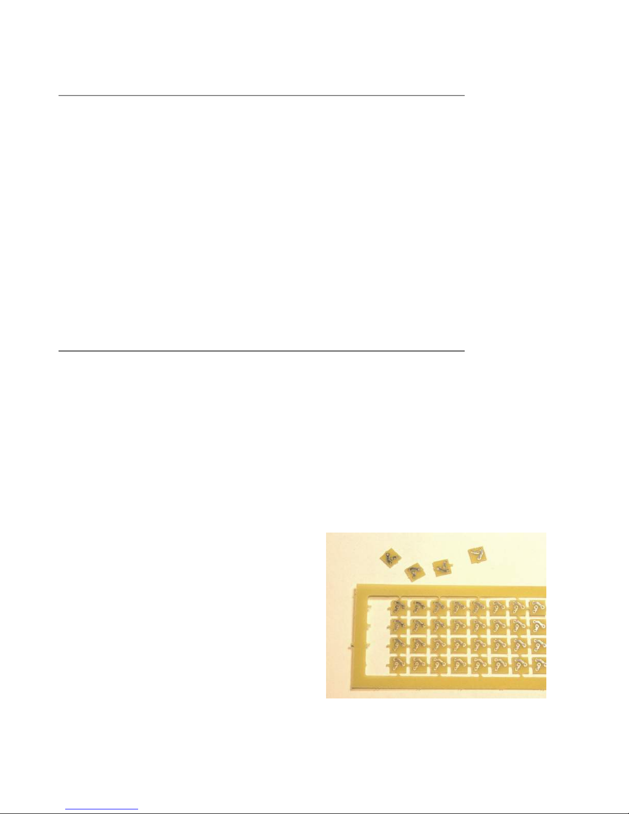
The 13.5Mhz crystal lays flat
(horizontal) on the PCB and needs
to be located a little bit backward
from the hole in the PCB for the
case post.
This means that the component
legs have to be lead-formed with
an offset as in the picture to the
right.
The speaker driver transistor (a BC548) gets
located at what was the LM386 location – IC23.
As you can see from the photo opposite, the
Emitter & Collector of the transistor go into pins 5
& 6 of the IC location, and the BASE lead gets
bent backwards & is soldered into IC23 – pin 3.
Note that the round side of the transistor is facing
toward the edge of the PCB.
Also, a LINK is needed between the + & terminals at the C33 component location as
shown in the same photo.
LINK
Having installed all of the passive components now, there are a few IC’s to insert before we
can start mounting the keyboard frame & regulators. IC3 (a 74HC151) and IC7 (a 74LS156)
form part of the keyboard scanning circuit & are located in the area that the keyboard frame
covers once assembled, so it is a good idea to solder these in now. Likewise, IC80 (a
CA3140 op amp) on the right side of the board, should be soldered into place now.
Connectors at the rear of the board can be soldered in at this point. Once the keyboard
frame is in place (in the next few steps) the board will need to be powered up to check the
operation of the 2 regulators, so having (at least) the power connector fitted will be
essential. After the connectors are installed, you can refer to ‘check photo 6’ at the end of
the manual and the board being assembled should look the same as the photo.
Page 7 of 31. Version 1.03 September 2012 Microbee Premium Plus+ | Construction Manual
Page 8
4. Keyboard Frame & key switch assembly
The Microbee Premium Plus keyboard is made up of a number of parts which includes
individual mechanical key switches, key tops (caps), a metal keyboard frame and key switch
adapter PCBs. In planning and designing the Premium Plus, large efforts were made to try
and procure key switches that were the same physical form as the original ones. There was
no exact match to be found. Some came close (like the Cherry brand MX series) but were
cost prohibitive, others had non-suitable shaft styles and so on. All of the key switches that
we looked at also had different pin spacings & locations as well. While we could have
scrapped the existing stock of Premium series baseboards and made new ones to suit a
different style of switch, this was deemed to be wasteful & expensive. Seen as the Premium
Plus is a limited edition kit, the best solution was to provide a small adapter PCB for each of
the new key switches, so that the assembled switch would then suit the original PCBs. This
also made the solution suitable for people who want to replace the keyboard in other
Microbee models.
4.a Key switch assembly
Assembly of all of the key switch adapters & fitting them to the key switches takes quite an
amount of time. You can expect to spend 2 hours working through the whole lot of keys, so
have some patience & take a break when you need to because it is better to spend as much
time as it needs to do a great job rather than rushing it through. If done well, you will have
a decent keyboard for your Microbee that will last well. If you rush in assembling them, it is
likely that you will have keys that don’t work as well as they should.
In your kit, you will have a bag specifically of keyboard bits. This includes the key tops, key
switches, gold PCB pins, mounting hardware and so on. There is also a PCB supplied that
has 68 (64 needed, plus 4 spare) key switch adapter PCBs in a frame.
All of the individual adapter PCB’s are held
together in the frame with breakout tabs.
That is, on the edges of each PCB there is a
little bit of PCB material that connects one
PCB to another to hold all of them in the
frame while the board is being manufactured.
At these points there are very small holes
which provide a breaking point. If this point
is flexed, it will break apart & each individual
PCB will come away from the others. Refer to
the photo to the right which shows some of
the key switch adapter PCBs broken out from
the frame.
Page 8 of 31. Version 1.03 September 2012 Microbee Premium Plus+ | Construction Manual
Page 9
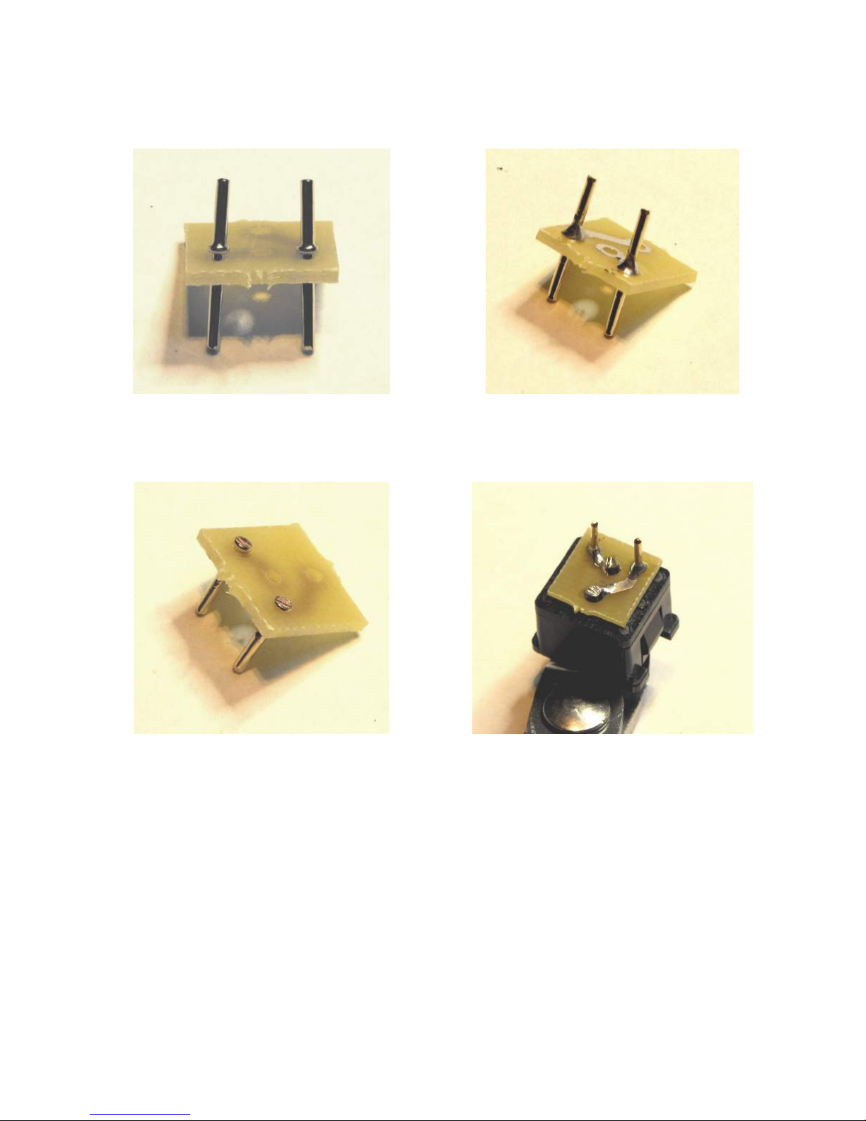
The following shows the general procedure for making up and fitting the key switch adapter
PCBs to the key switches.
1. Insert the PCB pins from the non-track
side of the PCB, with the longer section of
2. Solder the 2 PCB pins in place with a nice
triangular fillet or even slightly concave.
the pin through the hole.
3. Trim the excess pin length as close as
possible without removing the collar (this
locks the pin into the PCB and stops it from
falling out when the pin is soldered into the
main PCB later
4. Solder the finished adapter onto the back
of a key switch. Make sure that the adapter
is flat against the back surface of the key
switch. This is important as we do not want
any ‘slack’ or chance of pressure on the pins
of the switch. If the pins of the switch get
pushed into the body, the switch will not
work properly.
Note that in step 4, the adapter PCB will be at a slight angle if correctly installed as the
collars on the PCB pins will keep it from sitting absolutely flush. This is o.k.
The whole procedure is quite fiddly and it is tricky to ensure that the pins are upright and
parallel to each other (and hence keeping the same spacing). The following photos (on the
next page) show a setup that makes the job easier & more accurate.
Page 9 of 31. Version 1.03 September 2012 Microbee Premium Plus+ | Construction Manual
Page 10
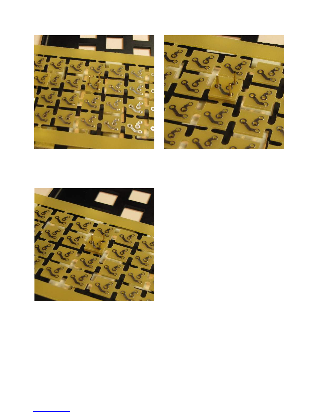
1. With the PCB adapter board spread across
the up-turned keyboard frame, insert 3 PCB
pins (short end through the holes)
3. Solder the 2 required pins, leaving the 3rd
un-soldered, and then remove the adapter &
trim the pins as described earlier.
2. Place a ‘broken-out’ adapter on top so that
it is then sitting on the collars of the PCB
pins (using 3 pins keeps the adapter PCB
level)
Obviously, as you do more and more of the
adapters, the PCB frame will have less and
less adapters in it and the last few will
probably have to be done with no support
from the frame.
One other tip is that if you line the adapter
that you are working on up over a key switch
hole in the keyboard frame below it, you can
press down on the centre of the adapter so
that it ensures that all of the PCB pins are
pressed ‘up’ against the bottom of the
adapter as you solder it. This also aids in
making sure the pins are straight & parallel.
There is a bit of a ‘knack’ to doing this, but
after doing a few, you should see it get
easier.
Remember that only 64 key switches are
needed, so the last 4 adapters in the frame
do not need to be assembled.
Page 10 of 31. Version 1.03 September 2012 Microbee Premium Plus+ | Construction Manual
Page 11
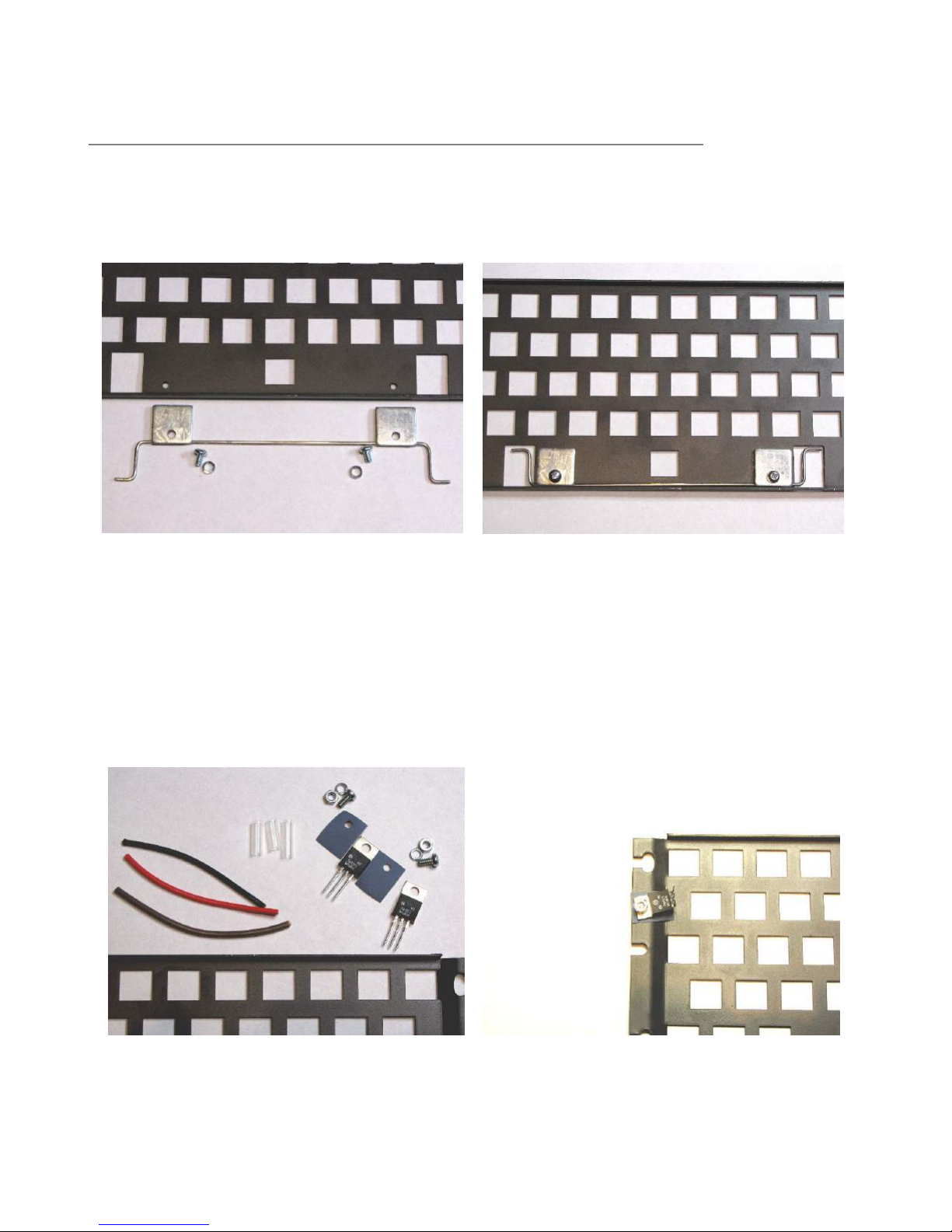
4.b Keyboard frame assembly & mounting
Lay the keyboard frame flat on your work surface with the top side facing down.
The torsion bar for the space bar key has to be installed before the keyboard frame is in
place on the PCB, otherwise it is very difficult to install.
This picture shows the parts required – the
torsion bar, 2 clamps & bolts with spring
washers.
Mounting the 2 x 7805 5volt regulators is next. Both regulators bolt directly to the keyboard
frame underside with a thermal transfer silicon-rubber pad. The regulator for the right hand
side [eventually] gets soldered directly to the main PCB. The regulator on the left hand side
of keyboard however requires short wires to be attached which then get soldered into the
main PCB. This is due to the lack of space on that side of the keyboard frame (having part
of the keyboard scanning circuit on the main PCB at that point).
The torsion bar is now in place held into the
corner of the keyboard frame by the clamps
which are bolted into threaded holes in the
keyboard frame.
The parts required – 2 x 7805’s, thermal
washers, nuts, bolts, spring washers, wire
and heat shrink tubing.
Page 11 of 31. Version 1.03 September 2012 Microbee Premium Plus+ | Construction Manual
The right hand side regulator (it’s on the
left of the keyboard frame in this ‘upside
down’ view) gets mounted at a slight angle
with its legs bent up at right angles.
Page 12
When fitting up this regulator, bolt it down but do not tighten the bolts too much. At this
stage we want the regulator to be held firmly in place, but to be able to adjust the position
of it and get the right angle to allow the legs to meet with the holes in the main PCB where
it is to be soldered in. This will take a bit of fiddling to get everything to line up.
It is advisable at this point to sit the main PCB in the bottom half or the case so that you can
position the keyboard frame correctly over the main PCB while taking into account the
mounting position of the keyboard frame into the case bottom. Once you have the regulator
set up to that the pins line up with the holes in the PCB, you can tighten the bolts to keep it
that way. Do NOT solder the regulator to the PCB at this time.
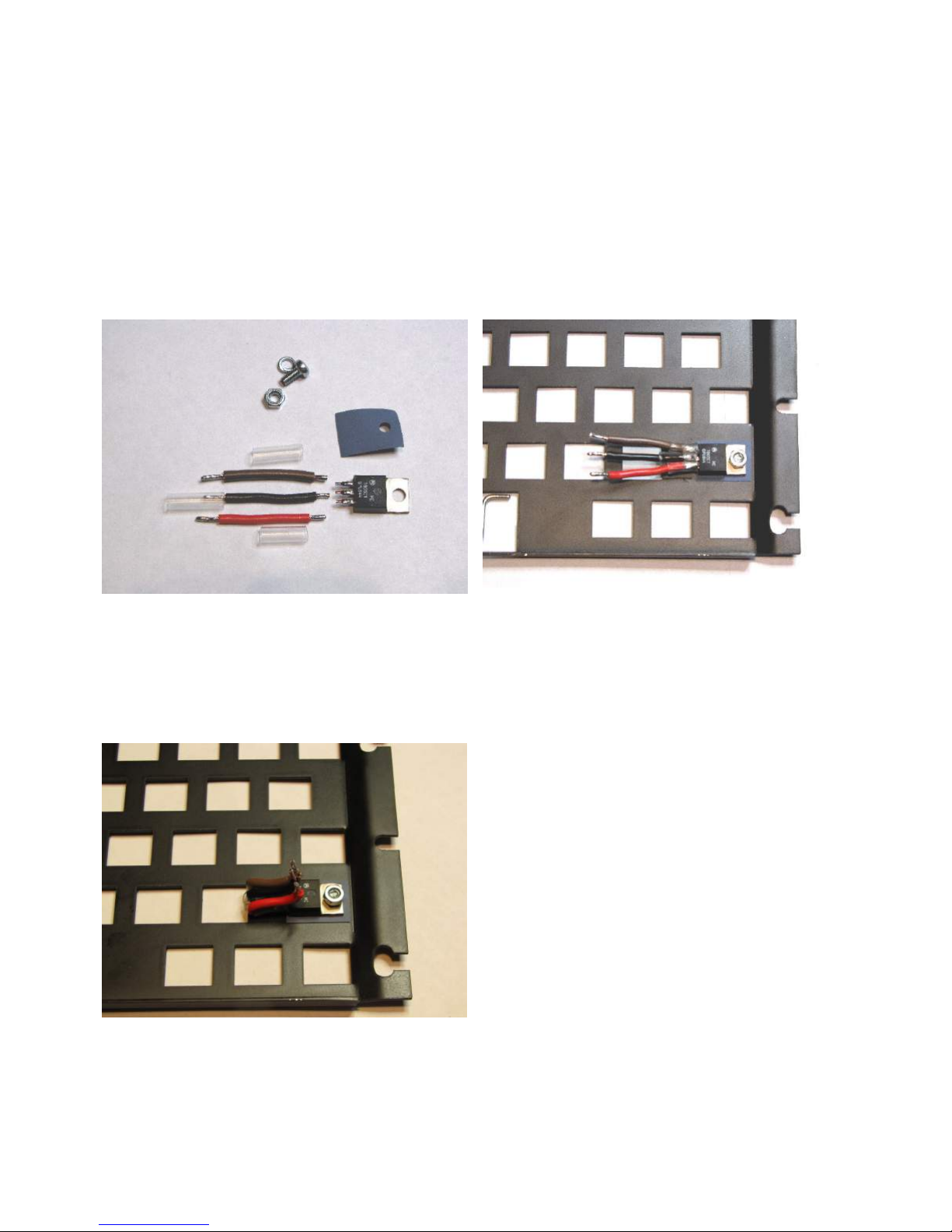
The left hand side regulator…
Trim the legs back to just near the wider
part of the leg. Also, prepare 3 wires about
30mm long and tin the ends.
Mount the regulator with the thermal pad,
nut, bolt & spring washer as shown. Solder
the wires on & slide the heat shrink tubing
onto each so that the joints are insulated
from each other. The tip of the soldering
iron will shrink the tubing.
Next, the wires that you have just soldered
to the regulators’ pins need to be bent up
as shown in the photo.
These wires will connect the regulator to
the main PCB – they are essentially
extending the legs of the regulator so that
they reach the correct position and can be
soldered in.
You may need to trim the width of each
wire a little so as to be able to fit the ends
of the wires through the holes in the PCB in
the pads for the regulator position.
Page 12 of 31. Version 1.03 September 2012 Microbee Premium Plus+ | Construction Manual
Page 13
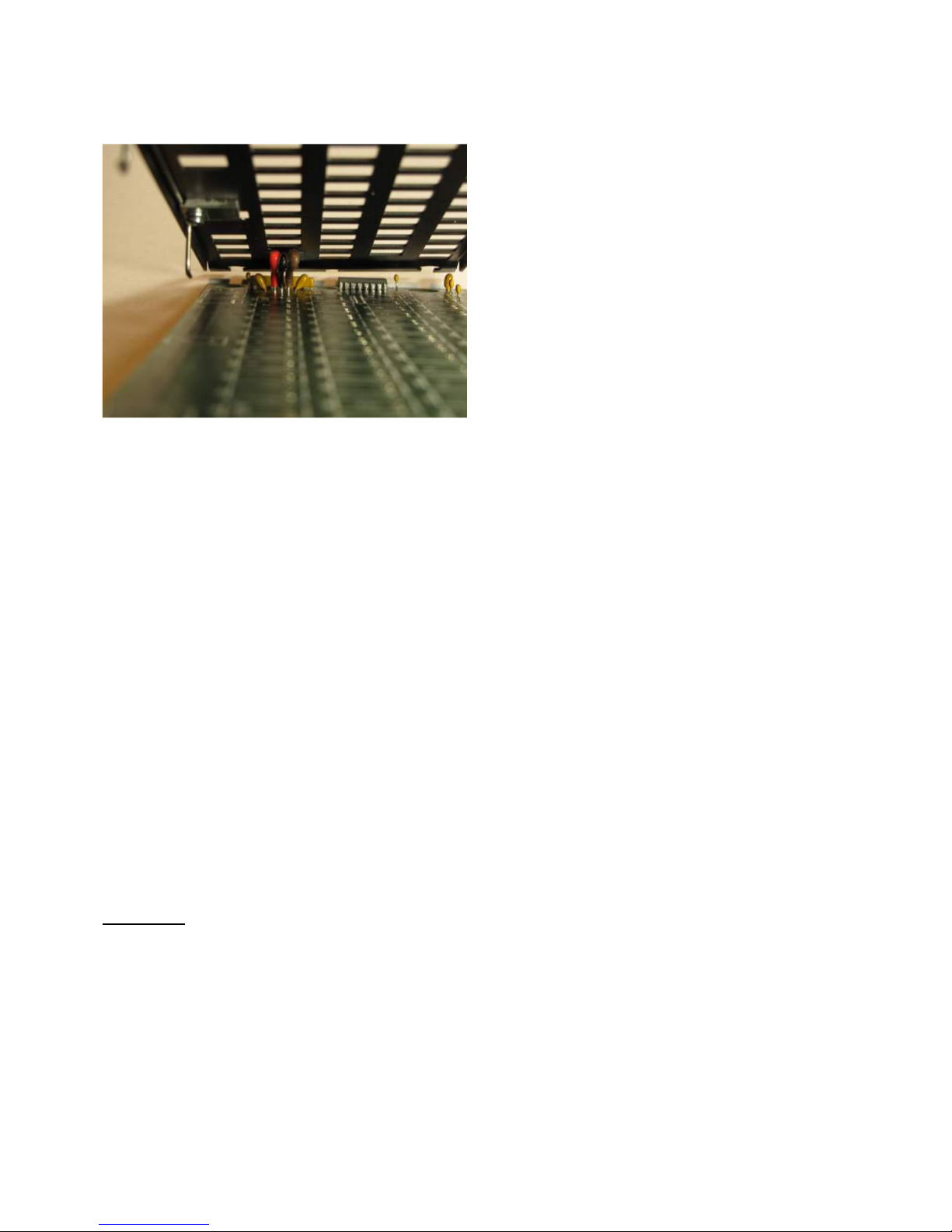
Soldering the regulators into the main PCB..
Ensure that the wires attached to the
regulator fit through the pad holes & then
solder all three into the main PCB.
As shown in the photo to the left, the wires
line up in order with no need to cross any
over.
This is the same as having the regulator
pins bent at right angles toward the PCB &
soldered in.
Now, before the other regulator gets soldered into place, the positioning and height of the
keyboard frame (with respect to the main PCB) needs to be correct.
It is at this point that some key switches are needed to be placed into the frame.
To start with, just 5 keys are needed – in the ‘outer most’ positions on the keyboard where
the ‘ESC’, ‘Backspace’, ‘Up Arrow’ and ‘Right Arrow’ keys are found. The ‘Space bar’ position
is also used. Once again, it is easier to align the position of the keys if the main PCB and
the keyboard frame is sitting in their correct positions in the base of the case.
Inserting the key switches into the frame will require a reasonable amount of force as they
are a tight fit. Watch to see that the PCB pins on the adapter of each key switch go through
the holes in the main PCB as they should. Once the 5 key switches are in the frame,
carefully lift the frame & main PCB out of the bottom of the case, ensuring that it all stays
together and then ‘tack’ solder 1 pin of each key switch. This is a bit of a juggling act but
can be achieved by holding the PCB and frame on one side, while soldering the pins.
Do not apply too much heat to the pins while soldering them as this will melt the solder
that holds the pins in place in the adapter.
Once the five key switches have been ‘tacked’ in place, the keyboard frame can be checked
to see if it is positioned well and that the height from the PCB to the keyboard frame is the
same on all sides. Typically, the PCB pins of each key switch should protrude through the
PCB by around 2mm. Once the keyboard frame is all level, the right hand side regulator can
be soldered into the main PCB.
Initial test
Now that the regulators are soldered into place, it is a good idea to check to see if there are
any shorts & whether the two 5 volt power rails on the main PCB work as required. If
something is not right at this point it is easier to get to the regulators than when the full
keyboard is assembled.
First check that there are no short circuits.
With a multimeter set to low ohms range, check the following points on the PCB:
a) across the main input capacitor (C71) – you should see an initial low ohms reading
due to the charging of the capacitor (by the multimeter), but after a small amount of
time, this should be a large resistance value. As long as it is not permanently below
10 ohms, then all is well.
Page 13 of 31. Version 1.03 September 2012 Microbee Premium Plus+ | Construction Manual
Page 14
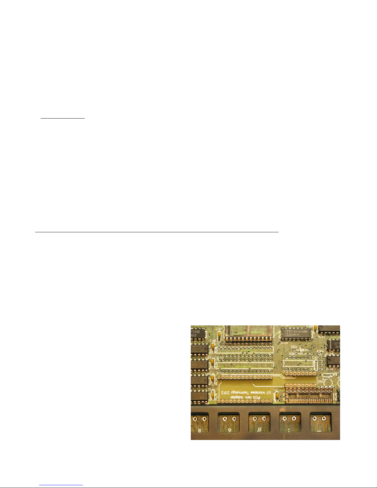
b) across IC16 pins 8 & 16 – this should be a fairly large resistance value and represents
the output side of one of the 5volt regulators. Once again, as long as it is not
permanently below 10 ohms, then all is well.
c) across IC72 pins 7 & 14 – this should be a fairly large resistance value and represents
the output side of the other 5volt regulator. Once again, as long as it is not
permanently below 10 ohms, then all is well.
If you find any shorts in the above steps, check over your soldering work – particularly at
each regulator and correct these before moving on to the next steps.
Power on test
The Microbee Premium Plus runs with an input power supply of 10 – 14 volts DC which is fed
into the main board via the 5 pin DIN connector. 10 Volts is preferred as the regulators will
run cooler.
With the multimeter set to measure D.C. volts and a suitable range selected to measure the
10 – 14 Volts D.C., apply power and quickly measure the input voltage across C71 to
confirm that the power supply is getting to the board o.k.
Measure the two 5 volts rails at:
a) IC16 – negative meter lead to pin 8, positive to pin 16 – should read +5.0v +/- 10%
b) IC72 – negative meter lead to pin 7, positive to pin 14 – should read +5.0v +/- 10%
If these are measured o.k. then construction can continue and the un-soldered pins on the 5
key switches can now be soldered.
5. I.C. sockets & PCG ram adapter PCB
Sockets have been supplied in the kit for the larger logic devices including the CPU, PIO,
6545, the Font ROM, the Screen RAMs and the Gold PAL. These can be soldered onto the
PCB now.
There are 3 x 40 pin sockets for locations IC1, IC9 & IC33.
There are 3 x 24 pin (skinny) sockets for locations IC19, 20 & 21. Note that these locations
are actually for 28 pin parts and the 24 pin sockets get soldered into the PCB so that pin 1 of
each socket gets soldered into the pin 3 location on the board – i.e. the left-most 4 pads
(pins 1,2, 27 & 28) are left empty.
There is 1 x 24 pin (skinny) socket for location IC62.
There is 1 x 24 pin (normal width) socket for location IC50.
The original Microbee Premium Series
computers were supplied as standard with
16k bytes of Programmable Character
Generator (PCG) memory. The Premium
baseboard was designed for a maximum of
32K bytes of PCG memory however and the
Premium Plus kit includes this as standard.
To implement the full 32k, we have
designed a small adapter PCB that takes a
single 32k x 8 bit static ram rather than the
4 individual 8k x 8 bit static RAMs in the
original design. The adapter is pre-made
and has to be soldered into the baseboard.
The PCG ram adapter board fits onto the
baseboard at IC locations IC53/4 and IC61.
Page 14 of 31. Version 1.03 September 2012 Microbee Premium Plus+ | Construction Manual
Page 15

The pins of the PCG ram adapter PCB do not quite protrude through the other side of the
baseboard PCB, however, there is enough of the pin in the pad holes that they can still be
soldered by ‘flooding’ the hole with solder. Apply just enough solder for it to ‘wick’ down the
hole and surround the pin so as to get a good solder joint.
6. Integrated Circuits.
Now it is time to start installing the integrated circuits.
Start with all of the smaller 14 & 16 pin devices. Take care that each is located at the correct
IC location. Check as you go that the correct device for that location is being installed by
cross referencing the parts list. The ICs are supplied on a sheet of anti-static foam with a
component reference overlay on it.
* Handy Tip * When installing all of the ICs, solder just 2 diagonal pins to start with. For
example, on a 14 pin device, solder pin 7 & pin 14 to the board & leave the rest for now.
Then, once all ICs are in position and verified for correct type & orientation, solder the rest
of the pins for each device. This way, if you make a mistake and (say) put a device at the
wrong location, it is easy to remove the device and make the correction.
While it is possible to use IC sockets for all of the devices, it is not recommended as, over
time, socket contacts oxidise and the circuit performance can be degraded.
Next, move onto the larger 20 pin devices. Install these in the same manor, checking that
the location and device types are correct, along with making sure of the proper orientation.
It is a good idea at this point to do a thorough visual inspection of your soldering and check
for any component leads that may be shorting. As quite a few of the ICs are close together,
it is common for the legs of adjacent components to touch each other on the under side of
the board. Trim any leads that are close to each other to ensure no shorts can occur.
Page 15 of 31. Version 1.03 September 2012 Microbee Premium Plus+ | Construction Manual
Page 16
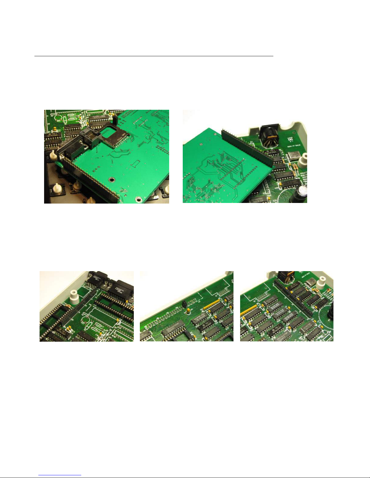
7. Core board sockets.
There are 3 sockets that need soldering onto the baseboard PCB for connection to the core
board. There are two 25 way socket strips and one 2way socket header that must be
installed. The easiest way to get these connectors into the correct position and ensure that
they are upright is to use the core board as a guide with the sockets plugged onto the pin
strips.
Right side 25 way strip + 2 way socket
Left side 25 way socket strip
Put the core board in location on the main board & ‘tack’ the 2 outer most pins of each 25
way socket strip first. Check that the sockets are as close to the PCB as possible and that
the 2 way socket is in its location at pins 13 & 14 of the 50 way connector position – X6.
Once satisfied that everything lines up correctly, solder the rest of the pins on all 3 of the
socket strips and then remove the core board.
Page 16 of 31. Version 1.03 September 2012 Microbee Premium Plus+ | Construction Manual
Page 17
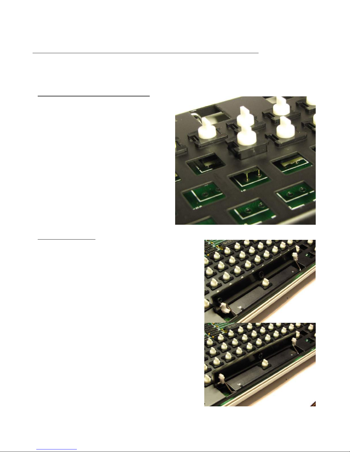
8. Completing the Baseboard.
The final steps in completing the construction of your Microbee Premium Plus baseboard
involve completing the installation of the key switches, fitting the key tops, fitting the
socketed components and wiring up the speaker.
Installing the rest of the key switches
Start from the front most row when
fitting up the remaining key switches.
This enables you to look down through
the keyboard frame from the rear so
that you can see the pins of the key
switch and line them up with the holes
in the pads on the PCB. Note that the
front most row only has 5 keys and has
2 spare switch positions closest to the
space bar. As you solder the key
switches in, remember to apply just
enough heat to melt the solder and
form a decent joint on the PCB.
Applying prolonged heat to the key
switch pin will melt the solder on the
switch adapter and if excessive heat is
applied, the pin may lodge itself in the
underside of the key switch.
Fitting the key tops
Fitting the space bar requires several steps :
Two white space bar support mounts have
been included in the keyboard kit. These fit to
the bottom of the space bar & have slots in
them to take the ends of the torsion bar.
This arrangement helps to keep the space bar
level when pressed somewhere off-centre.
Fit one of these to one side of the space bar as
shown in the top picture to the right.
Slide that end of space bar with the support
onto the torsion bar, add a support to the
other end of the torsion bar & then fit the
support into the bottom of the space bar.
Now that the space bar & mounts are fitted to
the torsion bar, the space bar can be pushed
down onto the key switch and fitting the space
bar is done.
Page 17 of 31. Version 1.03 September 2012 Microbee Premium Plus+ | Construction Manual
Page 18
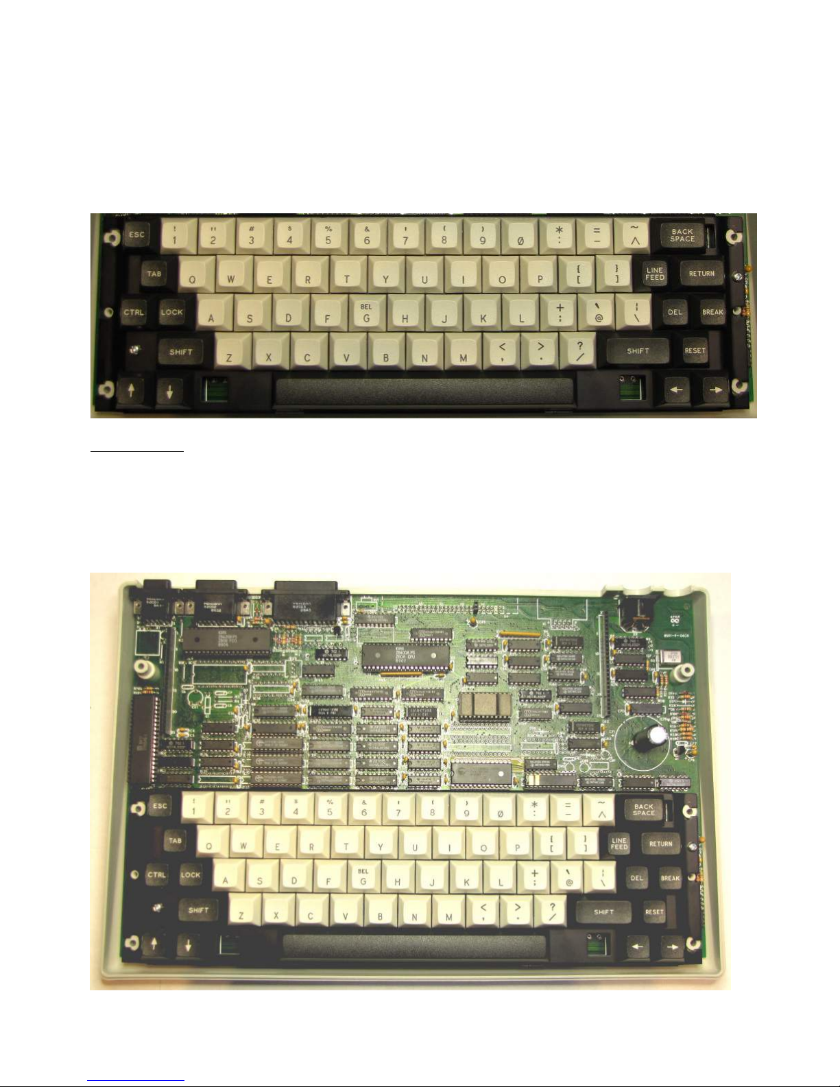
Fitting the rest of the key tops is straight forward. Note that the arrow keys can be
interchanged with each other unlike the original key top set in which the up arrow, down,
left & right arrows were all specific to a particular position.
The original keys had a ‘high side’ and ‘low side’ (i.e. they were an angled / sculpted design)
whereas the new key tops are uniform in shape.
When finished, the keyboard should look like the picture below.
Socketed ICs
All of the remaining ICs can now be put into their sockets. Pay attention to the orientation,
checking where Pin 1 should be located for each as you plug them in.
The ICs that are socketed are as follows:
IC1 – 6545, IC9 – Z80APIO, IC33 – Z80ACPU, IC50 – Font ROM (2532),
IC19,20 & 21 – CY7C128A, IC53/4 - CY62256 SRAM, IC61 – 74HC139 and
IC62 - the GOLD PAL
Once done, the baseboard should look like the one in the following photo.
Page 18 of 31. Version 1.03 September 2012 Microbee Premium Plus+ | Construction Manual
Page 19
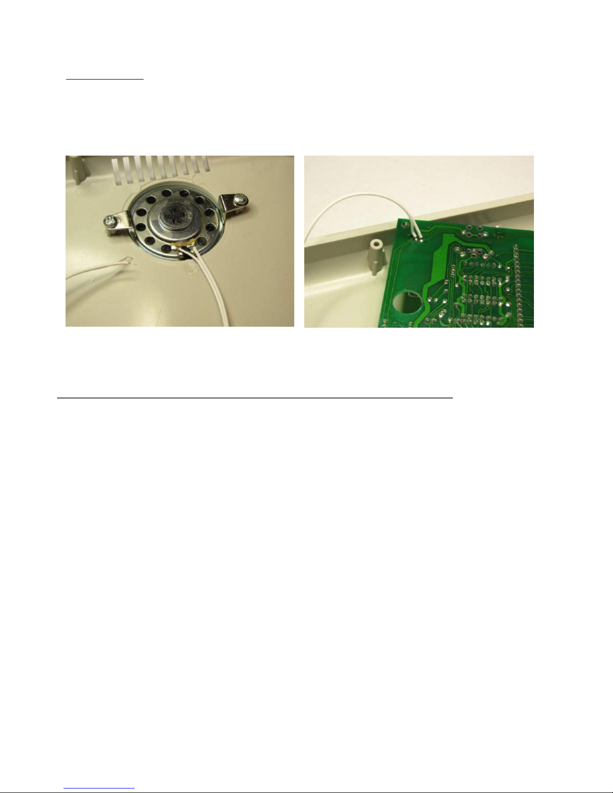
Speaker wiring
The speaker should already be in place in the bottom of the case held in with its metal
clamps & screws. Wiring is straight forward with the 2 core bell wire supplied. Strip both
ends of the wires, tin them with the soldering iron and attach to the speaker and baseboard
as shown in the photos below. The volume control for the speaker should be set at the mid
way point of its travel now.
Tinned Bell wire attached to the speaker Speaker cable connected to the under-side
of the PCB near the 5 pin DIN socket.
9. Final checks & first power up.
Now that all the components are soldered into the baseboard, it is time for final visual
inspections, checking for shorts and un-soldered pins, component orientation mistakes,
polarised capacitors & diodes the wrong way around and so on.
The check that was carried out earlier with the multimeter can be done again in checking for
a short across the input power rail at C71, not that much should have changed in that area
since the previous check. It is however a simple test & easy to carry out, so best to do it
anyway. The voltage checks can also be done, without the coreboard installed, to ensure
that the two 5 volt power rails still provide the required voltage.
Without the coreboard plugged in, the system will not do anything, so don’t expect to hear a
beep or get video on the display – we just want to measure the power rails again.
Once done, remove power from the baseboard.
If all looks good, the coreboard can be plugged into the baseboard. Make sure that the 25
way pins strips fit snugly into the baseboard sockets and pin1 goes to pin 1 (that it hasn’t
‘missed by 1’). Also make sure that the 2 pins hanging down from the coreboard near the
SDcard socket are properly inserted to the 2 way socket on the baseboard. If these 2 pins
do not meet with the socket properly, the Coldfire processor on the coreboard will not be
able to get the machine up & running properly and will have no way of gaining control of the
baseboard signal busses. Leave the SDcard out of the socket for now – it is not needed until
the after we see video output & run the in built self test diagnostics.
Page 19 of 31. Version 1.03 September 2012 Microbee Premium Plus+ | Construction Manual
Page 20
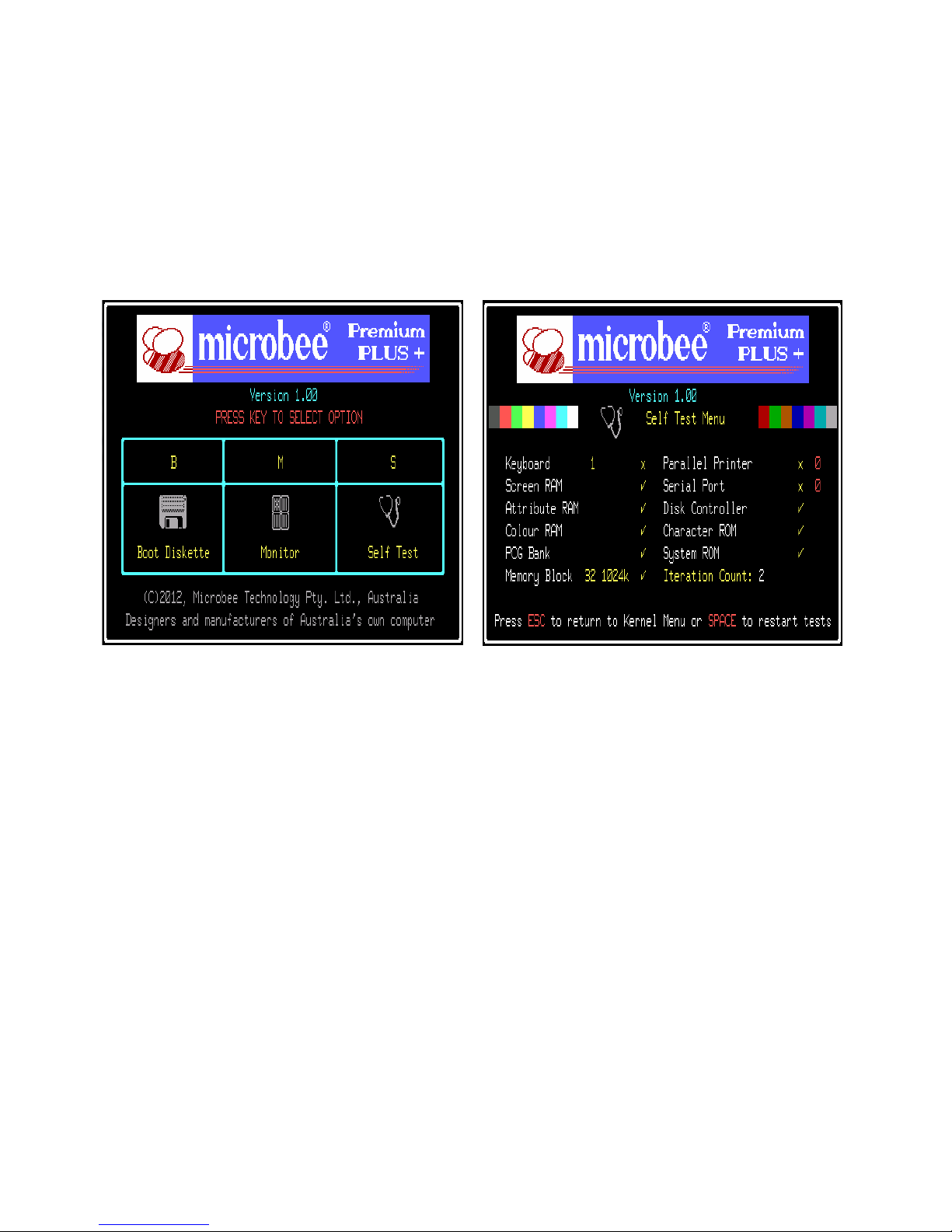
The 5 pin din lead that plugs into the Microbee has 4 plugs on the other end, or 3 & a plug
pack power supply. One of the other connectors on the cable is an RCA connector. This
connector provides monochrome video output and can be plugged into a suitable monitor or
a television that has an ‘AV’ input. Connect this to the monitor / TV now and have it
switched on and ready to display the boot screen of the Premium Plus.
Apply power now (from the Plug Pak or other suitable 10 – 14 Vdc 1.5amp power supply)
and if all is well, the RED L.E.D. on the coreboard should flash once & you should see the
boot menu on your monitor.
On the left (above) is the boot menu that appears when there is no SDcard in the socket at
boot time (and no disk in the disk drive if you have the physical floppy disk interface option
installed on the coreboard). The boot menu gives you 3 options – Boot disk, [machine
language] Monitor , and Self Test.
Press the ‘S’ key to activate the self test mode. It should look like the screen shot on the
right (don’t forget that you will only have monochrome video, so no color). The keyboard
test is the first item to run and for now just press ESC twice to bypass it. All items should
pass with the exception of the serial and parallel port tests which need specially wired
loopback plugs. The PCG Bank test should test all 15 banks of memory, and the Memory
Block test should test all 1024k of memory available to the ‘Z80 mode’ side of the Microbee.
If all is well and all the tests run through as they should, reset the machine by holding down
RESET for 1 second & enter Self test again. This time, run through the keyboard test.
The test asks you to press each key in turn starting with ESC,1,2,3… and works down the
keyboard in rows TAB,Q,W,E,R…, CTRL, LOCK, A,S and so on.
Once you are happy that all the self test diagnostics have passed, try re-booting the
machine with the SDcard in the slot.
To insert the SDcard, the card has to be upside-down. That is, the contacts on the card
should be facing upwards & the label on the card facing down. The SDcard connector is a
PUSH-PUSH type – that is, when the card is inserted, you push it all the way in & it locks
into place. When you want to remove the card again, you push the card inwards again to
Page 20 of 31. Version 1.03 September 2012 Microbee Premium Plus+ | Construction Manual
Page 21

unlock it & it springs out. You can insert the card while the self test is still running and then
hold down the reset key for 1 second (you should see the current test running freeze after a
second) and then release the reset key. The Premium Plus should then reset itself, the RED
L.E.D. should flash a number of times & after a few seconds the Microbee SHELL should
appear with the list of files on the ‘disk’. If you get this far, CONGRATULATIONS, you have
successfully built your very own Microbee Premium Plus!
The last thing to do of course is to put the casing together.
The baseboard is held into the bottom of the case with a screw & flat washer at either side
of the keyboard frame. The kit was shipped with these screws in place, holding the
keyboard frame. Lastly comes the fitting of the top case. The LEDs on the coreboard show
through the metal badge on the top of the rear top case. These may need aligning with the
slots in the badge and this can be done by bending the leads a little so that the natural
position lines up under the centre of each slot in the badge. Once this is done, the case can
be screwed together. There are six 3mm x 16mm screws that fit in the underside of the
case and screw into the top case sections.
Now your new Microbee Premium Plus is complete.
Enjoy!
Page 21 of 31. Version 1.03 September 2012 Microbee Premium Plus+ | Construction Manual
Page 22

10. Bill of materials / Parts list
Microbee Premium Plus Baseboard (8501-04) Bill of Materials
IC's
Manufacturers
Part# Description Component Ref ID's Qty
Z80PIO Z80 Parallel input/output chip - DIP40 IC9 1
74ALS574 Octal Latch DIP20 IC32, 36, 37, 38, 39 5
74LS541 Unidirectional Buffer 8 bit DIP20 IC40, 34, 41, 28 4
74LS00 Quad 2 input NAND gate DIP 14 IC47 1
74LS04 Hex inverting buffer DIP 14 IC55, 74, 67, 6 4
74HCT08 Quad 2 input AND gate HC DIP14 IC63 1
74LS32 Quad 2 input OR gate DIP14 IC72, 48, 58, 78, 24, 4 6
Z80CPU Z80 Central processor Unit IC33 1
74LS11 Triple 3 input AND gate DIP14 IC56 1
74LS161 BCD Decade counter DIP16 IC64 1
74LS74 Dual D flip-flop DIP14 IC73, 25, 49, 57 4
74LS10 Triple 3 input NAND gate IC65 1
74LS139 Dual 1of4 decoder DIP16 IC61 1
74LS645/245 Octal Buffer bi-directional DIP20 IC17, 26, 29, 30, 31 5
74HC32 Quad 2 input OR gate HC DIP14 IC66 1
7407/17 Hex buffer O/C DIP14 IC75 1
74LS273 Octal transparent Latch DIP20 IC27 1
74LS157 Quad 2-1 Mux DIP16 IC35, 43, 44, 45, 46, 11, 12, 13 8
74LS166 8 bit shift reg Parallel in Ser out DIP 16 IC42 1
FONTROM / 2532 Microbee Dual Font ROM IC50 1
74LS174 Hex D Latch DIP16 IC59 1
74LS86 Quad 2 input XOR gate IC69 1
74LS08 Quad 2 input AND gate DIP14 IC76, 68, 5 3
74LS573 Octal Latch DIP20 IC18 1
CY62256 32K x 8bit Static Ram IC51 1
CY7C128 2K x 8bit Static Ram IC19, 20, 21 3
GOLD_PAL Microbee Premium PAL IC62 1
74LS138 1of8 decoder DIP16 IC71 1
74LS175 Hex Latch DIP16 IC77 1
74LS156 3to8 encoder DIP16 IC7 1
74HC151 1of8 mux DIP16 IC3 1
CA3140 Op amp IC80 1
SY6545-1 CRT controller DIP 40 IC1 1
7805 5 v regulator TO-220 IC8, 79 2
Page 22 of 31. Version 1.03 September 2012 Microbee Premium Plus+ | Construction Manual
Page 23

Misc
Semiconductors
Manufacturers
Part# Description Component Ref ID's Qty
D23, 24, 3, 4, 5, 6, 16, 18, 20,
1N914/4148 1N914/4148 Small Signal Diode
21,22 11
BC548 BC548 Small Signal NPN transistor Q1, IC23 2
Passive
Components
Manufacturers
Part# Description Component Ref ID's Qty
100NBYPASS 100nF Bypass cap - through hole 61
2U2-25V-TANT 2.2uF or 4.7uF 25v or greater rating C12,80 2
4U7-16V-TANT 4u7 16v Tant cap C2,11,14,35,45,78,79 7
470uF 25v Electro 470uF 25v Electro C71 1
47PF-50V-CER 47pF 50v Ceramic Capacitor C84 1
10NBYPASS 10nF 50v Ceramic Capacitor C81 1
RSIP4K7X9 Resistor SIP 4K7 x 9 10 pin RN2,RN3 2
RSIP10K0X9 Resistor SIP 10K x 9 10 pin RN1 1
330R 1/4W 330R 1/4W resistor, TH R15,22,27,28 4
270R 1/4W 270R 1/4W resistor, TH R24 1
82R 1/4W 82R 1/4W resistor, TH R26,33 2
1K 1/4W 1K0 1/4W resistor, TH C18, R20,21,25,31,35,38 7
470R 1/4W 470R 1/4W resistor, TH R37 1
1K5 1/4W 1K5 1/4W resistor, TH R10,12,30,36 4
18K 1/4W 18K 1/4W resistor, TH R13 1
10K 1/4W 10K 1/4W resistor, TH R11,29,32 3
680R 1/4W 680R 1/4W resistor, TH R19 1
4K7 1/4W 4K7 1/W resistor, TH R6,9,34 3
13M5XTAL 13.5Mhz crystal HC49 G2 1
Connectors
Manufacturers
Part# Description Component Ref ID's Qty
DN09FR1A0N DB9 female R/A conn X1 1
DN15FR1A0N DB15 female R/A conn X3 1
DN25FR1A0N DB25 female R/A conn X5 1
5 pin R/A PCB MNT Female DIN X8 1
25 way pin strip socket Vert MNT X2, 7 2
2 way pin strip socket Vert MNT X6 (pins 13 & 14) 1
Page 23 of 31. Version 1.03 September 2012 Microbee Premium Plus+ | Construction Manual
Page 24

Hardware / Misc
Manufacturers
Part# Description Component Ref ID's Qty
8501-04 Premium Baseboard PCB 1
IC Socket 40 PIN DIP IC9, 33, 1 3
IC Socket 24 PIN 300mil (Skinny) DIP IC19, 20, 21, 62 4
IC Socket 24 PIN 600mil DIP IC50 1
Keyswitch Pushbutton 64
PremPlus keyboard Frame 1
PremPlus Keycap set 1
M3x6 bolts 2
M3 nut 2
Spring washers - M3 2
TO-220 heatsink thermal washer 2
M3 x 16mm bolt 6
S/tap screw - Speaker mount 2
Speaker clamp 2
rubber feet 4
microbee premium case badge 1
50ohm 50mm Speaker 1
Microbee premium case set 1
Premium Plus coreboard (assembled) 1
Page 24 of 31. Version 1.03 September 2012 Microbee Premium Plus+ | Construction Manual
Page 25
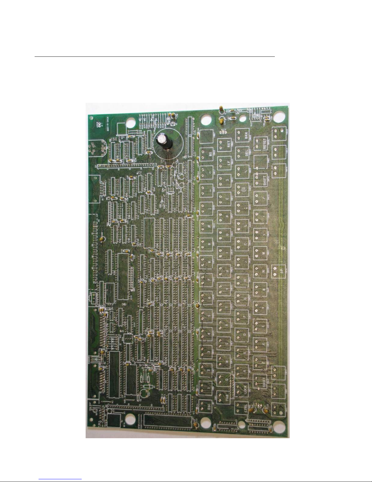
11. ‘Check photos’
This section contains photos of the Premium baseboard at various stages of assembly. They
have been included here as a reference for you that can be referred to and compared to
where you are at in your assembly of the kit.
Check Photo ‘1’ – capacitors installed.
Page 25 of 31. Version 1.03 September 2012 Microbee Premium Plus+ | Construction Manual
Page 26
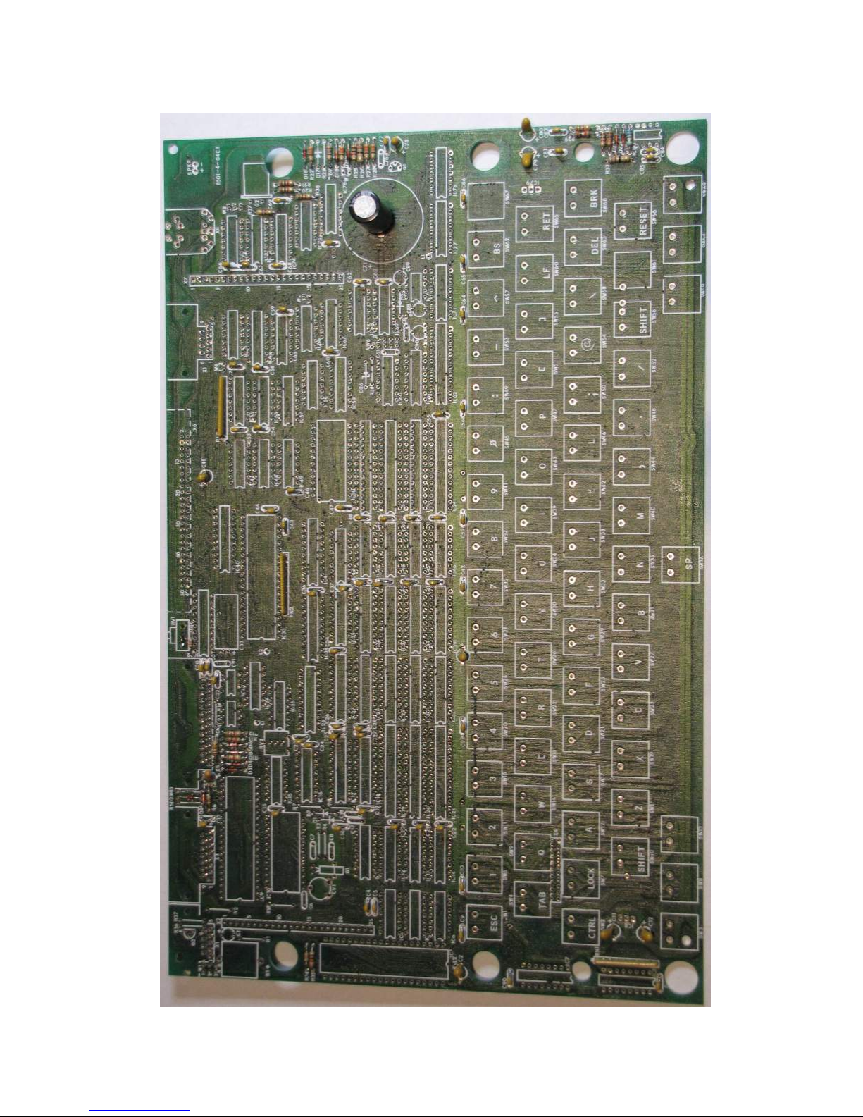
Check Photo ‘2’ – resistors installed.
Page 26 of 31. Version 1.03 September 2012 Microbee Premium Plus+ | Construction Manual
Page 27
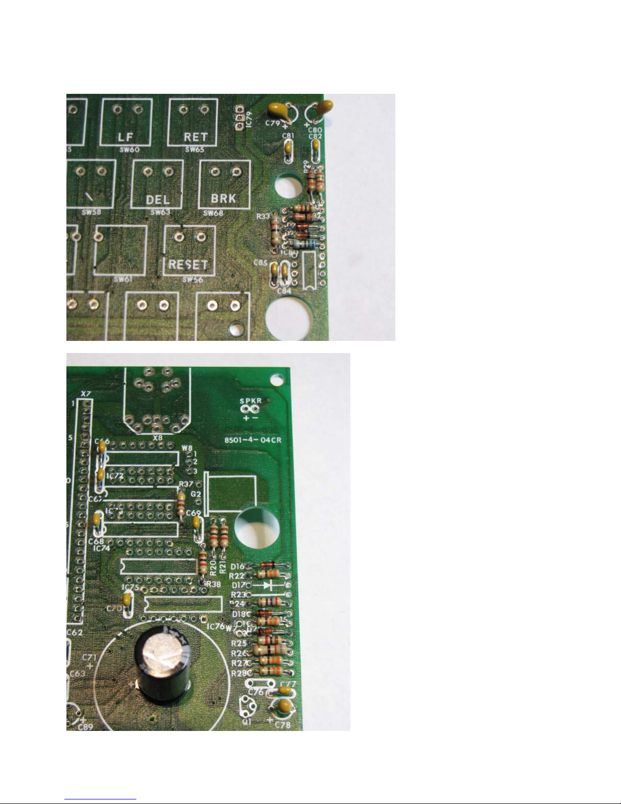
Check photo ‘3, 4 & 5’ – Close up of passive components
Page 27 of 31. Version 1.03 September 2012 Microbee Premium Plus+ | Construction Manual
Page 28
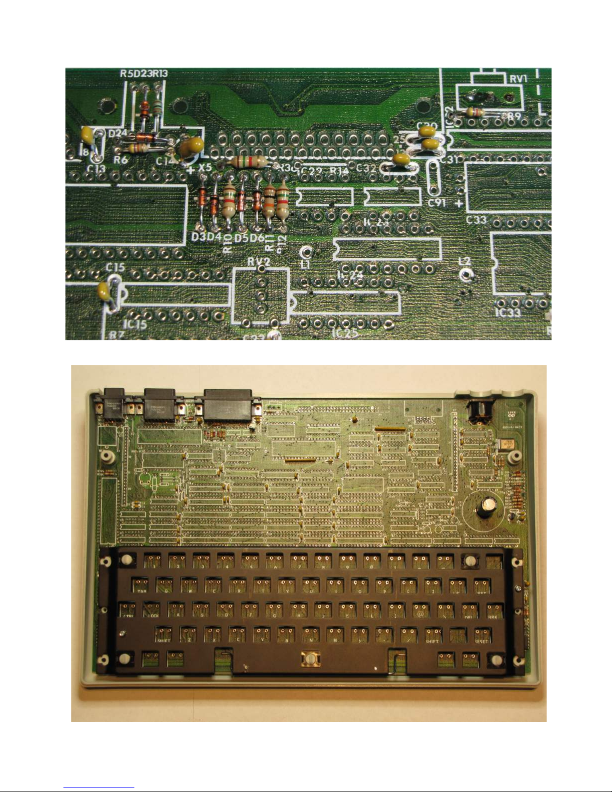
Check photo ‘6’ – Regulators installed with Keyboard frame
Page 28 of 31. Version 1.03 September 2012 Microbee Premium Plus+ | Construction Manual
Page 29
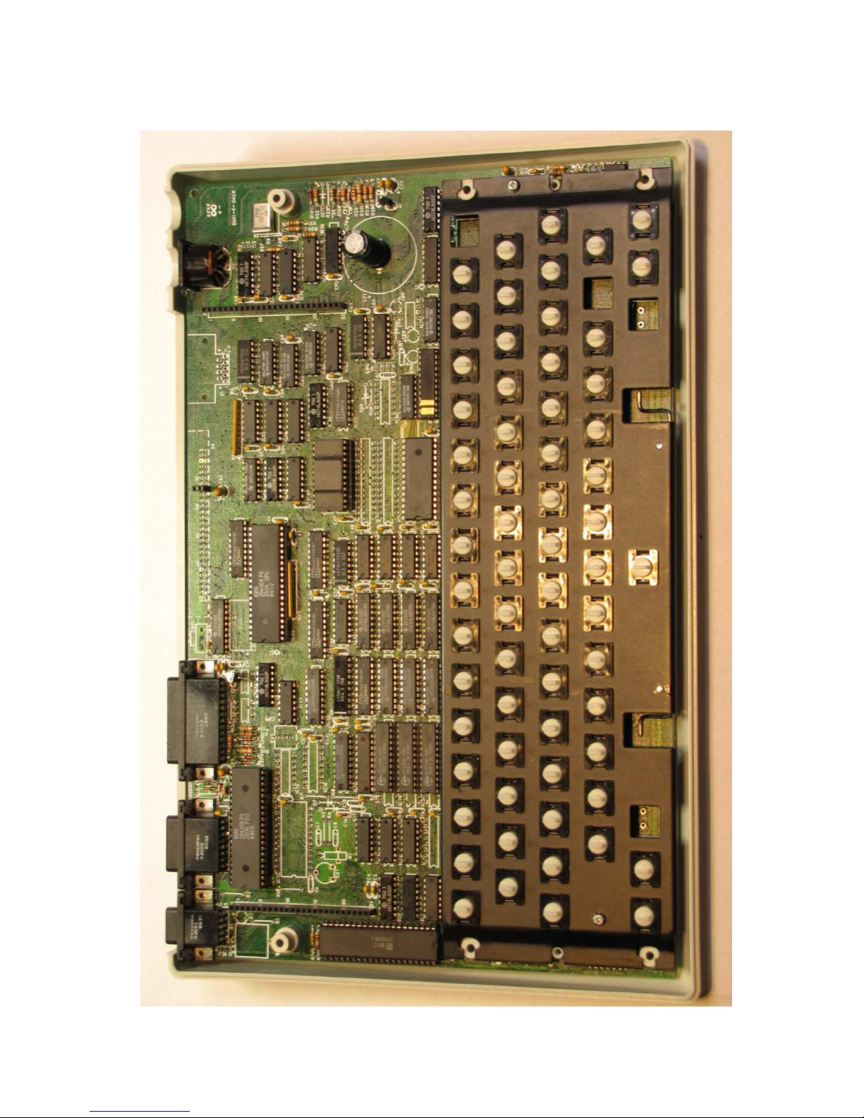
Check Photo ‘7’ – baseboard complete – no key tops installed.
Page 29 of 31. Version 1.03 September 2012 Microbee Premium Plus+ | Construction Manual
Page 30
Page 30 of 31. Version 1.03 September 2012 Microbee Premium Plus+ | Construction Manual
Page 31
Page 31 of 31. Version 1.03 September 2012 Microbee Premium Plus+ | Construction Manual
 Loading...