

Page 1

ES3
Pure Tone Audiometer
User’s Guide
Rev 1.11
Page 2

Precautionary Notes: Earscan® 3 Audiometer
1. Use only the factory-supplied, UL approved, power adapter (wall cube)
with the Earscan® 3. Use of any other power adapter will invalidate the
warranty and may result in damage to the audiometer.
2. The Earscan® 3 is designed for use with alkaline 1.5 volt AA size batteries.
If re-chargeable batteries are used, they must be of the alkaline type. Do not
use nickel-metal hydride (NiMH) or nickel cadmium (NiCad) rechargeable
batteries.
3. When installing batteries in the Earscan® 3, you must observe the correct
polarity. If one or more cells are installed with reversed polarity, the
instrument will not operate in the battery-powered mode, and the audiometer
may be damaged.
4. The Earscan® 3 is capable of producing signal levels greater than 100 dB
SPL. Prolonged exposure to signals at these levels can result in temporary
threshold shift or permanent hearing loss. When testing in manual mode at
high HTL settings, limit signal duration to no more than 1 second.
5. If the Earscan® 3 has only external power available (low batteries or no
batteries installed), be aware that unplugging the mini DIN connector will
result in power loss and potential data loss. If it is necessary to disconnect
the mini DIN in this case (e.g., to switch from USB cable to printer cable), it is
advisable to turn the instrument off, make the cable change, then turn the
instrument back on.
6. The Earscan® 3 does not implement handshaking protocol on the serial
port. This means that the ES3 will not detect an unconnected serial port or a
‘printer not ready’ condition.
7. Data stored on Earscan® 3 SD flash memory cards should be backed up to
a PC on a regular basis to avoid potential data loss.
®
Earscan
E·A·R
Microsoft
Information in this manual is believed to be accurate; however, Micro Audiometrics
Corporation assumes no responsibility for its use. Content is subject to change
without notice. No part of this manual may be reproduced without written permission.
Copyright © 2004-2007 Micro Audiometrics Corporation. PN: 95.707.111
is a registered trademark of Micro Audiometrics Corporation.
®
and E·A·RTONE® are registered trademarks of Aearo Company.
®
and Windows® are registered trademarks of Microsoft Corporation.
2
Page 3

Table of Contents
Introduction .........................................................................................................6
Manual Conventions ....................................................................................... 6
Keypad ........................................................................................................... 7
Menu Navigation............................................................................................. 7
Function Keys................................................................................................. 8
Setup ....................................................................................................................9
Cable Connections ......................................................................................... 9
Power Up........................................................................................................ 9
Power Options .............................................................................................. 10
Beep Volumes .............................................................................................. 10
Talk Over ...................................................................................................... 11
Time and Date .............................................................................................. 11
Manual Audiometry...........................................................................................12
Manual Audiometry Key Functions ............................................................... 13
Testing Procedure ........................................................................................ 14
Manual Audiometry Options ......................................................................... 14
Frequency Selection ............................................................................... 14
Other Options.......................................................................................... 15
Automatic Threshold Audiometry....................................................................16
Automatic Threshold Function Key ............................................................... 16
Test Procedure ............................................................................................. 17
Test Protocol ................................................................................................ 17
Automatic Threshold Test Error Conditions .................................................. 18
Automatic Threshold Audiometry Options .................................................... 18
Frequency Selection ............................................................................... 18
Frequency Presentation Order................................................................ 18
Other Options.......................................................................................... 19
Subject Demographics .....................................................................................20
Test Results.......................................................................................................21
Displaying Results on the LCD ..................................................................... 21
Display Results Key Functions................................................................ 22
Quantifying Hearing Loss ............................................................................. 22
3
Page 4

Data Storage ......................................................................................................22
Saving Tests................................................................................................. 23
Loading Tests ............................................................................................... 23
Marking Baseline Test .................................................................................. 24
Serial Communications ....................................................................................24
Transmit Options .......................................................................................... 24
Baseline Comparisons......................................................................................25
Screen and Clock Options................................................................................25
Screen Properties ......................................................................................... 25
Power-Up Logo....................................................................................... 26
Real-Time Clock Settings ............................................................................. 26
Lock Settings.....................................................................................................27
Reset Settings ...................................................................................................27
Firmware Upgrade.............................................................................................27
Headset Management .......................................................................................28
Calibration .........................................................................................................29
Technical Specifications ..................................................................................30
Functional ‘Quick Checks’ ...............................................................................31
Trouble Shooting Guide ...................................................................................32
External Interface ..............................................................................................33
Connectors ................................................................................................... 33
Multi-purpose Connector......................................................................... 33
Headset Connector................................................................................. 34
DPU-414 Printer Switch Settings ............................................................ 34
Earscan 3 Information.......................................................................................35
Warranty.............................................................................................................36
Contact Information ..........................................................................................37
4
Page 5

List of Tables
TABLE 1. POWER SETTINGS.................................................................................. 10
TABLE 2. MANUAL AUDIOMETRY KEY FUNCTIONS................................................... 13
TABLE 3. OTHER MANUAL AUDIOMETRY OPTIONS .................................................. 15
TABLE 4. AUTOMATIC THRESHOLD AUDIOMETRY ERRORS ....................................... 18
TABLE 5. BASIC AUTOMATIC THRESHOLD TEST OPTIONS ........................................ 19
TABLE 6. ADVANCED AUTOMATIC THRESHOLD TEST OPTIONS ................................. 20
TABLE 7. SUBJECT DEMOGRAPHIC INFORMATION ................................................... 20
TABLE 8. DISPLAY RESULTS KEY FUNCTIONS......................................................... 22
TABLE 9. SCALE OF HEARING LOSS....................................................................... 22
TABLE 10. DATA TRANSMIT OPTIONS .................................................................... 24
List of Figures
FIGURE 1. ES3 KEYPAD ......................................................................................... 7
FIGURE 2. MAPPING FUNCTION KEYS TO LCD TEXT.................................................. 8
FIGURE 3. MANUAL AUDIOMETRY DISPLAY............................................................. 12
FIGURE 4. DISPLAY OF THRESHOLD ....................................................................... 13
FIGURE 5. AUTOMATIC THRESHOLD DISPLAY.......................................................... 16
FIGURE 6. AUDIOMETRIC TEST RESULTS DISPLAY................................................... 21
FIGURE 7. INFORMATION DISPLAY.......................................................................... 35
5
Page 6

INTRODUCTION
The Earscan 3 model ES3 is a pure tone, full frequency, air conduction
audiometers. It provides manual/automatic threshold test capability with talk over.
The ES3 is optimized for use in hearing conservation programs. It can be PCcontrolled and optional provides data storage capability (via removable SD flash
memory card), baseline comparisons and STS/PBI calculations.
ES3 audiometers are user customizable, can be battery or AC powered, and offer
flexibility in communications. One of the most powerful ES3 features is the ability to
be updated or upgraded via a PC attached to the Internet. Using factory supplied
software, firmware updates/upgrades can be downloaded from the Micro
Audiometrics website and installed on the ES3. Micro Audiometrics will be
periodically adding new features to the ES3 firmware, and these features can be
downloaded from the Micro Audiometrics website or obtained from an authorized
Micro Audiometrics distributor.
Manual Conventions
The following conventions are used to indicate interactions with ES3:
KEY Presses appear in { }; e.g. {▲} means press the ▲ key.
Basic menu navigation is done using {▲} / {▼} and {◄} / {►}.
Use the {Ο} key to present tones, select menu items, or select list items.
It’s the navigation key in the center of the array:
▲
◄ Ο ►
▼
Menu sequences appear as ⌐M
indicate “scroll to Menu Item and press the Ο key, or press the number key
corresponding to the Menu Item”.
ENU1 ⌐MENU2 ⌐MENU3. The “⌐” symbol is used to
6
Page 7
Keypad
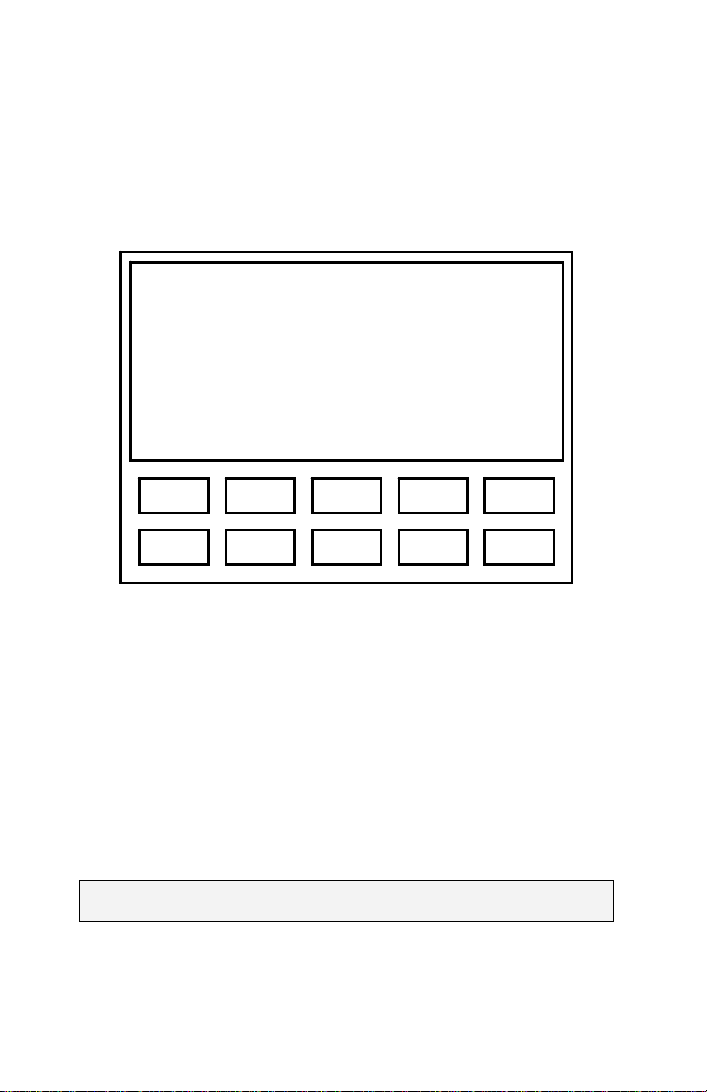
ES3 audiometers have a blue keypad/overlay with 10 keys, labeled 1 through 0
(see Figure 1).
Figure 1. ES3 Keypad
10 labeled keys
1 through 0
3 1 5 2 4
8 6 0 7 9
Menu Navigation
The ES3 menu system is designed for intuitive use. Navigating through menus is
as simple as using the {▲}, {▼}, {►}, or {◄} keys to highlight a selection and then
pressing {Ο} to make a selection. The {Menu} key is used to exit test mode and
enter the menu system, and also to move from ‘lower’ to ‘higher’ menu screens.
Pressing {Menu} while in manual audiometry mode enters the ‘top level’ of the
menu system, and if the user has navigated ‘down’ into the menu structure, each
{Menu} press will return to the next ‘higher’ menu level until the ‘top level’ menu is
reached. Menu sequences are shown assuming that the user begins at the ‘top
level’ menu.
Note: The ‘top level’ menu can always be reached by repeatedly
pressing {Menu}.
7
Page 8
Function Keys
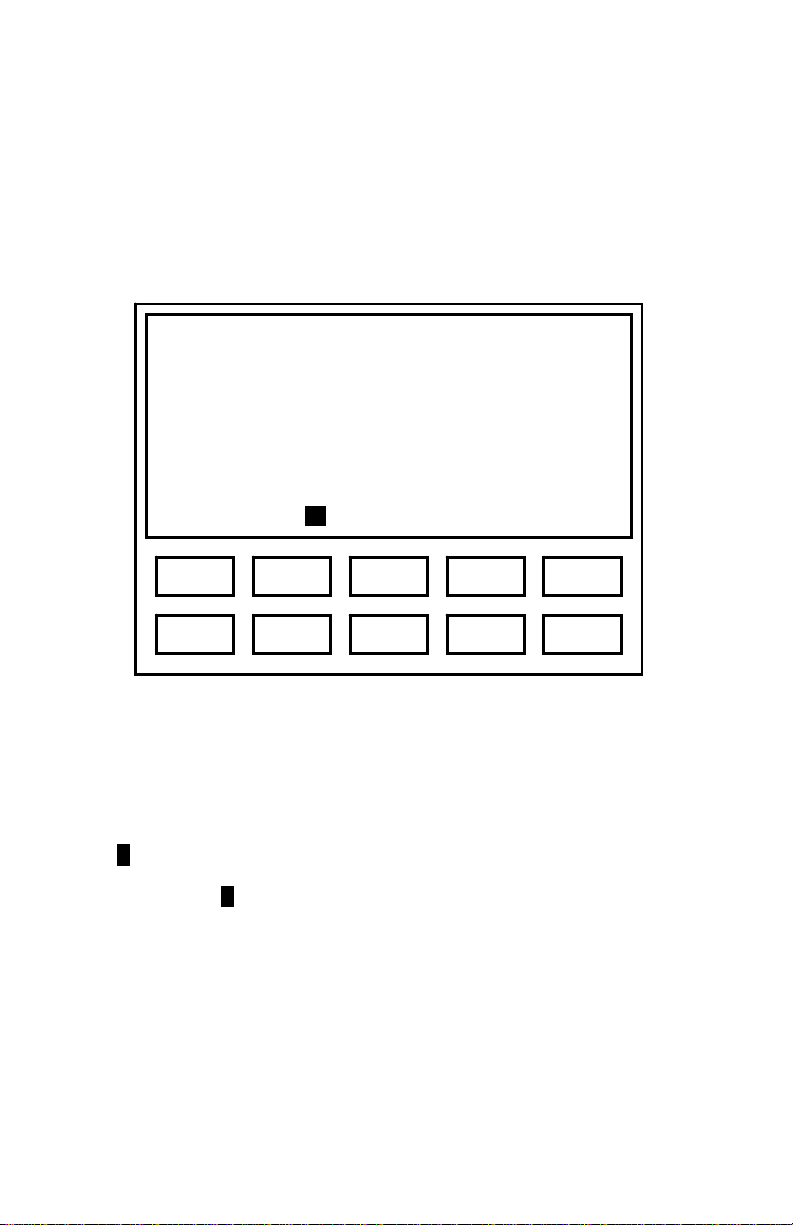
At times, ‘actions’ or ‘toggles’ will be displayed on the bottom line of the LCD. The
keys just below the display are then used as ‘function’ keys to perform an action
(A), or to toggle between two possible parameter values (a/b).
Figure 2 illustrates how keys are mapped to actions or toggles shown on the LCD.
Figure 2. Mapping Function Keys to LCD Text
Upper screen area
displays text.
Last line may display
text OR function key
assignment; e.g.,
Auto L/R Send Clr Talk
3 1 5 2 4
8 6 0 7 9
In this illustrative example, there are four ‘Actions’ (Auto, Send, Clr, and Talk)
assigned to ‘Function’ keys 1, 3, 4, and 5. Press {1} to perform action Auto, {3} to
perform the action Send, {4} to perform action Clr, and {5} to perform action Talk.
The ‘L/R’ shown above {2} indicates an L/R toggle with ‘R’ currently selected.
Pressing {2} will toggle between the two possible states, and the state selected will
be highlighted (e.g., R).
8
Page 9

SETUP
Cable Connections
ES3 audiometers can be powered by 4 AA Alkaline batteries (battery compartment
is accessible from the back of the instrument). Optionally, power from an AC
adapter or USB bus power can be supplied via the 6-pin multi-purpose “mini DIN”
connector on the top of the instrument. The AC adapter may be plugged directly
into the ES3 mini DIN socket if serial communication is not required, or it may be
plugged into the power adapter receptacle at the end of a printer cable or optional
computer interface cable (RS-232). The headset and response button cable
assembly plugs into the 15-pin connector on the top of the instrument.
Booth wall and headphone adapter cables are provided for installations that
require patching through a booth. The booth adapter cable replaces the ES3
headphone/response button cable and terminates in three ¼” phone plugs
compatible with standard booth patch panels. The headphone adapter cable
provides ¼” mono phone plugs for TDH-39 headphones.
Power Up
Press the {On} key, and the ES3 logo will scroll onto the screen unless scrolling
has been disabled (see Power Up Logo
due to an inactivity time-out. When power-up initialization is completed, enter {1}
to begin a new test or enter {2} to continue a previous test automatically saved by
the ES3 at its last power down.
If you choose to begin a new test, the ES3 will prompt you to enter the Patient ID
and an Operator ID. If the Test Analysis option is installed, it will also check to see
if baseline data is available. If baseline data is found, you will be given the option
to load the data. You will then be prompted to enter patient’s gender, age, number
of hours since last noise exposure, and an Operator ID.
The manual audiometry screen will then be displayed and the instrument is ready
to begin testing.
Note: When the ES3 powers down due to an inactivity timeout or in response to
URN OFF, current test data is automatically saved to non-volatile memory. This
⌐T
prevents loss of data in case a test is interrupted. When the ES3S is powered
back on, pending test data will be restored and the test can be continued, if
desired, or a new test can be started.
), or the instrument was last powered down
9
Page 10

Power Options
Inactivity timeouts automatically turn off the LCD backlight and power after
selectable periods of inactivity to conserve energy and extend battery life (see
Table 1; ( ) indicates default setting).
Note: The backlight requires considerable battery power. Setting the backlight
power-down interval longer than necessary will decrease battery life when the ES3
is battery powered (see Screen Properties
Table 1. Power Settings
AC
Backlight
⌐S
ETUP ⌐POWER ⌐A/C ⌐BACKLIGHT
AC
Power Down
⌐SETUP ⌐POWER ⌐A/C ⌐POWER DOWN
Battery
Backlight
ETUP ⌐POWER ⌐BATTERY ⌐BACKLIGHT
⌐S
Battery
Power Down
⌐SETUP ⌐POWER ⌐BATTERY ⌐POWER DOWN
).
(Never)
30 seconds
1 minute
2 minutes
5 minutes
Never
1 minute
5 minutes
(15 minutes)
30 minutes
1 hour
5 seconds
10 seconds
(20 seconds)
30 seconds
1 minute
15 seconds
30 seconds
(1 minute)
2 minutes
5 minutes
Beep Volumes
Key presses are silent when in test mode, but produce audible ‘beeps’ when in the
menu system. The beep volume can be set via the menu sequence ⌐S
ETUP ⌐BEEP
VOLUMES ⌐KEY VOLUME {Low/Medium/High}. The ES3 also produces an alert
sound when certain errors occur and to indicate the completion of an automatic
test. The volume of the alert can be set via the menu sequence ⌐SETUP ⌐BEEP
VOLUMES ⌐ALERT VOLUME {Low/Medium/High}.
10
Page 11

Talk Over
Talk over mode may be entered by pressing {5} while in audiometric testing mode.
There is no specific microphone ‘opening’; sound arrives at the microphone
through various openings in the cabinet (e.g., the slot in the side). Talk over
volume may be adjusted with the {▲}, {▼}, {►}, or {◄} keys. It is recommended
that a normal speaking voice be used at a distance of 1 to 2 feet, and volume
adjustment used to compensate for hearing status of the listener. Press {1},
{Menu}, or {Ο} to exit talk over.
Time and Date
The ES3 has a battery-backed up real time clock to maintain time and date. The
clock is set at the factory prior to shipment. See section Real-Time Clock Settings
for details on how to check or set the time and date. The backup battery is a
lithium rechargeable type and will be recharged whenever ES3 power is on.
Note: If the ES3 is not powered up for many months, the battery may become
discharged. In this case, the time and date will need to be reset and the instrument
should be left powered up for some time to recharge the clock battery. Normal
instrument usage is sufficient to keep the battery fully charged.
11
Page 12
MANUAL AUDIOMETRY
To insure that pending data is cleared, always begin a new test via the main menu
sequence ⌐NEW TEST to clear pending test data.
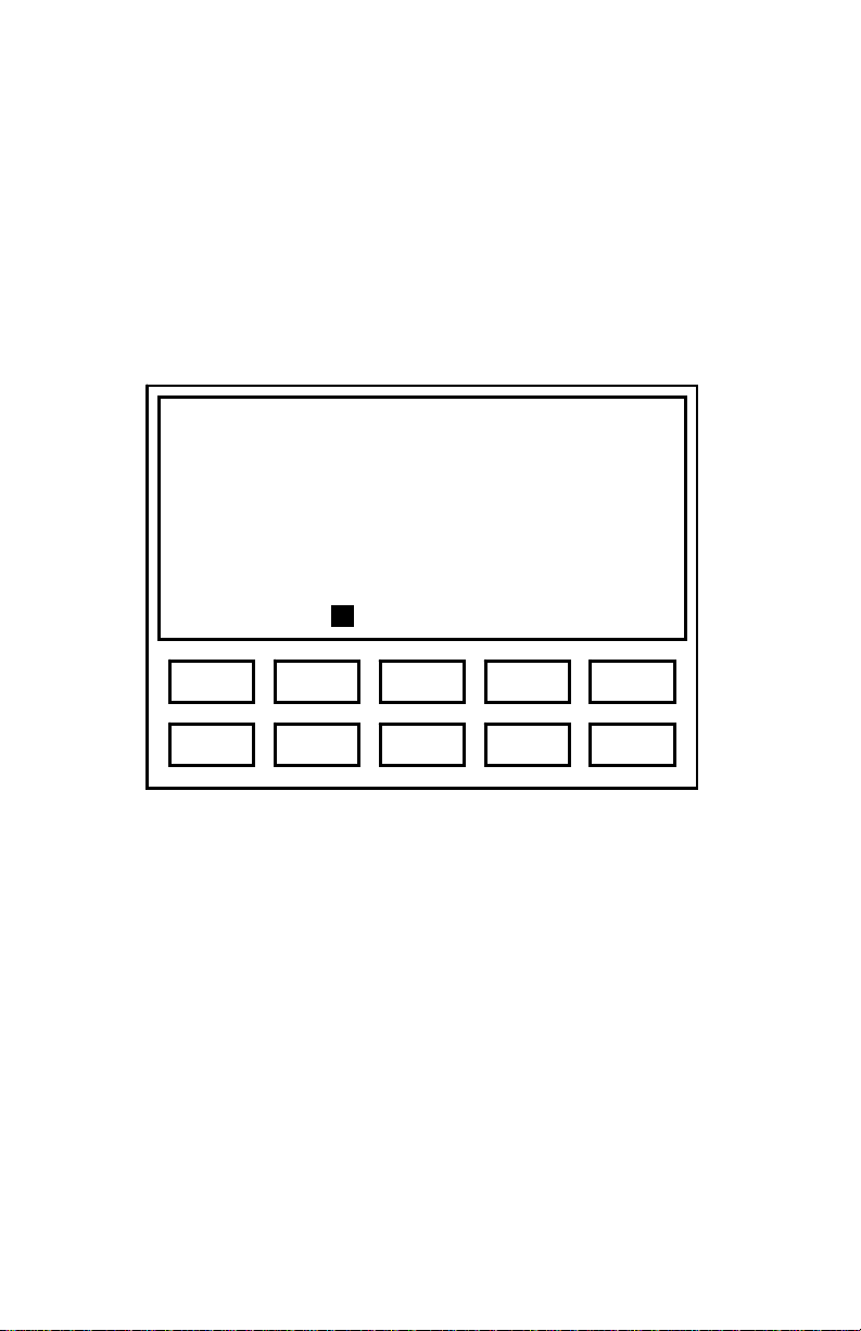
When the ES3 enters manual audiometry mode, the screen format shown in
Figure 3 will be displayed (assumes factory defaults for starting frequency and
level).
Figure 3. Manual Audiometry Display
Frequency 1000 Hz
Level 20 dB
Ear Right
Untested
Auto L/R Send Clr Talk
3 1 5 2 4
8 6 0 7 9
Once a threshold has been obtained, the display will change to show the threshold
value (the ‘m’ indicates threshold was obtained via manual testing; see Figure 4).
12
Page 13
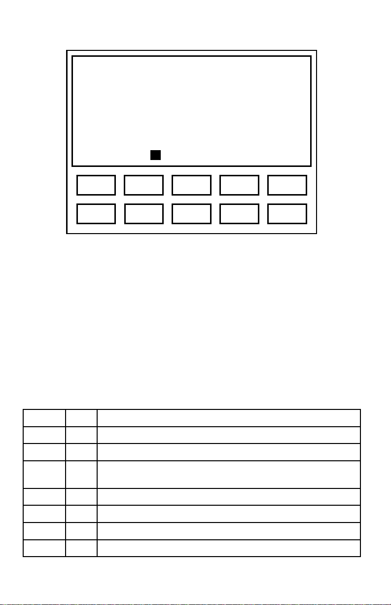
Figure 4. Display of Threshold
Frequency 1000 Hz
Level 20m dB
Ear Right
Auto L/R Send Clr Talk
3 1 5 2 4
8 6 0 7 9
The threshold may be cleared (Clr) by pressing key {4} (e.g., to retest a threshold).
Only the currently-displayed threshold will be cleared.
The test ear, signal mode, starting frequency and starting level are all user
selectable, so these values may differ from the ones shown. The example shown
indicates that threshold of 20 dB has been obtained for the right ear at 1000 Hz.
Manual Audiometry Key Functions
Table 2 lists the functions of ES3 keys that are active in the manual audiometry
mode. The last column indicates the action of the function keys.
Table 2. Manual Audiometry Key Functions
{◄}/{►} Select next lower/higher enabled frequency (Hz)
{▲}/{▼} Increase/decrease level by current step size (dB)
{1}
{2}
{3}
{4}
{5}
{Menu}
Auto Exit manual test mode and enter automatic test mode
L/R Toggle between Left and Right ear, or among Left, Right and
Binaural if binaural testing is enabled
Send Send the test data to computer or printer
Clr Clear the current threshold
Talk Exit test mode and enters talk over mode
Exits manual test mode and enters the menu system
13
Page 14

Testing Procedure
1) Instruct the patient to raise his/her hand or press the patient response button
(if available) whenever a tone is heard.
2) Position the headphones over the patient’s ears (Red over Right ear, Blue
over Left ear).
3) Press {2} if necessary to toggle to the desired test ear.
4) Select the test frequency using the {◄} / {►} keys.
5) Use the {▲} / {▼} keys to adjust the hearing level and the {Ο} key to
present the stimulus to the selected ear. When testing with Continuous
signals, stimulus duration should be about 1 second; the minimum
duration allowed is 200 ms.
6) Continue using the {▲} / {▼} and {Ο} to present stimuli consistent with the
test paradigm being used (typically Hughson-Westlake) until threshold is
determined.
7) Use the {◄} / {►} keys to select the next frequency to test.
8) Repeat steps 4 through 7 until threshold has been determined for each
frequency for the selected ear.
9) Change the test Ear by pressing {2}.
10) Repeat steps 4 through 8 until threshold has been determined for each
frequency for the second ear.
Manual Audiometry Options
Frequency Selection
Note that the set of test frequencies selected for manual audiometry will also be
used during automatic threshold testing. By default the frequency set includes
250, 500, 1000, 2000, 3000, 4000, 6000, and 8000 Hz, plus the 1k/Validity check.
The 1k/Validity check is mainly used during an automatic threshold exam, but can
also be tested during a manual exam if desired.
The frequency set to be used for manual or automatic threshold testing may be
viewed or modified via the menu sequence ⌐S
⌐FREQUENCIES. The display will show the list of available test frequencies and
there will be a check mark (√) next to the ones currently selected for testing. Use
the {►}, {▲}, {▼} and {◄} keys to move the highlight to a frequency to select or
deselect for testing, and press {Ο} to toggle between ‘selected’ and ‘deselected’.
Repeat this process as necessary to select or deselect other frequencies.
Once selections are completed, press {Menu} to exit frequency selection mode
and return to the menu system.
14
ETUP ⌐AUDIOMETRY SETUP
Page 15

Other Options
Additional manual audiometry options listed in Table 3 may be accessed via the
menu sequence ⌐S
ETUP ⌐AUDIOMETRY SETUP ⌐MANUAL AUDIOMETRY. To change an
option, highlight the option to modify using the {►}, {▲}, {▼} and {◄} keys, and
press {Ο}. Use the {►}, {▲}, {▼} and {◄} keys to select the desired setting for
the option, and press {Ο}.
Table 3. Other Manual Audiometry Options
Ear Ear to be tested first. Left, (Right)
Starting Level
Starting
Frequency
Tone Mode Stimulus mode (Pulsed), Continuous
Increment
Amount
Decrement
Amount
Binaural
Stimulus
Initial level when new test is
started
Initial frequency when
entering manual test mode
10, 15, (20), 25, 30, 35, 40
125, 250, 500, (1000), 1500,
2000, 3000, 4000, 6000, 8000,
1k/V
Increment step size (5), 10, 20
Decrement step size 5, (10), 20
Enable presentation to both
ears simultaneously
(No), Yes
15
Page 16
AUTOMATIC THRESHOLD AUDIOMETRY
To insure that pending data is cleared, always begin a new test via the main menu
sequence ⌐NEW TEST to clear pending test data.
The automatic threshold test option performs a modified Hughson-Westlake test.
Figure 5 shows the display format used for Automatic Threshold tests. This
example indicates that a threshold of 25 dB was registered in automatic test mode
(indicated by “a”) for 3000 Hz at the left ear.
Figure 5. Automatic Threshold Display
Frequency 3000 Hz
Level 25a dB
Ear Left
Man
3 1 5 2 4
8 6 0 7 9
Automatic Threshold Function Key
Pressing {1} (Man) during an automatic threshold exam will stop the test and return
the ES3 to the manual audiometry mode. Note that exiting the test does not clear
test data. The test may be re-entered and continued from the point at which it was
interrupted.
16
Page 17

Test Procedure
1) Instruct the patient to press the response button whenever a tone is heard.
2) Position the headphones over the patient’s ears.
3) From the manual audiometry screen, press key {1} to begin the automatic
threshold exam.
Test Protocol
1) The automatic test begins at the level and frequency indicated in the
automatic threshold audiometry settings.
If the Faster Method setting is selected:
The stimulus increment size is set to the Gross Increment size in the
automatic threshold audiometry settings. The increment size remains at
this setting until the first response by the patient to a stimulus. After the
first response, the increment step size is set to the Increment Amount in
the automatic threshold settings. The stimulus decrement size is set to
the Gross Decrement size in the automatic threshold audiometry
settings. The decrement size will remain at this setting until the first
negative response by the patient to a stimulus. After the first negative
response, the decrement size is set to the Decrement Amount in the
automatic threshold settings.
If the Faster Method setting is not selected:
The stimulus increment size is set to the Increment Amount and the
decrement size is set to the Decrement Amount in the automatic
threshold settings.
2) After each stimulus presentation, ES3 will either decrease the intensity
level by the decrement size if the patient responded or increment the
intensity level by the increment size if the patient did not respond.
3) The number of consecutive ascending positive responses at a given level
is selectable in the automatic threshold audiometry settings. An ascending
positive response is a positive response to a stimulus presentation that
immediately follows a negative response to the previous stimulus
presentation.
4) If the stimulus is presented at the maximum level for a given frequency and
a negative response is received by the ES3, the threshold for the
frequency is set to a No Response (NR) and the test continues with the
next frequency selected for testing.
5) Testing for the next frequency in the test sequence will automatically start
at an intensity level 10 dB HTL greater than the threshold for the previous
frequency. However, the test level will not exceed the maximum starting
level contained in the Level Override setting in the automatic threshold
audiometry settings. Additionally, if both the test storage and baseline
comparison upgrades are installed, the Use Baseline setting specifies that
testing will begin at the threshold for the baseline test if one exists and is
loaded.
17
Page 18

6) After testing at all the selected frequencies for the ear, the ES3 will
examine the other ear to see if testing has been completed for each
frequency. If the opposite ear has not been tested, ES3 will select the
opposite ear, and begin testing in the manner described beginning with
step 1. If both ears have been tested, the test is complete and ES3 will
return to the manual audiometry mode.
Automatic Threshold Test Error Conditions
If an error is encountered during an automatic threshold test, the ES3 will stop the
test and indicate the error condition. The operator may re-instruct the patient via
talk over mode and resume testing, or return to manual audiometry mode. Table 4
lists the error conditions that the ES3 detects.
Table 4. Automatic Threshold Audiometry Errors
Button Held Patient is holding down response button.
False Response
Inconsistent
Results
Validity Error The 1k and 1k/V thresholds differ by more than 5 dB.
Patient pressed response button outside the valid response
“window” or when no tone was presented.
A valid threshold was not obtained. Testing stopped at the
point where the error occurred.
Automatic Threshold Audiometry Options
Frequency Selection
Frequencies used during automatic threshold testing are the same as those for a
manual test (see Selecting Frequencies).
Frequency Presentation Order
Frequency presentation order may be changed via the menu sequence ⌐S
⌐AUDIOMETRY SETUP ⌐AUTO THRESHOLD ⌐FREQUENCY ORDER. The default sequence
is 1k/V, 500, 1000, 2000, 3000, 4000, 6000, and 8000 Hz. Only those frequencies
selected for testing will be used.
To change presentation order, move the highlight with the {◄} / {►} or {▲} / {▼}
keys and press {Ο} to select a frequency. Move it to any position in the list using
the {◄} / {►} or {▲} / {▼} keys, and press the {Ο} key to place it at that position.
When all frequencies are in the desired presentation order, press {Menu} to exit.
18
ETUP
Page 19

Other Options
Basic automatic threshold test options (see Table 5) are selectable via the menu
sequence ⌐S
ETUP ⌐AUDIOMETRY SETUP ⌐AUTO THRESHOLD.
Table 5. Basic Automatic Threshold Test Options
Ear
Frequency
Order
Starting Level
Increment
Amount
Decrement
Amount
Gross
Increment
Gross
Decrement
Advanced automatic threshold test options (see Table 6) are selectable via the
menu sequence ⌐S
Starting ear for automatic
threshold exam
Frequency presentation order
Starting level for automatic
threshold test
Left, (Right), Better Ear
1k/V, 500, 1000, 2000,
3000, 4000, 6000, 8000,
10, 15, 20, 25, (30), 35, 40
Level increment size (5), 10, 20, 30
Level decrement size 5, (10), 20, 30
Increment step size to use until
positive response has been
5, 10, (20), 30
registered
Decrement step size to use until
negative response has been
5, 10, (20), 30
registered
ETUP ⌐AUDIOMETRY SETUP ⌐AUTO THRESHOLD ⌐MISCELLANEOUS.
19
Page 20

Table 6. Advanced Automatic Threshold Test Options
Level Override
Faster Method
Stop On Inc.
Max Presentations
Use Baseline (requires
test storage & baseline
upgrades)
1k/V Test Both Ears
Max False Responses
Ascending Responses
Req
Maximum starting level when
changing frequency during
automatic threshold exam.
Should gross increments and
decrements be used?
Should test be stopped if a
reliable threshold cannot be
determined?
Maximum stimuli allowed per
frequency before reporting
‘inconsistent’ error.
Should baseline thresholds be
used to determine initial test
level?
Should 1k/Validity be tested for
both ears?
Maximum ‘false responses’
allowed before reporting an
error.
Number of consecutive
ascending responses required
to determine threshold.
40, 45, 50, 55, 60,
(65), 70
No, (Yes)
No, (Yes)
15, (20), 25, 30,
35, 40
No, (Yes)
No, (Yes)
1, 2, 3, 4, (5), 10
1, (2), 3, 4, 5
SUBJECT DEMOGRAPHICS
Subject demographic information can be stored along with threshold information on
the ES3 with the Test Storage upgrade. Demographic information can be entered
at any time via the menu sequence ⌐D
demographic information will appear when starting a new test.
Table 7 lists the demographic information that is stored. Numeric demographic
information is entered via the number keys. Gender is entered using the scroll
keys.
Table 7. Subject Demographic Information
Patient ID Up to 21 digits
Age 1 to 99
Gender Male or Female
Last Noise Exposure Hours since significant noise exposure: 1 to 99
Operator ID Up to 21 digits
EMOGRAPHIC INFO, and automatic prompts for
20
Page 21
TEST RESULTS
Audiometric test results can be displayed on the LCD, stored to a memory card or
transmitted to an attached PC or printer.
Displaying Results on the LCD
Test results are displayed via the menu sequence ⌐DISPLAY RESULTS. Thresholds
obtained via automatic testing are displayed with an ‘a’, and screening levels
obtained via automatic testing are displayed with an ‘s’. Figure 6 shows partial
results obtained in manual test mode for the Right ear (indicated by the ‘m’ next to
the threshold).
The {◄}, {►}, {▲}, or {▼} keys are used to scroll up or down through the results
list. Press {2} (L/R) to toggle between display of Left or Right ear data,
respectively. When baseline data is available (ES3 with Test Analysis option), it is
displayed in a column under the ‘Base’ heading. In this example, STS and PBI
calculations are available, so {4} would display STS calculations and {5} would
display PBI calculations. The formulae used for PBI calculations is selected via
ETUP ⌐AUDIOMETRY SETUP ⌐IMPAIRMENT CALC. {AAO-1979 / AAO-1965/AMA-
⌐S
1947 / NIOSH / CHABA / Illinois / New Jersey / Wisconsin}.
Figure 6. Audiometric Test Results Display
Right Results
Cur Base
125 20m
250 20m
500 20m
750 20m
1000 20m ↓
L/R STS PBI
1 5 2 4
3
8 6 0 7 9
21
Page 22

Display Results Key Functions
Table 8 lists the valid keys when in the display test results mode.
Table 8. Display Results Key Functions
{2} Toggle between left and right ear test results
{4}
{5} Display PBI using selected formula (Baseline upgrade)
{◄}, {►}
{▲}, {▼}
{Menu} Exit display mode and return to the menu system
Display STS and STS with Presbycusis results (Baseline
upgrade)
Scroll the display screen
Quantifying Hearing Loss
Table 9 provides a general reference for converting threshold in decibels to degree
of hearing loss.
Table 9. Scale of Hearing Loss
0 – 20 dB
25 – 40 dB
45 – 55 dB
60 – 70 dB
75 – 90 dB
90 dB+
Hearing within normal limits
Slight to mild hearing loss
Moderate hearing loss
Moderately severe hearing loss
Severe hearing loss
Profound hearing loss
DATA STORAGE
The ES3 with the Test Storage option can store audiometric test results on a
standard, removable, SD flash memory card. Utilizing widely adopted flash
storage cards facilitates transfer of test results between a PC database
management system and the ES3.
22
Page 23

Caution: It is important to make frequent backups of data to the PC to avoid
potential loss of data (e.g., if a card is lost or damaged).
The memory card must be formatted with the FAT16 file system. Most memory
cards come preformatted with FAT16, and this format can also be specified when
formatting a card, e.g., using Microsoft® Windows® and a SD card reader. The
number of audiometric exams a memory card can hold is dependant on the size of
the memory card. A 128 MB memory card, for example, can hold more than
50,000 audiometric exam records.
The ES3 stores files in a directory named ‘Earscan3’. This directory contains
‘patient’ directories whose names correspond to the patient ID number. Each
patient directory contains audiometric test results. The name of each audiometric
test result file is the date on which that audiometric test was performed. These
simple rules allow easy navigation to, and searching for, patient information and
files. An example of a complete path to an audiometric test is:
\Earscan3\1234567890\01-24-2004.e3a.
For this example, the Patient subdirectory is ‘1234567890’ and the Test data file
is ‘01-24-2004.e3a’.
Saving Tests
Tests can be saved to the memory card using the menu sequence ⌐FILES ⌐SAVE
TEST. Once the test has been saved, the LCD indicates this and returns to the
menu system.
Loading Tests
Data can be retrieved from a memory card using the menu sequence ⌐FILES
⌐LOAD TEST. Enter the patient ID, and if there are test data files for the patient on
the memory card they will be displayed. Use the {►}, {◄}, {▲} and {▼} keys to
select the file to be loaded and press the {Ο} key. When the test is loaded, the
ES3 will return to the manual audiometry mode.
If baseline data is available for the patient, you will be given the option of loading
the baseline data for the right and for the left ear. Baseline data for the current
patient may also be loaded via the menu sequence ⌐F
23
ILES ⌐LOAD BASELINE.
Page 24

Marking Baseline Test
A saved test file can be marked as a baseline data file via the menu sequence
ILES ⌐MARK BASELINE TEST. Enter the patient ID and test files for the patient will
⌐F
be displayed. Select the file to mark, and then select {Left Baseline / Right
Baseline / Both / Cancel}. Individual selection of left and right baseline designation
allows selection of tests at different times to be used for left and right baseline.
SERIAL COMMUNICATIONS
The ES3 can transmit data to a computer or to a printer. The default output
device is selected using the menu sequence ⌐S
OUTPUT, and data is transmitted using the ⌐SEND DATA main menu option. Note
that the ES3 implements no handshaking protocol for serial communications.
This means that the ES3 cannot detect an unconnected serial port or a ‘not ready’
state. It is the user’s responsibility to verify that a serial cable is connected and
that the external device (printer or computer) is powered up and ready for
communications before attempting to transmit data.
NOTE: While an Earscan 3 is attached to the PC using the supplied USB cable, it
is automatically configured for output to a PC at a baud rate of 115.2k, and no
setup changes are required.
ETUP ⌐COMMUNICATIONS ⌐DEFAULT
Transmit Options
Table 10 lists optional settings associated with transmitting data.
Table 10. Data Transmit Options
Default Output Output data destination (Printer), Computer
Baud Rate Serial port BAUD rate (9600), 28.8k, 57.6k, 115.2k
Insert Linefeed
Auto Send Data
Insert linefeed after after
each line (for printer use)
Automatically send
completed test to attached
printer or PC
24
No, (Yes)
No, (Yes)
Page 25

BASELINE COMPARISONS
The ES3 with the Test Analysis option can perform audiometric exam baseline
comparisons. When ⌐N
data exists, the patient’s baseline data may be loaded so that current test results
can be compared to baseline results.
Threshold information in a baseline test may be used by the automatic threshold
test to determine starting levels for threshold testing. This option is selected via
the menu sequence ⌐S
⌐MISCELLANEOUS menu: ⌐USE BASELINE. If the baseline does not have threshold
information for a frequency, the normal procedure is used to set the starting level
for that frequency.
The Display Results screen will include baseline information next to the current test
data in the Left and Right Ear results screens. STS and PBI selections also
become available. Baseline test information will be included with current test data
when test data are transferred to computer or printer.
EW TEST is selected via the menu system and baseline
ETUP ⌐AUDIOMETRY SETUP ⌐AUTO THRESHOLD
SCREEN AND CLOCK OPTIONS
LCD brightness and contrast are user adjustable to allow optimizing the display for
differing viewing conditions (e.g., ambient lighting or viewing angle). The contrast
setting has no appreciable effect on battery life, but higher brightness settings
require more power and will decrease battery life. The amount of time that the
backlight remains on during periods of inactivity is user selectable, and should be
set to as low a value as is convenient to preserve battery life.
The ES3 includes a real-time clock with rechargeable lithium battery backup to
maintain time and date. Time can be set/displayed in either 12- or 24-hour format.
Date can be set/displayed in dd/mm/yyyy or mm/dd/yyyy format. The battery is
recharged when the ES3 is powered on. When fully charged it should maintain the
real-time clock for at least a year, even if the instrument is not used. In the unlikely
event that the clock battery should become discharged, the time and date would
need to be reset and the instrument left on long enough to recharge the backup
battery.
Screen Properties
The LCD Screen is preset at the factory with typical contrast and brightness
settings. Adjusting either setting may necessitate adjusting the other; e.g.,
increasing screen brightness may require changing contrast for optimum viewing.
25
Page 26

LCD contrast can be adjusted via the menu sequence ⌐S
ETUP ⌐DISPLAY
⌐CONTRAST. Use the {◄} / {►} keys to adjust contrast to the desired setting.
Press {Ο} to save the setting, or press {Menu} to exit without changing the
contrast setting.
LCD brightness can be adjusted via the menu sequence ⌐S
ETUP ⌐DISPLAY
⌐BRIGHTNESS. Use the {◄} / {►} keys to increase or decrease brightness. Press
{Ο} to save the setting, or press {Menu} to exit without changing the brightness
setting.
Note: A brighter backlight requires more battery power. Setting the backlight
brightness to a value greater than needed will decrease battery life.
Power-Up Logo
At power up, the ES3 logo can either scroll slowly onto the screen or just appear as
a full-screen display. This option is set via the menu sequence ⌐S
ETUP ⌐DISPLAY
⌐SCROLL LOGO. Select “Yes” for the scrolling display, or “No” for the full-screen
display.
Note: If the ES3 powers down due to an inactivity timeout, the logo display will be
skipped when the instrument is powered back up to minimize re-start time. Restart will proceed directly to the manual audiometry screen.
Real-Time Clock Settings
The date format is selected via the menu sequence ⌐SETUP ⌐DATE ⌐SET DATE
FORMAT. The format may be set to mm/dd/yyyy or dd/mm/yyyy. The date may
be set (or viewed) via the menu sequence ⌐S
must be entered in the currently selected date format (i.e., dd/mm/yyyy or
mm/dd/yyyy). Press {Ο} to save the date setting, or {Menu} to exit without
changing the time setting.
The time format (12 or 24 hour) can be selected via the menu sequence ⌐S
⌐DATE ⌐SET TIME FORMAT. The ES3 real time clock can be set (or time viewed) via
the menu sequence ⌐S
ETUP ⌐DATE ⌐SET TIME. A new time must be entered in the
currently selected format (12- or 24-hour). Press {Ο} to save the time setting, or
{Menu} to exit without changing the time setting.
ETUP ⌐DATE ⌐SET DATE. A new date
ETUP
26
Page 27

LOCK SETTINGS
All user selectable instrument settings may be “locked” if desired via the menu
sequence ⌐S
lock all user settings at their current state.
Caution! Be sure to record or memorize the password used to lock
instrument settings. It will be required to unlock settings.
To unlock settings, enter the menu sequence ⌐SETUP (password) ⌐GENERAL
⌐UnlOCK SETTINGS and enter the password that was used to lock the settings.
ETUP ⌐GENERAL ⌐LOCK SETTINGS. Enter a password and press {Ο} to
RESET SETTINGS
All user selectable instrument settings may be returned to factory default values via
the menu sequence ⌐S
affected.
Caution! Applying ‘Reset Settings’ will return all user-selectable
settings to factory defaults. User settings that differ from factory
defaults will be lost.
ETUP ⌐RESET SETTINGS. Calibration data will not be
FIRMWARE UPGRADE
The embedded software in the ES3 (the firmware) can be updated (e.g., when new
features are added or maintenance releases are made available). Updated
firmware and the PC application required to install updates will be available from
distributors or may be downloaded from the Micro Audiometrics web site.
Firmware load is done via the ES3 USB interface. In order to install new firmware,
the ES3 must be placed in update mode by holding down the {Menu} key as the
instrument is powered on by pressing the {On} key. Once the firmware update is
completed, the ES3 will return to normal operational mode.
Note: If the ES3 is inadvertently put into Update Mode, it will remain in
that mode until the firmware is updated or until the instrument power is
disrupted (e.g., by unplugging the wall cube and/or removing at least
one battery).
27
Page 28

HEADSET MANAGEMENT
The ES3 supports both a Primary and a Secondary headset, and either headset
may be a Telephonics TDH-39 (60-Ω) or an E·A·R Auditory Systems E·A·RTONE
5A (50-Ω) (referred to as EAR-5A).
Note! Primary and Secondary may denote headsets of different types
or headsets of the same type (e.g., two TDH-39 or two EAR-5A
headsets).
When the ES3 is equipped with only one headset, this should be indicated by
selecting “None” for the secondary headset type via the menu sequence ⌐S
⌐GENERAL ⌐PERFORM CALIBRATION (password) ⌐CALIBRATE SECONDARY ⌐HEADSET
TYPE {NONE}. ES3’s ordered with a single headset with have this setting by default.
When two different headsets are available, the headset being used for audiometric
testing must be correctly specified to ensure that the correct calibration values are
applied. If the primary and secondary headsets are of the same type (e.g., two
sets of TDH-39 or two sets of EAR-5A) it is still important to keep track of which
headset is designated as the Primary one and which as the Secondary one, since
different earphones, even of the same type, will likely have different transducer
correction values. Specification of the headset to be used for testing is done via
the menu sequence ⌐S
ETUP ⌐GENERAL ⌐HEADSET FOR TESTING
{Primary/Secondary}. If only one headset is equipped, “Primary” will be the only
choice displayed.
Caution: When specifying Primary/Secondary headset for calibration
or TDH-39/EAR-5A headset type to be used for testing, the selection
MUST MATCH the headset that is actually attached to the ES3.
Special hex screws are used to attach the headset cable to the ES3. Use of these
screws serves as a reminder that headset assemblies should not be casually
exchanged. Insert phones attach to the cable via plug-in connectors, so it is the
responsibility of the user to insure that Right and Left phones are not switched and
that the correct phones are attached.
Calibration mode must be accessed to calibrate the earphones, to specify Primary
and Secondary headset types, and to change the calibration date. Calibration
mode is password protected to minimize the risk of inadvertent changes (e.g.,
while ‘browsing’ through menus). Please see the ES3 Calibration Guide for more
detailed information regarding headset management and calibration.
Specification of headset type should only be done during calibration (i.e., when
selecting which type of earphone is being calibrated). Specification of the Primary
28
ETUP
Page 29

headset type is done via the menu sequence ⌐S
CALIBRATION (password) ⌐CALIBRATE PRIMARY ⌐HEADSET TYPE {TDH-39/EAR-5A}.
Specification of the Secondary headset type is done via the menu sequence
ETUP ⌐GENERAL ⌐PERFORM CALIBRATION (password) ⌐CALIBRATE SECONDARY
⌐S
⌐HEADSET TYPE {TDH-39/EAR-5A/None}. If no secondary headset is equipped,
‘None’ should be selected.
ETUP ⌐GENERAL ⌐PERFORM
CALIBRATION
Micro Audiometrics recommends that audiometers be calibrated annually. About
one month before the annual calibration due date, the ES3 will begin displaying a
reminder at power up that the due date is approaching. This reminder will be
cleared once the instrument is calibrated. If the calibration due date passes and
the instrument has not been calibrated, a caution will be displayed regarding
potential test data invalidation.
Note: If the audiometer is equipped with two headsets, separate calibration due
reminders will occur.
The last calibration date and calibration due dates may be viewed at any time via
the menu sequence ⌐S
Calibration Guide for more detailed information regarding headset management
and calibration.
ETUP ⌐GENERAL ⌐CALIBRATION DATES. Please see the ES3
29
Page 30

TECHNICAL SPECIFICATIONS
ANSI S3.6 Type: 4
Frequencies (Hz): 125, 250, 500, 750, 1000, 1500
(+/- 1%) 2000, 3000, 4000, 6000, 8000
Levels
TDH-39 125 Hz -10 to 65
(60 Ω) 250 Hz -10 to 90
Phones 500 thru 6000 Hz -10 to 100
(+/- 1 dB) 8000 Hz -10 to 90
EAR-5A 125 Hz -10 to 65
(50 Ω) 250 Hz -10 to 95
Phones 500 thru 1500 Hz -10 to 100
(+/- 1 dB) 2000 and 3000 Hz -10 to 95
4000 and 6000 Hz -10 to 90
8000 Hz -10 to 85
Attenuation: 5, 10, 20 db steps
Presentation: Pulsed or Continuous
Repetition Rate: Random intervals
Test Modes: Manual, Automatic Screening / Threshold
Display: 128 x 64 Backlit LCD
Clock: Real-time with lithium battery backup
Communications: USB, RS-232
Headset: TDH-39 60 Ω (standard), EAR-5A 50 Ω (opt)
Power: 4 AA Alkaline Batteries, A/C adapter, USB Bus
Standards Met: ANSI S3.6-1996, ANSI/AAMI ES1:1993
Test Storage: On SD Cards (FAT16 file system)
Capacity dependant on SD density
30
Page 31

FUNCTIONAL ‘QUICK CHECKS’
The following checks can be used to verify instrument operation and to help narrow
the focus for solving problems.
At power-up after a manual power-down, the ES3 logo should either scroll onto the
LCD or appear quickly, depending on the scroll setting, and the backlight should
be on. After an inactivity timeout power-down, the logo is bypassed. In either
case, the ES3 should proceed to the “Select An Option:” screen and should
respond to keypad control.
Keypad operation can be tested by pressing keys and verifying that the
appropriate response occurs (e.g., pressing {▲} increases level, {►} increases
frequency, etc.). The speaker should produce audible ‘ticks’ when keys are
pressed while in the menu system (keys are silent in test mode).
Next, check signal generation and keypad control. Set frequency to 1000 Hz, set
level to 70 dB HTL, and press {Ο}. A tone (pulsed or continuous) should be heard
at a comfortable loudness level. Verify that the signal is heard at the correct ear.
Press {▲} {Ο} and {▼} {Ο} to verify that signal loudness increases or decreases,
respectively. Press {2} {Ο} and verify that the signal is presented to the other ear.
Plug in a response button and verify that pushing the button causes the “∗“
symbol to appear near the center of the display.
Enter the menu sequence ⌐S
correct and that the seconds count is incrementing.
Attach the printer, verify that printer output is selected via the menu sequence
⌐S
ETUP ⌐COMMUNICATIONS ⌐DEFAULT OUTPUT, and transmit data to the printer via
END DATA main menu option.
the ⌐S
ETUP ⌐DATE ⌐SET TIME and verify that the time is
31
Page 32

TROUBLE SHOOTING GUIDE
Problem Possible Solution
ES3 does not power up. Check batteries or verify that wall cube is
attached and plugged in.
Signal is missing or intermittent. 1. Verify that headset/response button cable
connector is securely attached and
mounting screws are snug.
2. Move or gently bend headset cable to see
if problem “comes and goes” – if so, there
may be a break in the wiring.
3. Verify that screws holding the “fork”
connectors at each earphone are snug.
Subject response button does not
work.
Data is not properly sent to
computer.
Printer fails to print or prints incorrect
characters.
The printer does not properly feed
paper.
The printer appears to be printing,
but nothing shows up on the paper.
1. Verify that headset/response button cable
connector is securely attached and that
mounting screws are snug.
2. Disconnect response button plug from
headset/response button cable, clean
plug, and reconnect.
Reference: “Transmitting Data”
1. Verify that ‘output to computer’ is set.
2. Verify that baud rate matches computer
baud rate.
3. Verify that interface cable is in place and
computer is ready to receive data.
Reference: “Transmitting Data”
1. Verify that ‘output to printer’ is set.
2. Verify that printer is attached, power is
“On”, and printer is ready to print.
Verify that paper is installed correctly and not
jammed.
Paper is in backwards. Fax (thermal) paper
prints only on shiny side.
32
Page 33

EXTERNAL INTERFACE
Connectors
The ES3 form factor necessitates a non-standard approach to headset and
interface cable attachments. The headset attaches to a high-density 15-pin DSubminiature connector, and is held in place with allen (hex) head screws to
minimize the possibility of accidental mismatch of headset to instrument. All other
cables are attached via a multi-purpose 6-pin mini DIN connector. The ES3 wall
cube, printer/power cable, USB cable, or serial computer/power cable may be
attached to the mini DIN connector. Connector pin outs are as follows:
Multi-purpose Connector
6-pin mini DIN (pin configuration is shown as viewed from top of instrument)
Pin Function Pin Function
1
Ground
2
+5 V In
3
RS-232 TX
Notes:
1) The wall cube connector uses pins 1 and 2 for power.
2) Serial cables use pins 3 and 5 for RS-232 and pins 1 and 2 for power
(assuming wall cube is plugged into the cable’s mini DIN ‘pigtail’).
3) The USB cable uses pins 1 and 2 for USB bus-power (requires about 120
ma) and pins 4 and 6 for USB data.
4
USB D+
5
RS-232 RX
6
USB D-
6 5
4 3
2 1
33
Page 34

Headset Connector
15-pin high density D-Sub (pin configuration is shown as viewed from top of
instrument)
Pin Function Pin Function
1
+5 V Out
2 Lt Phn+ 10
3 Lt Phn- 11
4 Rt Phn+ 12
5 Rt Phn- 13
6
RspButton
7
Ground
8
Not Used
9
Not Used
Not Used
Ground
Not Used
Not Used
14
Not Used
15
Not Used
5 4 3 2 1
10 9 8 7 6
15 14 13 12 11
DPU-414 Printer Switch Settings
The setup switches on the Seiko Instruments DPU-414 printer should be set as
follows to ensure compatibility with Micro Audiometrics ES3 audiometers.
SW1 - 1 - OFF SW2 - 1 - ON SW3 - 1 - ON
2 – ON 2 - ON 2 – ON
3 – ON 3 - ON 3 – ON
4 – ON 4 – ON 4 – OFF
5 – ON 5 – ON 5 – OFF
6 – OFF 6 – ON 6 – ON
7 – ON 7 – ON 7 – ON
8 – ON 8 – OFF 8 - ON
34
Page 35

EARSCAN 3 INFORMATION
General Earscan 3 information is displayed via the menu sequence ⌐SETUP
⌐GENERAL ⌐EARSCAN 3 INFO. (e.g., see Figure 7). Serial number and firmware
revision are important when upgrades, updates, and/or service are being
considered.
Figure 7. Information Display
Earscan 3 Audiometer
ANSI S3.6, Type 4
SN: 010303000001
Firmware: 2.01.001
Copyright 2006,
Micro Audiometrics
www.earscan.com
(866) EAR-SCAN
35
Page 36

WARRANTY
MICRO AUDIOMETRICS CORPORATION
LIMITED WARRANTY
EARSCAN 3 PURE TONE AUDIOMETER
1. This is a "LIMITED WARRANTY" as defined in the Consumer Product Warranty and
Federal Trade Commission Improvement Act. This WARRANTY gives you specific legal
rights and you may also have other rights that vary from state to state.
2. Micro Audiometrics Corporation warrants this Earscan 3 Pure Tone Audiometer to be
free from defects in materials and workmanship for three (3) years and headset for one (1)
year under normal use. This warranty applies only to the original customer, and only on units
purchased and used solely in the United States. Micro Audiometrics Corporation may, at its
sole and exclusive option, replace this product.
3. This WARRANTY does not apply to any product damaged by accident, misuse,
alteration or abnormal condition of operation, or if the products were altered or repaired by
anyone other than Micro Audiometrics Corporation or one of its Authorized Equipment
Service Centers.
4. This WARRANTY does not cover cartons, carrying cases, noise reducing enclosures,
cables, batteries, broken or marred cabinets, or any other accessories used in connection
with the product, or consequential damages due to a defect in the product.
5. This WARRANTY begins on the date of purchase. For your convenience, keep the
dated bill of sale or packing list as evidence of the purchase date.
6. In the event of any claim of a defect covered by this warranty, the customer should take
the following steps:
• Contact Micro Audiometrics Corporation for Customer Assistance regarding the nature
of the claim.
• The returned audiometer and headset should be re-packed in its original shipping
carton, with the audiometer held in place by the plastic film of the retaining panel. If the
original shipping carton is not available, choose an appropriate carton with sufficient
padding to prevent shipping damage.
• Return the instrument to the nearest Micro Audiometrics Authorized Equipment Service
Center, or to Micro Audiometrics Corporation, 655 Keller Rd, Murphy, NC 28906.
• The customer is responsible for shipping expenses.
36
Page 37

CONTACT INFORMATION
For additional information or assistance, contact your local distributor or
contact Micro Audiometrics directly at:
Micro Audiometrics Corporation
655 Keller Rd., Murphy, NC 28906 USA
Toll-free: (866) EARSCAN
3277226
Voice: (828) 644-0771
Fax: (828) 644-0772
Product and company information is available on the internet:
www.earscan.com
For product information or inquiries, send email to:
For product support or technical issues, send email to:
37
 Loading...