

Page 1
High Performance Low Cost Embedded Systems
Copy right reserved © MicroArm Systems, Inc. 1612 2
nd
Ave. SW PMB#108, Cullman, AL 35055 - 1 -
Website : www.microarmsystems.com
MINI2440 User’s Manual
2009-03-03
copyright@2007-2009
Email: [email protected] Phone: 1-888-417-9266
Page 2
High Performance Low Cost Embedded Systems
Copy right reserved © MicroArm Systems, Inc. 1612 2
nd
Ave. SW PMB#108, Cullman, AL 35055 - 2 -
Website : www.microarmsystems.com Email: [email protected] Phone: 1-888-417-9266
COPYRIGHT STATEMENT
The Chinese version of this manual is copyright © Friendly ARM.
Acknowledgement is made to Friendly ARM for permission to translate
and use the Chinese manual’s content (content being images, text, programs and
scripts).
The content (content being images, text, programs and scripts) of this
English manual is copyright © Micro Arm Systems, Inc. All rights expressly
reserved.
Any content of the manual printed or downloaded may not be sold,
licensed, transferred, copied or reproduced in whole or in part in any manner or
in or on any media to any person without the prior written consent of Micro
Arm Systems, Inc. including but not limited to:
transmission by any method
storage in any medium, system or program
display in any form
performance
hire, lease, rental or loan
Requests for permission to reproduce material from this manual should be
addressed to Micro Arm Systems, Inc.
Page 3
High Performance Low Cost Embedded Systems
Copy right reserved © MicroArm Systems, Inc. 1612 2
nd
Ave. SW PMB#108, Cullman, AL 35055 - 3 -
Website : www.microarmsystems.com Email: [email protected] Phone: 1-888-417-9266
Table of Contents
Chapter 1 Introduction...............................................................................................................................................
7
1.1 About this Manual........................................................................................................................................ 7
1.2 Benefits........................................................................................................................................................ 7
1.3 Product Overview........................................................................................................................................ 7
1.3.1 What a MINI2440 Development Board Looks Like.........................................................................7
Chapter 2 Getting Started........................................................................................................................................ 12
2.1 System Setup and Configurations.............................................................................................................. 12
2.1.1 Boot Options................................................................................................................................... 12
2.1.2 Connecting Peripherals................................................................................................................... 12
2.1.3 Setting up Super Terminal.............................................................................................................. 12
2.2 Power Up................................................................................................................................................... 15
2.2.1 Entering BIOS ................................................................................................................................15
2.2.2 Installing USB Driver..................................................................................................................... 16
2.2.3 Entering Main Menu....................................................................................................................... 22
2.2.4 Sub Menus...................................................................................................................................... 25
2.2.5 Setting Linux Booting Parameters.................................................................................................. 29
2.3 Board Device Testing.................................................................................................................................33
2.3.1 Downloading Testing Utilities........................................................................................................ 34
2.3.2 Device Testing................................................................................................................................39
Chapter 3 Running Linux........................................................................................................................................ 50
3.1 Software Applications and Configurations in Linux Qtopia...................................................................... 50
3.1.1 Calibrating Touch Screen................................................................................................................ 50
3.1.2 Main Interface................................................................................................................................. 51
3.1.3 Playing MP3................................................................................................................................... 53
3.1.4 Playing Video.................................................................................................................................. 54
3.1.5 Browsing Pictures........................................................................................................................... 55
3.1.6 Auto Mounting SD and USB Drives............................................................................................... 57
3.1.7 Calculator........................................................................................................................................ 58
3.1.8 Command Line............................................................................................................................... 59
3.1.9 File Browser.................................................................................................................................... 60
3.1.10 Configuring Network.................................................................................................................... 61
3.1.11 T esting Ping ..................................................................................................................................62
3.1.12 Browser......................................................................................................................................... 63
3.1.13 Testing LED.................................................................................................................................. 64
3.1.14 Testing EEPROM .........................................................................................................................65
3.1.15 PWM Buzzer ................................................................................................................................66
3.1.16 Serial Port Assistant...................................................................................................................... 67
3.1.17 Audio Recording........................................................................................................................... 70
3.1.18 Using USB Camera....................................................................................................................... 71
Page 4
High Performance Low Cost Embedded Systems
Copy right reserved © MicroArm Systems, Inc. 1612 2
nd
Ave. SW PMB#108, Cullman, AL 35055 - 4 -
Website : www.microarmsystems.com Email: [email protected] Phone: 1-888-417-9266
3.1.19 Using CMOS Camera................................................................................................................... 72
3.1.20 Testing LCD.................................................................................................................................. 73
3.1.21 Backlight Control..........................................................................................................................74
3.1.22 A/D Conversion ............................................................................................................................ 75
3.1.23 Testing User Buttons..................................................................................................................... 76
3.1.24 Testing Touch Pen......................................................................................................................... 77
3.1.25 Barcode Scanning......................................................................................................................... 79
3.1.26 Language Setting.......................................................................................................................... 79
3.1.27 Setting up Time Zone, Date, Time and Alarm Clock.................................................................... 81
3.1.28 Rotating Screen............................................................................................................................. 82
3.1.29 Setting up Auto Run Programs..................................................................................................... 83
3.1.30 System Shutdown......................................................................................................................... 85
3.1.31 Watchdog...................................................................................................................................... 86
3.2 Operating MINI2440 Linux via Super Terminal ....................................................................................... 87
3.2.1 Mounting a USB Drive/Portable Hard Disk................................................................................... 88
3.2.2 Mounting a SD Card....................................................................................................................... 90
3.2.3 Mounting a CMOS Camera............................................................................................................ 92
3.2.4 File Transfers to and from a PC via a Serial Port............................................................................93
Chapter 4 Running WinCE...................................................................................................................................... 96
4.1 Software Applications and Configurations in WinCE............................................................................... 96
4.1.1 Playing MP3................................................................................................................................... 96
4.1.2 File Transfer with FTP.................................................................................................................... 96
4.1.3 Configuring Web Server................................................................................................................. 97
4.2 Testing Hardware in WinCE...................................................................................................................... 98
4.2.1 Mounting a USB Drive................................................................................................................... 98
4.2.2 Mounting a SD Card....................................................................................................................... 99
4.2.3 Connecting a USB Device via ActiveSync..................................................................................... 99
4.2.4 T esting Serial Ports....................................................................................................................... 100
Chapter 5 Setting up Linux Development Environment........................................................................................ 102
5.1 Setting up Fedora 9.0 Development Environment................................................................................... 102
5.1.1 Installing Fedora 9.0 ..................................................................................................................... 102
5.2 Basic Configurations and Applications....................................................................................................128
5.2.1 Adding a New User Account ........................................................................................................128
5.2.2 Accessing Windows Files .............................................................................................................132
5.3 Setting up Cross Compile Environment.................................................................................................. 137
5.4 Uncompressing Source Code and Installing Application Utilities........................................................... 140
5.4.1 Uncompressing Source Code........................................................................................................ 140
5.4.2 Creating Target File System.......................................................................................................... 142
5.4.3 Uncompressing Application Utilities............................................................................................ 142
5.4 Configuring NFS Service ........................................................................................................................144
5.4.1 Setting up Shared Directories....................................................................................................... 144
5.5.2 Starting NFS................................................................................................................................. 144
5.5.3 Booting System via NFS...............................................................................................................146
Page 5
High Performance Low Cost Embedded Systems
Copy right reserved © MicroArm Systems, Inc. 1612 2
nd
Ave. SW PMB#108, Cullman, AL 35055 - 5 -
Website : www.microarmsystems.com Email: [email protected] Phone: 1-888-417-9266
Chapter 6 Setting up WinCE Development Environment .....................................................................................149
6.1 Setting up WinCE 5.0 Development Environment.................................................................................. 149
6.1.1 Installing Platform Builder 5.0 (Including 2007 Patches) ............................................................ 149
6.1.2 Installing BSP............................................................................................................................... 160
6.1.3 Compiling Kernel......................................................................................................................... 162
6.1.4 Exporting SDK............................................................................................................................. 166
6.1.5 Installing Embedded Visual C++.................................................................................................. 172
6.1.6 Installing EVC Patches and Exported SDK.................................................................................. 178
6.1.7 Configuring WinCE Kernel.......................................................................................................... 187
Chapter 7 System Backup and Reinstallation........................................................................................................ 201
7.1 System Backup and Reinstall .................................................................................................................. 201
7.1.1 System Backup............................................................................................................................. 201
7.1.2 System Restore............................................................................................................................. 205
7.2 Installing Linux........................................................................................................................................ 208
7.2.1 Partition ........................................................................................................................................208
7.2.2 Installing Bootloader .................................................................................................................... 209
7.2.3 Installing Linux Kernel................................................................................................................. 211
7.2.4 Installing Root File System...........................................................................................................212
7.3 Installing WinCE ..................................................................................................................................... 214
7.3.1 Partition ........................................................................................................................................214
7.3.2 Installing Bootloader .................................................................................................................... 216
7.3.3 Installing Eboot............................................................................................................................. 217
7.3.4 Installing WinCE Kernel............................................................................................................... 218
Appendix A: Reso urces in Shipped CD.................................................................................................................222
Appendix B: Schematics and Device Details........................................................................................................ 223
Board Schematic............................................................................................................................................ 223
Address Space................................................................................................................................................ 224
SDRAM......................................................................................................................................................... 225
FLASH .......................................................................................................................................................... 226
Power System................................................................................................................................................ 227
Reset System.................................................................................................................................................. 230
User LED....................................................................................................................................................... 231
User T est Keys............................................................................................................................................... 232
A/D Input Test ............................................................................................................................................... 233
PWM Buzzer ................................................................................................................................................. 234
Serial Port...................................................................................................................................................... 235
USB Interface................................................................................................................................................ 236
LCD Interface................................................................................................................................................ 237
EEPROM....................................................................................................................................................... 239
Network Interface.......................................................................................................................................... 240
Audio Interface.............................................................................................................................................. 241
JTAG Interface............................................................................................................................................... 242
GPIO.............................................................................................................................................................. 243
Page 6
High Performance Low Cost Embedded Systems
Copy right reserved © MicroArm Systems, Inc. 1612 2
nd
Ave. SW PMB#108, Cullman, AL 35055 - 6 -
Website : www.microarmsystems.com Email: [email protected] Phone: 1-888-417-9266
CMOS Camera Interface ............................................................................................................................... 244
System Bus.................................................................................................................................................... 245
Page 7
High Performance Low Cost Embedded Systems
Copy right reserved © MicroArm Systems, Inc. 1612 2
nd
Ave. SW PMB#108, Cullman, AL 35055 - 7 -
Website : www.microarmsystems.com Email: [email protected] Phone: 1-888-417-9266
Chapter 1 Introduction
1.1 About this Manual
This manual is intended to provide the user with an overview of the MINI2440 board, its benefits,
features, specifications, and set up procedures.
1.2 Benefits
The MINI2440 Development Board is based on the Samsung S3C2440 microprocessor. Its PCB is 4-layer
boarded, equipped with professional equal length wiring which ensures signal integrity. All MINI2440
boards are manufactured in mass production and released with strict quality control. On startup it directly
boots preinstalled Linux by default. There are no extra setup steps or configuring procedures to start the
system. It is easy for users to get started. Anyone with very basic knowledge about the C language can
become proficient in its development within two weeks. This package also provides detailed documents on
how to configure and boot to alternative operating systems. In addition, our technical support is always
available for assistance to our customers. This product delivers high quality with low price.
For the latest version of this manual please visit www.microarmsystems.com
.
1.3 Product Overview
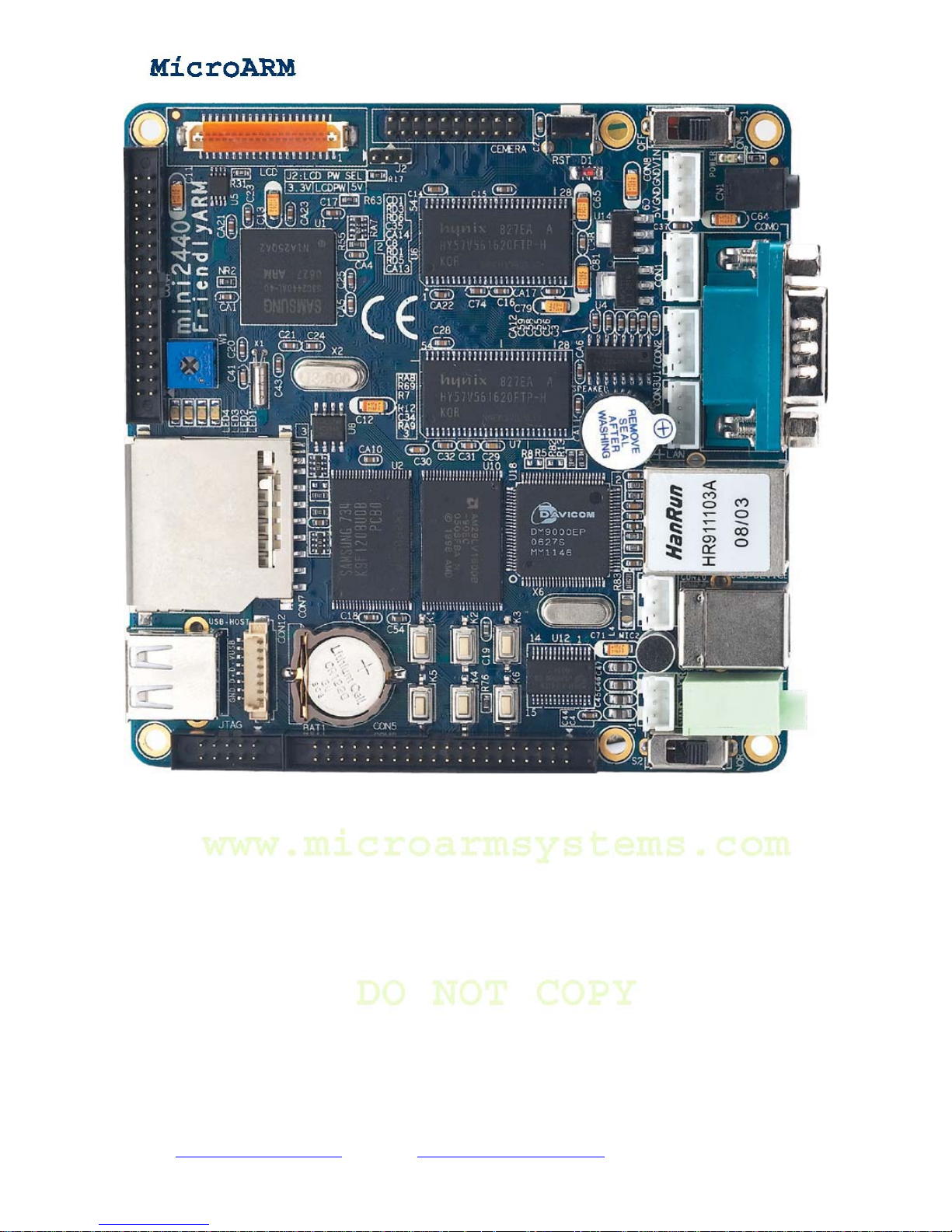
1.3.1 What a MINI2440 Development Board Looks Like
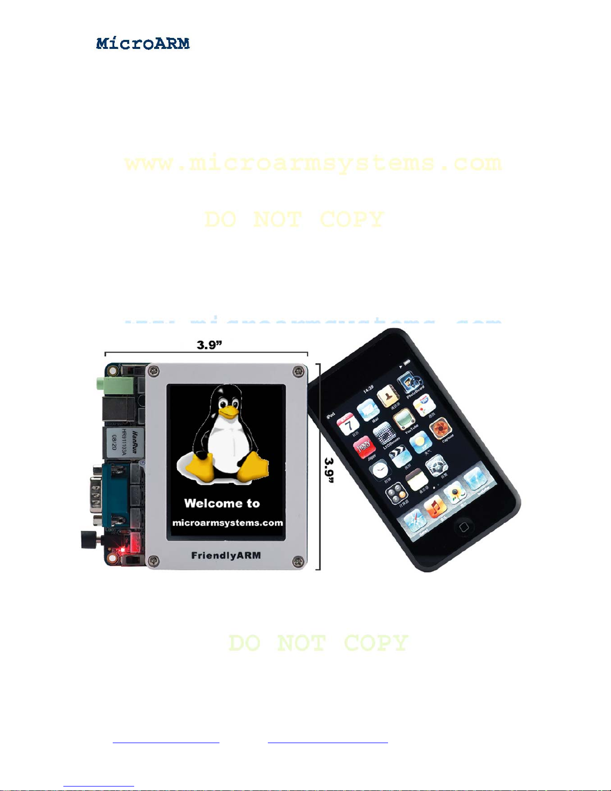
The MINI2440 development board is a 100 x 100(mm) board equipped with a wide variety of
connectors, interfaces and ports.
Page 8
High Performance Low Cost Embedded Systems
1.3.2 MINI2440 Hardware Features
CPU
- Samsung S3C2440A,400MHz,maximum 533Mhz
SDRAM
- On board 64M SDRAM
- 32bit Data Bus
- SDRAM, maximum clock frequency 100MHz
FLASH Memory
- On board 64M Nand Flash
- On board 2M Nor Flash with preinstalled BIOS
LCD
- Four-wire touch screen interface
Copy right reserved © MicroArm Systems, Inc. 1612 2
nd
Ave. SW PMB#108, Cullman, AL 35055 - 8 -
Website : www.microarmsystems.com Email: [email protected] Phone: 1-888-417-9266
Page 9
High Performance Low Cost Embedded Systems
Copy right reserved © MicroArm Systems, Inc. 1612 2
nd
Ave. SW PMB#108, Cullman, AL 35055 - 9 -
Website : www.microarmsystems.com Email: [email protected] Phone: 1-888-417-9266
- Support black and white, 4 level grayscale, 16 level grayscale, 256-color、4096-color STN
LCD, 3.5-inch to 12.1-inch, screen resolution 1024x768;
- Support black and white, 4 level grayscale, 16 level grayscale, 256-color, 64K-color, true
color TFT LCD, 3.5-inch to 12.1-inch, screen resolution 1024x768,
- NEC 256K color 240x320/3.5-inch TFT true color touch screen,
- 12 V power supply interface, it is for 12V CCFL backlight modules of big size TFT LCDs
1.3.3 Interfaces and External Accessories
Interfaces and External Accessories
- 100M Ethernet RJ-45 port (powered by the DM9000 network chip)
- 3 serial ports
- USB Host port
- USB Slave B port
- SD card interface
- Single stereo audio output and single microphone interface
- 2.0mm 10 pin JTAG interface
- 4 USER LEDs
- 6 USER Buttons (with leads to block)
- PWM buzzer
- Adjustable resistor, for AD conversion
- AT24C08 chip with I2C Bus, for I2C Bus test
- 2.0 mm 20pin video camera interface
- Onboard real-time clock backup battery
- 5V power supply interface, with power switch and led
System Clock Source
- 12M passive crystal oscillator
Real-Time Clock
- RTC with lithium battery backup
Extended Interfaces
- 34 pin 2.0mm GPIO port
- 40 pin 2.0mm system bus interface
1.3.4 OS Support
The MINI2440 development board currently supports Linux 2.6.29 and WinCE.NET 5.0.
1.3.4.1 Linux Features
Kernel Version
- Linux 2.6.29
File Systems
- YAFFS2
- CRAMFS
- EXT2
- FAT32
Page 10
High Performance Low Cost Embedded Systems
Copy right reserved © MicroArm Systems, Inc. 1612 2
nd
Ave. SW PMB#108, Cullman, AL 35055 - 10 -
Website : www.microarmsystems.com Email: [email protected] Phone: 1-888-417-9266
- NFS
Drivers (all open source)
- Drivers for 3 serial ports
- DM9000 driver
- Audio driver (UDA1341) (audio recording supported)
- RTC driver
- User LED driver
- USB host driver
- True color LCD driver (including 1024 x 768 VGA)
- Touch screen driver
- USB camera driver
- Drivers for USB mouse, keyboard, flash drive and portable hard disk
- SD card driver, supports maximum memory of 32 G
- I2C-EEPROM driver
- PWM buzzer driver
- LCD backlight driver
- A/D converter driver
- Watchdog driver (watchdog reset is cold reset)
Linux Applications and Utilities
- Busybox1.13 (Linux tool kit including basic Linux commands)
- Telnet, FTP and inetd (remote login tool)
- BOA (web server)
- Madplay (console based mp3 player)
- Snapshot (console based screen print tool)
- ifconfig, ping, route and so on (basic network commands)
Graphic User Interface (Open Source)
- Qt/Embedded 2.2 (x86 and arm)
Qtopia Test Utilities (developed by FriendlyARM, not open source)
- A/D conversion test tool
- LED test tool
- User button test tool
- I2C-EEPROM read/write test tool
- LCD test tool
- Ping test tool
- USB camera live preview and picture taking
- Audio recorder
- Web browser
- Watchdog test tool
- Network configuration tool
- Backlight control tool
- Language setting tool (English and Chinese)
- Handwriting tool (for touch pen testing)
- MMC/SD card and flash drive auto mounting and unmounting
Page 11
High Performance Low Cost Embedded Systems
Copy right reserved © MicroArm Systems, Inc. 1612 2
nd
Ave. SW PMB#108, Cullman, AL 35055 - 11 -
Website : www.microarmsystems.com Email: [email protected] Phone: 1-888-417-9266
1.3.4.2 WinCE Features
Version
- Windows CE.net 5.0
Features
- DM9000 driver source code
- Drivers for USB keyboard, mouse, flash drive and portable hard disks
- Drivers for 3 serial ports
- USB ActiveSync
- Audio driver
- SD card driver
- RTC clock
- Registry archive
- Power-down data save in flash drive
- Screen rotation
Default System Options (Simplified Chinese System)
- XP screen
- Windows Media Player 9.0 (supporting mp3, mpeg2, mpeg4, wma, wav and so on)
- Super player (video player)
- Picture browser and word pad
- IE6
- FTP, TELNET and HTTPD
- Serial port assistant
1.3.5 Additional Resources
Please refer to Appendix A for the resources included in the shipped CD and Appendix B for the
device schematics.
Page 12
High Performance Low Cost Embedded Systems
Copy right reserved © MicroArm Systems, Inc. 1612 2
nd
Ave. SW PMB#108, Cullman, AL 35055 - 12 -
Website : www.microarmsystems.com Email: [email protected] Phone: 1-888-417-9266
Chapter 2 Getting Started
2.1 System Setup and Configurations
2.1.1 Boot Options
You can select the booting mode by toggling the S2 switch:
When toggling the S2 switch to the “Nor Flash” side the system will boot from on board Nor
Flash. When toggling the S2 switch to the “Nand Flash” side the system will boot from on board
Nand Flash.
This board is shipped with the switch toggled to the Nand Flash side by default it will boot from
Nand Flash. Both its Nor Flash and Nand Flash have been installed an identical BIOS (which
supports both types of Flash. The only difference is that the system will have different startup
windows).
2.1.2 Connecting Peripherals
Connect the MINI2440 board’s serial port to a PC’s serial port with the shipped serial
cable in the package
Connect the MINI2440 board’s Ethernet interface to a PC with the shipped crossover
cable
Connect the shipped 5V power supply adapter to the 5V power supply interface on the
board
Connect a headphone or speaker to the audio input(green) on the board
Connect an LCD touch panel (if the user has one) to the LCD interface on the board
following the data bus’ arrow.
Connect the MINI2440 board to a PC with a USB cable.
2.1.3 Setting up Super Terminal
To connect the MINI2440 board to a host PC via a serial cable, you should use a simulated
terminal. There are many tools available. A most widely used one is the MS-Windows’ super
terminal. In Windows9x, you need to install it by checking that option during installation.
Windows2000 and later versions already have it installed by default. We used the super terminal in
Windows XP in all our examples in this manual (Other versions of super terminal might have
different user interfaces). Go to “Start” -> “All Programs” -> “Accessories” -> “Communications”.
Page 13
High Performance Low Cost Embedded Systems
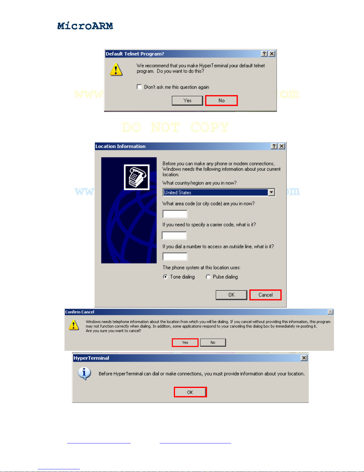
Click on “Hyper Terminal” and a Window will pop up as below. Click on the “No” button
Click on the “Cancel” button on the following window
Click on the “Yes” button and the “OK” button to the next step
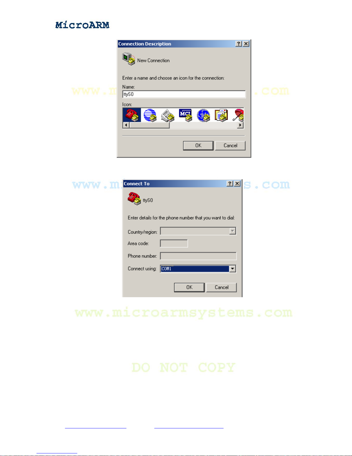
A popup window will require you to name this connection. In this example we typed “ttyS0”.
Windows does not accept names like “COM1” th at have already been used by the system.
Copy right reserved © MicroArm Systems, Inc. 1612 2
nd
Ave. SW PMB#108, Cullman, AL 35055 - 13 -
Website : www.microarmsystems.com Email: [email protected] Phone: 1-888-417-9266
Page 14
High Performance Low Cost Embedded Systems
After naming this connection another window will require you to select a serial port that will be
used to connect the MINI2440 board. Here we selected COM1:
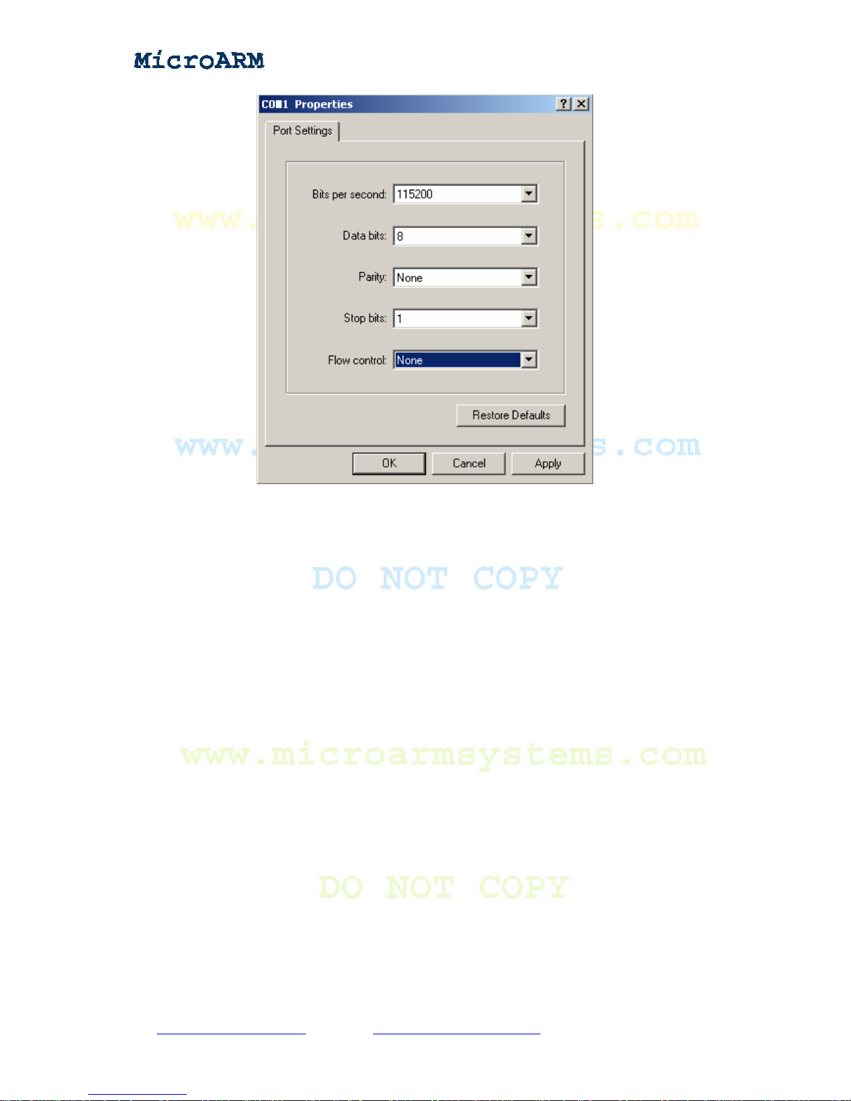
Lastly, also the most important step is to set up the port properties. Note: you must select “No” in
the data flow control field otherwise you will only be able to see outputs. In addition the bits per
second should be set to 115200.
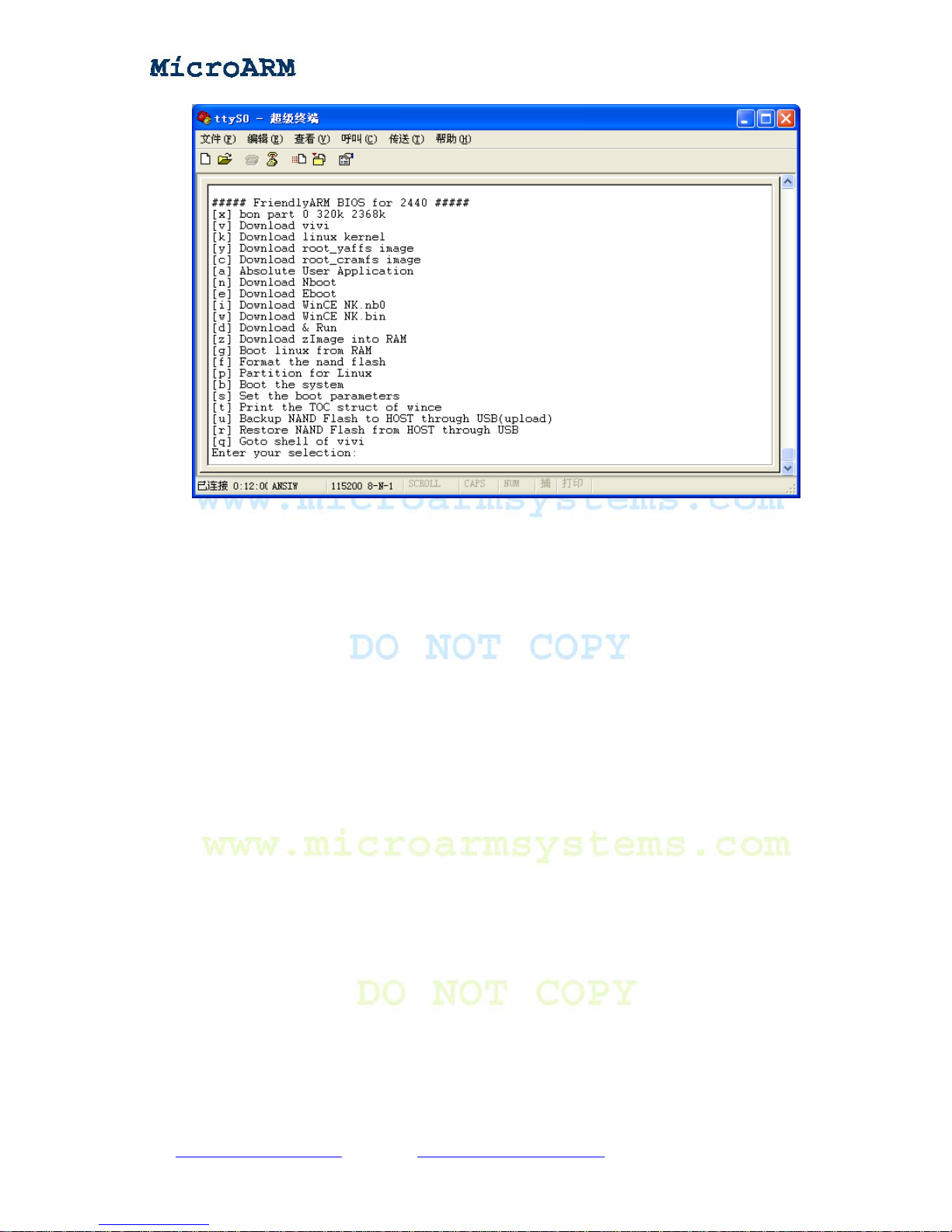
After setting up all properties, turn on the board’s power supply, if the connection gets set
properly, you will see a VIVI startup interface. If everything runs fine, please save this connection
for later use
Copy right reserved © MicroArm Systems, Inc. 1612 2
nd
Ave. SW PMB#108, Cullman, AL 35055 - 14 -
Website : www.microarmsystems.com Email: [email protected] Phone: 1-888-417-9266
Page 15
High Performance Low Cost Embedded Systems
2.2 Power Up
2.2.1 Entering BIOS
The board is shipped with a preinstalled SUPERVIVI in Nor Flash. When the system boots from
Nor Flash it will enter the BIOS and in the meantime the green LED1 on the board will be
flashing. The startup interface is as below:
Copy right reserved © MicroArm Systems, Inc. 1612 2
nd
Ave. SW PMB#108, Cullman, AL 35055 - 15 -
Website : www.microarmsystems.com Email: [email protected] Phone: 1-888-417-9266
Page 16
High Performance Low Cost Embedded Systems
SUPERVIVI is developed and maintained by Friendly Arm, it is based on vivi. It starts with a
function menu. And users can switch between supervivi’s menu interface and command line.
Supervivi can be burned into the Nor Flash with JTAG or run from the Nand Flash. When it is
burned into the Nor Flash and run, users will see its menu. When it is run from the Nand Flash it
will start as command line (note: users need to press down and hold the space key in the super
terminal on system startup otherwise the system will boot to its installed operating system).
Supervivi is mainly for software burning and debugging, and can be used to partition flash drive. It
downloads files via USB. It is easy to use and runs fast. When burning supervivi into the Nor Flash,
you can easily update your Linux or WinCE system, or any other operating system that supports
system boot from the Nand Flash and non OS programs to the Nand Flash such as uCos2, U-boot,
Nboot, 2440test and so on, and then reboot system from the Nand Flash to enjoy your programs.
When burning supervivi to the Nand Flash, it will self detect your operating system and start it. In
addition, with its “Down & Run” function, you can download programs to RAM and run them. This
features software debugging such that you don’t need a simulator. The 2440test utility in the
shipped CD is such a good example.
With supervivi, you can download the Linux kernel image zImage into RAM and run it. You can
even start your system via network by setting up the network boot parameters in supervivi.
Similarly, you can download the WinCE kernel image NK.nb0 to RAM and run it too.
2.2.2 Installing USB Driver
Note: the driver installed here can only work for a USB connection in the BIOS mode. It should
work in conjunction with the dnw.exe executable. After the system enters Linux or WinCE, the
Copy right reserved © MicroArm Systems, Inc. 1612 2
nd
Ave. SW PMB#108, Cullman, AL 35055 - 16 -
Website : www.microarmsystems.com Email: [email protected] Phone: 1-888-417-9266
Page 17
High Performance Low Cost Embedded Systems
driver will no longer be used.
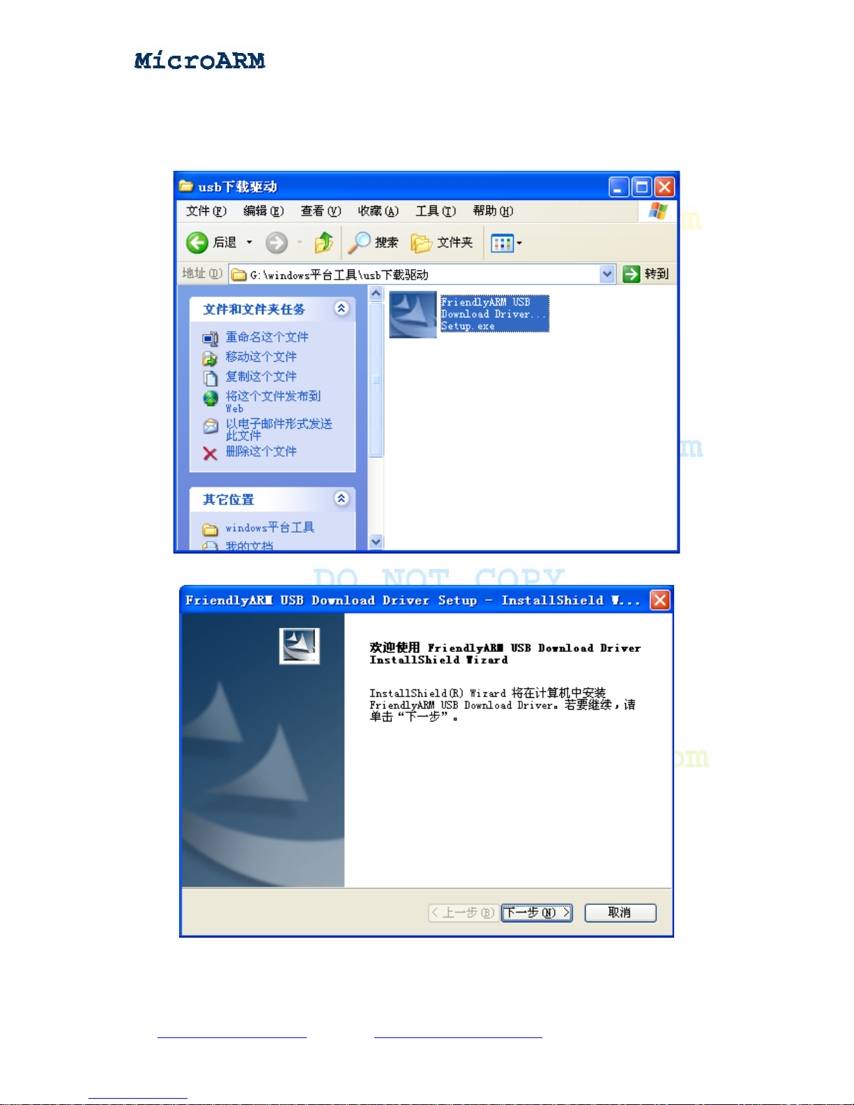
Installing this USB driver doesn’t need to connect to a board. It is just for the PC system.
Open the shipped CD, double click on “windows 平台工具\usb 下载驱动\ FriendlyARM
USB Download Driver Setup_20090421.exe” to start installing.
The following window will show up:
Click on (“Next”)the middle button.
Copy right reserved © MicroArm Systems, Inc. 1612 2
nd
Ave. SW PMB#108, Cullman, AL 35055 - 17 -
Website : www.microarmsystems.com Email: [email protected] Phone: 1-888-417-9266
Page 18
High Performance Low Cost Embedded Systems
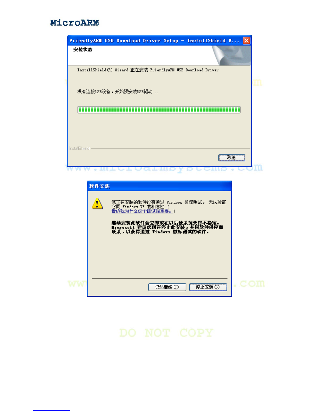
A warning message will pop up
Click on the (“continue anyway”) the left button to finish the installation.
Copy right reserved © MicroArm Systems, Inc. 1612 2
nd
Ave. SW PMB#108, Cullman, AL 35055 - 18 -
Website : www.microarmsystems.com Email: [email protected] Phone: 1-888-417-9266
Page 19
High Performance Low Cost Embedded Systems
Now let’s test the USB connection:
Connect the MINI2440 board to a host PC via a USB cable. Toggle the S2 switch to the
“Nor Flash” side.
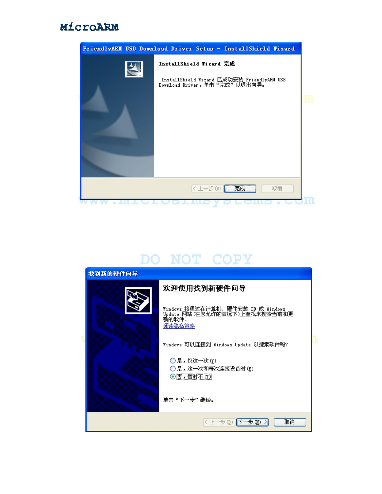
Turn on the S1 switch, if this is the first time you connect, Windows XP will prompt that a new
USB device is found. Follow the steps below to install a USB driver:
(1) After the following window pops up, check the third option and click on the “Next” button
Copy right reserved © MicroArm Systems, Inc. 1612 2
nd
Ave. SW PMB#108, Cullman, AL 35055 - 19 -
Website : www.microarmsystems.com Email: [email protected] Phone: 1-888-417-9266
Page 20
High Performance Low Cost Embedded Systems
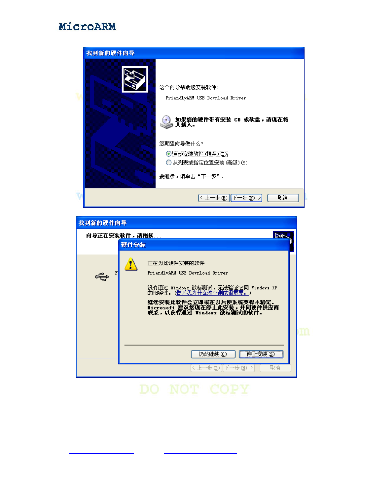
(2) On the window shown below, check the first option and click on the “Next” button
On the following popup window, click on the left button (“Continue anyway”).
So far, our installation is done.
Copy right reserved © MicroArm Systems, Inc. 1612 2
nd
Ave. SW PMB#108, Cullman, AL 35055 - 20 -
Website : www.microarmsystems.com Email: [email protected] Phone: 1-888-417-9266
Page 21
High Performance Low Cost Embedded Systems
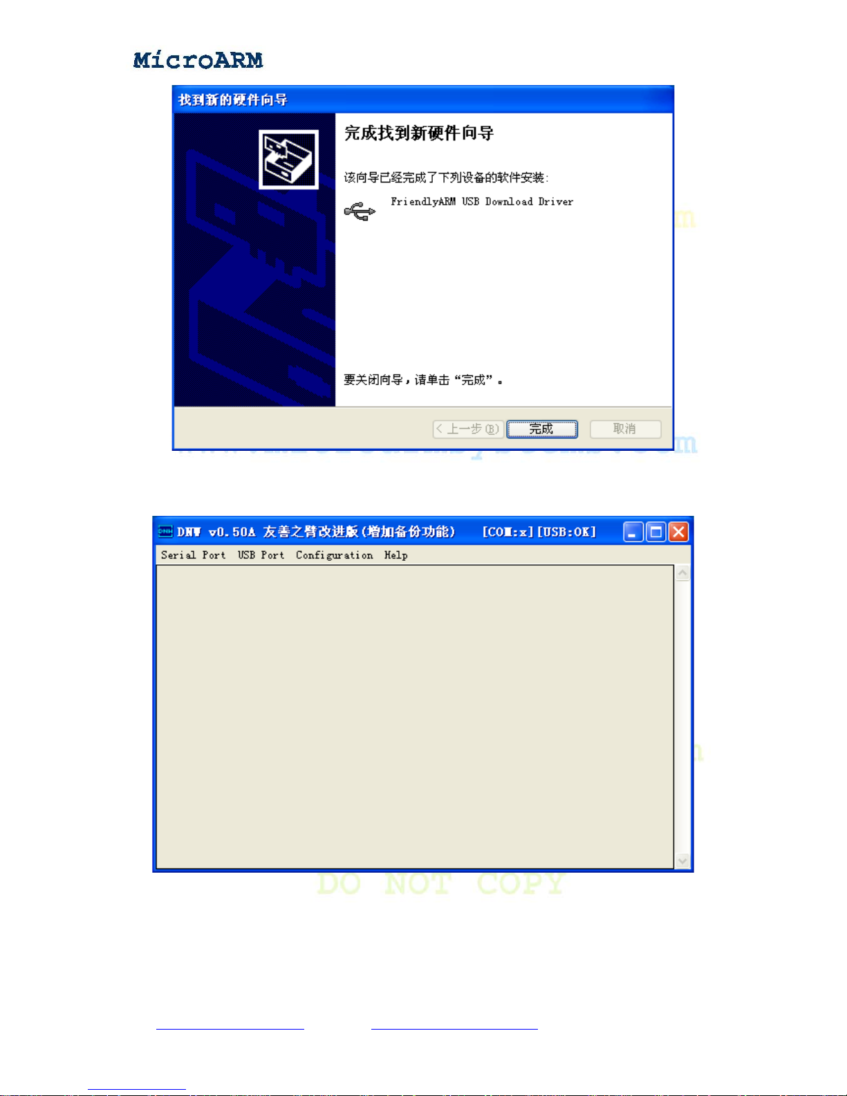
Open the shipped CD, click on the dnw.exe, if you can see “USB:OK”, this means the installation
is a success.
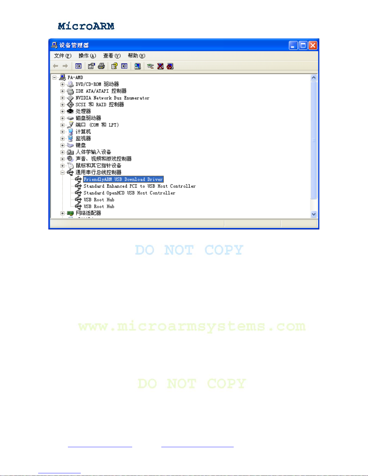
In the device manager, you will see the installed USB driver information:
Copy right reserved © MicroArm Systems, Inc. 1612 2
nd
Ave. SW PMB#108, Cullman, AL 35055 - 21 -
Website : www.microarmsystems.com Email: [email protected] Phone: 1-888-417-9266
Page 22
High Performance Low Cost Embedded Systems
2.2.3 Entering Main Menu
Note: the following programs that are downloaded via USB need to run together with the
DNW application.
Copy right reserved © MicroArm Systems, Inc. 1612 2
nd
Ave. SW PMB#108, Cullman, AL 35055 - 22 -
Website : www.microarmsystems.com Email: [email protected] Phone: 1-888-417-9266
Page 23
High Performance Low Cost Embedded Systems
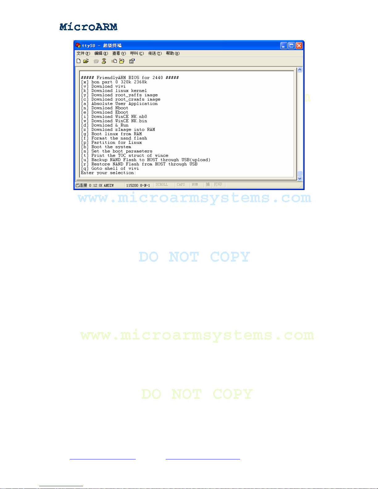
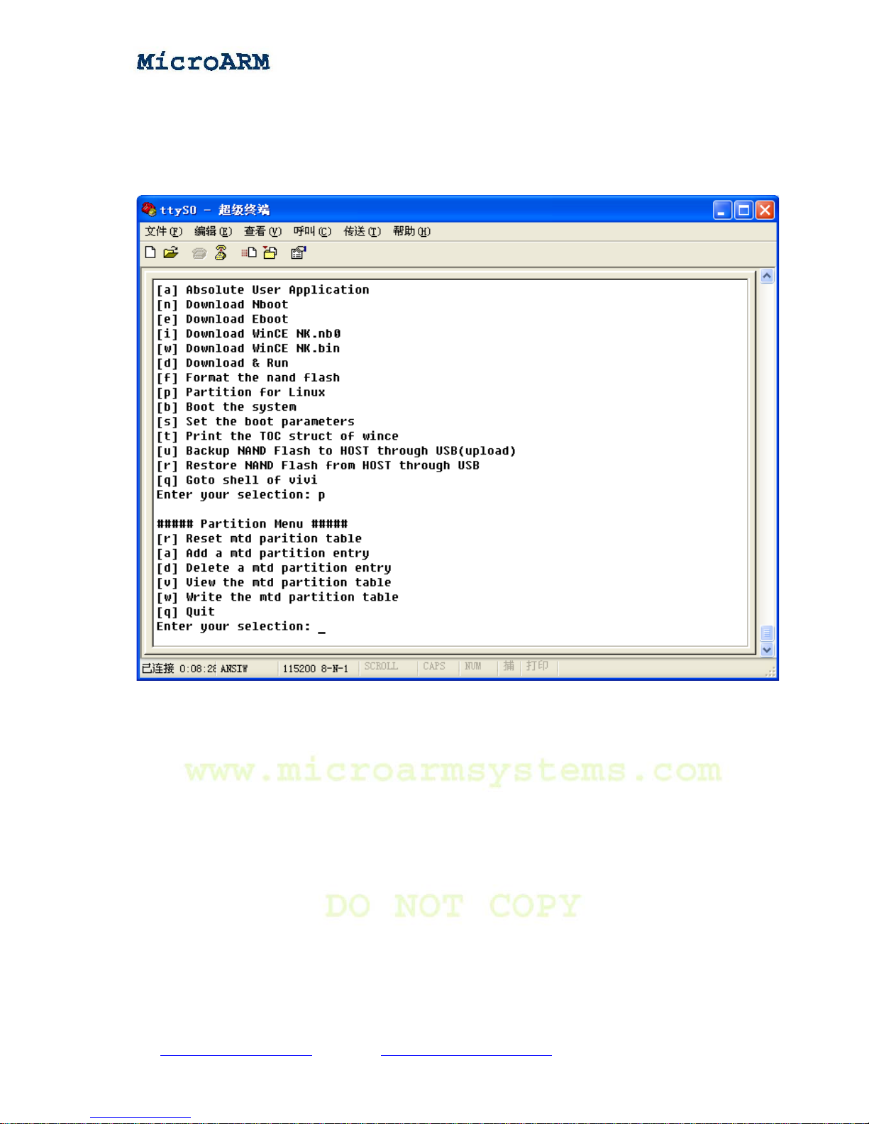
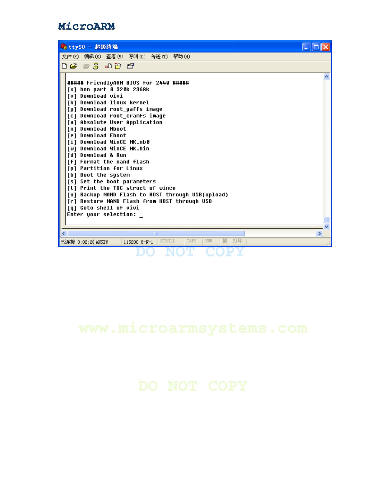
Item[x]: Partition Nand Flash with a default setting, it is the same as executing command:
bon part 0 320k 2368k
Item[v]: Download a linux bootloader vivi to the vivi partition of Nand Flash via USB
Item[k]: Download a linux kernel to the kernel partition of Nand Flash via USB
Item[y]: Download an image of the yaffs file system to the root partition of Nand Flash via
USB
Item[c]: Download an image of the cramfs file system to the root partition of Nand Flash
via USB
Item[a]: Download a user application to Nand Flash via USB, usually it is a bin file, such
as “2440test”, uCos2(our shipped uCos2 supports booting from Nand Flash), U-Boot and other bin
programs.
Item[n]: Download a WinCE’s bootloader Nboot to block0 of Nand Flash via USB
Item[e]: Download a WinCE’s bootloader Eboot to the Eboot partition of Nand Flash via
USB
Item[i]: Download an image of WinCE NK.nb0 to Nand Flash via USB
Item[w]: Download an image of WinCE NK.bin to Nand Flash via USB
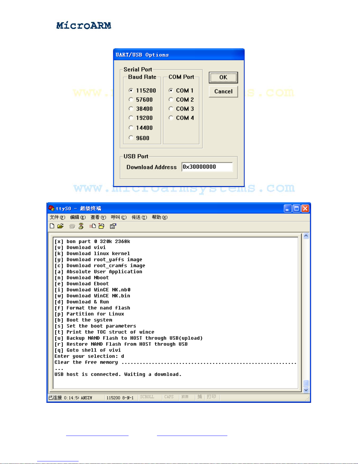
Item[d]: Download a program to a user defined address(via the DNW’s “Configuration” ->
“Option” to define a download address) and run. The SDRAM’s physical address in this board is
from 0x30000000 to 0x34000000, 64Mbytes. The BIOS takes all the address space above
0x33DE8000, so the user defined address should be between 0x30000000 and 0x33DE8000.
Item[z]: Download a linux kernel zImage to RAM via USB. The download address is
0x30008000.
Item[g]: Boot linux from RAM. Item [z] should be executed before this.
Item[f]: Format Nand Flash. This command will format the specified address space of
Nand Flash. The on board Nand Flash is 64Mbytes. Its address space is 0-0x4000000. You can
format one partition or the whole Nand Flash. The partition table is as follows:
Copy right reserved © MicroArm Systems, Inc. 1612 2
nd
Ave. SW PMB#108, Cullman, AL 35055 - 23 -
Website : www.microarmsystems.com Email: [email protected] Phone: 1-888-417-9266
Page 24
High Performance Low Cost Embedded Systems
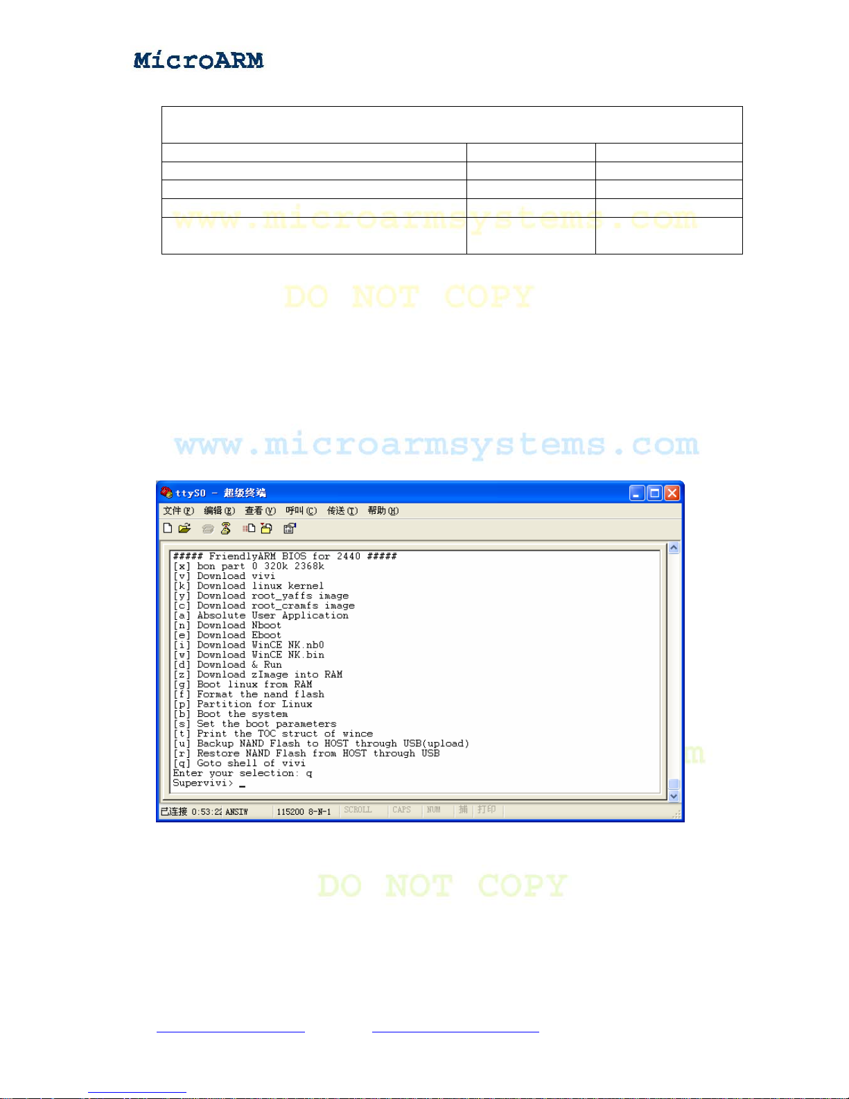
Partition T able
Type “f”, you will be prompted to type a starting address and a end address, this table
presents the address space of each partition
Srarting Address End Address
vivi partitions(block0-13) 0x0 0x50000
linux kernel partitions(block14-93) 0x50000 0x250000
file system partitions(block94-4095) 0x250000 0x4000000
complete address space of the Nand
Flash(block0-4095)
0x0 0x4000000
Note:The on board Nand Flash has 4096 blocks,each block has 32 pages,each page
has 512 bytes,the total size is: 4096 x 32 x 512 = 64M bytes
Item[p]: Partition Nand Flash, this is for Linux
Item[b]: Boot OS (either a Linux or a WinCE).
Item[s]: Set up Linux startup parameters
Item[t]: Print the TOC structure of WinCE (rarely used)
Item[u]: Backup Nand Flash data to a host PC via USB. This is similar to a Ghost tool
commonly used in PCs.
Item[r]: Restore Nand Flash from a host via USB.
Item[q]: Return to the vivi shell
In the vivi shell, typing “menu” can return to the main menu.
Copy right reserved © MicroArm Systems, Inc. 1612 2
nd
Ave. SW PMB#108, Cullman, AL 35055 - 24 -
Website : www.microarmsystems.com Email: [email protected] Phone: 1-888-417-9266
Page 25
High Performance Low Cost Embedded Systems
2.2.4 Sub Menus
This section will briefly introduces some submenu functions
Type “p” to enter the interface shown below:
(1) browsing partitions
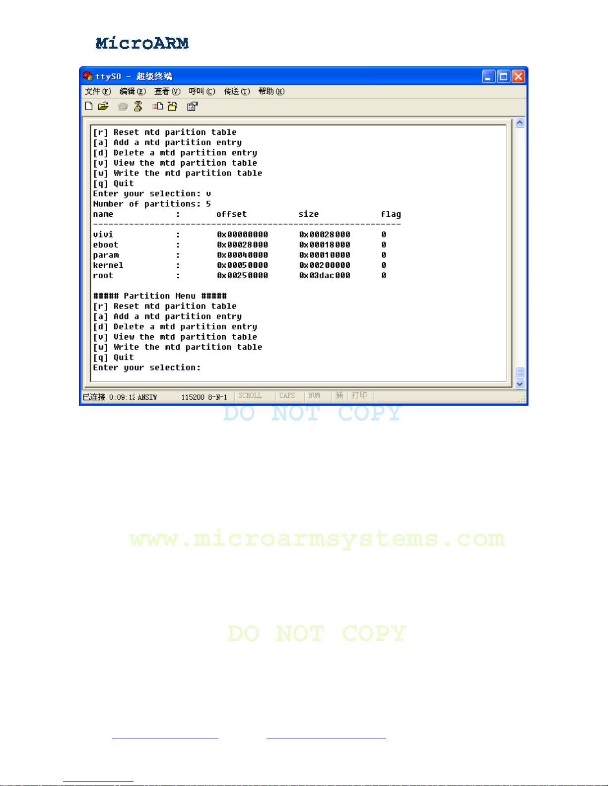
T ype “v” to browse the curren t partition table, which is stored in the Na nd Flash. If the Nand Flash
has no data, it will show the default BIOS partition table.
Copy right reserved © MicroArm Systems, Inc. 1612 2
nd
Ave. SW PMB#108, Cullman, AL 35055 - 25 -
Website : www.microarmsystems.com Email: [email protected] Phone: 1-888-417-9266
Page 26
High Performance Low Cost Embedded Systems
(2) deleting partitions
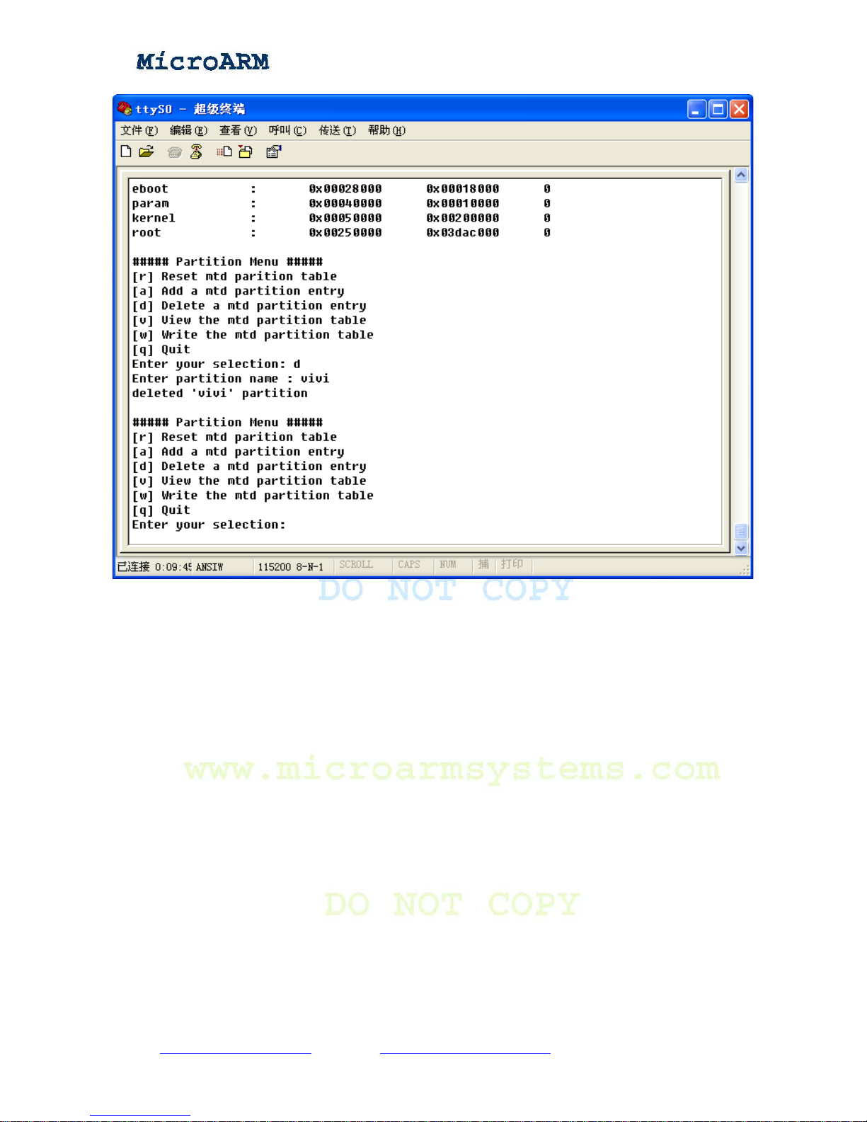
T ype “d”, it will prompt you to enter the partition’s name you want to delete, e.g. “vivi” if you want
to delete the vivi partition
Copy right reserved © MicroArm Systems, Inc. 1612 2
nd
Ave. SW PMB#108, Cullman, AL 35055 - 26 -
Website : www.microarmsystems.com Email: [email protected] Phone: 1-888-417-9266
Page 27
High Performance Low Cost Embedded Systems
(3) saving configurations
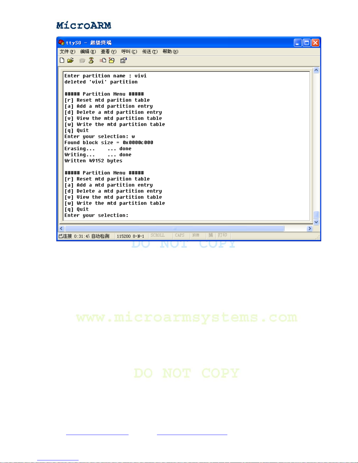
Type “w” to save the current configuration. For instance, if you just deleted the vivi partition
without saving it, next time when you browse the partition, it will still exist.
Copy right reserved © MicroArm Systems, Inc. 1612 2
nd
Ave. SW PMB#108, Cullman, AL 35055 - 27 -
Website : www.microarmsystems.com Email: [email protected] Phone: 1-888-417-9266
Page 28
High Performance Low Cost Embedded Systems
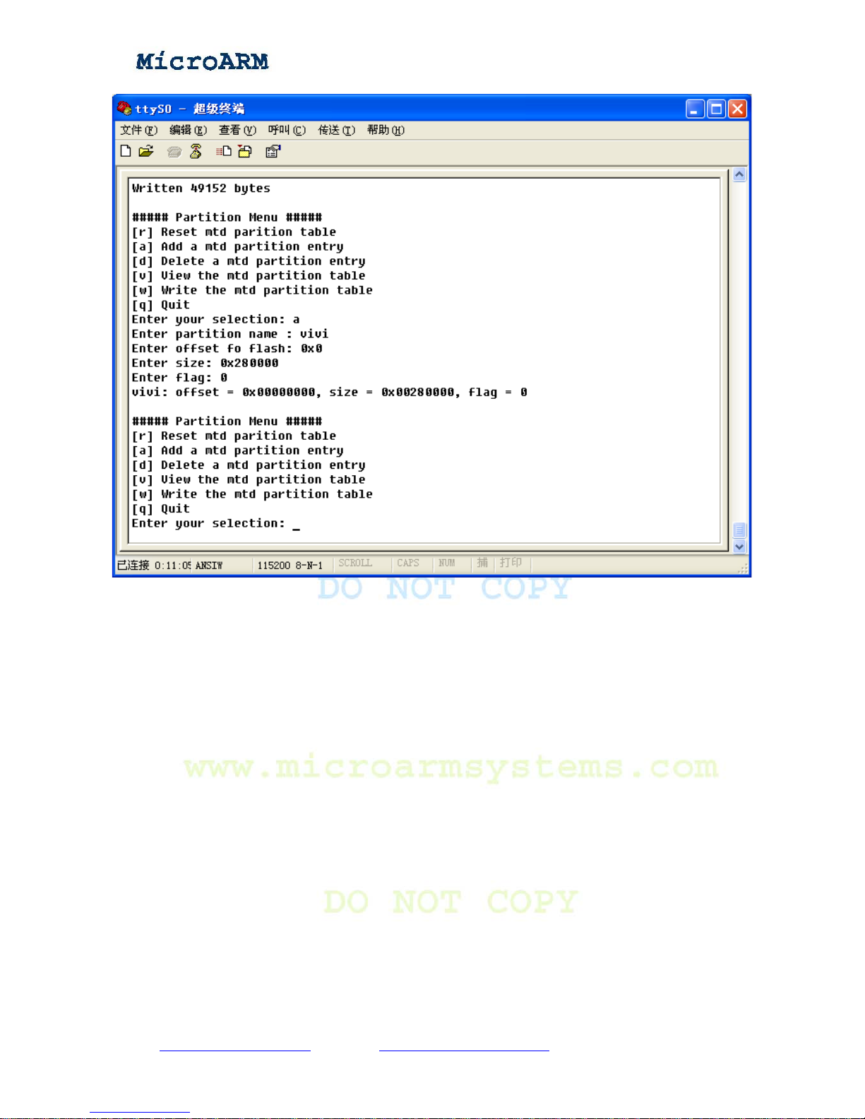
(4) adding partitions
Type “a”, it will prompt you to enter some basic information (such as n ame, offset, size and so on)
of the partition you want to add. You can just follow its default options.
Copy right reserved © MicroArm Systems, Inc. 1612 2
nd
Ave. SW PMB#108, Cullman, AL 35055 - 28 -
Website : www.microarmsystems.com Email: [email protected] Phone: 1-888-417-9266
Page 29
High Performance Low Cost Embedded Systems
(5) resetting partition table
Type “r” to import the BIOS partition table and the current table will be overwritten. When you
delete your Linux partition table by mistake, this command will restore it. After restoring our Linux
partition you need to enter “w” to save this result.
(6) returning to the main menu
Type “q” to return to the main menu
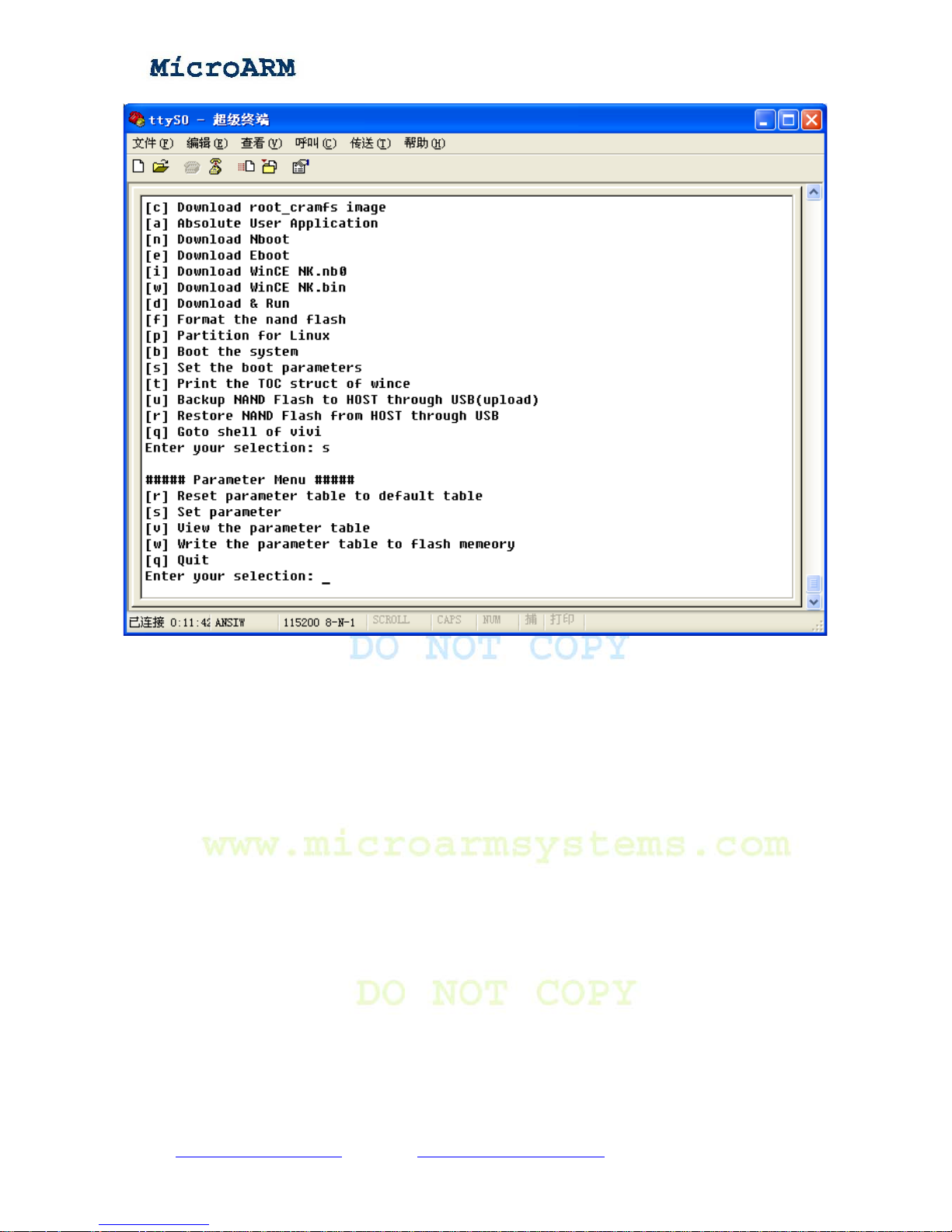
2.2.5 Setting Linux Booting Parameters
Item [s] allows users to configure how Linux should be booted. Type [s] to enter its interface:
Copy right reserved © MicroArm Systems, Inc. 1612 2
nd
Ave. SW PMB#108, Cullman, AL 35055 - 29 -
Website : www.microarmsystems.com Email: [email protected] Phone: 1-888-417-9266
Page 30
High Performance Low Cost Embedded Systems
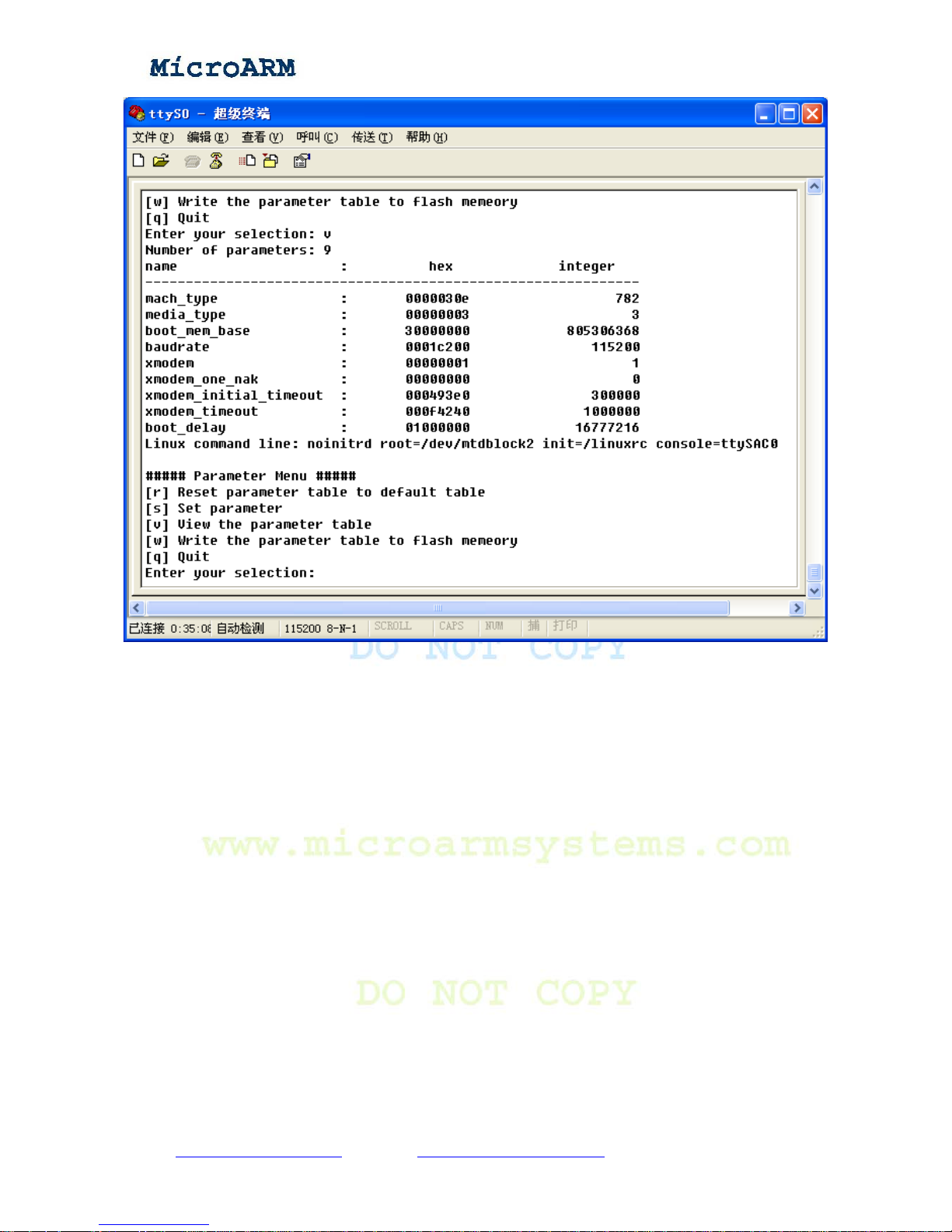
(1) browsing current configuration
Type “v” to browse the current configuration:
Copy right reserved © MicroArm Systems, Inc. 1612 2
nd
Ave. SW PMB#108, Cullman, AL 35055 - 30 -
Website : www.microarmsystems.com Email: [email protected] Phone: 1-888-417-9266
Page 31
High Performance Low Cost Embedded Systems
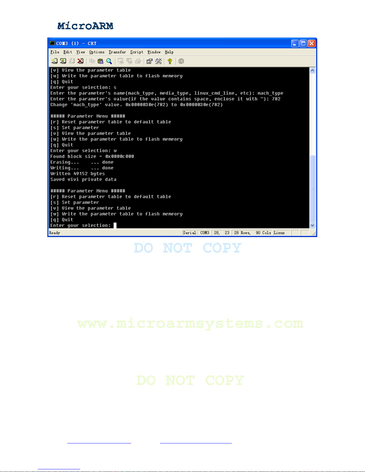
(2) setting parameters
Type “s” to set parameters. There are two basic parameters (we don’t recommend to change other
parameters):
- Match_type
- Linux command line
The default value for MACH_TYPE is 782. For instance, if your compiled kernel’s MACH_TYPE
is 867, you can change this value to boot your kernel. Firstly you need to type the parameter name
“mach_type”, then type the value “867”, and finally, type “w” to save your change.
Copy right reserved © MicroArm Systems, Inc. 1612 2
nd
Ave. SW PMB#108, Cullman, AL 35055 - 31 -
Website : www.microarmsystems.com Email: [email protected] Phone: 1-888-417-9266
Page 32
High Performance Low Cost Embedded Systems
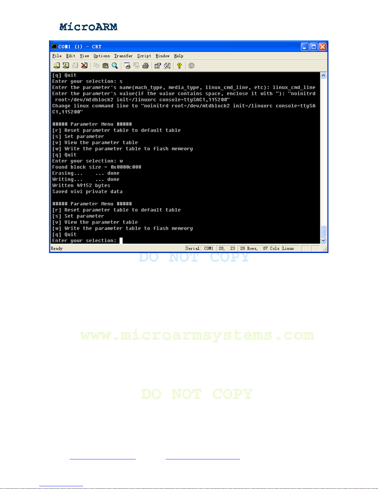
Linux_cmd_line is another very important parameter, for example, to change the kernel boot
information and change the login port to serial port 1 (the default serial port is 0), you can do it this
way:
Linux_cmd_line:noinitrd root=/dev/mtdblock2 init=/linuxrc console=ttySAC0
Type “s”, then the name of the parameter “linux_cmd_line”, enter and then type the new value.
Because the parameter string has spaces, it should be quoted:
“noinitrd root=/dev/mtdblock2 init=/linuxrc console=ttySAC1,115200”
Copy right reserved © MicroArm Systems, Inc. 1612 2
nd
Ave. SW PMB#108, Cullman, AL 35055 - 32 -
Website : www.microarmsystems.com Email: [email protected] Phone: 1-888-417-9266
Page 33
High Performance Low Cost Embedded Systems
Now when the system reboots, the booting and login messages will be output at serial port 1 and
vivi’s messages will still be output at serial port 0.
(3) Saving configuration
Type “w” to save the new setting.
(4) Restoring default value
Type “r” to restore the default kernel setting.
(5) Returning to main menu
Type “q” to return to the BIOS main menu.
2.3 Board Device Testing
This section basically tells how to test some external devices without entering the operating system.
Copy right reserved © MicroArm Systems, Inc. 1612 2
nd
Ave. SW PMB#108, Cullman, AL 35055 - 33 -
Website : www.microarmsystems.com Email: [email protected] Phone: 1-888-417-9266
Page 34
High Performance Low Cost Embedded Systems
Those devices include PWM buzzer, RTC real time clock, AD conversion, user test keys, touch
screen, LCD, Infrared function, I2C bus, audio input/output and SD card.
2.3.1 Downloading Testing Utilities
The 2440test program is an independent utility. It is based on Samsung’s 2440test utility. We just
made some changes for easier use and better experience. In addition we compiled different
executables for varied LCDs. Users can download it to RAM via USB and run it. The only difference
among those executables is the default LCD output. But they all were compiled from the same source
code, we just changed the setting “LCD_TYPE” in the header file “2440test\inc\Option.h”.
File Name Notes Memo
2440test_N35.bin The default output is NEC3.5 inch LCD
2440test_A70.bin The default output is Innolux 7 inch LCD
2440test_VGA1024x768.bin The default output is VGA (resolution
1024 x 768 @ 70 Hz)
But they all are compiled
from the same source
code, we give them a
uniform name “
2440test.bin”.
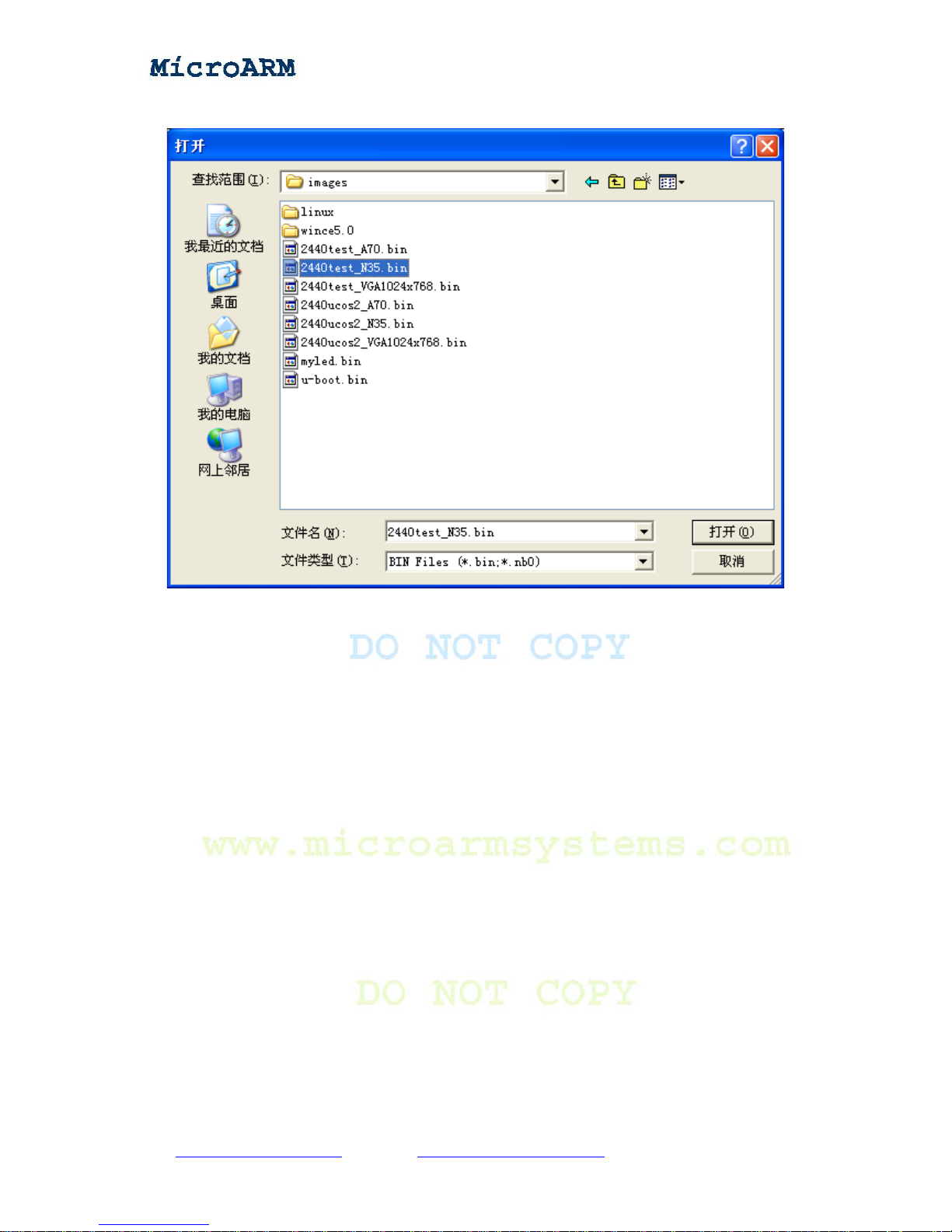
In the “images\” directory of the shipped CD, you will find a “2440test.bin” and download it from
the BIOS interface.
(1) Connect the target board to a power supply, a serial port cable, a USB cable and switch the S2
switch to the Nor Flash boot mode. Start a super terminal and the DNW, power on the board.
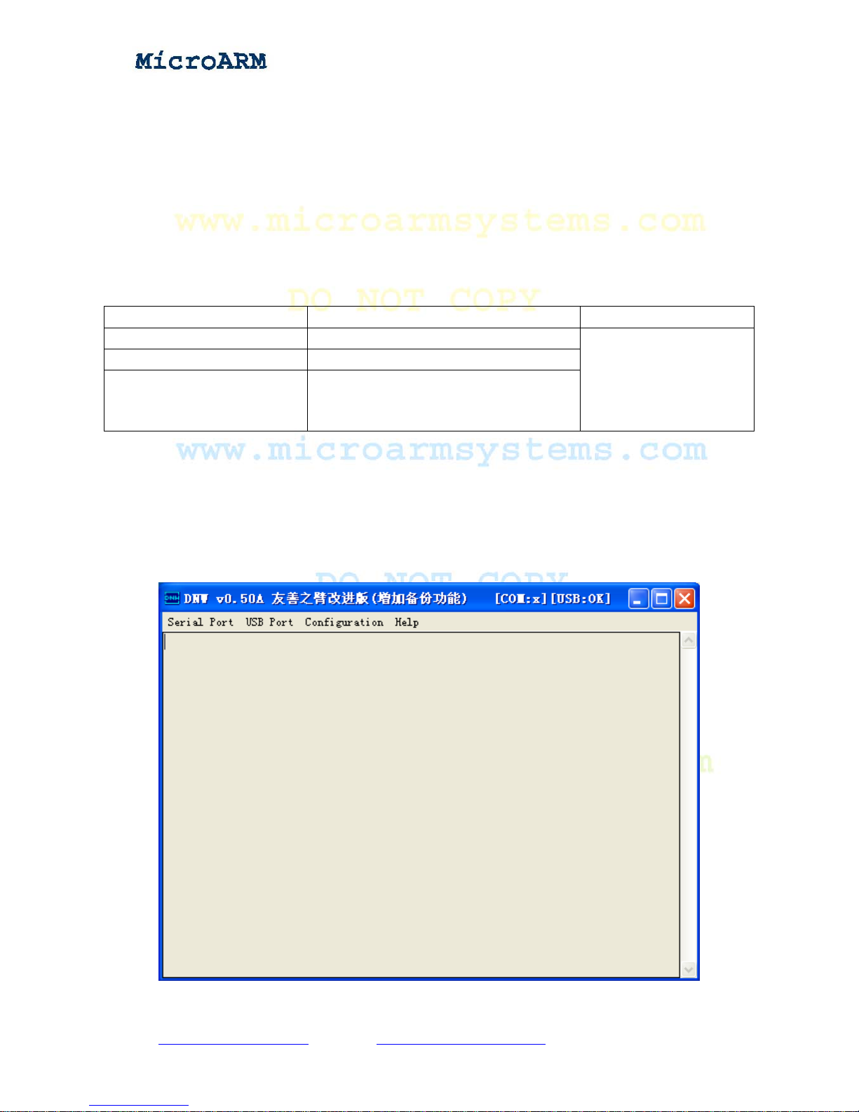
(2) Ensure the USB driver is installed, if so you will see [USB: OK] in the title bar of the DNW
otherwise it will show [USB: x]
Copy right reserved © MicroArm Systems, Inc. 1612 2
nd
Ave. SW PMB#108, Cullman, AL 35055 - 34 -
Website : www.microarmsystems.com Email: [email protected] Phone: 1-888-417-9266
Page 35
High Performance Low Cost Embedded Systems
(3) Click on the “Configuration” menu, set the download address to “0x30000000”.
(4) Select item [d] in the BIOS menu, you will see the following screenshot.
(5) Click on “USB Port” -> “Transmit” on the DNW interface, select “2440test.bin,” and “open”
Copy right reserved © MicroArm Systems, Inc. 1612 2
nd
Ave. SW PMB#108, Cullman, AL 35055 - 35 -
Website : www.microarmsystems.com Email: [email protected] Phone: 1-888-417-9266
Page 36
High Performance Low Cost Embedded Systems
to begin download.
(6) When download is done, it will auto run, you will see the following screenshot
Copy right reserved © MicroArm Systems, Inc. 1612 2
nd
Ave. SW PMB#108, Cullman, AL 35055 - 36 -
Website : www.microarmsystems.com Email: [email protected] Phone: 1-888-417-9266
Page 37
High Performance Low Cost Embedded Systems
Meanwhile, the LCD will show the following picture.
Note: when compiling the 2440test, you can set the “LCD_TYPE” in the header file
“2440test\inc\Option.h” to choose the LCD type, but you cannot define more than one type value,
here our default value is LCD_TYPE_N35, i.e. NEC3.5 inch true color screen.
The header file 2440test\inc\Option.h has the following definitions:
#define LCD_TYPE_N35 1; NEC3.5 inch true color
#define LCD_TYPE_A70 2; 7 inch true color
#define LCD_TYPE_VGA1024x768 3; VGA module, resolution: 1024x768 @70Hz
#define LCD_TYPE LCD_TYPE_N35
If you use the default value, you will see:
Copy right reserved © MicroArm Systems, Inc. 1612 2
nd
Ave. SW PMB#108, Cullman, AL 35055 - 37 -
Website : www.microarmsystems.com Email: [email protected] Phone: 1-888-417-9266
Page 38

High Performance Low Cost Embedded Systems
If the default setting is 7 inch LCD, you will see the following screenshot:
If the default setting is VGA, you will see the following screenshot:
Copy right reserved © MicroArm Systems, Inc. 1612 2
nd
Ave. SW PMB#108, Cullman, AL 35055 - 38 -
Website : www.microarmsystems.com Email: [email protected] Phone: 1-888-417-9266
Page 39

High Performance Low Cost Embedded Systems
2.3.2 Device Testing
After installing the test utility, you can perform the MINI2440 device testing.
(1) Testing PWM
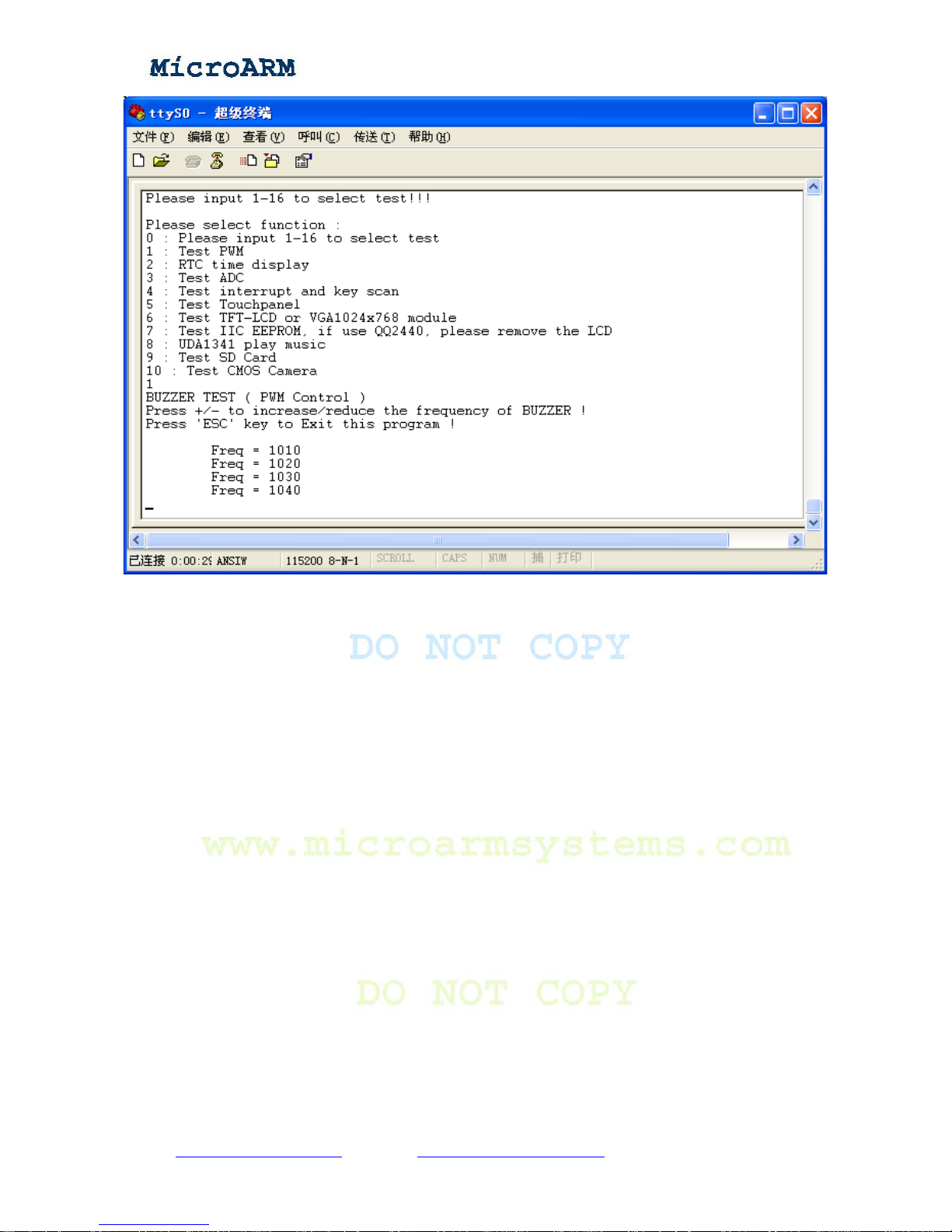
In the main menu, type “1”, enter and you will hear the sound of the PWM buzzer
Copy right reserved © MicroArm Systems, Inc. 1612 2
nd
Ave. SW PMB#108, Cullman, AL 35055 - 39 -
Website : www.microarmsystems.com Email: [email protected] Phone: 1-888-417-9266
Page 40
High Performance Low Cost Embedded Systems
Press the “-” key, the buzzer’s frequency will decrease, press the “+” key; the frequency will
increase; press the “ESC” key, you will exit the test and return to the main menu.
(2) RTC real time clock
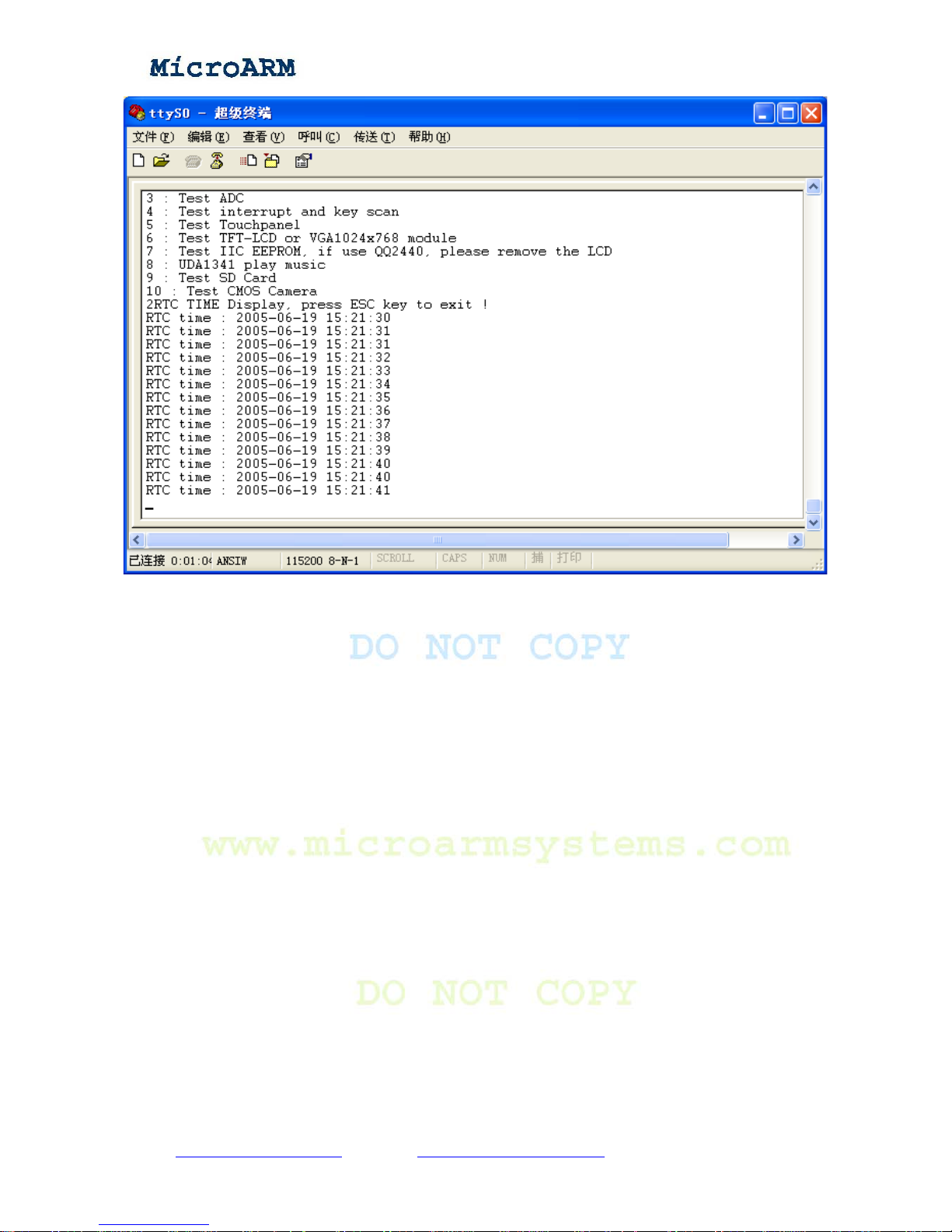
In the main menu, select “2”, enter and you will see the clock is changing which means the CPU’s
R TC works normally (note: the time the clock shows is not the current time, it is initialized by the test
utility)
Copy right reserved © MicroArm Systems, Inc. 1612 2
nd
Ave. SW PMB#108, Cullman, AL 35055 - 40 -
Website : www.microarmsystems.com Email: [email protected] Phone: 1-888-417-9266
Page 41
High Performance Low Cost Embedded Systems
Press the “ESC” key you will exit the test and return to the main menu.
(3) Testing AD conversion
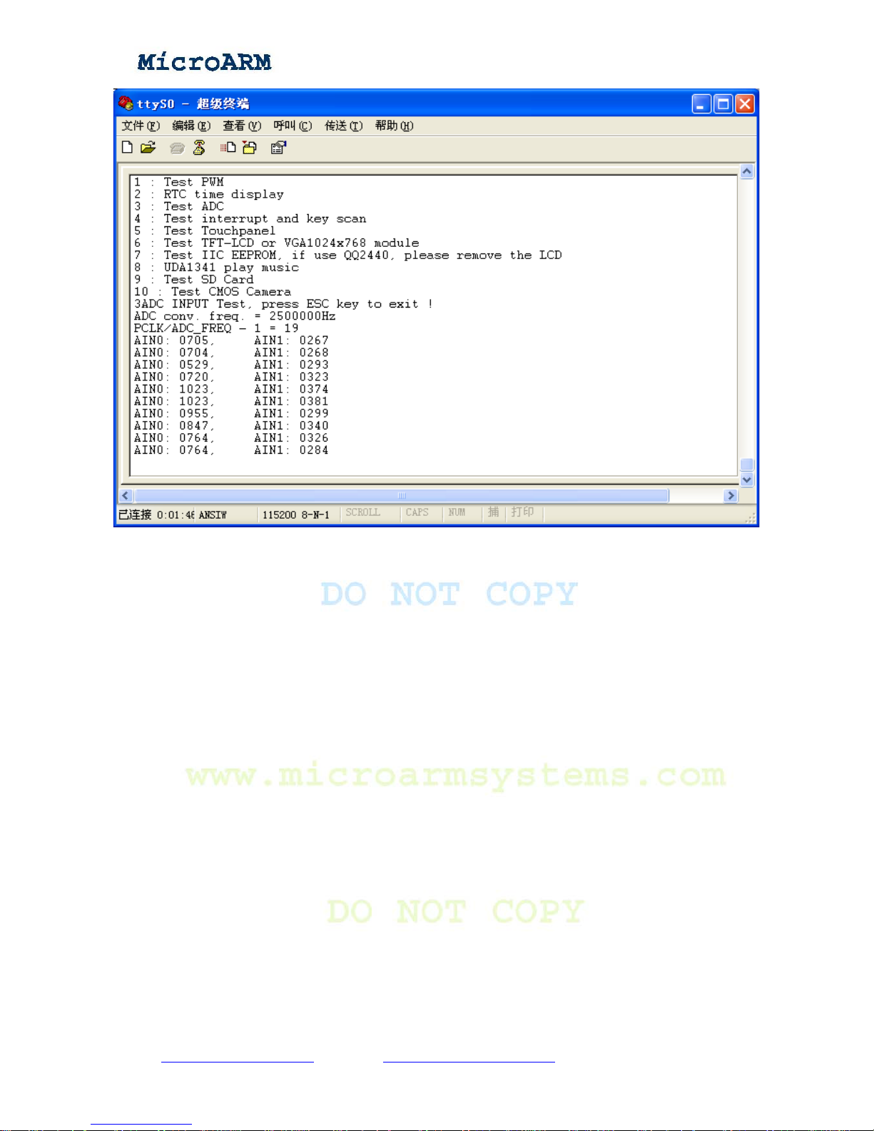
In the main menu, select “3” and enter to test AD conversion. You can use a screw driver to adjust
the W1 or W2 (these two adjustable resistors are connected to AIN0 and AIN1) and will see the AD
value is changing accordingly.
Copy right reserved © MicroArm Systems, Inc. 1612 2
nd
Ave. SW PMB#108, Cullman, AL 35055 - 41 -
Website : www.microarmsystems.com Email: [email protected] Phone: 1-888-417-9266
Page 42
High Performance Low Cost Embedded Systems
Press the “ESC” key you will exit the test and return to the main menu.
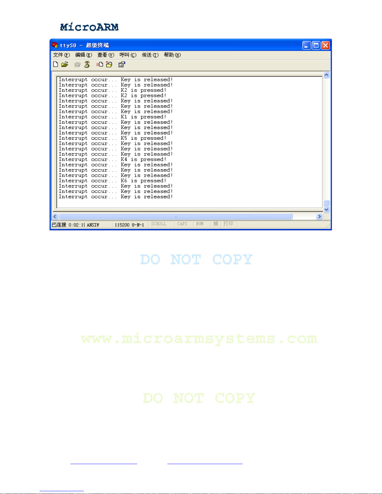
(4) Testing user keys
In the main menu, select “4” and enter to test user keys. Press key K1 – K6, you will see
corresponding key press messages come out from the serial port.
Copy right reserved © MicroArm Systems, Inc. 1612 2
nd
Ave. SW PMB#108, Cullman, AL 35055 - 42 -
Website : www.microarmsystems.com Email: [email protected] Phone: 1-888-417-9266
Page 43
High Performance Low Cost Embedded Systems
Press the “ESC” key you will exit the test and return to the main menu.
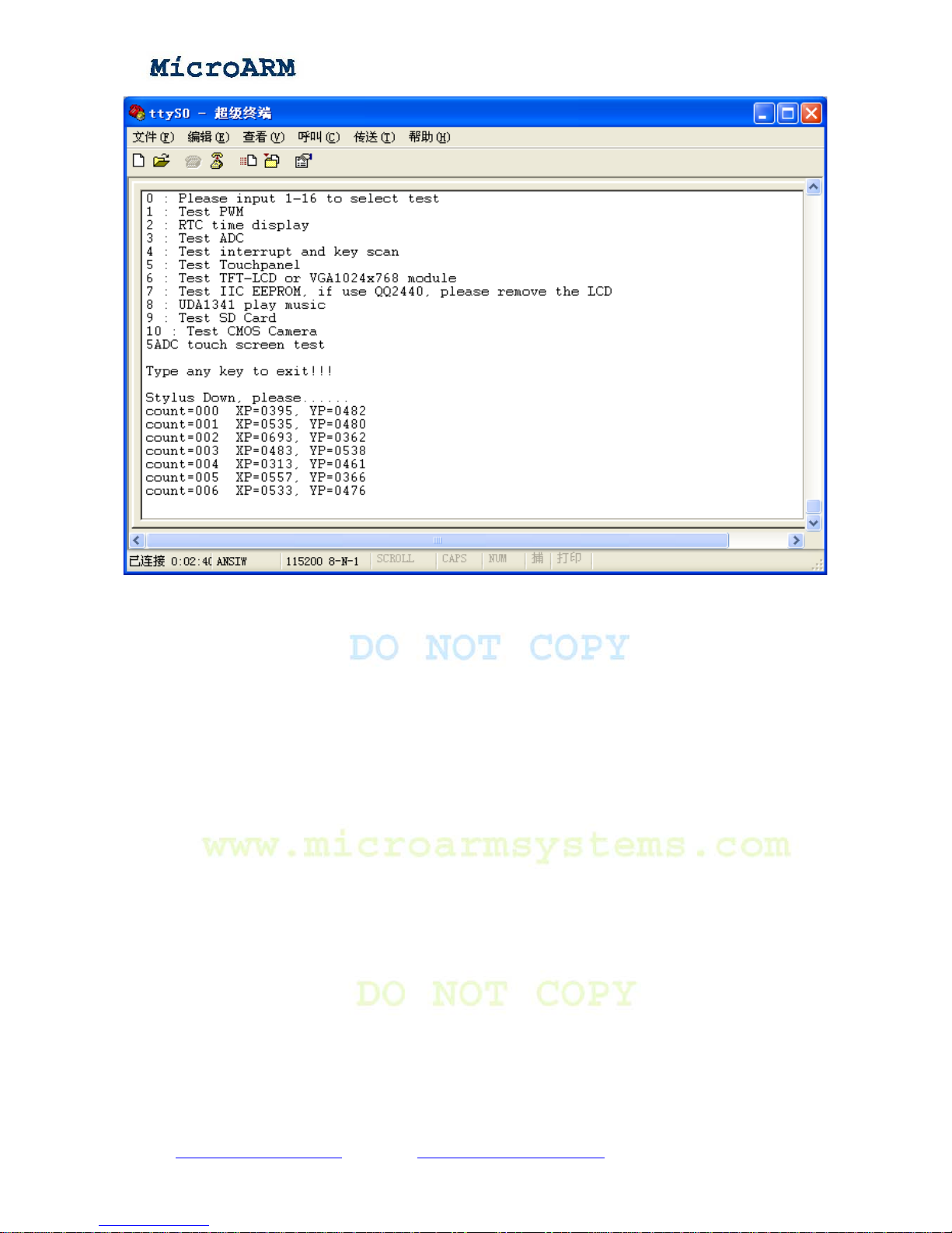
(5) Testing touch screen
If your package has a LCD, you can connect it to your MINI2440 for testing. In the main menu,
select “5” and enter to test. Using a touch pen to click on the touch screen, you will see coordinator
messages come out from the serial port.
Copy right reserved © MicroArm Systems, Inc. 1612 2
nd
Ave. SW PMB#108, Cullman, AL 35055 - 43 -
Website : www.microarmsystems.com Email: [email protected] Phone: 1-888-417-9266
Page 44
High Performance Low Cost Embedded Systems
Press the “ESC” key you will exit the test and return to the main menu.
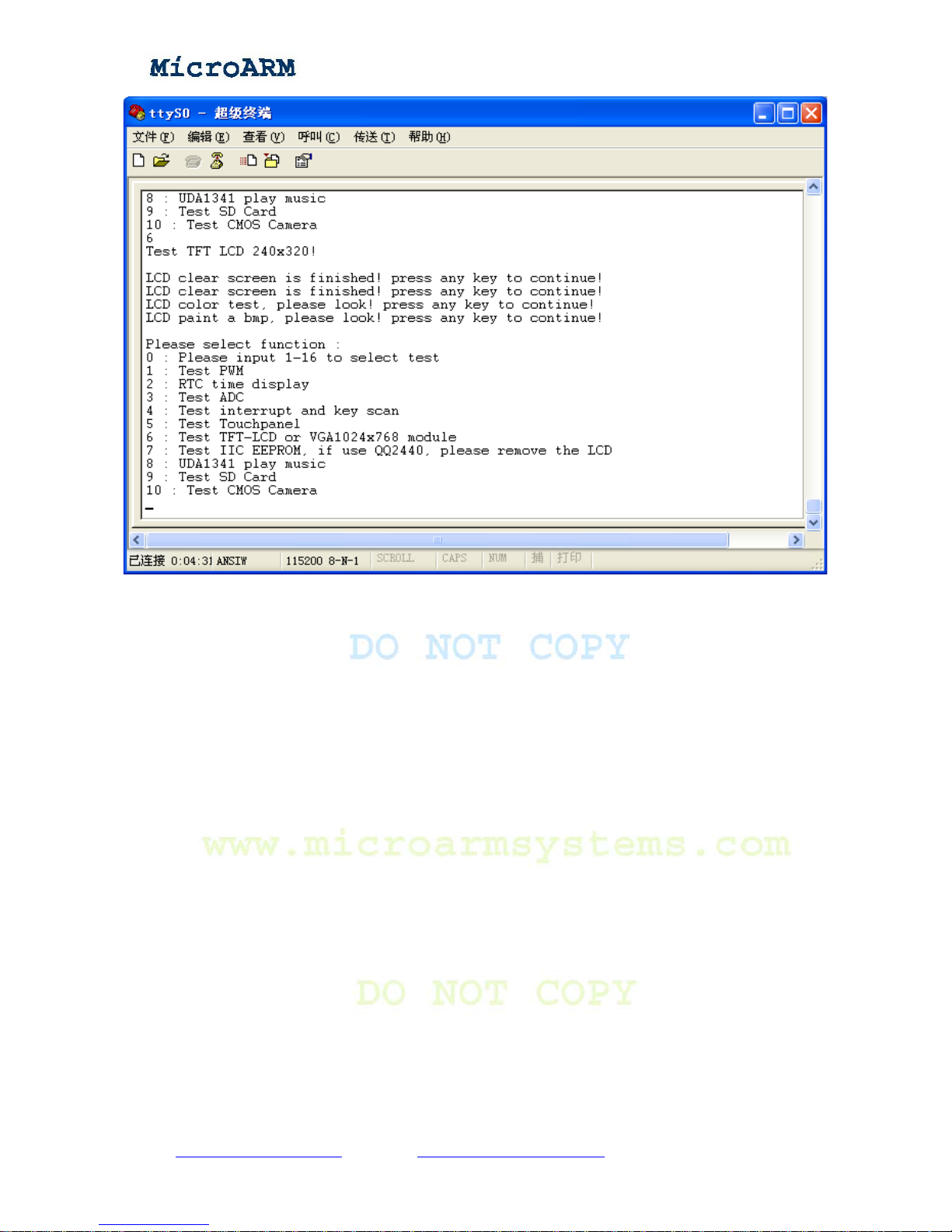
(6) Testing LCD or VGA
Before testing this module, please burn a correct 2440test utility. In the main menu, select “6” and
enter to test. Follow the prompt to press any key you will see LCD show different screen s towards the
last one and return to the main menu.
Copy right reserved © MicroArm Systems, Inc. 1612 2
nd
Ave. SW PMB#108, Cullman, AL 35055 - 44 -
Website : www.microarmsystems.com Email: [email protected] Phone: 1-888-417-9266
Page 45
High Performance Low Cost Embedded Systems
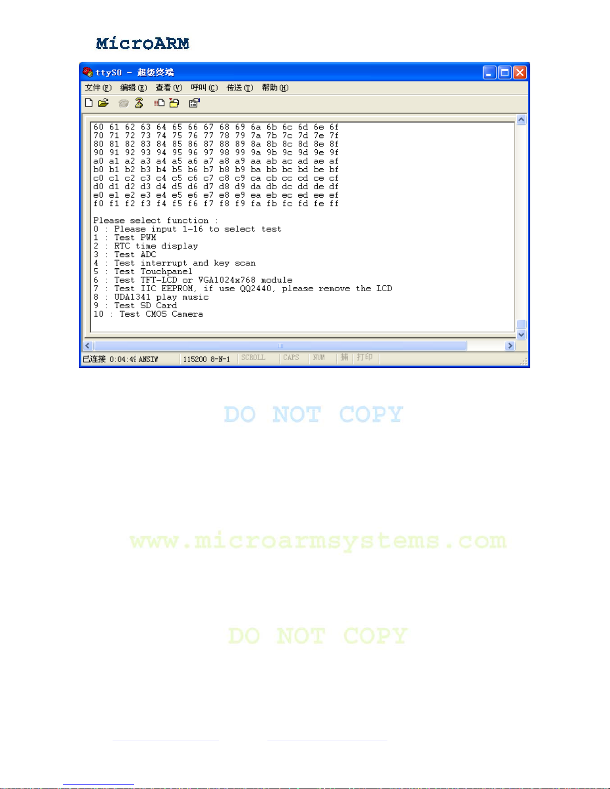
(7) Testing I2C
In the main menu, select “7” and enter to test. The test utility will read from and write to I2C bus
chip AT24C08. The test will write 0x - 0xFF to the chip and read them from it.
Copy right reserved © MicroArm Systems, Inc. 1612 2
nd
Ave. SW PMB#108, Cullman, AL 35055 - 45 -
Website : www.microarmsystems.com Email: [email protected] Phone: 1-888-417-9266
Page 46
High Performance Low Cost Embedded Systems
After this test is done, it will automatically return to the main menu.
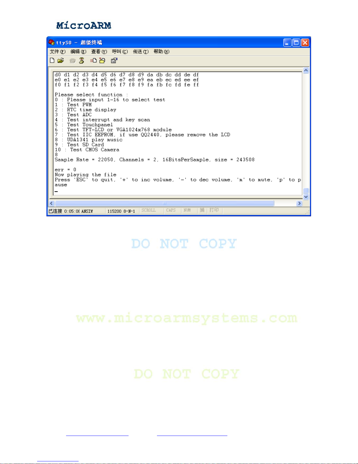
(8) Testing audio output
Connect a sound box to the green audio output port on the MINI2440 board, select “8” in the main
menu and enter, you will hear the Windows XP startup music.
Copy right reserved © MicroArm Systems, Inc. 1612 2
nd
Ave. SW PMB#108, Cullman, AL 35055 - 46 -
Website : www.microarmsystems.com Email: [email protected] Phone: 1-888-417-9266
Page 47
High Performance Low Cost Embedded Systems
Press the “+” or the “-” button to turn up or down the volume. Press the “ESC” key you will exit
the test and return to the main menu.
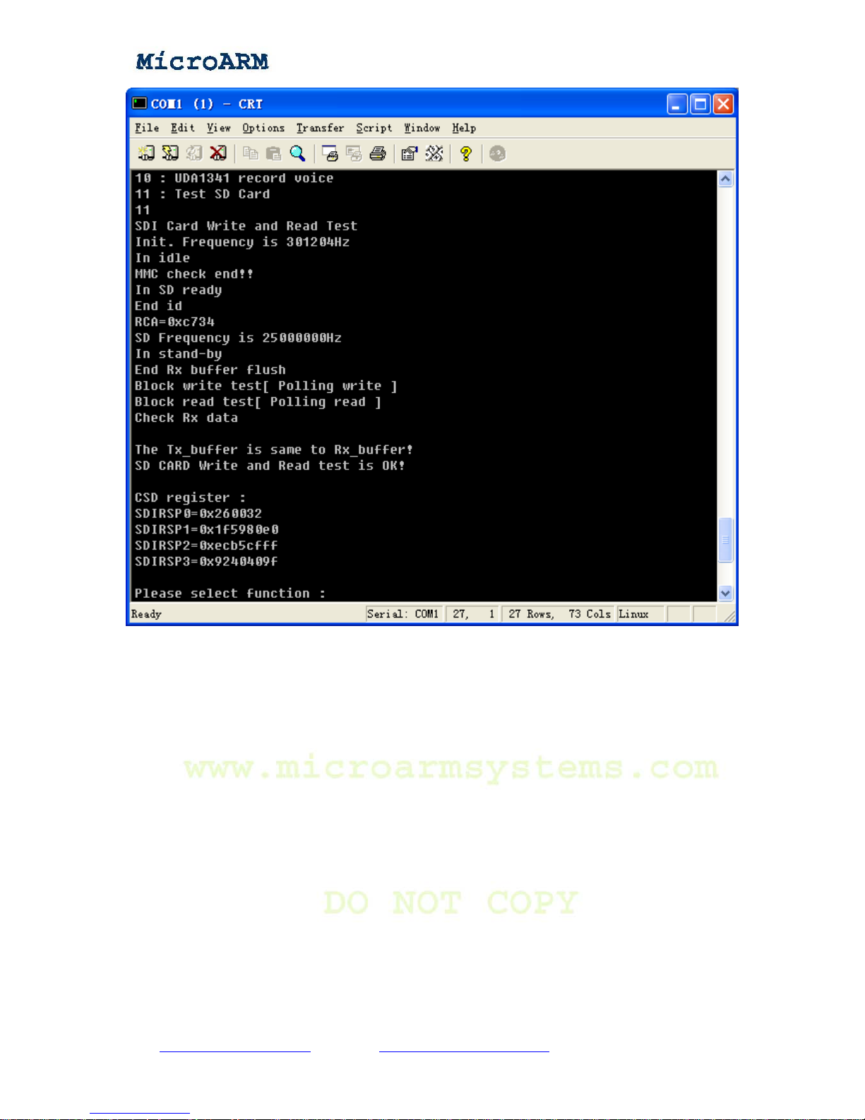
(9) Testing SD card
Note: this test will damage the data in your SD card, before testing please backup your SD data.
Insert your SD card into the SD socket, select “9” in the main menu and enter to test. The test utility
will read from and write to the card, and you will see the following information.
Copy right reserved © MicroArm Systems, Inc. 1612 2
nd
Ave. SW PMB#108, Cullman, AL 35055 - 47 -
Website : www.microarmsystems.com Email: [email protected] Phone: 1-888-417-9266
Page 48
High Performance Low Cost Embedded Systems
These messages show that SD card access is successful. After the test is done it will automatically
return to the main menu.
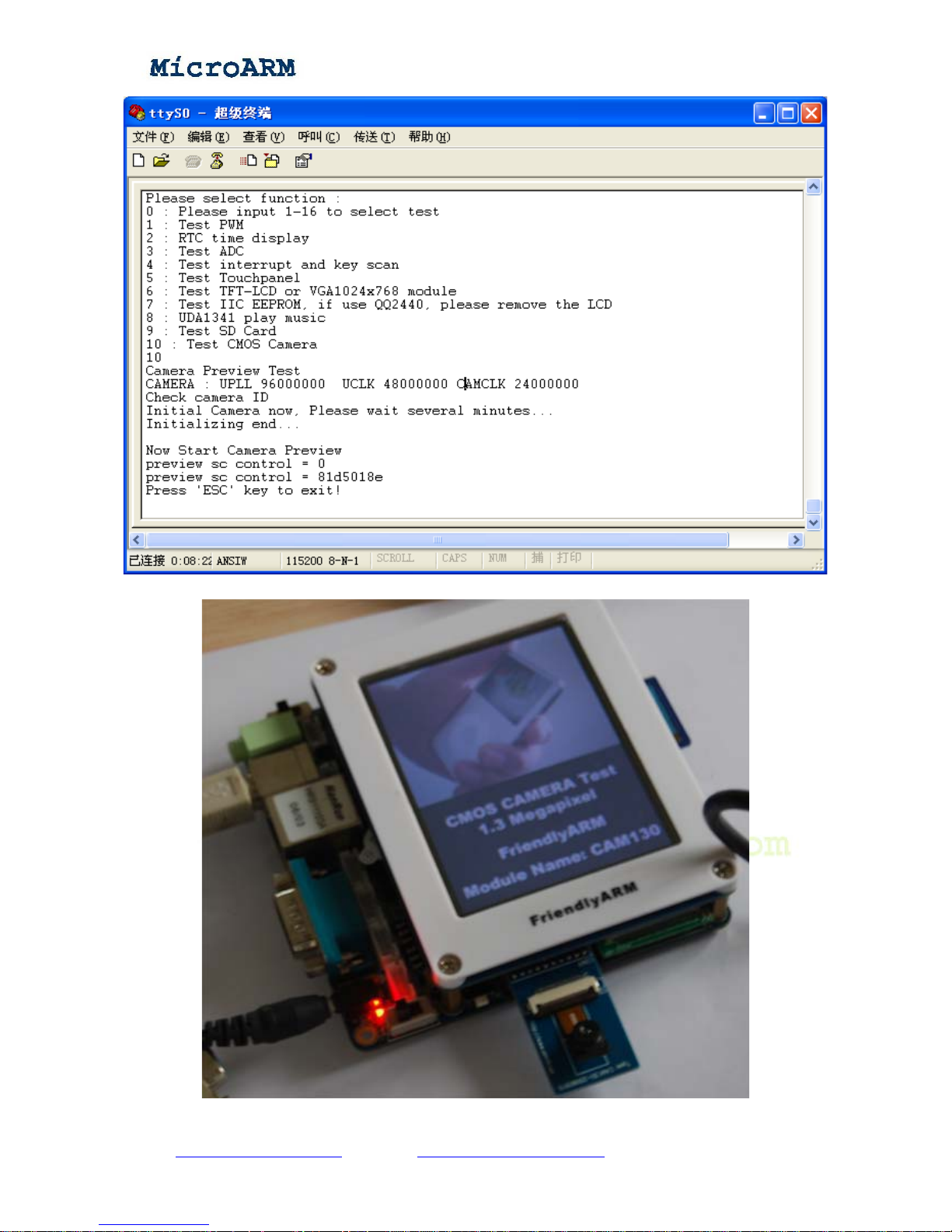
(10) Testing CMOS camera
If you bought a CAM130 CMOS camera from us, you can test it with our utility. Before power on
your board, please connect your camera to the “CAMERA” interface on the board. Then power on the
board, select “10” in the main menu and enter to test.
Note: 如if you use a 7 inch screen or VGA, the LCD display may be different.
Copy right reserved © MicroArm Systems, Inc. 1612 2
nd
Ave. SW PMB#108, Cullman, AL 35055 - 48 -
Website : www.microarmsystems.com Email: [email protected] Phone: 1-888-417-9266
Page 49
High Performance Low Cost Embedded Systems
With a 3.5 inch screen, you will see this:
Copy right reserved © MicroArm Systems, Inc. 1612 2
nd
Ave. SW PMB#108, Cullman, AL 35055 - 49 -
Website : www.microarmsystems.com Email: [email protected] Phone: 1-888-417-9266
Page 50
High Performance Low Cost Embedded Systems
Chapter 3 Running Linux
3.1 Software Applications and Configurations in Linux Qtopia
Note: Qtopia 2.2.0 is developed by Qt based on Qt/Embedded 2.3 graphic interface. After Qtopia
2.2.0, Qt hasn’t released any new PDA versioned graphic interface. The latest Qtopia is for cell
phones. But it is still developing Qt/Embedded libaries. For most of our released systems, we have
installed Linux + Qtopia 2.2.0 by default. It has various useful utilities. When you get our system, just
power it on and you will be able to experience its utilities. If your display is VGA, you need a USB
mouse connected to your board’s USB host.
In addition, our system supports both a USB mouse and a touch screen simultaneously. You can
connect both to your board. It supports a USB mouse and keyboard plug and play.
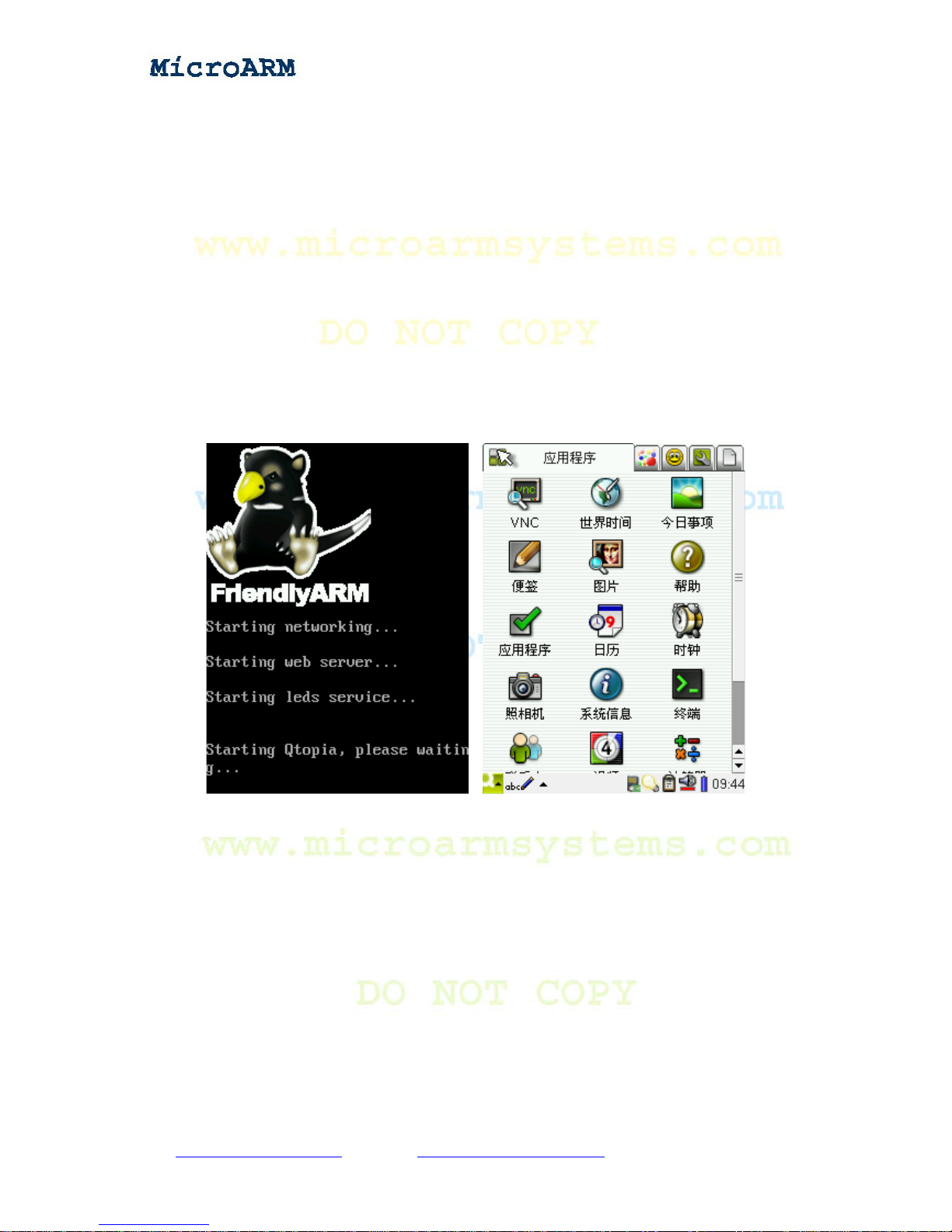
If you use a 3.5 inch LCD, you will see the following screenshot after system boots up:
3.1.1 Calibrating Touch Screen
Note: if you cannot calibrate your screen by following the steps below, please connect a USB
mouse to your board, select “recalibrate” in “setting” to recalibrate your screen.
You will see the calibration interface under the following two situations:
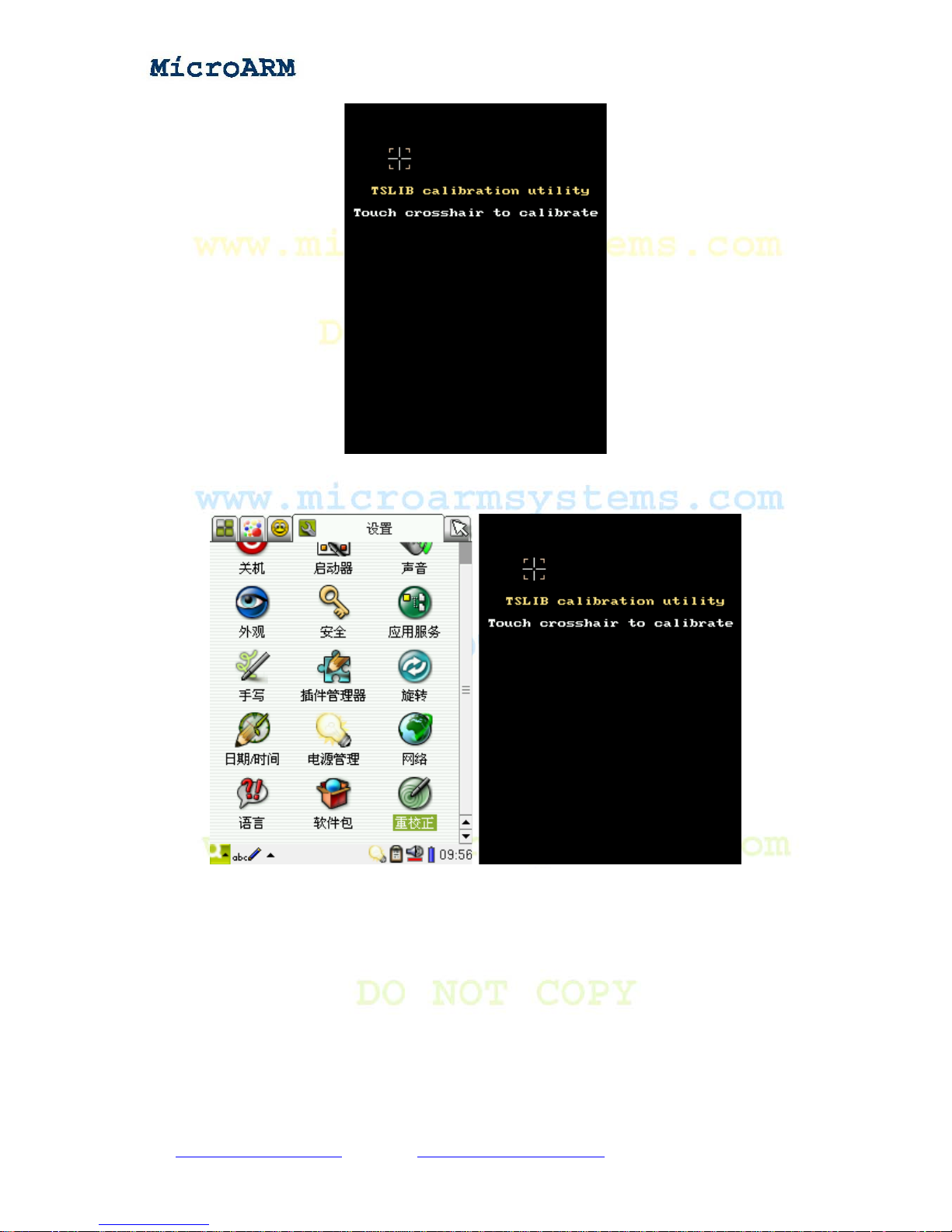
1. After you follow the steps to install the Qtopia system and reboot the system, you will see the
screenshot below . Follow the prompts on the scre en to click on them and then click on the “+” signals.
Copy right reserved © MicroArm Systems, Inc. 1612 2
nd
Ave. SW PMB#108, Cullman, AL 35055 - 50 -
Website : www.microarmsystems.com Email: [email protected] Phone: 1-888-417-9266
Page 51
High Performance Low Cost Embedded Systems
2. After entering the system, go to “Start” -> “Settings” -> “Configurations” -> “Recalibrate”. Click
on the “+” signal.
3.1.2 Main Interface
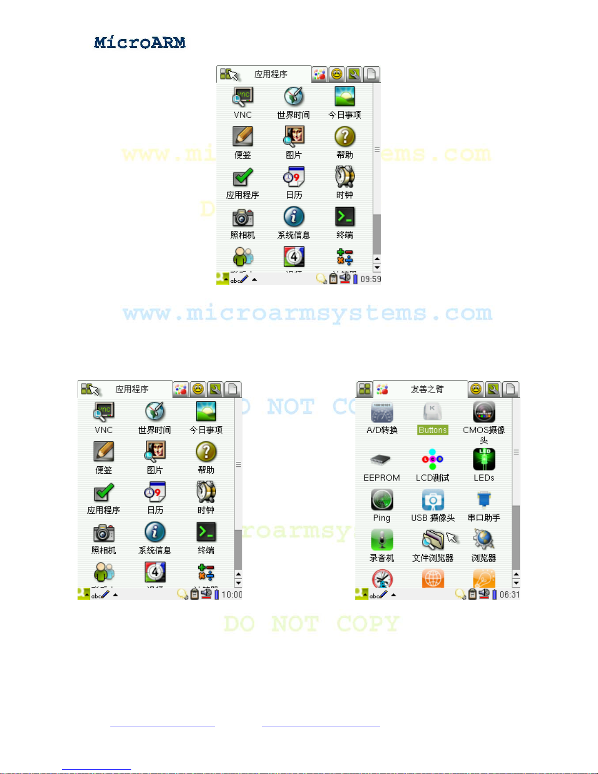
After entering the Qtopia system you will see the following screenshot:
Copy right reserved © MicroArm Systems, Inc. 1612 2
nd
Ave. SW PMB#108, Cullman, AL 35055 - 51 -
Website : www.microarmsystems.com Email: [email protected] Phone: 1-888-417-9266
Page 52
High Performance Low Cost Embedded Systems
On top of the interface, you will see five icons, which represent five types of programs/files. Single
click on anyone you will enter its sub-interface. All of these interfaces are very similar.
In addition, click on the “start” icon on the left bottom of the screen, you will see five sub-menus
too, they are the same as the five ones on the top.
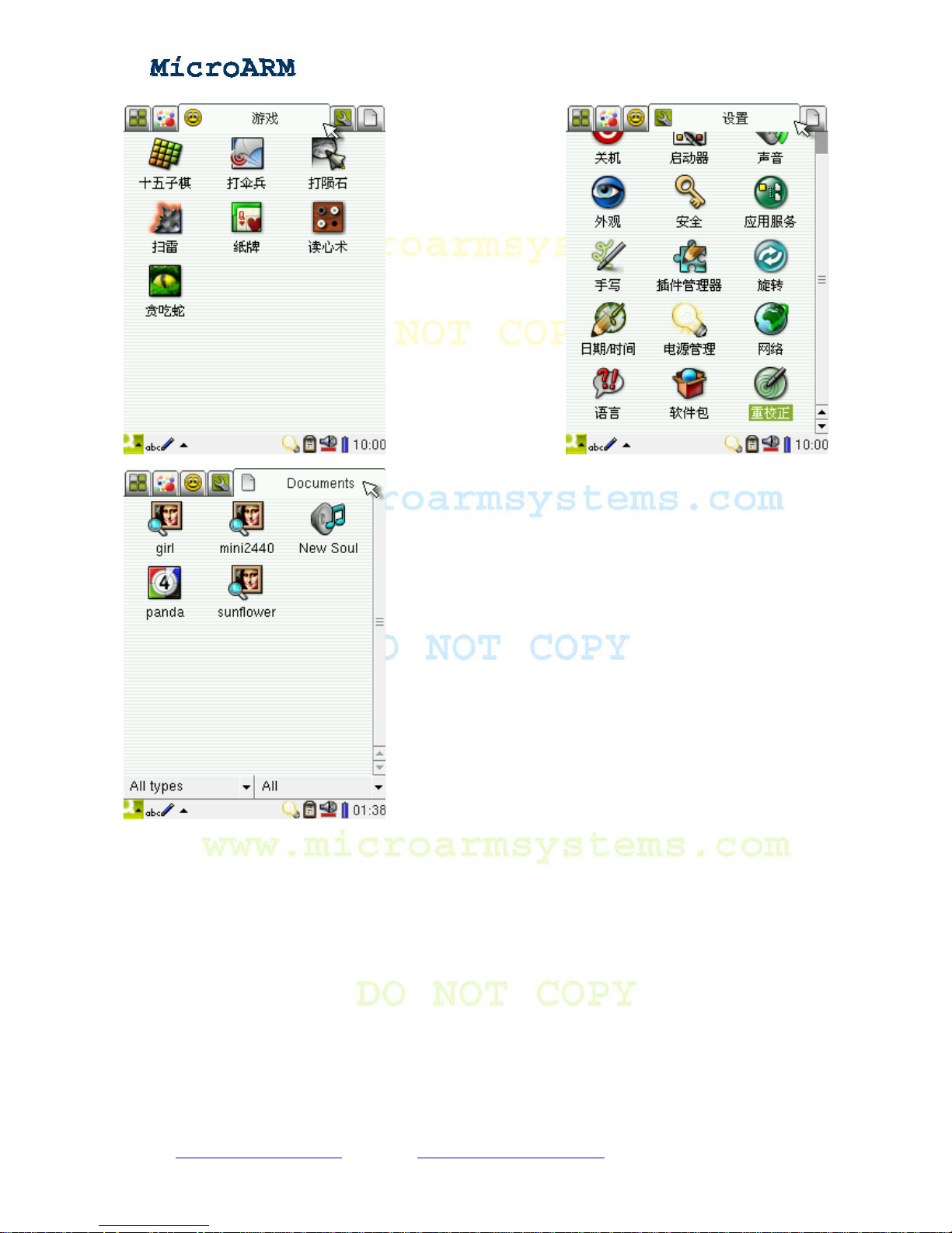
Those five sub-interfaces are as follows:
Copy right reserved © MicroArm Systems, Inc. 1612 2
nd
Ave. SW PMB#108, Cullman, AL 35055 - 52 -
Website : www.microarmsystems.com Email: [email protected] Phone: 1-888-417-9266
Page 53
High Performance Low Cost Embedded Systems
Among those programs, the ones in the “FriendlyA
FriendlyARM. They are only for testing. All the other program
3.1.3 Playing MP3
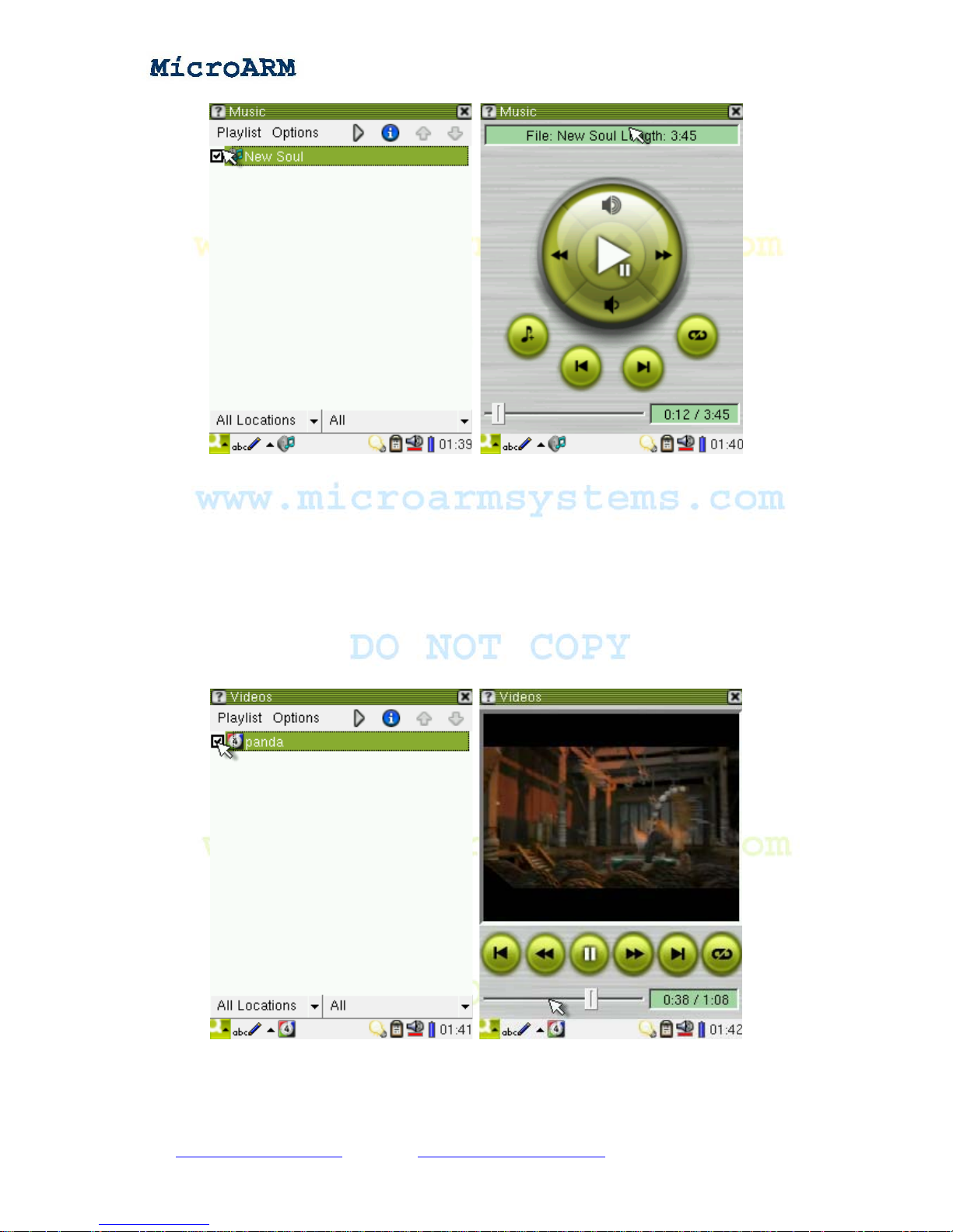
Go to “Application Programs”, click on the “Music” icon, and it will popup a audio player
window. Go to “Audio”, select a mp3 file and click on the “play” button, it will play this MP3 file.
Note: the Audio list lists all the audio files in the “Documents” sub-interface.
Note: you can also click on a file in the “Documents” sub-interface to play it.
RM” sub interface are developed or migrated by
s come with the system.
Copy right reserved © MicroArm Systems, Inc. 1612 2
nd
Ave. SW PMB#108, Cullman, AL 35055 - 53 -
Website : www.microarmsystems.com Email: [email protected] Phone: 1-888-417-9266
Page 54
High Performance Low Cost Embedded Systems
3.1.4 Playing Video
In the “Application Programs” sub-interface, single click on the “video” icon, the video player
interface will popup. Select a file in the “Video” list, and click on the “Play” button to enjoy your
video.
Note: the Video list lists all the video files in the “Documents” sub-interface.
Note: you can also click on a file in the “Documents” sub-interface to play it.
Copy right reserved © MicroArm Systems, Inc. 1612 2
nd
Ave. SW PMB#108, Cullman, AL 35055 - 54 -
Website : www.microarmsystems.com Email: [email protected] Phone: 1-888-417-9266
Page 55
High Performance Low Cost Embedded Systems
3.1.5 Browsing Pictures
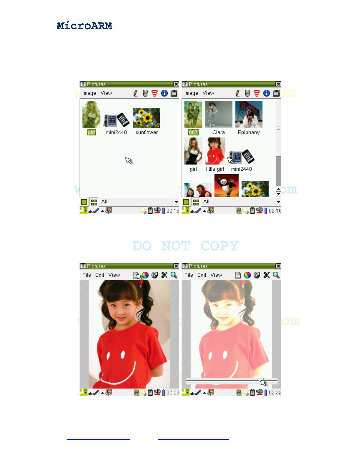
In the sub-interface, single click on the “image” icon to open the image browser. The following
screenshot shows 3 pictures the system has and some other images in an SD card.
In Qtopia 2.2.0, the image browser has more features than the one in Qtopia 1.7.0 such as editing
images.
Editing Images:
Select an image, single click to open it, and click on the pen icon to edit it. Click on the colored
round button in the toolbar to adjust its color:
Rotating Images
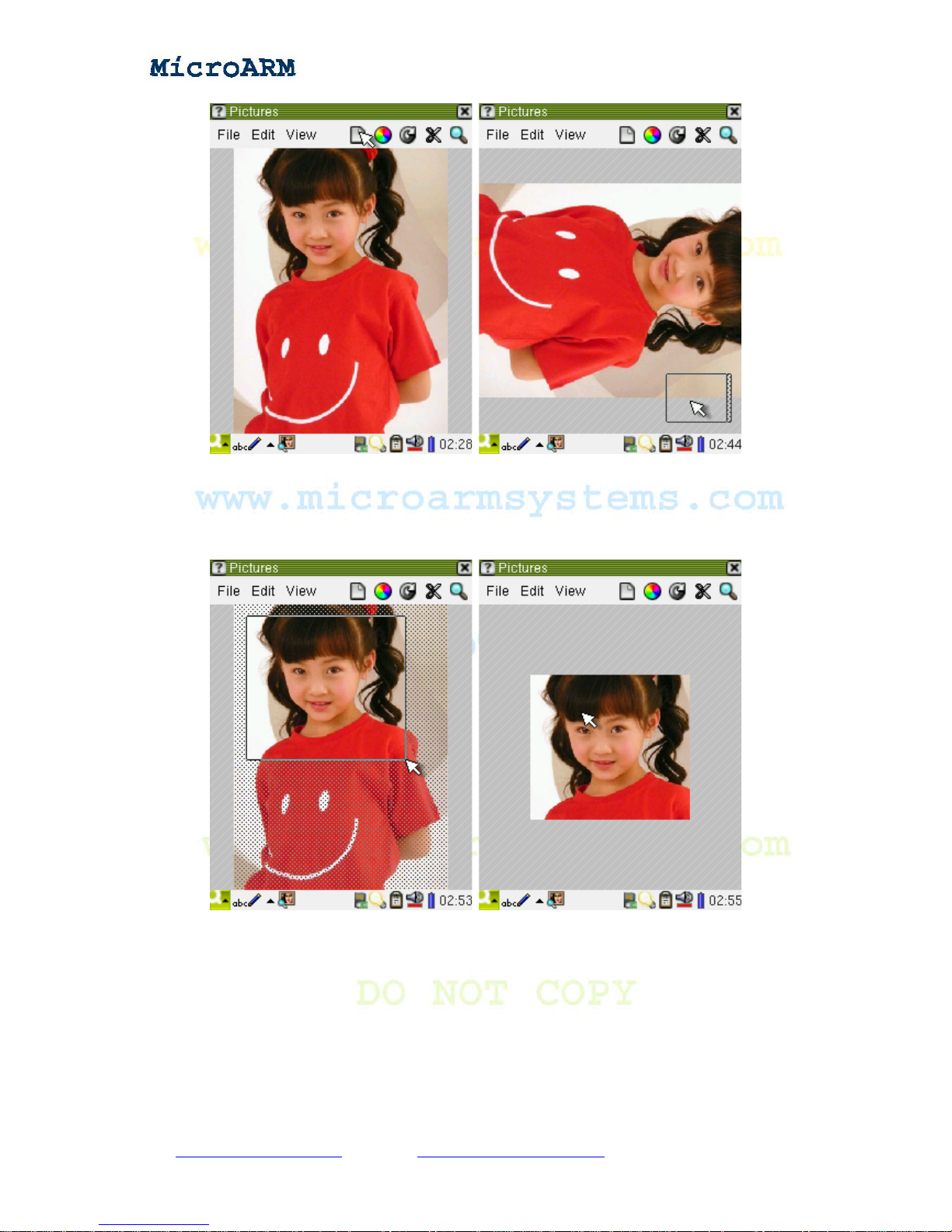
In the toolbar, click on the clockwise button you can rotate the image by 90 degrees
Copy right reserved © MicroArm Systems, Inc. 1612 2
nd
Ave. SW PMB#108, Cullman, AL 35055 - 55 -
Website : www.microarmsystems.com Email: [email protected] Phone: 1-888-417-9266
Page 56
High Performance Low Cost Embedded Systems
Cutting Images:
In the edit mode, click on the “scissors” button, the image will be shaded. Select an area with in the
image with a touch pen, release the pen, the selected area will be isolated and then you can edit this
area.
Zooming In/Out Images:
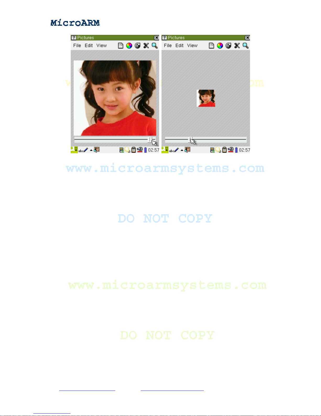
In the edit mode, click on the magnifier icon, you will be able to zoom in or out an image.
Copy right reserved © MicroArm Systems, Inc. 1612 2
nd
Ave. SW PMB#108, Cullman, AL 35055 - 56 -
Website : www.microarmsystems.com Email: [email protected] Phone: 1-888-417-9266
Page 57
High Performance Low Cost Embedded Systems
Note: the picture browser lists all the files in the “Documents” sub-interface.
Note: you can also click on a file in the “Documents” sub-interface to open it.
3.1.6 Auto Mounting SD and USB Drives
As long as your system is active, inserting a SD card (maximum of 32G) or USB portable storage,
moments later a removable device icon will appear on the right bottom of the task bar. Our system
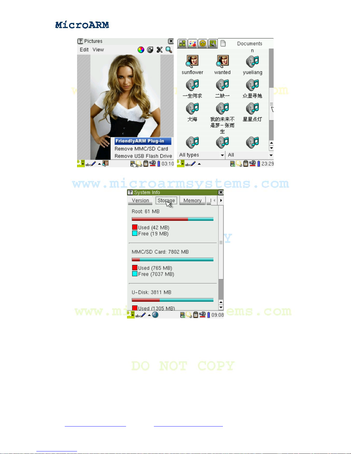
supports mounting both cards simultaneously. Click on the removable device icon, you will see the
screenshot below . Then you will be able to remove it safely like what you do in W indows. The files in
the plugged MMC/SD card will be listed in the “Documents” group.
Note: the support for MMC/SD cards and auto mounting is implemented via a Qtopia 2.2.0 plugin
developed by FriendlyARM. Now it can only recognize the first partition of a MMC/SD card whose
file format should be VFAT/FAT32/FAT16. If you card cannot be recognized, please check whether
the file system is VFAT/FAT32/FAT16.
Copy right reserved © MicroArm Systems, Inc. 1612 2
nd
Ave. SW PMB#108, Cullman, AL 35055 - 57 -
Website : www.microarmsystems.com Email: [email protected] Phone: 1-888-417-9266
Page 58
High Performance Low Cost Embedded Systems
Go to “Application Programs” -> “System Info” -> “Storage”, you will be able to see more details
about the SD or USB drive.
3.1.7 Calculator
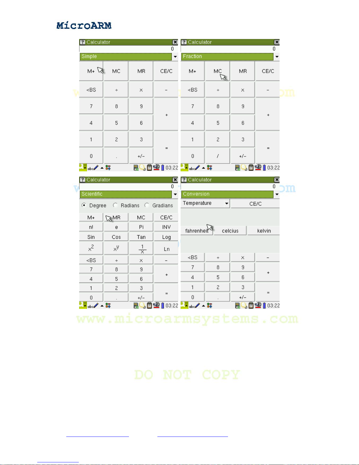
In the sub-interface “Application Programs”, click on the calculator icon you will see a calculator.
You can choose its type by selecting dif ferent options (Simple, Fraction, Scientific, Conversion and
so on) from the pull-down list.
Copy right reserved © MicroArm Systems, Inc. 1612 2
nd
Ave. SW PMB#108, Cullman, AL 35055 - 58 -
Website : www.microarmsystems.com Email: [email protected] Phone: 1-888-417-9266
Page 59
High Performance Low Cost Embedded Systems
3.1.8 Command Line
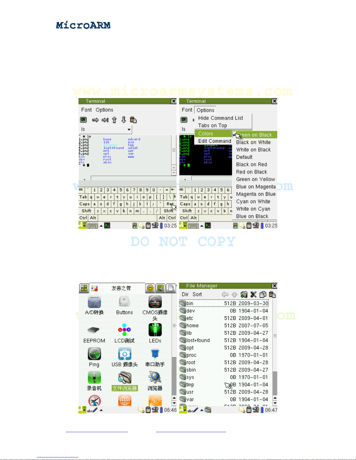
The “terminal” is a commonly used interface in Linux. Users can command the system very
easily via a command line window. There are various ways to open a terminal. For instance, you
can set the system’s terminal to a serial port then this terminal will be a serial port terminal whose
input and output are both through the serial port terminal without relying on a graphic interface.
This is the most popular way in Linux.
On system startup, you can point the terminal to a graphic display device (such as LCD, CRT) and
the input to the keyboard. This will create another input output system without using a PC.
Copy right reserved © MicroArm Systems, Inc. 1612 2
nd
Ave. SW PMB#108, Cullman, AL 35055 - 59 -
Website : www.microarmsystems.com Email: [email protected] Phone: 1-888-417-9266
Page 60
High Performance Low Cost Embedded Systems
When a graphic display interface is connected and a GUI is incorporated, a GUI based “command
window” will be established. Users can interact with the system via either a real keyboard or a virtual
“soft keyboard”. This is what this section describes.
In the “Application Programs” subgroup, click on the “terminal” icon, a command line window will
popup. You can either connect a USB keyboard (connect it after starting this command line window)
to your system or use the keyboard window at the bottom of the screen. You can set the command line
window’s display mode by configuring the settings in the “option” menu.
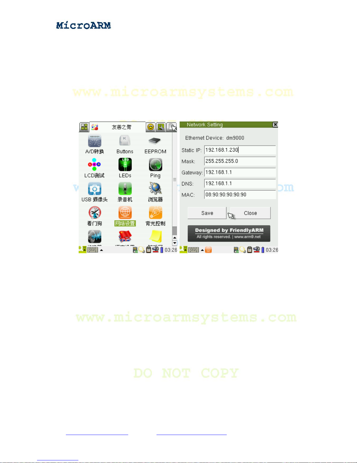
3.1.9 File Browser
In the “FriendlyARM” group click on the file browser icon:
Copy right reserved © MicroArm Systems, Inc. 1612 2
nd
Ave. SW PMB#108, Cullman, AL 35055 - 60 -
Website : www.microarmsystems.com
Email: [email protected] Phone: 1-888-417-9266
Page 61
High Performance Low Cost Embedded Systems
You can browse the directories and files in the system via this browser.
Note: Qtopia-2.2.0 doesn’t have a file browser, FriendlyARM migrated one from Qtopia-1.7.0.
They have the same functions and interface.
3.1.10 Configuring Network
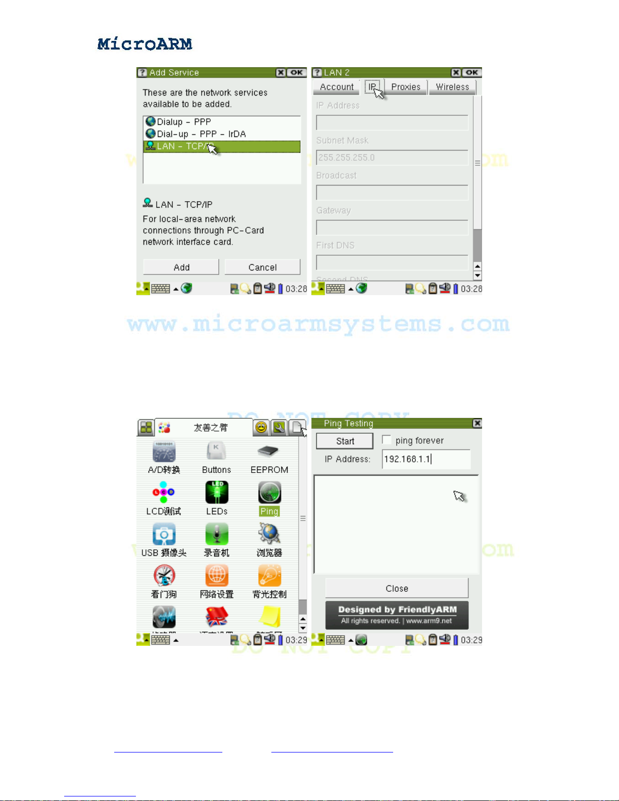
In the “FriendlyARM” subgroup, click on the “Network Settings” icon:
From this interface we can set various network parameters:
- Static IP address, default setting is 192.168.1.230
- Mask, default setting is 255.255.255.0
- Gateway, default setting is 192.168.1.1
- DNS, default setting is 192.168.1.1
- MAC address, default setting is 08:90:90:90:90:90
Click on “Save” to save these parameters and they are effective right now. After rebooting the
system, these settings will still be there. The configuration file that contains the settings is
“/etc/eth0-setting”.
Note: the “/etc/eth0-setting” file will not exist after reinstalling the system. Clicking on the “Save”
button will generate one. Because all products are tested extensively by us, this file exists in your
system. Executing the “ifconfig” command will not change this file. In fact, Qtopia has a network
setting utility by itself. But its interface is too complicated and may not work sometimes. We didn’t
make any change to this utility however created another one shown above.
The one Qtopia has is as follows:
Copy right reserved © MicroArm Systems, Inc. 1612 2
nd
Ave. SW PMB#108, Cullman, AL 35055 - 61 -
Website : www.microarmsystems.com Email: [email protected] Phone: 1-888-417-9266
Page 62
High Performance Low Cost Embedded Systems
3.1.11 Testing Ping
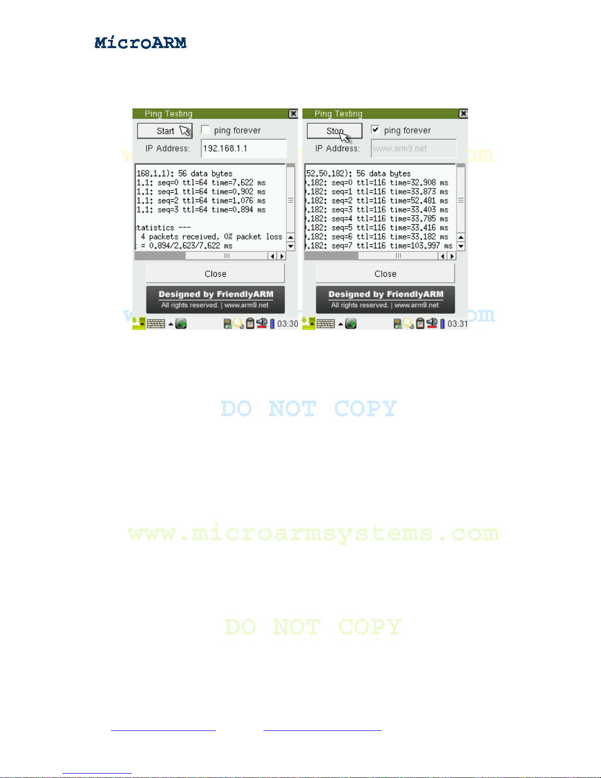
Please connect your board to a network, set up the network parameters such as gateway, DNS and
so on. Then you can use our graphic interface to test network connection. In the “FriendlyARM”
subgroup, click on the “Ping” utility:
After you setup your DNS, your system will be able to recognize both character domain names and
IP addresses. By default, ping will try four times. But if you check the “p ing forever” option, it will
ping forever.
Copy right reserved © MicroArm Systems, Inc. 1612 2
nd
Ave. SW PMB#108, Cullman, AL 35055 - 62 -
Website : www.microarmsystems.com Email: [email protected] Phone: 1-888-417-9266
Page 63
High Performance Low Cost Embedded Systems
Note: To ping an internet domain name, you need to set up your gateway and DNS correctly and
make sure your systems is connected to the internet.
Clicking on “Start” to ping, and “Stop” to end it. Before closing the interface you need to stop ping .
Note: ping is a commonly used network utility , and it is in most of the released Linux and W indows
systems. In a command line window , typing “ping” will start it. The above utility actually calls “ping”
in a command line and shows the results in the graphic interface.
3.1.12 Browser
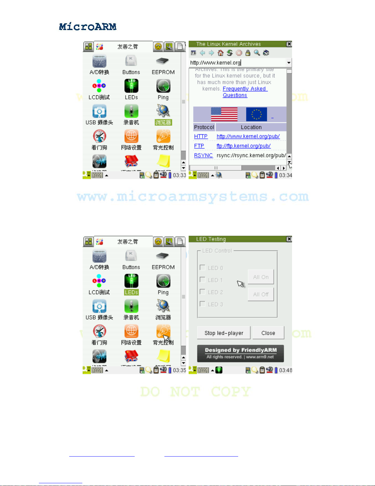
In the “FriendlyARM” subgroup, click on the “browser” icon to open a browser, trigger the soft
keyboard at the bottom of the screen, enter a website in the address bar, hit enter to open the
website.
Note: the web browser this system uses is Konqueror/Embedded” which is an open source
browser.
Copy right reserved © MicroArm Systems, Inc. 1612 2
nd
Ave. SW PMB#108, Cullman, AL 35055 - 63 -
Website : www.microarmsystems.com Email: [email protected] Phone: 1-888-417-9266
Page 64
High Performance Low Cost Embedded Systems
3.1.13 Testing LED
In the “FriendlyARM” subgroup, click on the “LED” icon:
On the popup window, the “Stop led-player” is enabled. This is because the led-player service is
started on system startup. After the sy stem boots up, you will see a “sequen tial led lighting” which is
played by this service. To control a single LED, close this service to release the LED resources.
Follow the steps below:
Click on the “Stop led-player” button, its title will change to “S tart led-player”, all the LEDs on the
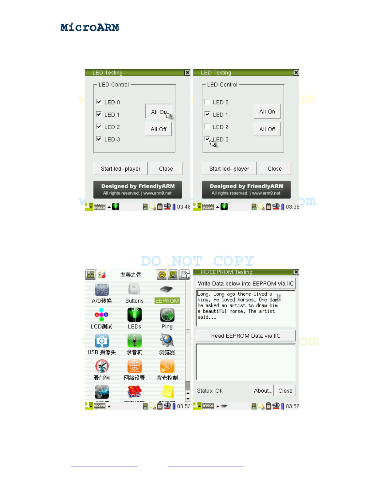
board will be turned off, and all the buttons in th e “LED Control” frame will be enabled. Clicking on
Copy right reserved © MicroArm Systems, Inc. 1612 2
nd
Ave. SW PMB#108, Cullman, AL 35055 - 64 -
Website : www.microarmsystems.com Email: [email protected] Phone: 1-888-417-9266
Page 65
High Performance Low Cost Embedded Systems
the “All On” button will turn on all the LEDs, and clicking on the “All Off” will turn of f all the LEDs.
Checking any LED box will turn on that LED, and unchecking will turn it off. Close the LED Testing
interface the led-player service will be restarted.
3.1.14 Testing EEPROM
In the “FriendlyARM” subgroup, click on the “I2C-EEPROM” icon to open the interface below:
From top to bottom there are a “Write Data” button, Write area, “Read Data” button and read area.
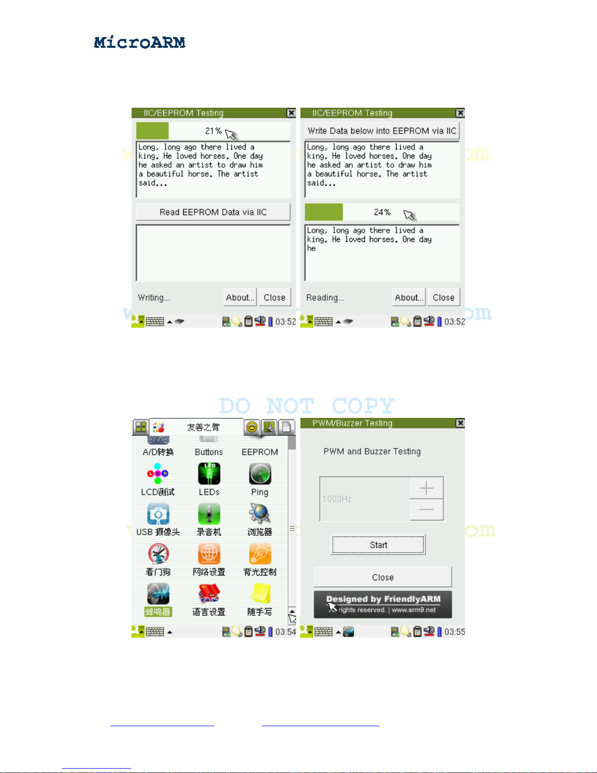
Click on the soft keyboard icon in the task bar, write some characters in the write area, click on the
Copy right reserved © MicroArm Systems, Inc. 1612 2
nd
Ave. SW PMB#108, Cullman, AL 35055 - 65 -
Website : www.microarmsystems.com Email: [email protected] Phone: 1-888-417-9266
Page 66
High Performance Low Cost Embedded Systems
“Write Data” button, the button will change to a process bar indicating the writing process; click on
the “Read Data” button, it will change to a process bar too indicating the reading process.
3.1.15 PWM Buzzer
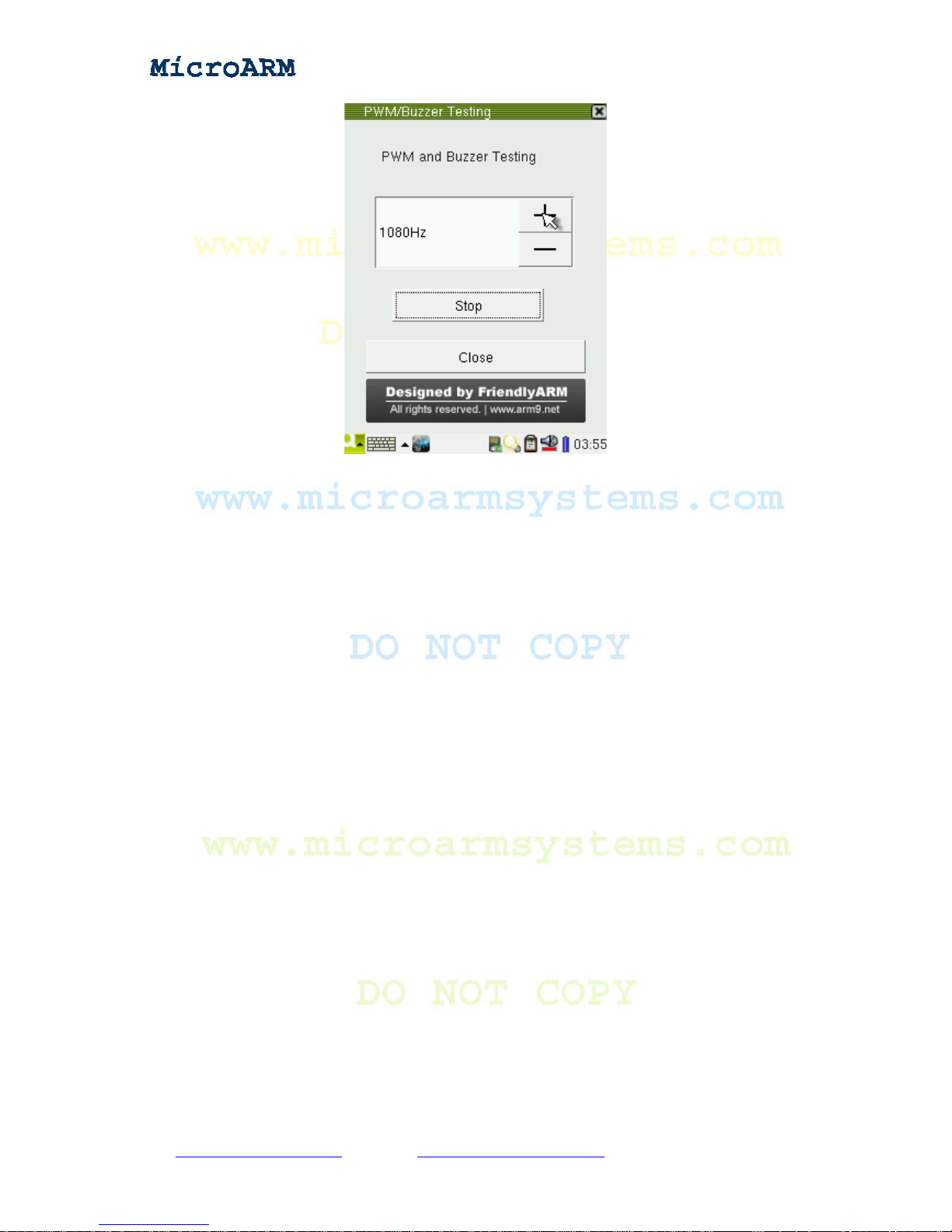
In the “FriendlyARM” subgroup, click on the “PWM/Buzzer Testing” icon:
By default, the output frequency of PWM is 1000Hz. Click on the “Start” button, the buzzer will
beep. Clicking on the “+” or “-” button will change its frequency and sound as well. Clicking on the
“Stop” button stops the buzzer.
Copy right reserved © MicroArm Systems, Inc. 1612 2
nd
Ave. SW PMB#108, Cullman, AL 35055 - 66 -
Website : www.microarmsystems.com Email: [email protected] Phone: 1-888-417-9266
Page 67
High Performance Low Cost Embedded Systems
3.1.16 Serial Port Assistant
Note: before start this program please connect the serial port your want to test to your board.
- The on board CON1, 2 and 3 are CPU UART0, 1 and 2. UART0 has been converted to
RS232, and extended to COM0 via DB9. On system startup it has been set to the console terminal, so
it cannot be tested via this utility . The other two ports CON2 and 3 must be converted to RS232 before
they can communicate with a PC serial port. (FriendlyARM has a “OneCom” RS232 conversion
module) When connect the ports to a PC, please make sure to use a correct serial cable (cross serial
line or direct serial line). When connect the OneCom module’s COM2 and COM3 make sure they
match your cable
- This program also supports common USB to Serial cables. Now most laptops don’t have serial ports.
For the sake of users most of our agents provide those conversion cables. Connecting a USB to Serial
cable to your board, you can extend your serial ports. Its device name generally is “/dev/ttyUSB0, 1,
2 and 3”, which implies you can use a USB hub to extend your serial ports.
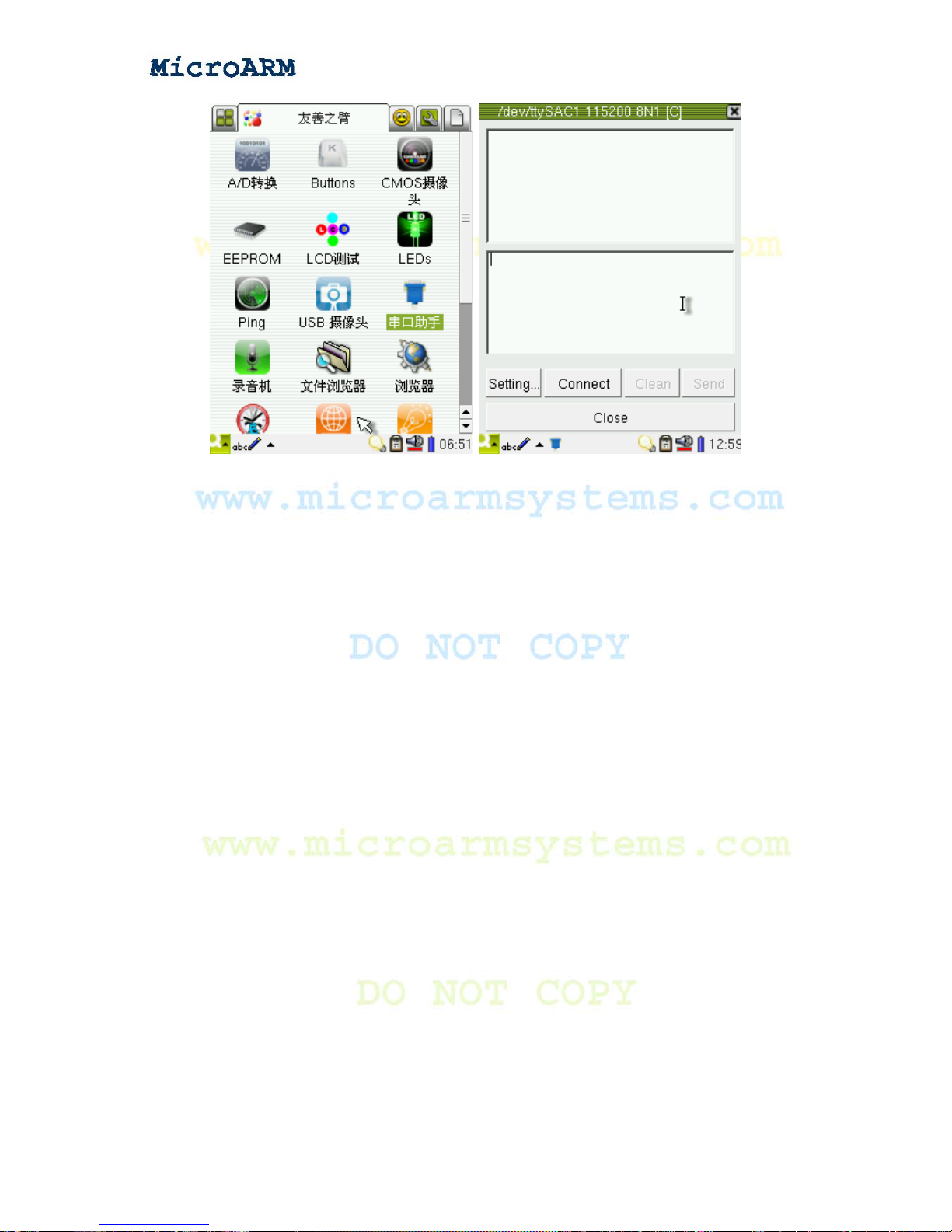
In the “FriendlyARM” subgroup, click on the “Serial Port Assistant” icon to start the interface
below:
Copy right reserved © MicroArm Systems, Inc. 1612 2
nd
Ave. SW PMB#108, Cullman, AL 35055 - 67 -
Website : www.microarmsystems.com Email: [email protected] Phone: 1-888-417-9266
Page 68
High Performance Low Cost Embedded Systems
The title bar of the utility shows the default setting is “ttySAC1 115200 8N1 [C]”, and it implies the
default port is:
- Serial Port Deivce: /dev/ttySAC1, it corresponds to the second port UART1
- Bits Per Second: 115200
- Data Bits: 8
- Flow Control: None
- Stop Bits: 1
- [C]: stands for the character mode; [H] stands for Hex
There are two edit areas in the interface, the top one shows received data which cannot be edited;
the bottom one shows sent data which can be edited via a USB keyboard or a soft keyboard.
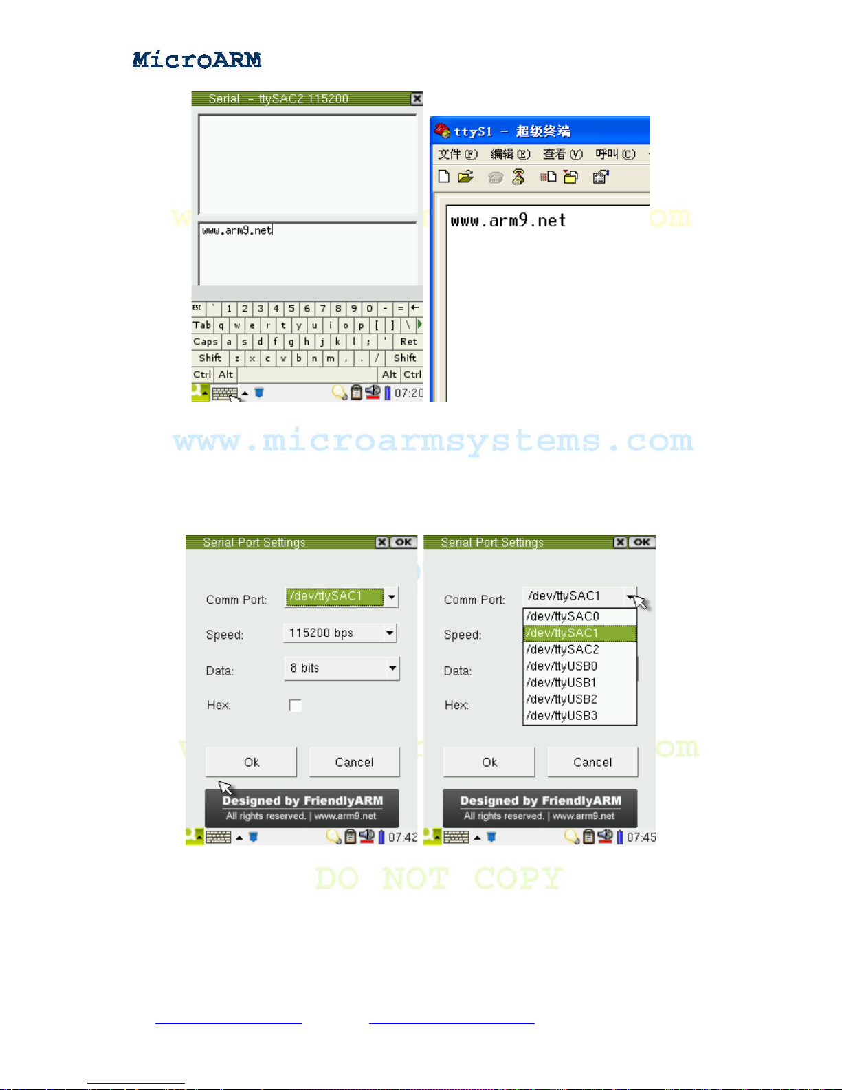
Click on the “Connect” button to open “/dev/ttySAC1”, type some characters in the edit area, click
on the “Send” button and it will send data to the connected serial port device. The screenshot below
shows what a Windows super terminal receives (Note: the settings for this super terminal should be
115200 8N1)
Copy right reserved © MicroArm Systems, Inc. 1612 2
nd
Ave. SW PMB#108, Cullman, AL 35055 - 68 -
Website : www.microarmsystems.com Email: [email protected] Phone: 1-888-417-9266
Page 69
High Performance Low Cost Embedded Systems
Click on “Disconnect” to disconnect the connection. Click on “Setting…” to enter the parameter
setting interface which lists some basic serial port parameters:
Comm Port: you can choose “/dev/ttySAC0,1,2” or the USB to Serial “/dev/ttyUSB0,1,2,3”
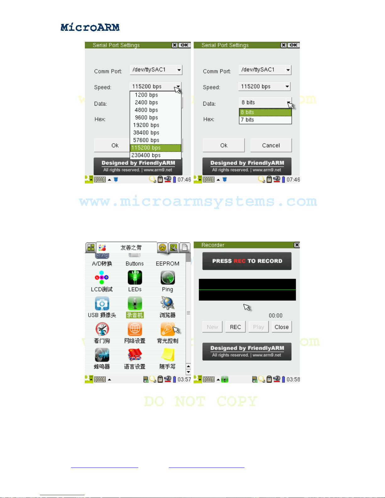
Speed: bits per second
Data: data bits, 8 or 7, usually 8.
Hex: input and output data in Hex format
Copy right reserved © MicroArm Systems, Inc. 1612 2
nd
Ave. SW PMB#108, Cullman, AL 35055 - 69 -
Website : www.microarmsystems.com Email: [email protected] Phone: 1-888-417-9266
Page 70
High Performance Low Cost Embedded Systems
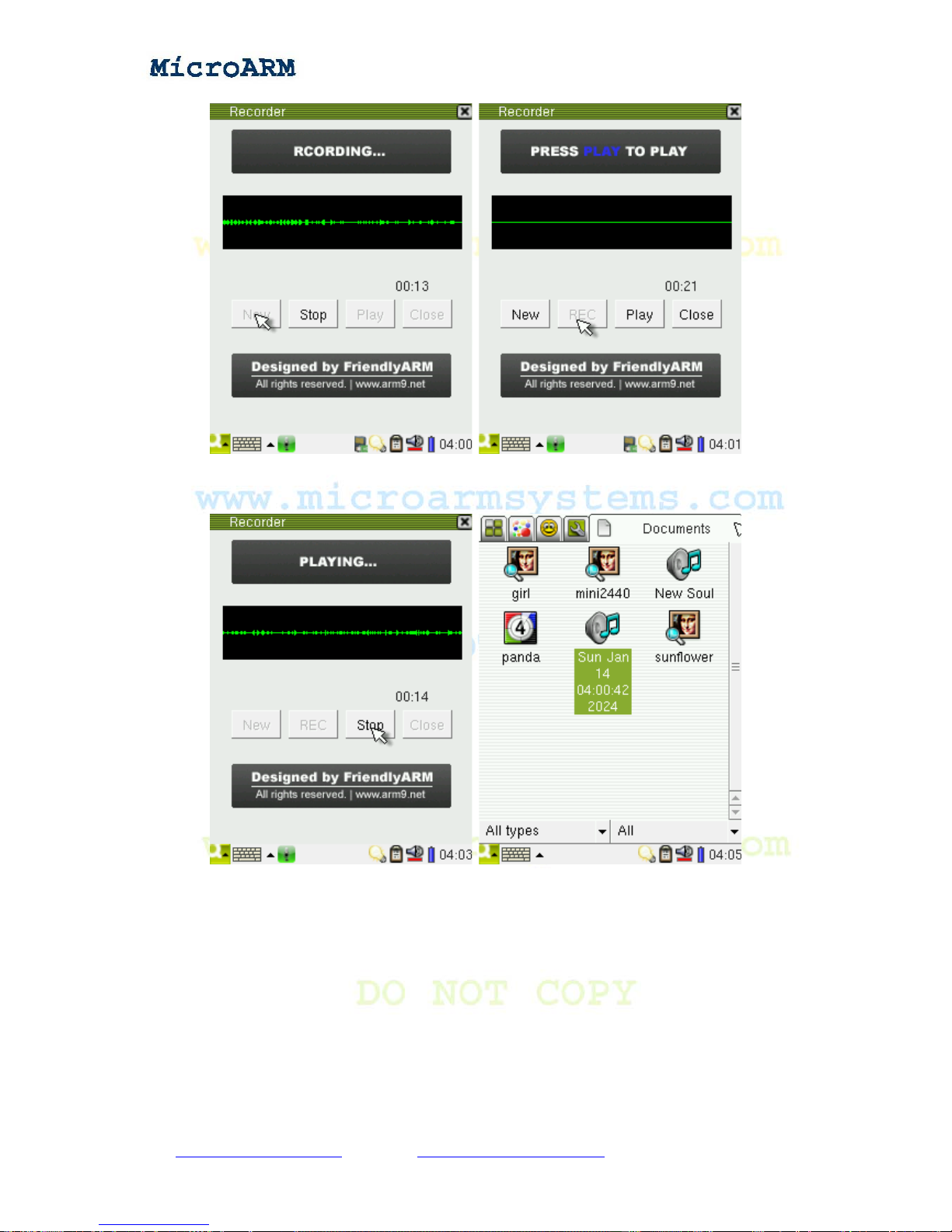
3.1.17 Audio Recording
In the “FriendlyARM” subgroup, click on the “recorder” icon:
Click on the “REC” button to start recording. When you speak to the microphone on the board, you
will see audio waves shown on the screen. Click on the “STOP” button to stop recording.
Copy right reserved © MicroArm Systems, Inc. 1612 2
nd
Ave. SW PMB#108, Cullman, AL 35055 - 70 -
Website : www.microarmsystems.com Email: [email protected] Phone: 1-888-417-9266
Page 71
High Performance Low Cost Embedded Systems
Click on the “PLA Y” button to play what you recorded and you can see what you recorded has been
saved as “WAV” files in the “Documents” directory.
Note: Qtopia 2.2.0 has a recorder utility by itself. But it cannot record audio. We leave it as what it
is.
3.1.18 Using USB Camera
You can use any USB camera with our system which already has drivers for all existing USB
cameras. Plug your camera to the USB host port on the board, click on the “USB Camera” in the
“FriendlyARM” subgroup you will see a dynamic preview interface. Click on the “Snap” button you
Copy right reserved © MicroArm Systems, Inc. 1612 2
nd
Ave. SW PMB#108, Cullman, AL 35055 - 71 -
Website : www.microarmsystems.com Email: [email protected] Phone: 1-888-417-9266
Page 72
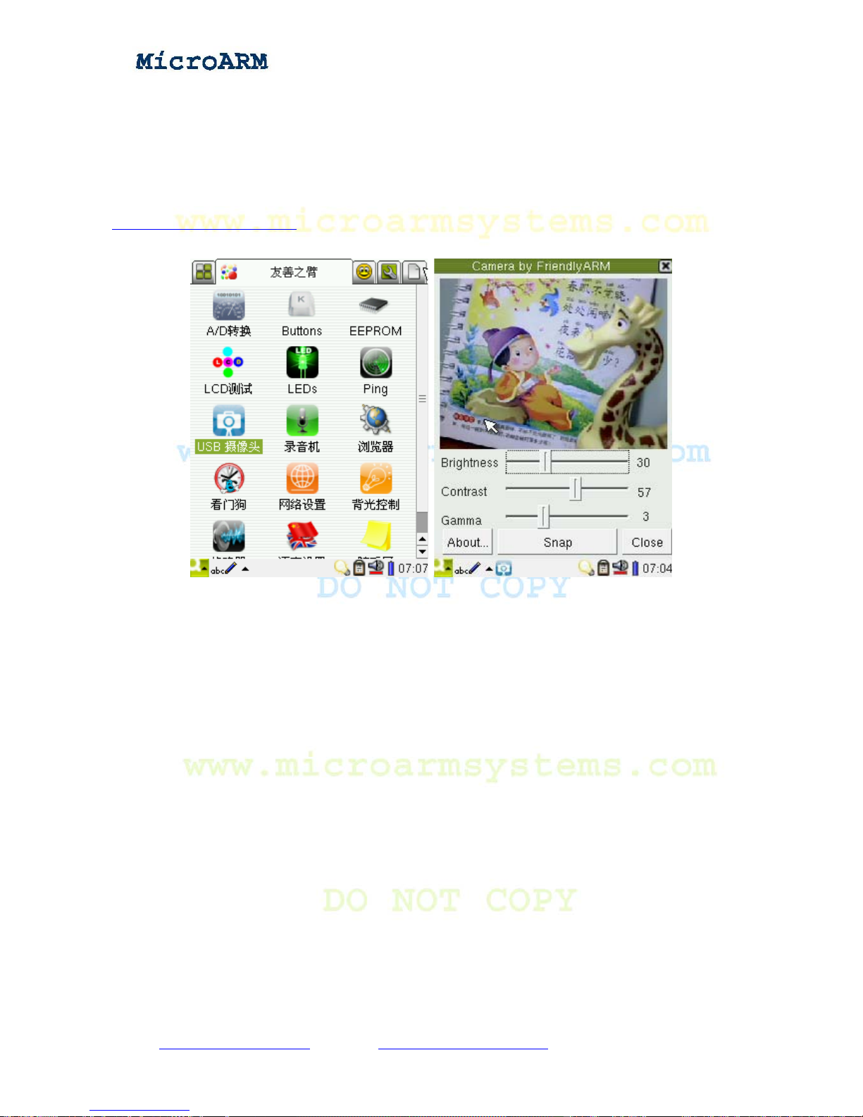
High Performance Low Cost Embedded Systems
will take a picture which will be saved in the “Documents”. This utility has provides functions to
adjust brightness, contrast and gamma value. When you start this utility , it w ill read the camera preset
parameters.
Note: although the system already has drivers for USB cameras, each camera might have different
output format. Since we cannot collect all cameras this utility would only work for some common
cameras, if your camera doesn’t work with our system please email us at
3.1.19 Using CMOS Camera
This utility can only work with the CMOS camera CAM130. Before power on, please connect
your camera to the “CAMERA” interface on the board, and then click on the “CMOS Camera” icon
in the “FriendlyARM” subgroup.
Copy right reserved © MicroArm Systems, Inc. 1612 2
nd
Ave. SW PMB#108, Cullman, AL 35055 - 72 -
Website : www.microarmsystems.com Email: [email protected] Phone: 1-888-417-9266
Page 73
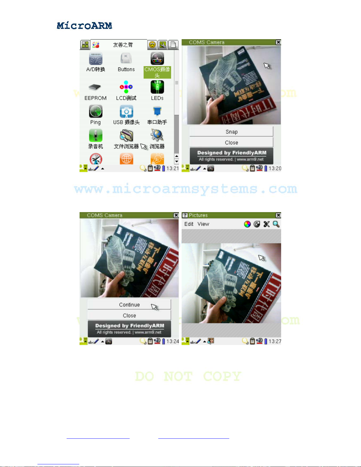
High Performance Low Cost Embedded Systems
Click on the “Snap” button you will be able to take a picture which will be saved in the
“Documents” subgroup (in the “/root/Documents/image/jpeg” directory). Then the “Snap” button
will change to “Continue”. Click on it, you will be ready for picture taking again. When clicking on a
taken picture in the “Documents” subgroup, it will be opened with Qtopia’s picture browser utility.
3.1.20 Testing LCD
The LCD test utility is to test whether a LCD has dead pixels. We can only allow at most 3 dead
pixels for our systems. In the “FriendlyARM” subgroup, click on the “LCD Testing” icon:
Copy right reserved © MicroArm Systems, Inc. 1612 2
nd
Ave. SW PMB#108, Cullman, AL 35055 - 73 -
Website : www.microarmsystems.com Email: [email protected] Phone: 1-888-417-9266
Page 74
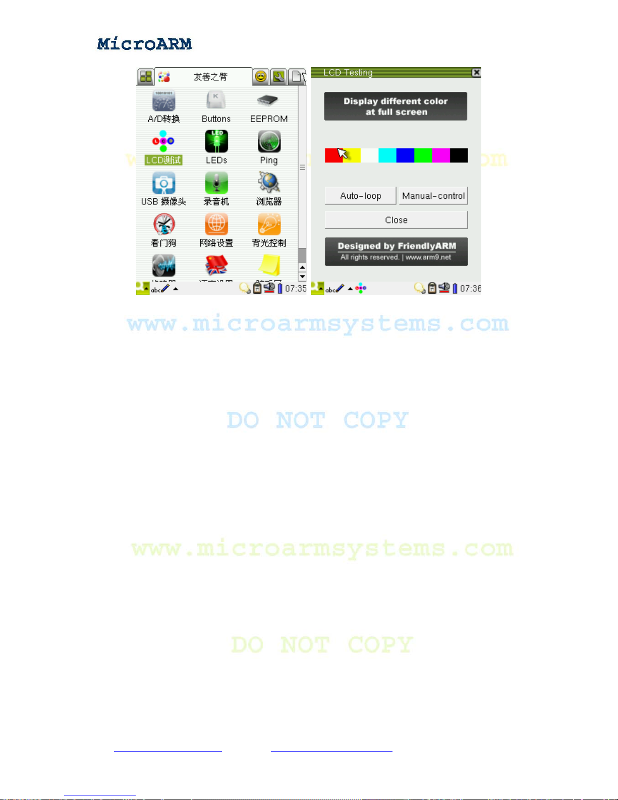
High Performance Low Cost Embedded Systems
This utility has two test modes: auto and manual.
Auto-loop loops automatically. By executing in this mode, it will display red, yellow, white, cyan,
blue, green, pink and black eight colors sequentially. During this process, click anywhere on the
screen, the system will end the test.
Manual-control is run manually. By executing in this mode, every single click on the screen will
change the screen from one color to another until it displays red, yellow, white, cyan, blue, green,
pink and black eight colors.
3.1.21 Backlight Control
In the “FriendlyARM” subgroup, click on the “backlight testing” icon:
Copy right reserved © MicroArm Systems, Inc. 1612 2
nd
Ave. SW PMB#108, Cullman, AL 35055 - 74 -
Website : www.microarmsystems.com Email: [email protected] Phone: 1-888-417-9266
Page 75
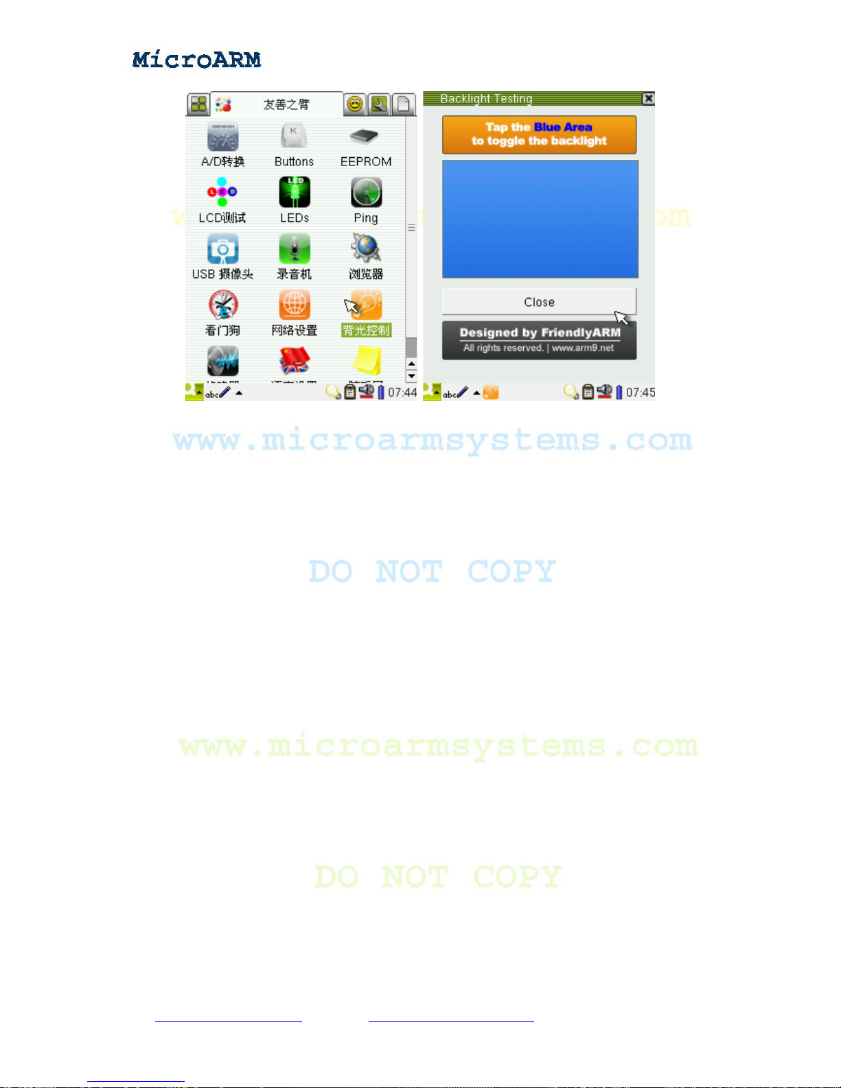
High Performance Low Cost Embedded Systems
Follow the prompt, click on the blue area, you will close the backlight. Note:you just close the
backlight, all the running program are still active. Click on the blue area again, the backlight will be
turned on again.
3.1.22 A/D Conversion
The Samsung S3C2440 chip has 8 A/D conversion channels but only one converter. In general,
AIN4, AIN5, AIN6 and AIN7 are used as YM, YP, XM and XP channels via a four wire resistor. We
extended AIN0-3 which reside on CON4. For easier testing, AIN0 is directly connected to an
adjustable resistor W1. How do they share a common converter? The following screenshots will
show you how:
Click on the “ADC Testing” icon in the “FriendlyARM” subgroup:
Copy right reserved © MicroArm Systems, Inc. 1612 2
nd
Ave. SW PMB#108, Cullman, AL 35055 - 75 -
Website : www.microarmsystems.com Email: [email protected] Phone: 1-888-417-9266
Page 76
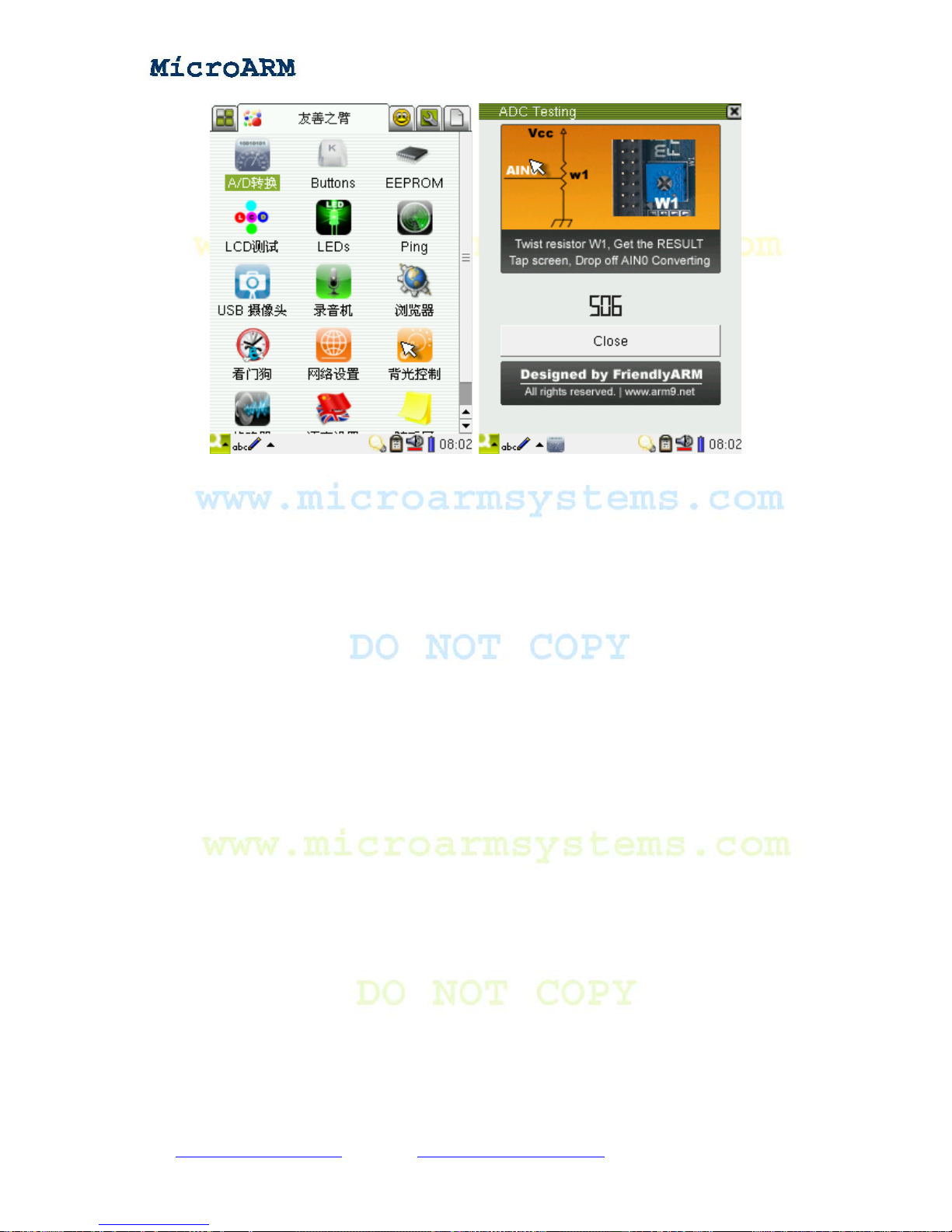
High Performance Low Cost Embedded Systems
Turning the W1 adjustable resistor, you will see the conversion changes. It has 10 digit precision,
therefore the minimum value is close to 0 and the maximum value is close to 1024.
When you click on the touch screen, the A/D converter will take the touch screen as the channel,
you will see the result “-1”; when you move your touch pen away from the screen, the A/D converter
will take AIN0 as the channel again.
Note: the W1 adjustable resistor is hidden under the LCD, to test it, you might need to remove the
LCD
3.1.23 Testing User Buttons
Note: the user buttons don’t have special functions, they are just for testing low level drivers.
Click on the “Buttons” icon in the “FriendlyARM” subgroup:
Copy right reserved © MicroArm Systems, Inc. 1612 2
nd
Ave. SW PMB#108, Cullman, AL 35055 - 76 -
Website : www.microarmsystems.com Email: [email protected] Phone: 1-888-417-9266
Page 77
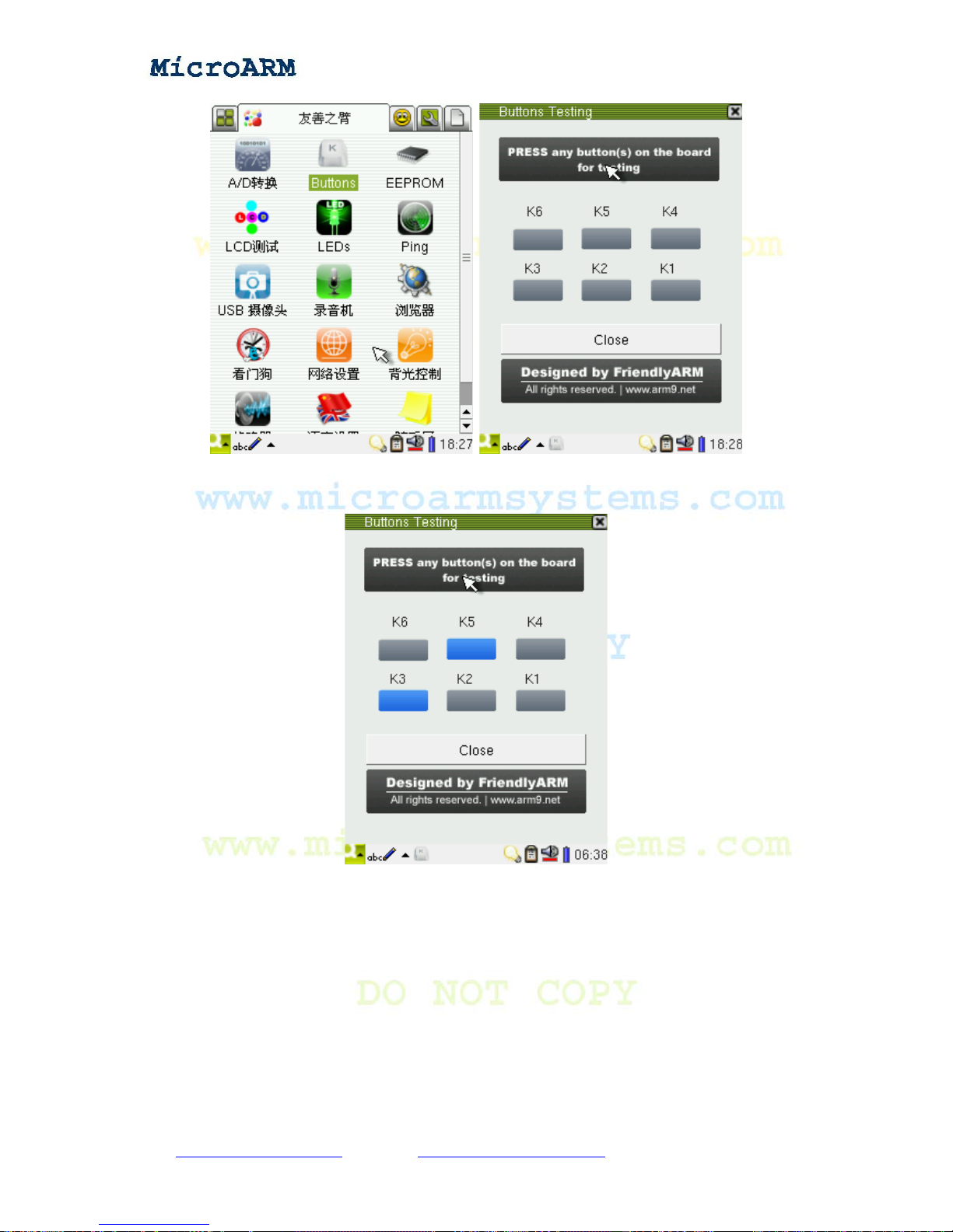
High Performance Low Cost Embedded Systems
Press down any buttons on the board, the corresponding button icons will change to blue, release
them, their icons will change back to grey.
3.1.24 Testing Touch Pen
To test whether or not a touch pen works accurately, you can draw a line on the LCD, check if
there is any offset or vibration. This can be done via the “penpad” utility. Click on the “penpad”
icon in the “FriendlyARM” subgroup:
Copy right reserved © MicroArm Systems, Inc. 1612 2
nd
Ave. SW PMB#108, Cullman, AL 35055 - 77 -
Website : www.microarmsystems.com Email: [email protected] Phone: 1-888-417-9266
Page 78
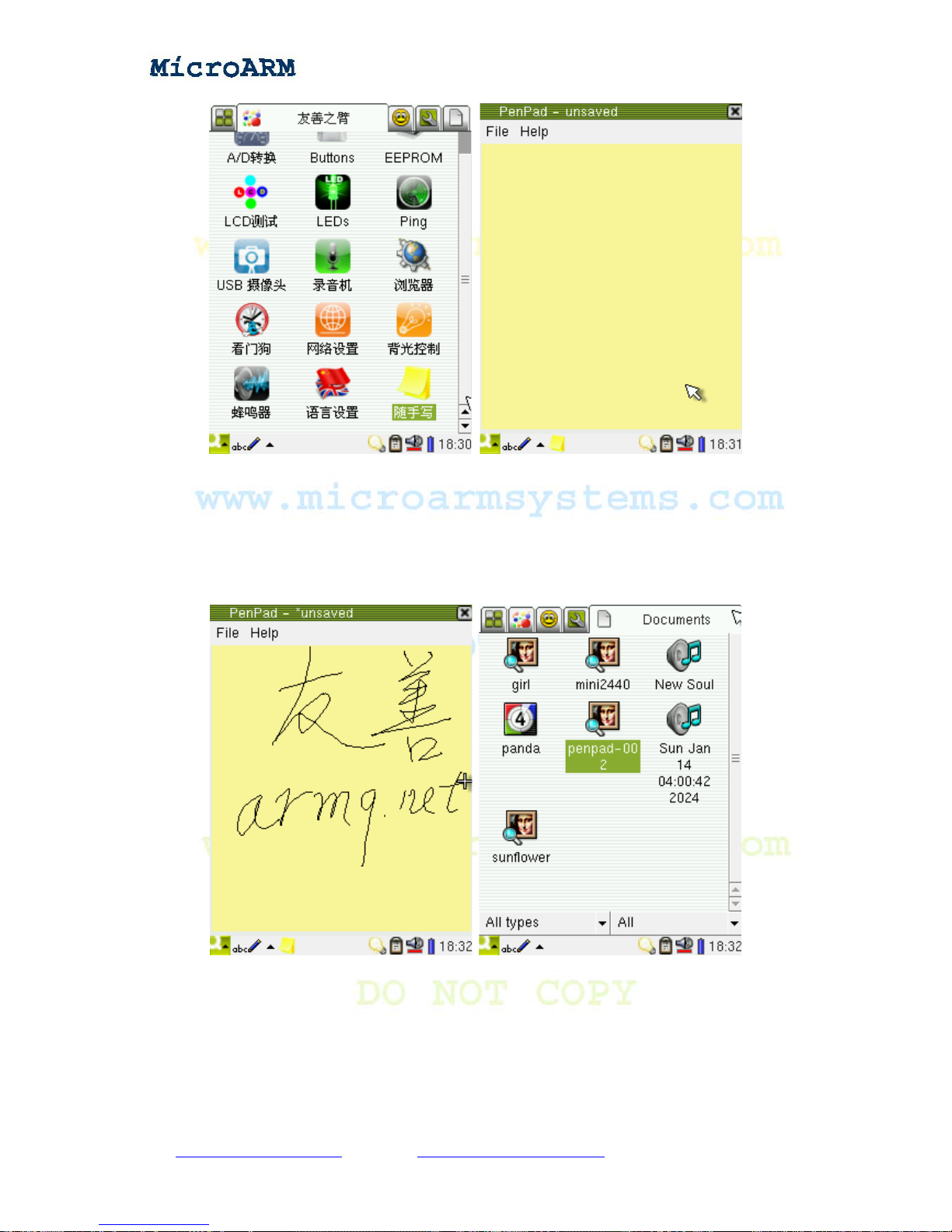
High Performance Low Cost Embedded Systems
The “penpad” utility is an easy to use program developed by FriendlyARM. Start it, a yellow
drawing area will show up. Draw whatever you like in the area (the pen color is black, its width is 1
pixel), go to “File” -> “Save”, you will save what you draw to a png file(in the “Documents”
subgroup, the /Documents/image/png/ directory). The file name begins with 001. The maximum
number of files that can be saved is 999. The following screenshot shows that our writing was smooth
which meant our pen was accurate.
Copy right reserved © MicroArm Systems, Inc. 1612 2
nd
Ave. SW PMB#108, Cullman, AL 35055 - 78 -
Website : www.microarmsystems.com Email: [email protected] Phone: 1-888-417-9266
Page 79
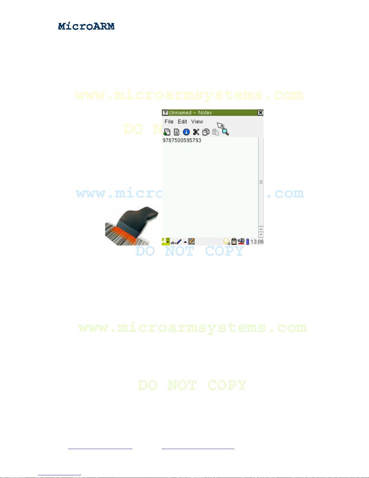
High Performance Low Cost Embedded Systems
3.1.25 Barcode Scanning
Our system supports USB barcode scanners which are actually a HID device very similar to a USB
keyboard. Therefore a barcode scanner can work any where a USB keyboard works.
Note: before start this utility, please make sure to plug in your scanner.
Click on the “text editor” icon in the “Application Programs” subgroup, scan a code with your
scanner, then you will see the code number displayed in the editor.
3.1.26 Language Setting
Qtopia 2.2.0 has a language setting utility which is different from the one in Qtopia 1.7.0. It only
supports English. Therefore we developed a new utility located in the “FriendlyARM” subgroup.
Copy right reserved © MicroArm Systems, Inc. 1612 2
nd
Ave. SW PMB#108, Cullman, AL 35055 - 79 -
Website : www.microarmsystems.com Email: [email protected] Phone: 1-888-417-9266
Page 80
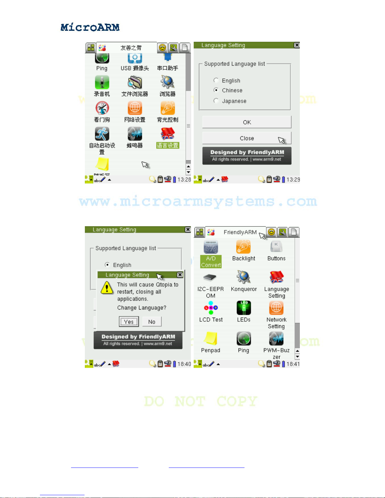
High Performance Low Cost Embedded Systems
It now supports three languages: English, Chinese and Japanese. When you select “English”, then
click on “OK”, a message will popup asking you if you want to change your language setting.
Clicking on “Yes” Qtopia will reboot; clicking on “No” it will return. (Note: the Chinese and
Japanese versions only translate program names).
Copy right reserved © MicroArm Systems, Inc. 1612 2
nd
Ave. SW PMB#108, Cullman, AL 35055 - 80 -
Website : www.microarmsystems.com Email: [email protected] Phone: 1-888-417-9266
Page 81
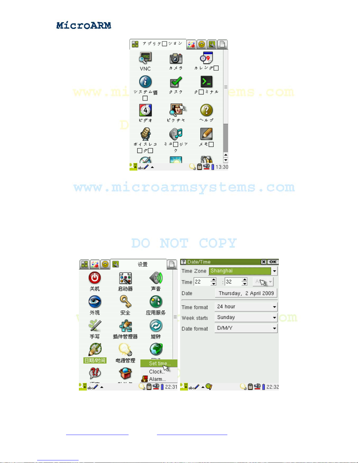
High Performance Low Cost Embedded Systems
3.1.27 Setting up Time Zone, Date, T ime and Alarm Clock
When you get our system, the date and time usually might not be accurate. You can adjust them
by yourself. Because the CPU has its own RTC and the board has a backup battery, after you adjust
the date and time, they will be saved. To adjust them, click on the time zone area at the right bottom
of the screen, a menu will show up, please select “Set time..”, open the setting interface where you
can set parameters such as time zone, date, time and so on.
Select “Clock” from the menu, click on “Stop Watch” to open a stopwatch utility
Copy right reserved © MicroArm Systems, Inc. 1612 2
nd
Ave. SW PMB#108, Cullman, AL 35055 - 81 -
Website : www.microarmsystems.com Email: [email protected] Phone: 1-888-417-9266
Page 82
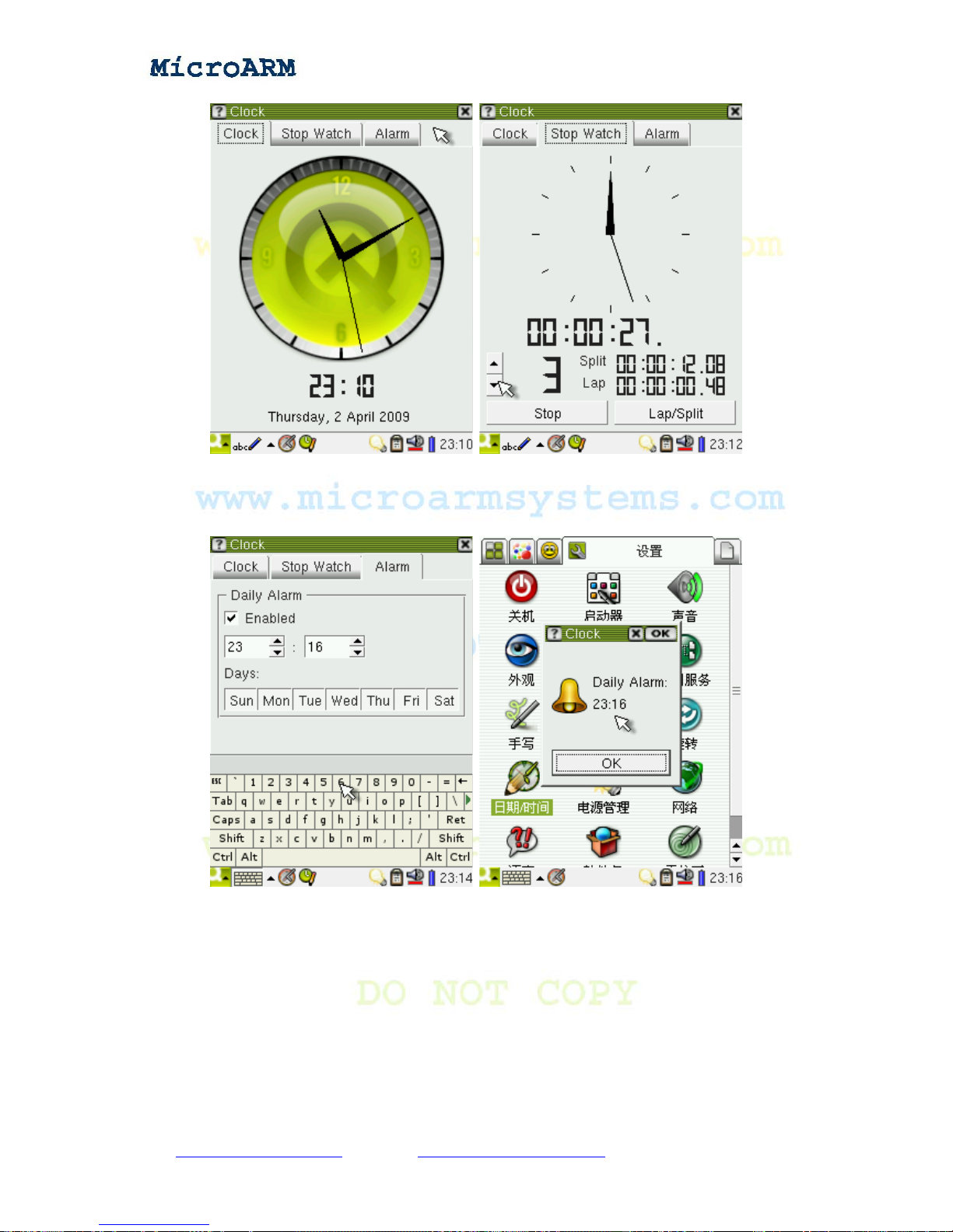
High Performance Low Cost Embedded Systems
Besides you can set the alarm clock. When it is triggered, you will hear a beeping sound which lasts
about one minute and the following popup window will show up. Click on “OK” to close the alarm
clock.
3.1.28 Rotating Screen
Click on the “rotation” icon in the “settings” subgroup to enter its interface. You can rotate the
screen in four directions.
Copy right reserved © MicroArm Systems, Inc. 1612 2
nd
Ave. SW PMB#108, Cullman, AL 35055 - 82 -
Website : www.microarmsystems.com Email: [email protected] Phone: 1-888-417-9266
Page 83
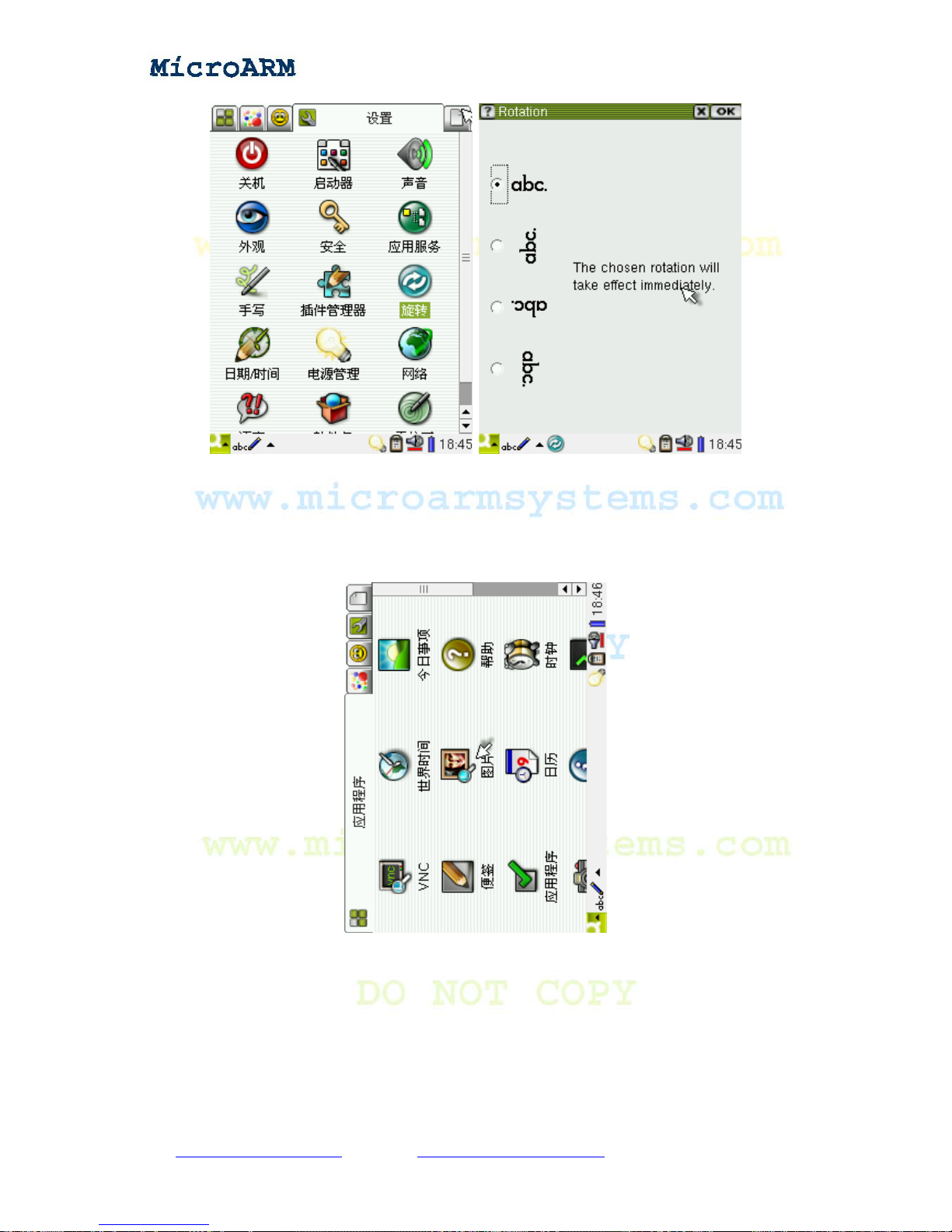
High Performance Low Cost Embedded Systems
Select the direction you want, click on “OK” you will see the screen rotate.
Note: sometimes you need to reboot Qtopia to see the rotation. It is a Qtopia utility and we hasn’t
made any change to it. In addition the rotation effect is implemented via Qtopia software and has
nothing to do with LCD drivers.
3.1.29 Setting up Auto Run Programs
By setting “auto run” you can set Qtopia to run its own or your programs after it boots up. It is
very similar to what you see in Windows “Programs -> Startup”.
Copy right reserved © MicroArm Systems, Inc. 1612 2
nd
Ave. SW PMB#108, Cullman, AL 35055 - 83 -
Website : www.microarmsystems.com Email: [email protected] Phone: 1-888-417-9266
Page 84
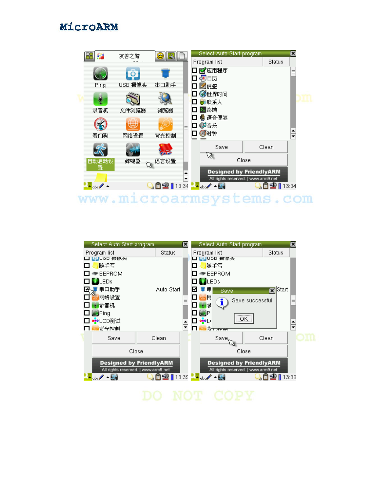
High Performance Low Cost Embedded Systems
Click on the “Auto Start Program” icon in the “FriendlyARM” subgroup.
Those program listed are available programs which include all Qtopia programs, the status column indicates
whether a program is set to auto start. The status is unique. For instance, if the “Serial Port Assistant” is checke d, its
status will show “Auto Start”, click on “Save”, a message box will pop up prompting that the net setting has been
successfully saved. Close this utility, reboot the system you will see the “Serial Port Assistant” is auto run.
To disable auto run for a program, just click on “Clean” and “Close”, a message box will pop up,
click on “Yes” the auto run for that program will be disabled.
Copy right reserved © MicroArm Systems, Inc. 1612 2
nd
Ave. SW PMB#108, Cullman, AL 35055 - 84 -
Website : www.microarmsystems.com Email: [email protected] Phone: 1-888-417-9266
Page 85
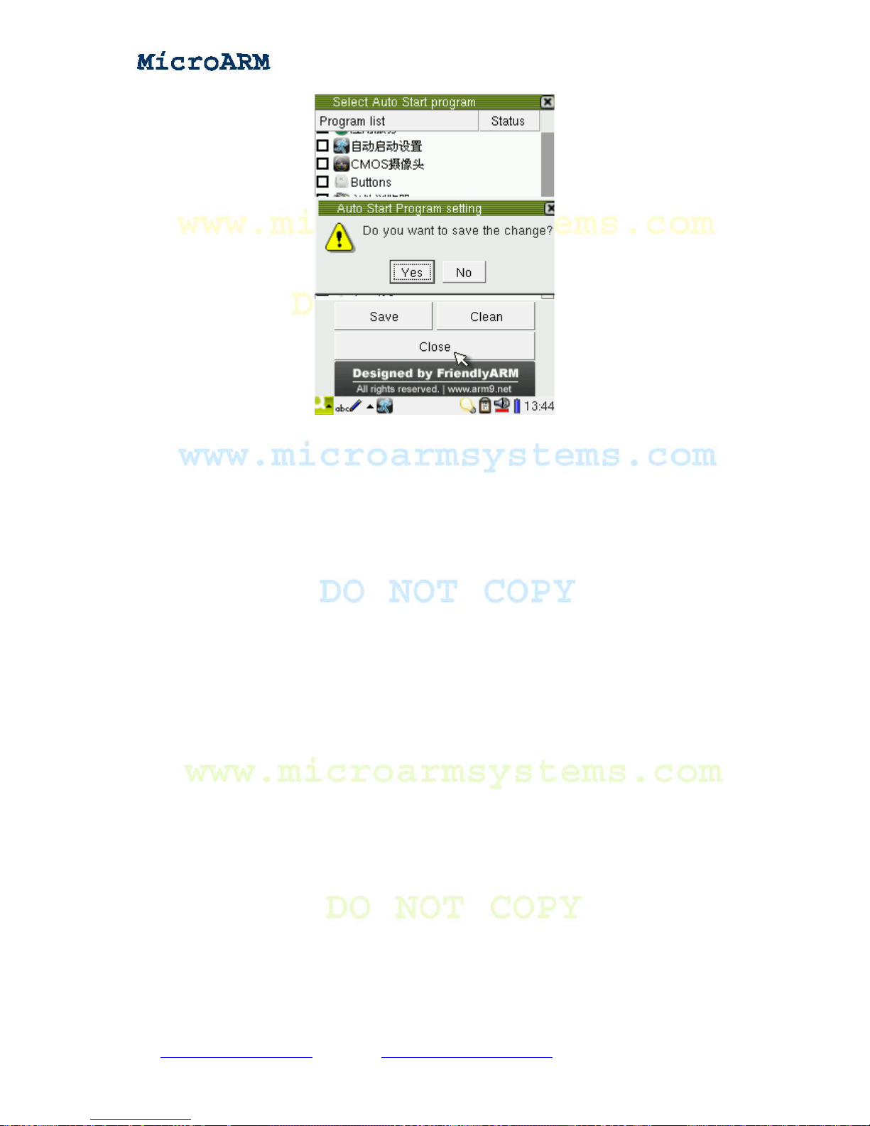
High Performance Low Cost Embedded Systems
3.1.30 System Shutdown
In the “Setting” subgroup, click on the “shutdown” icon you will see four options on the
shutdown window.
Shutdown: Press this button, Linux will end all the programs and services to shutdown the whole
system. After the whole system is shutdown, the CPU will not be running and the system consumes
lest power. However since our system doesn’t have a hardware power down circuit you still can see
the power LED on the board is on.
Reboot: This is a “hot” reboot button. If your system boots from the Nor Flash, after you press
this button, the system will shutdown, reboot and enter the supervivi main menu. If your system
boots from the Nand Flash, after you press this button, the system will shutdown, reboot and enter
the Qtopia interface.
Note: Reboot is different from the “Watchdog” function we will introduce. The “Watchdog” is
“cold” reboot and doesn’t end programs or services but reset the system instead.
Restart Server: it restarts the Qtopia system only. It doesn’t interrupt the running Linux.
Terminates Server: it shuts down the Qtopia system. After press this button, the Qtopia interface
will be disabled. What is left on the screen is the left data in RAM and it is not an active graphic
interface.
Copy right reserved © MicroArm Systems, Inc. 1612 2
nd
Ave. SW PMB#108, Cullman, AL 35055 - 85 -
Website : www.microarmsystems.com Email: [email protected] Phone: 1-888-417-9266
Page 86
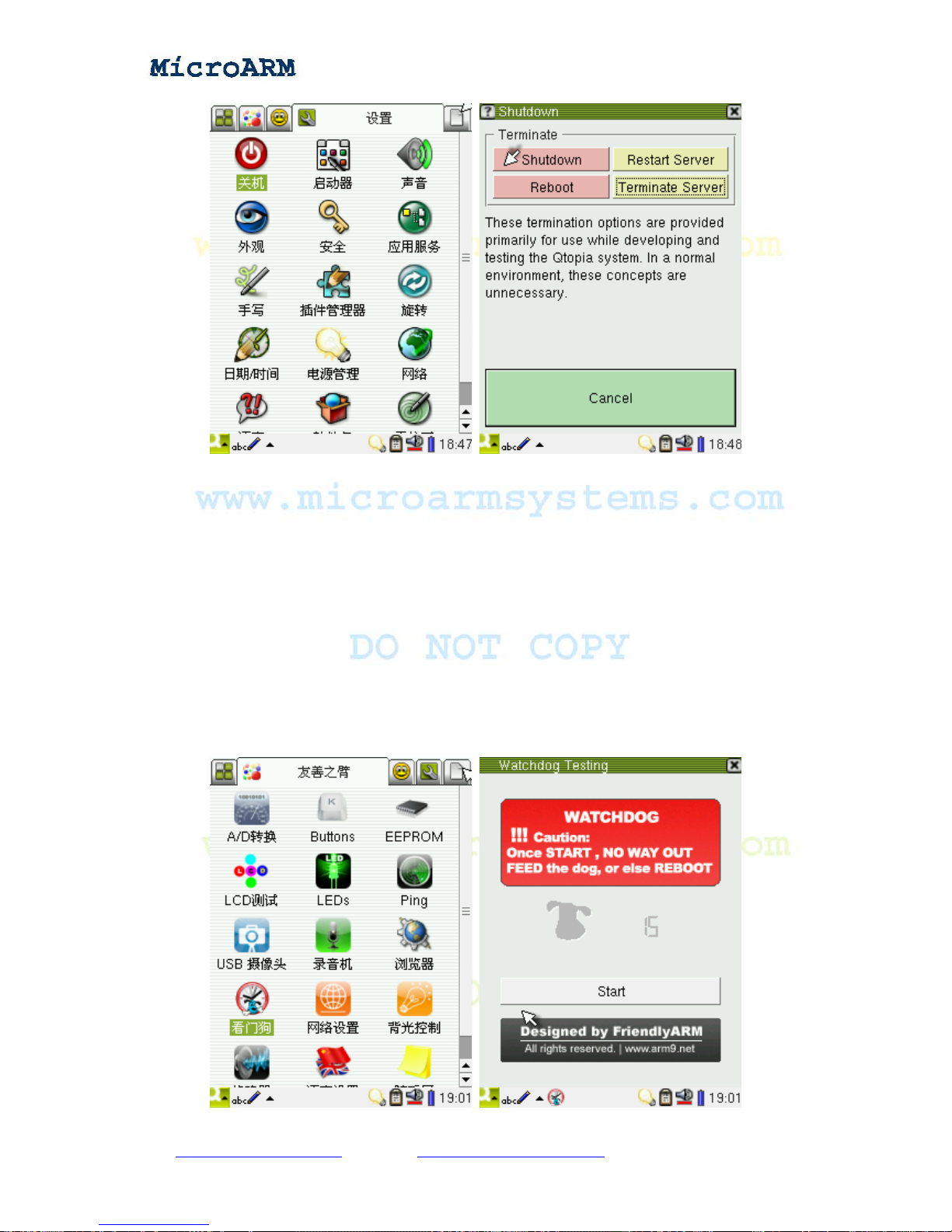
High Performance Low Cost Embedded Systems
There is a “brightness and power” icon in the “setting” subgroup. Since our system doesn’t have
a power management circuit, this icon is not active.
Note: the original Qtopia 2.2.0 system doesn’t “shutdown” or “reboot” effectively, we changed
its code to make it work.
3.1.31 Watchdog
The “Watchdog” is a very basic utility in embedded systems. The S3C2440 chip already has a
watchdog. The latest Linux kernel has drivers for it.
Click on the “Watchdog” icon in the “FriendlyARM” subgroup
Copy right reserved © MicroArm Systems, Inc. 1612 2
nd
Ave. SW PMB#108, Cullman, AL 35055 - 86 -
Website : www.microarmsystems.com
Email: [email protected] Phone: 1-888-417-9266
Page 87
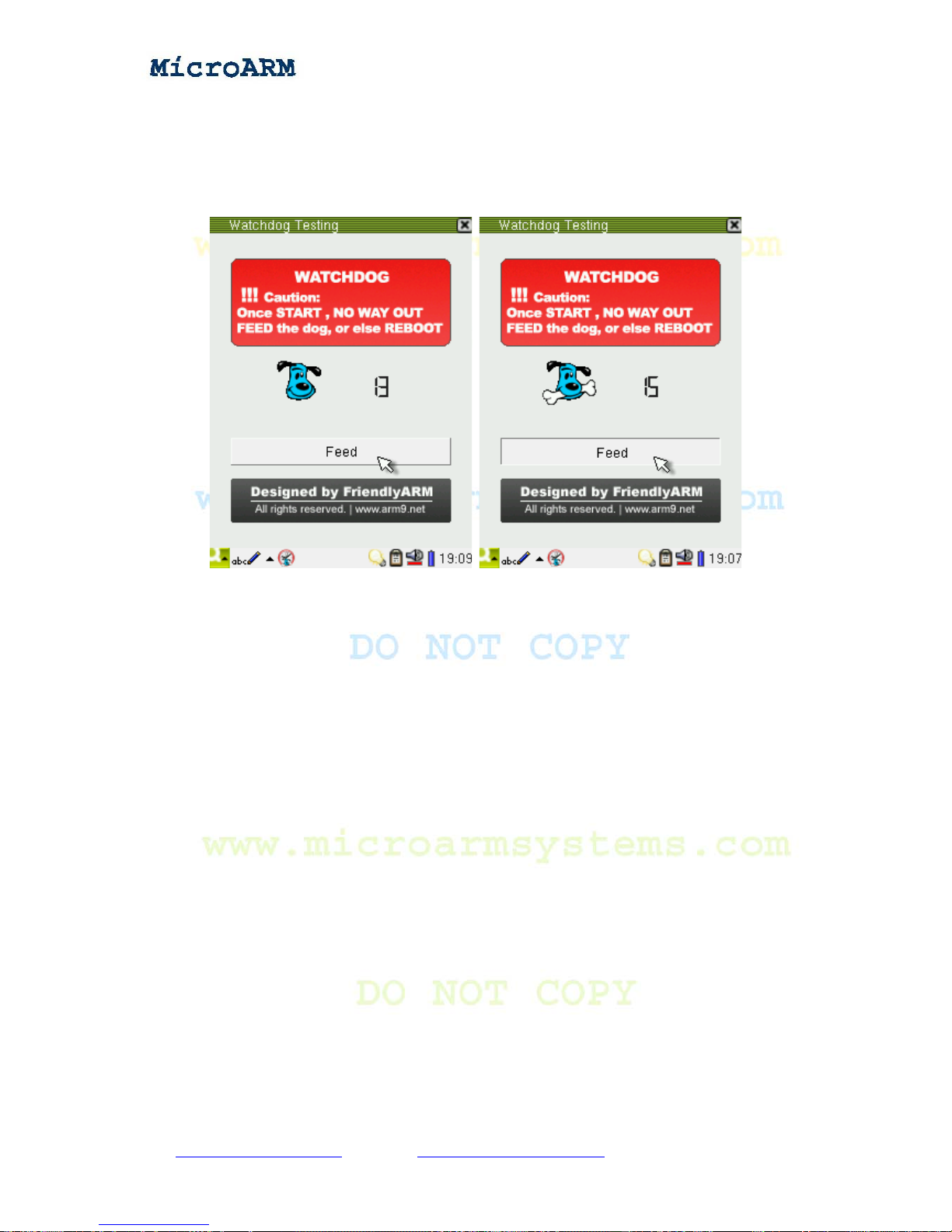
High Performance Low Cost Embedded Systems
Note: before take any action, please read the notes in the red area: once start, no way out, feed the
dog, or else reboot!
Here we set a countdown time 15 seconds. To feed the dog, click on the “Feed” button. Keep
feeding, it will always have bones and the system will not reboot.
3.2 Operating MINI2440 Linux via Super Terminal
This section will give a brief introduction on how to run Linux commands and various
application programs in Linux via a super terminal. Before move forward, please connect your
board with a PC and start a super terminal. The following screenshot is what you might see after
you set up your super terminal and connection with your board.
Copy right reserved © MicroArm Systems, Inc. 1612 2
nd
Ave. SW PMB#108, Cullman, AL 35055 - 87 -
Website : www.microarmsystems.com Email: [email protected] Phone: 1-888-417-9266
Page 88
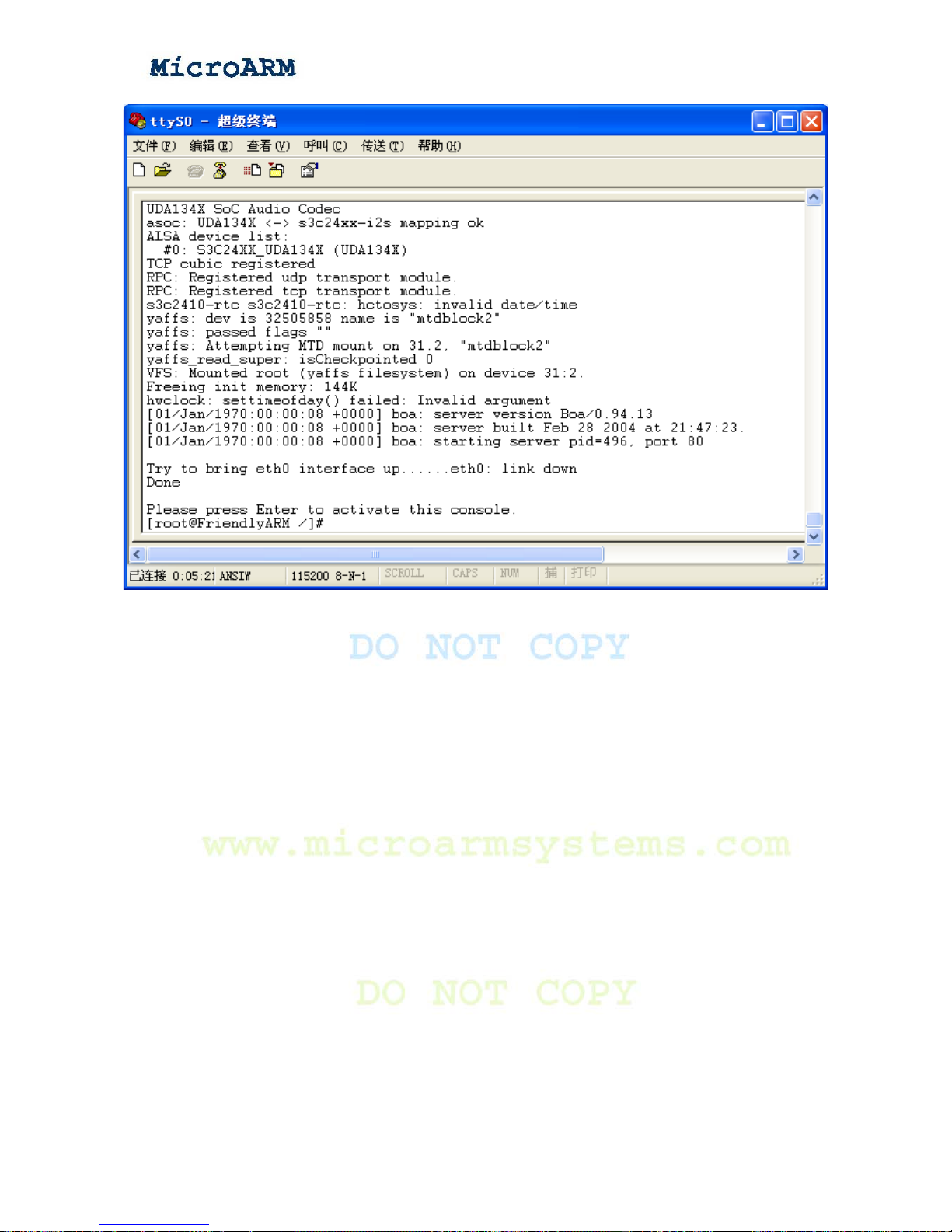
High Performance Low Cost Embedded Systems
3.2.1 Mounting a USB Drive/Portable Hard Disk
After inserting a USB drive, the system will automatically create a “/udisk” directory and mount
the drive on it, you will see the following messages:
Copy right reserved © MicroArm Systems, Inc. 1612 2
nd
Ave. SW PMB#108, Cullman, AL 35055 - 88 -
Website : www.microarmsystems.com Email: [email protected] Phone: 1-888-417-9266
Page 89
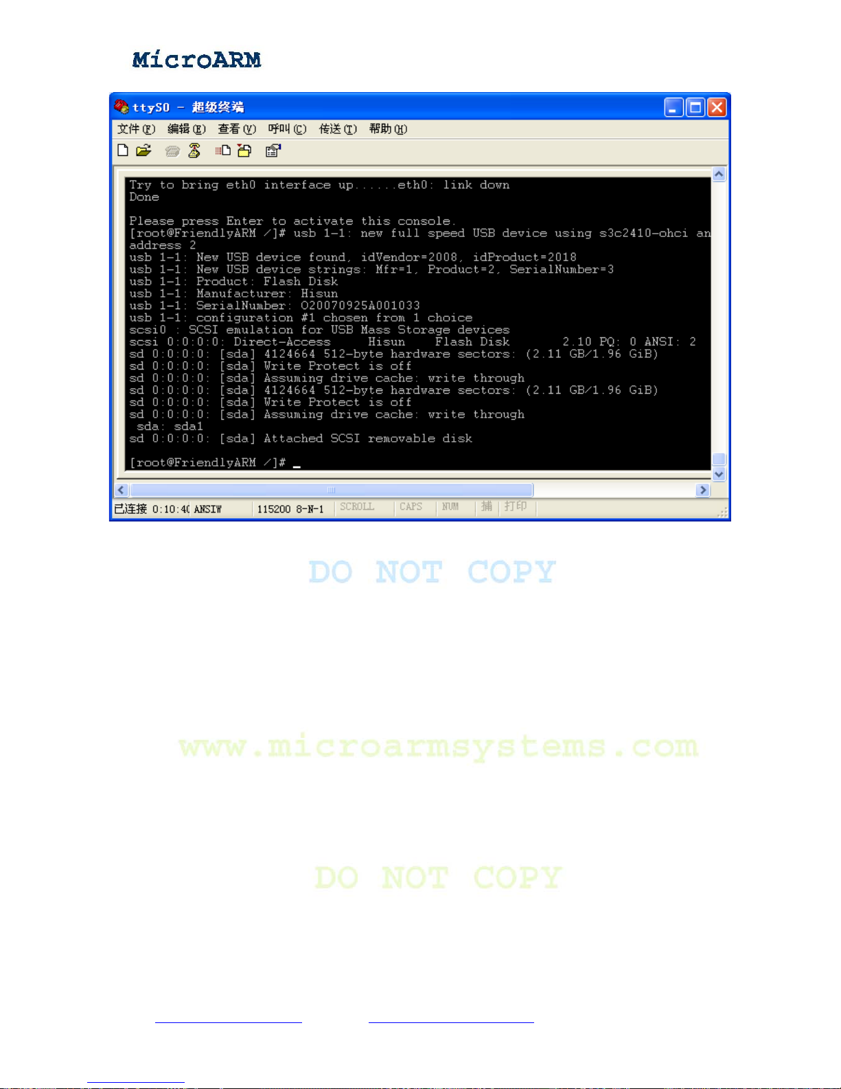
High Performance Low Cost Embedded Systems
The USB drive has a device name “/dev/udisk”. Entering the “/udisk” directory, you will be able
to browse its contents. Note: if your drive cannot be detected, please check whether it is
FAT32/VFAT.
Copy right reserved © MicroArm Systems, Inc. 1612 2
nd
Ave. SW PMB#108, Cullman, AL 35055 - 89 -
Website : www.microarmsystems.com Email: [email protected] Phone: 1-888-417-9266
Page 90
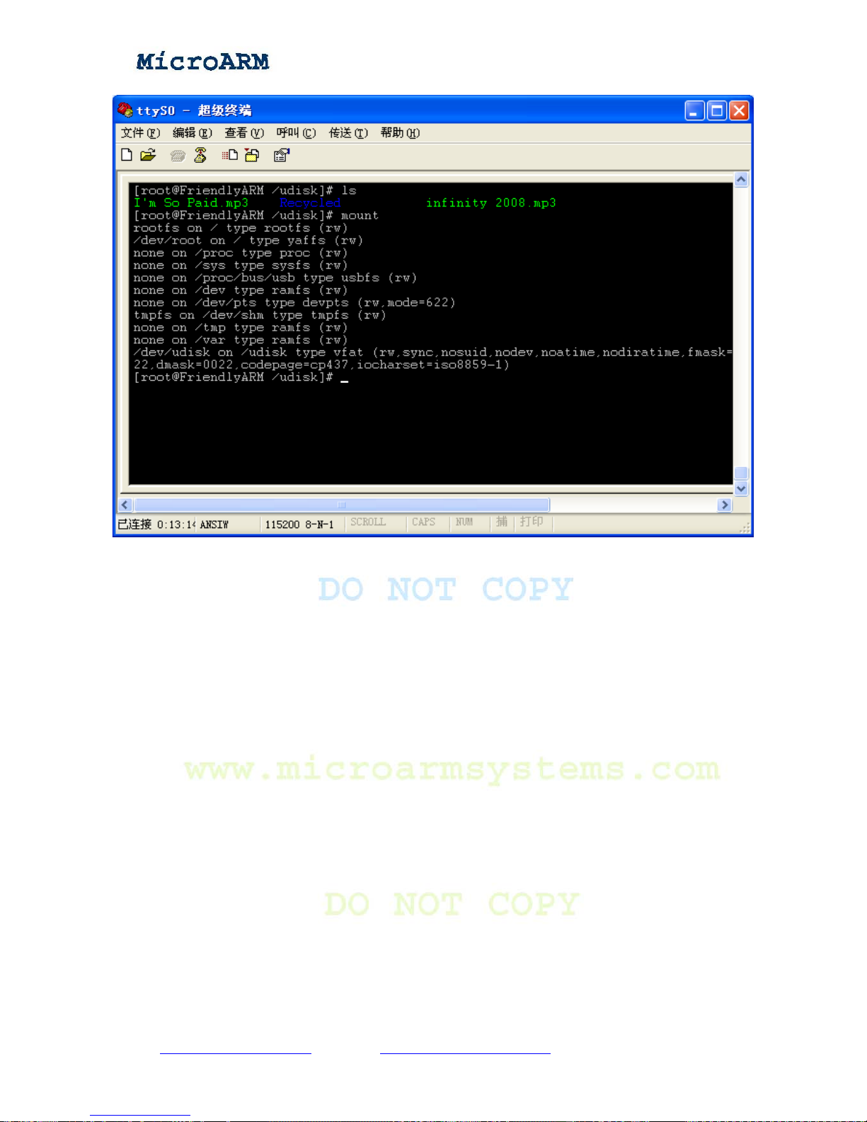
High Performance Low Cost Embedded Systems
3.2.2 Mounting a SD Card
Similar to USB drive mounting, a SD card will be automatically detected and mounted. After
inserting a SD card, you will see the following messages:
Copy right reserved © MicroArm Systems, Inc. 1612 2
nd
Ave. SW PMB#108, Cullman, AL 35055 - 90 -
Website : www.microarmsystems.com Email: [email protected] Phone: 1-888-417-9266
Page 91
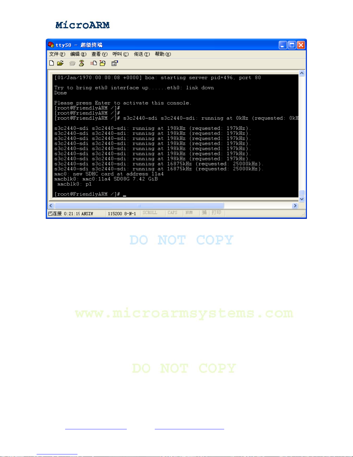
High Performance Low Cost Embedded Systems
The system will create a “/sdcard” directory and mount the SD card on it.
Copy right reserved © MicroArm Systems, Inc. 1612 2
nd
Ave. SW PMB#108, Cullman, AL 35055 - 91 -
Website : www.microarmsystems.com Email: [email protected] Phone: 1-888-417-9266
Page 92
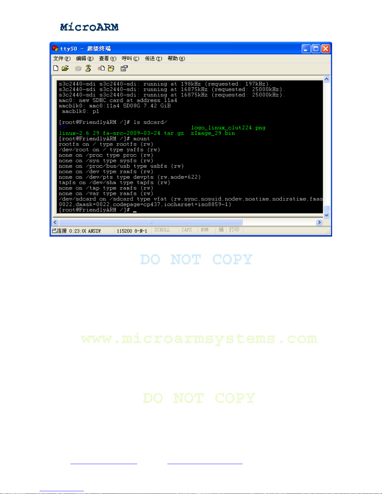
High Performance Low Cost Embedded Systems
3.2.3 Mounting a CMOS Camera
Connect a CAM130 camera to your board’s CAMERA interface, power on your board and login
the system. Type the “camtest” command you will see the following screenshot:
Copy right reserved © MicroArm Systems, Inc. 1612 2
nd
Ave. SW PMB#108, Cullman, AL 35055 - 92 -
Website : www.microarmsystems.com Email: [email protected] Phone: 1-888-417-9266
Page 93
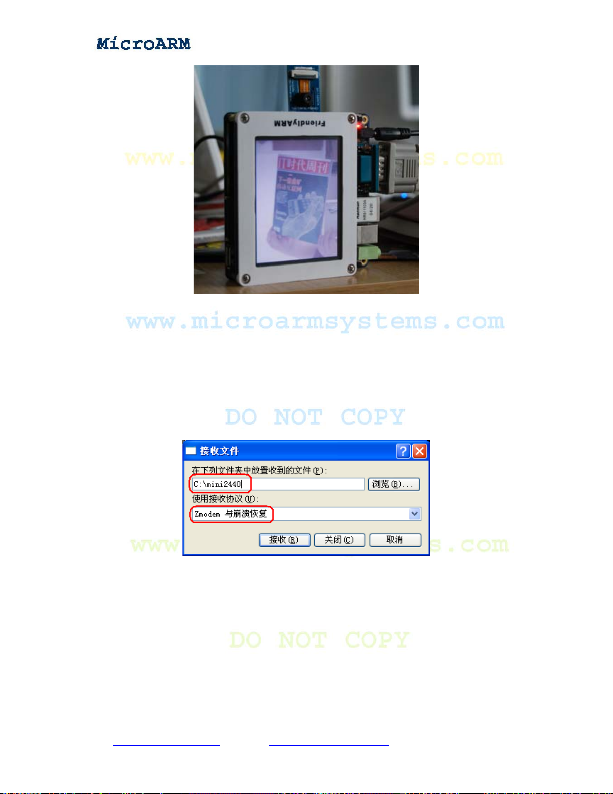
High Performance Low Cost Embedded Systems
3.2.4 File Transfers to and from a PC via a Serial Port
After login into the MINI2440 system via a serial port, you can transfer files to and from a host
PC by using command “rz”or “sz” as follows:
(1) Transfering files by using “sz”
Open a super teminal, click on the mouse’s right button, then click on “Receive files” to set up
the destination directory and the protocol this transfer will use, see the screenshot below:
Type “sz /shanghaitan.mp3” in the shell to transfer the “shanghaitan.mp3” file under the “/”
directory to the host PC. It took a while to transfer this big file. After it is done, the system will save
it in the directory you set in the previous step. Please see the screen-shot below:
Copy right reserved © MicroArm Systems, Inc. 1612 2
nd
Ave. SW PMB#108, Cullman, AL 35055 - 93 -
Website : www.microarmsystems.com Email: [email protected] Phone: 1-888-417-9266
Page 94
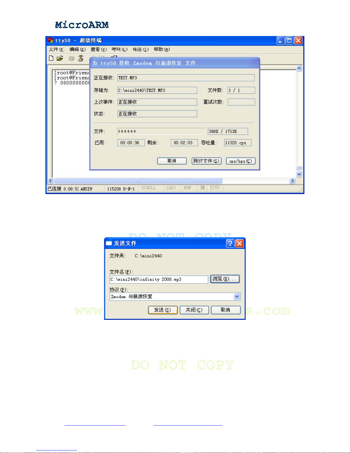
High Performance Low Cost Embedded Systems
(2) Transfering files by using “rz”
In your MINI2440 system, type “rz” to receive files from a host PC.
Open a super terminal, click on the mouse’s right button, select “Send file”, set up the file being
sent and the protocol the transfer will use. Then send the file:
Copy right reserved © MicroArm Systems, Inc. 1612 2
nd
Ave. SW PMB#108, Cullman, AL 35055 - 94 -
Website : www.microarmsystems.com Email: [email protected] Phone: 1-888-417-9266
Page 95
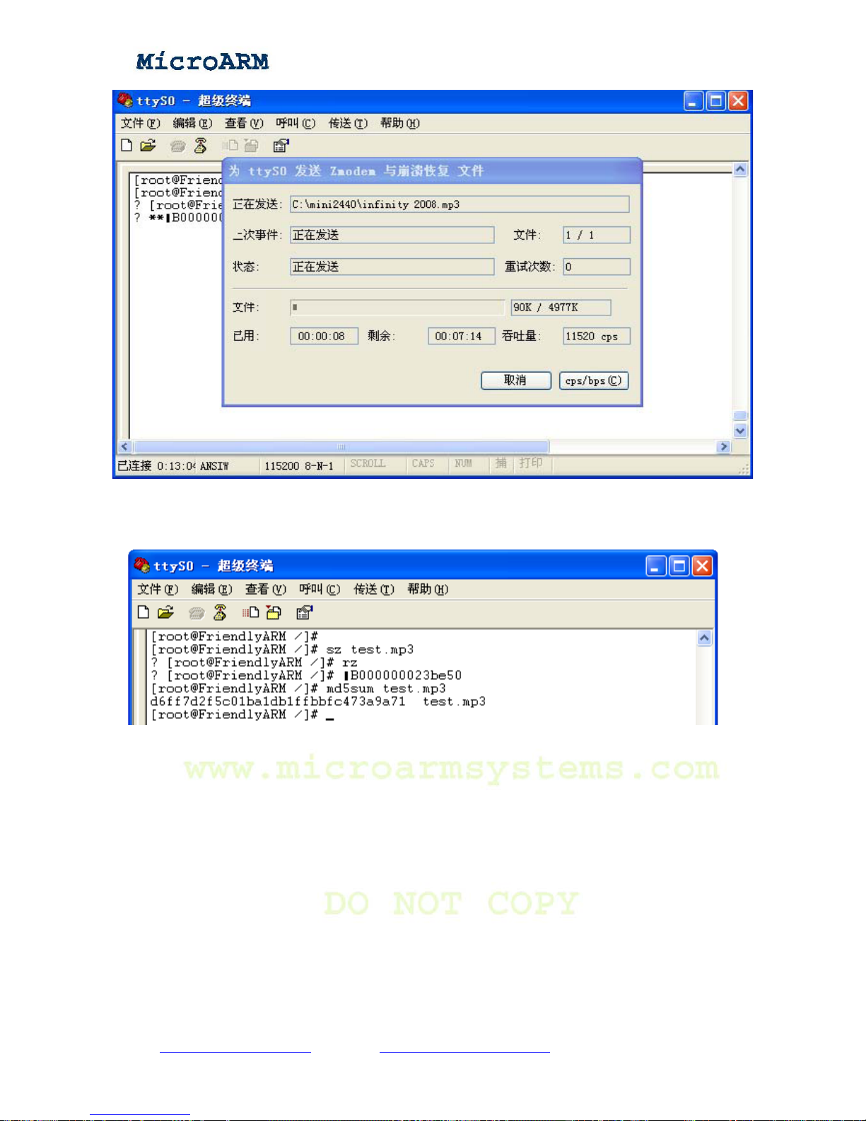
High Performance Low Cost Embedded Systems
After the transfer is done, the current directory will get this file. You can verify it by using
“md5sum” to check whether this file is the same as the original one.
Copy right reserved © MicroArm Systems, Inc. 1612 2
nd
Ave. SW PMB#108, Cullman, AL 35055 - 95 -
Website : www.microarmsystems.com Email: [email protected] Phone: 1-888-417-9266
Page 96
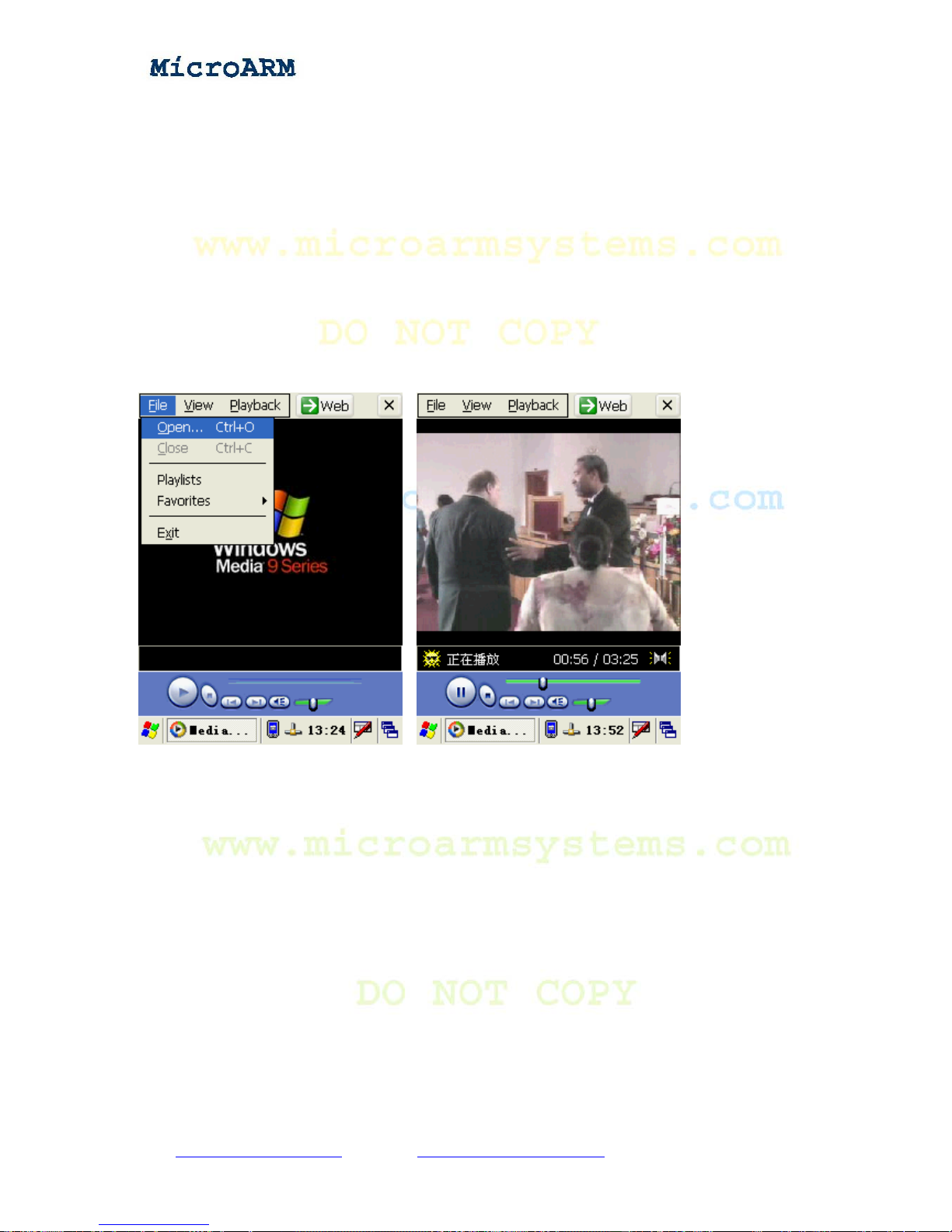
High Performance Low Cost Embedded Systems
Chapter 4 Running WinCE
4.1 Software Applications and Configurations in WinCE
4.1.1 Playing MP3
After starting WinCE, double click on the “Media Player” icon, the Windows Media Player will
pop up as shown below. Select “File”-> “Open”, follow the prompt, locate an mp3 file you want to
play, it will be run like what it does in a PC Windows system. In addition, the Media Player can also
play the WMV files.
4.1.2 File Transfer with FTP
Linux or Windows by default has a FTP command line program. Using the FTP service can
remotely login a host, transfer files to and from it. The MINI2440 system has a default FTP
command line program and starts this service on system startup. To test this service, you can login
the sytem via a command line window from a host PC and transfer files to and from it.
Note: please make sure the directory in which to run the FTP commands has the files for FTP
test. In this example, it was a “hope.mp3” file.
After the transfer is done, you can check if a “hope.mp3” file exists under “/home/plg”.
Copy right reserved © MicroArm Systems, Inc. 1612 2
nd
Ave. SW PMB#108, Cullman, AL 35055 - 96 -
Website : www.microarmsystems.com Email: [email protected] Phone: 1-888-417-9266
Page 97
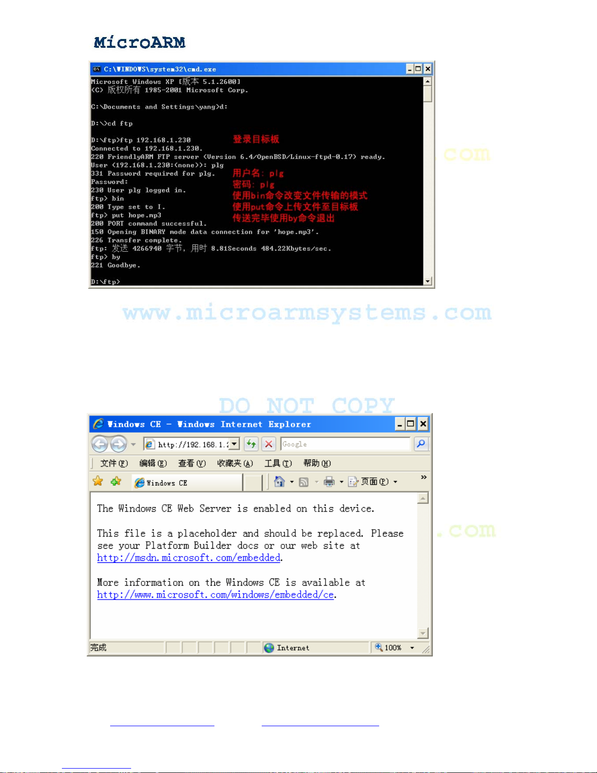
High Performance Low Cost Embedded Systems
4.1.3 Configuring Web Server
If the HTTP service is set to auto-run in WinCE, it will be started on startup. This service is what
is commonly called “web server”. Connect the MINI2440 board which runs WinCE to a host PC,
type the board’s IP address in IE’s address bar, if you see a preset home page as the example shown
below, it indicates the web server has been started.
Copy right reserved © MicroArm Systems, Inc. 1612 2
nd
Ave. SW PMB#108, Cullman, AL 35055 - 97 -
Website : www.microarmsystems.com Email: [email protected] Phone: 1-888-417-9266
Page 98
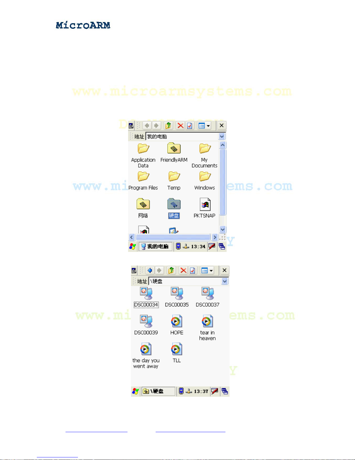
High Performance Low Cost Embedded Systems
4.2 Testing Hardware in WinCE
4.2.1 Mounting a USB Drive
Using a USB drive in WinCE is similar to Linux. After entering WinCE, plug a USB drive in the
USB host port, the power led on the USB drive will be flashing, several seconds later this drive will
be mounted on the system. Double click on the “My computer” icon, open the “resource manager”,
you will observe that a USB device has been created. Please refer to the screen shot below:
Double click on the USB drive icon, you will be able to browse its contents, read and write files.
Copy right reserved © MicroArm Systems, Inc. 1612 2
nd
Ave. SW PMB#108, Cullman, AL 35055 - 98 -
Website : www.microarmsystems.com Email: [email protected] Phone: 1-888-417-9266
Page 99
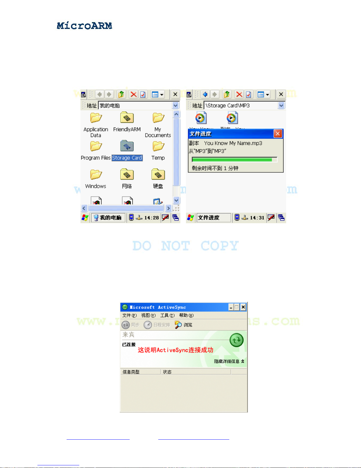
High Performance Low Cost Embedded Systems
4.2.2 Mounting a SD Card
Plug a SD card in the SD interface of the board you will be able to see a SD device “Storage
Card” is created in the “resource manager”. Double click on the SD card icon, you will be able to
browse its contents, read and write files.
4.2.3 Connecting a USB Device via ActiveSync
Note: Please use the “\windows platform tools\CE ActiveSync USB driver” to install a USB
driver.
After successfully installing the driver and the ActiveSync application, connect the MINI2440
board to a host PC, if everything goes smoothly, you will see the screen shot below:
Copy right reserved © MicroArm Systems, Inc. 1612 2
nd
Ave. SW PMB#108, Cullman, AL 35055 - 99 -
Website : www.microarmsystems.com Email: [email protected] Phone: 1-888-417-9266
Page 100
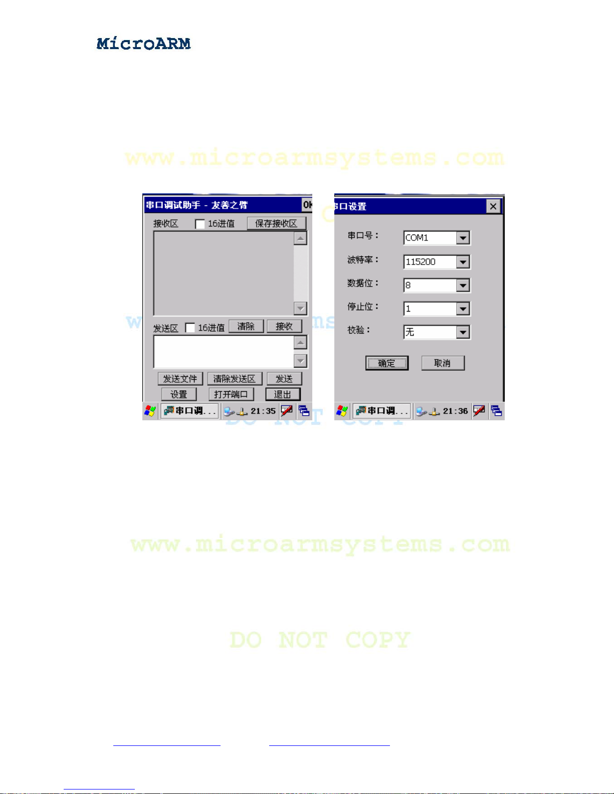
High Performance Low Cost Embedded Systems
4.2.4 Testing Serial Ports
Note: The MINI2440 system goes with a standard driver for three serial ports. To test ports 2 and
3, you need to utilize the shipped extended serial port board.
After booting the system, click running the “SComAssistant” icon on the desk like the screen
shots shown below:
Click on the “Configure” button, open the configuration window, set the serial port to “COM2”,
the “Port speed” to 115200, the others to what the above screen shots present and then click on
“OK”.
In the meantime, connect the “COM2” port on the extended board to a host PC and set up the
serial port configurations in the PC system.
On the main window, click on the “open” button, it will be changed to “close”. Type characters in
the terminal window, click on the “send” button and the PC will receive those input characters.
Please see the screen shots below:
Copy right reserved © MicroArm Systems, Inc. 1612 2
nd
Ave. SW PMB#108, Cullman, AL 35055 - 100 -
Website : www.microarmsystems.com Email: [email protected] Phone: 1-888-417-9266
 Loading...