

MICRO-AIR SC 150 Owner's Manual
AIR CLEANERS
OWNER’S MANUAL
READ COMPLETE INSTRUCTIONS BEFORE OPERATING.
PLEASE FILE FOR FUTURE REFERENCE.
MODEL SC 150
CAUTION
MODEL SC 150 SPECIFICATIONS
Input Volts: 120 Volts, 60Hz
220 Volts, 50 Hz
Maximum Current:
Draw- 120V. 2.4 amps
220V. 1.2 amps
CFM: 200 for Dual Arm Unit
150 for Single Arm Unit
dBA*: Exhaust- 63 for Dual Arm Unit
62 for Single Arm Unit
Inlet- 58 for Dual Arm Unit
57 for Single Arm Unit
*measured at 6’ distance
Dimensions: 11 1/4”h. x 14 3/8”w x 27” l.
with 3’ long arm assembly
Shipping Wt.: 53 1/2 lbs. Single Arm
55 lbs Dual Arm
Actual Wt. 45 1/2 lbs. Single Arm
47 lbs. Dual Arm
FEATURES:
• Compact size - high CFM
• Attractive paint finish
• Self supporting arm assy.
• Lighted switch
• Thermally protected, fan-cooled motor.
• Flexible design for bench top, under table or wall
mount applications.
• Easy access to all parts for service and maintenance.
3. Looking inside the unit, remove the two (2) filter spring
retainers and pull out the foam prefilter, HEPA filter and
charcoal/ purasorb filter. REMOVE THE PLASTIC WRAP
THAT PROTECTS THE CHARCOAL/ PURASORB FILTER
DURING STORAGE.
4. Remove the arm assembly from the second carton consisting
of one or two flexible hoses and a black formed plastic
manifold. Taped to the underside of the manifold is a clear
bag containing four (4) black screws. Remove screws and
disgard bag.
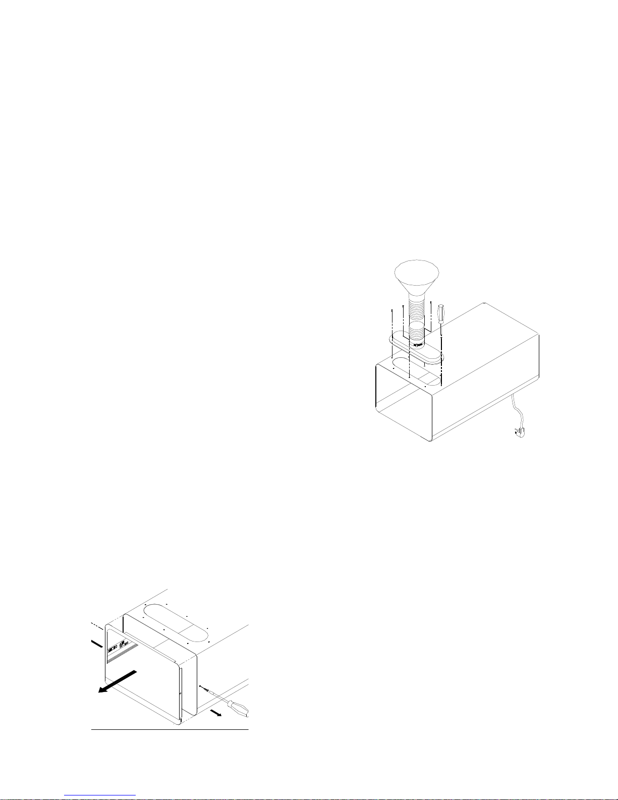
5. Place the plastic manifold upon the large oval hole on the
SC150 cabinet, align the four pre-drilled holes on the
manifold to those on the cabinet.
6. Using a slot head screw driver, secure the plastic manifold
and hose assembly to the cabinet with the four (4) self
tapping black screws obtained from step 4. (FIG. 2)
PRE-OPERATING INSTRUCTIONS
NOTE: The SC150 is shipped in two cartons. Carton 1 contains the
main unit w/ instructions. Carton 2 contains the arm (or arms)
assembly.
1. Upon receipt, remove the units from cartons. Inspect for any
freight damage that may have occured during shipping.
Report any damage to the freight company.
2. Remove filter access door by removing the two phillips head
screws as shown. Grasp the underside of the door offset
and lift slightly to remove. (FIG. 1)
FIG. 1
FIG. 2
7. Re-install filters removed in step 2 and secure with filter
spring retainer. NOTE: Filters should be pressed firmly into
unit for positive seal resulting in no filter bypass. Replace
the filter access door.
NOTE: INSTALL CHARCOAL FILTER BEFORE HEPA
FILTER.
OPERATION
1. Before operating, simply plug the SC150 power cord into
any grounded electrical outlet rated at nameplate voltage.
2. Once the SC150 has been plugged in, turn the unit on.
Position inlet nozzle(s) approximately 6” from point of
containment to be captured.
IMPORTANT: TAKE CARE TO SEE THAT THE INLET
NOZZLE(S) DO NOT TOUCH HOT SURFACES SUCH
AS SOLDERING IRONS, WHICH WOULD BE RESULT
IN THE DEFORMATION OF THE PLASTIC NOZZLE.
3. The SC150 has a fan-cooled, thermally protected motor,
and is designed to operate for continuous duty if required.
NOTE: After some time,the flexible hose may not hold in a horizontal
PART NO. 33085-01
position. This can be fixed by simply twisting the hose
counterclockwise thereby slightly reducing the hose diameter and
tightening the segmented joints.
OPTIONAL INSTALLATION APPLICATIONS
This section displays options available to the SC150 for specific
applications:
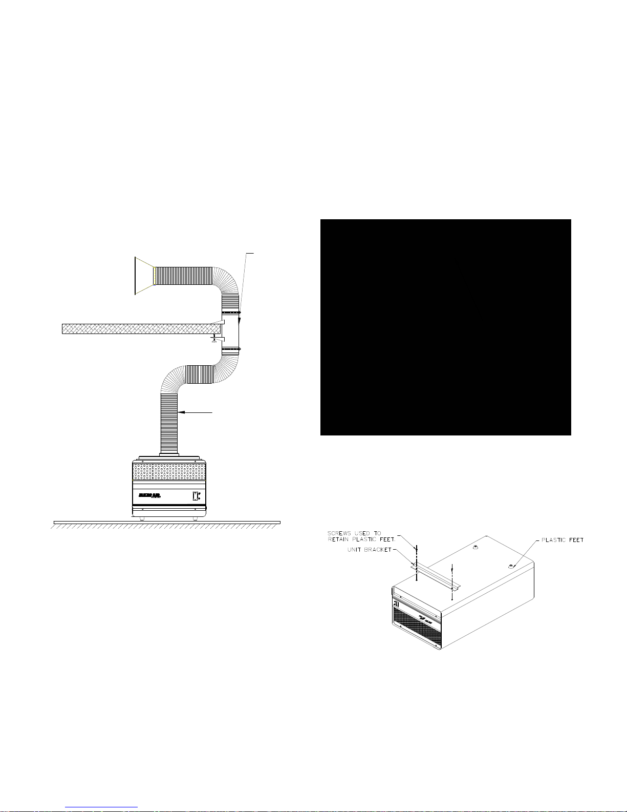
A. Table Bracket Mounting (See FIG. 3.)
1. This option is designed when the customer wishes to place
the unit on the floor and clamp the hose to a bracket on the
table. This clears space for the worker.
TABLE CLAMP
BRACKET
SC150 INSTALLATION INSTRUCTIONS FOR VERTICAL
WALL MOUNT APPLICATIONS
This kit (Part No. 33076-01) contains:
1 33078-01 Wall Bracket
1 33080-01 Unit Bracket
3 P103 #10 x 1 1/4” Long Hex Screw
1. Remove the two plastic feet near the air exhaust end of
the SC150 using a phillips head screw driver. Retain the
screws.
2. Attach the unit bracket to the bottom of the SC150 using
screws that originally secured plastic feet. (See FIG 5.)
OPTIONAL WALL
BRACKET NOT
FOR VERTICAL
INSTALLATION
PART NO. 33076-01
EXTENSION HOSE OR PVC
SUPPLIED BY OTHERS. 3"
INSIDE DIAMETER REQUIRED.
FIG. 3
B. Optional Wall Mount Assembly for Vertical
Installation. (See Fig. 4)
1. This installation allows the SC150 to be mounted on a
wall in a vertical position. The exhaust is then pointed
upward, and the arm (or arms) is at the bottom end,
close to the work area.
FIG. 4
FIG. 5
 Loading...