

MICRO-AIR RP4, RP8, RP6 Installation And Operation Manual
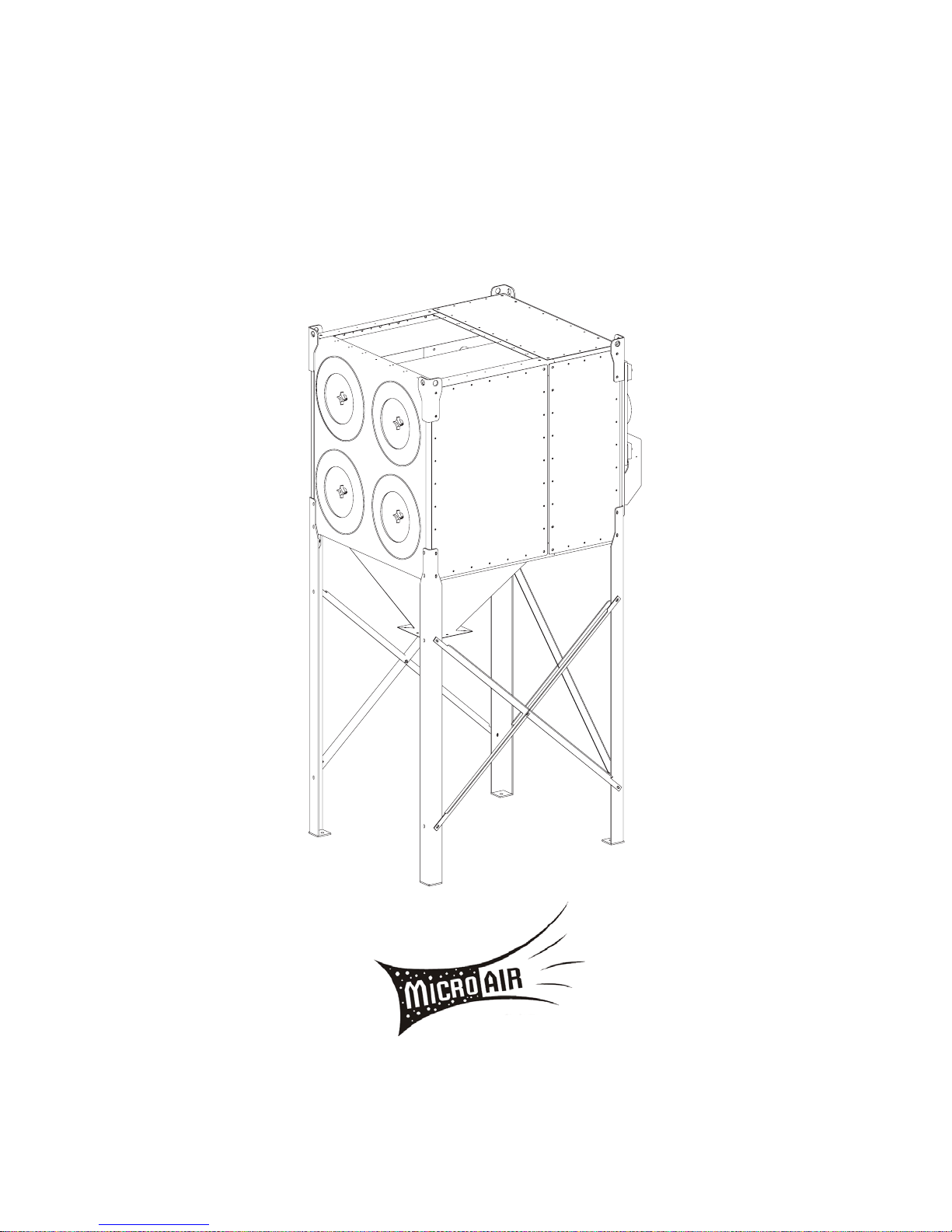
MICRO-AIR DUST COLLECTOR
Installation and Operation Manual
MODEL RP4, RP6, RP8
This manual contains specifi c cautionary statements relative to worker safety. Read this manual thoroughly
and follow as directed. It is impossible to list all the hazards of dust control equipment. It is important that
use of the equipment be discussed with a Micro Air Representative. Persons involved with the equipment or
systems should be instructed to operate in a safe manner.
Important:
1

TABLE OF CONTENTS
CAUTIONS 3
SPECIFICATIONS 4
INSTALLATION
INSPECTION 5
EQUIPMENT / TOOLS REQUIRED 5
ASSEMBLY OF UNIT 5
COMPRESSED AIR INTALLATION 6
ELECTRICAL INSTALLATION 6
UNITS INSTALLED OUTDOORS 7
UNIT OPERATION 7
CARTRIDGE CLEANING OPERATION 7
ROTO-PULSE CLEANING TIMER ADJUSTMENTS 8
AFTER-PULSE CLEANING TIMER ADJUSTMENTS 8
OPTIONAL COMPONENT INSTALLATION
DUST COLLECTION TRAY INSTALLATION PROCEDURE 9
DUST COLLECTION HOPPER INSTALLATION PROCEDURE 10
DUST COLLECTOR LEF BRACING INSTALLATION PROCEDURE 11
SILENCER INSTALLATION PROCEDURE (64” LEGS ONLY) 12
MAGNEHELIC KIT INSTALLATION PROCEDURE 13
PHOTOHELIC KIT INSTALLATION PROCEDURE 14
INLET PLENUM INSTALLATION PROCEDURE 15
BARREL LID KIT INSTALLATION PROCEDURE 16
MOTOR SHROUD INSTALLATION 17
AFTER FILTER KIT INSTALLATION 18
WIRING DIAGRAMS
RP4 WIRING DIAGRAM 19
RP6 WIRING DIAGRAM 20
RP8 WIRING DIAGRAM 21
RPO4 WIRING DIAGRAM 22
RPO6 WIRING DIAGRAM 23
RPO8 WIRIING DIAGRAM 24
RP PARTS LIST 25
2

Cautions:
Avoid mixing combustible materials, such
as buffi ng lint, paper, wood, aluminum, and
magnesium dust, and with dust generated from
grinding ferrous metals due to the potential fi re
hazard caused by sparks in the dust collector.
Under no conditions should the persons operating
the dust collector be allowed to put cigarettes or
any burning object into the hood or ducting of any
dust collector system.
All users of Micro-Air Dust Collector Equipment
should comply with all National and Local Fire
Codes and/or other appropriate codes when
determinimg the location and operation of dust
control equipment.
Many of the processes outlined in this manual
will expose the installer to circuits powered by
high voltage. This installation is recommended
for professional electricians or MicroAir trained
personnel.
All wiring must be done in accordance with
applicable National, State, and local electrical
code. MicroAir does not determine what is
acceptable in any local jurisdiction and cannot
be held responsible for wiring that does not
meet local codes.
Improper installation or operation of this
equipment can cause damage to equipment
and / or injury to personell. The installation/
operation manual must be read and followed in
its entirety.
When dust collectors are used to collect fl ammable
or explosive dusts, the dust collector should be
located outside the building. Also, an installer
of fi re extinguisher equipment, familiar with this
type of fi re hazard and local fi re codes, should be
consulted for recommendations and installation
of the proper fi re extinguishing equipment. Dust
collectors do not contain fi re extinguishing
equipment.
Explosion relief vents are required on some
applications. Consult with an insurance
underwriter or a NFPA manual to determine proper
vent size ratio. Vents installed on dust control
equipment within a building, must be vented to
the outside to minimize changes of secondary
explosion. Consult the proper authority having
jurisdiction to determine proper method of venting.
Dust collectors do not contain Explosion Relief
Vents, except on special order.
3

MICRO-AIR DUST COLLECTOR SPECIFICATIONS
Input Voltage:
208-230/460VAC 60 Hz 3-Phase
Maximum Current:
5HP: 208-230V 13.2 - 12.0 amps
460V 6.0 amps
7-1/2HP: 208-230V 21.0-18.8 amps
460V 9.4 amps
10HP: 208-230V 26.4-24.0 amps
460V 12.0 amps
Motor:
5HP, 3-Phase TEFC Motor, 3450 RPM
7-1/2HP, 3-Phase TEFC Motor, 3450 RPM
10HP, 3-Phase TEFC Motor, 3450 RPM
Cabinet Dimensions:
RP4, RPO4 129” H x 42” W x 62” D
RP6, RPO6 151” H x 42” W x 62” D
RP8, RPO8 171” H x 42” W x 62” D
Weight:
RP4, RPO4 1315 lb.
RP6, RPO6 1460 lb.
RP8, RPO8 1850 lb.
Filter Area:
RP4, RPO4 936 square feet
RP4, RPO4 1404 square feet
RP4, RPO4 1872 square feet
Dust Trap Capacity (Optional):
2.8 cubic feet total
Air Recuirements:
1.1 SCFM at 80 psi per second of cleaning pulse: 2.7 scfm total.
•
Minimum air line 3/4 inch at 80 psi maximum.
•
3/4” NPT Female fi tting is standard for shp air attachment.
•
Clean, dry, compressed air at the correct pressure is required for the cleaning system to operate correctly
•
It is recommended that a pressure regulator and coalescing fi lter be installed between the copressed air
•
source and the inlet to the dust collector.
4

Installation:
Inspection:
The Micro-Air Dust Collector is shipped on one
skid. The skid should be inspected for any visible
damage that may have occurred during shipment.
One skid is the blower motor, collector cabinet,
Dust collection Tray/Hopper, Mounting Legs.
Additional equipment that may be shipped
includes:
Leg Cross Bracing Kit
55 Gallon Barrel Lid Kit
Inlet Plenum with (4) 14” x 14” Inlets
Discharge Silencer
Hepa After-Filter Kit
Photohelic Kit
Remote Start/Stop Station
Equipment/Tools Required:
Equipment and tools needed for proper installation
will include the following:
Crane or Lift Truck
Lift Straps or Chain
1/2” Scocket Wrench
Pipe Wrench
Assembly of Unit:
1. Determine the location where the unit is to be
installed. Be sure to allow suffi cient room to
access the unit for servicing and maintenance
on all sides.
CAUTION: THE UNIT SHOULD BE LIFTED
OFF THE SKID AND SET INTO POSITION BY
UTILIZING THE LIFTING LUGS PROVIDED.
SEVERE DAMAGE MAY RESULT FROM ANY
OTHER LIFTING METHOD.
FIGURE 1
3. Bolt on the four legs. The two lower bolts at each
corner will be removed and used to attach each
leg (see Figure 2).
CAUTION: THE UNIT SHOULD BE LIFTED
OFF THE SKID AND SET INTO POSITION BY
UTILIZING THE LIFTING LUGS PROVIDED.
SEVERE DAMAGE MAY RESULT FROM ANY
OTHER LIFTING METHOD.
2. Lift the unit with a lift truck or overhead
crane using the four lifting lugs located at the
corners of the unit (see Figure 1).
NOTE: Each lifting strap or chain should be rated
for 2000 lb. The chains located on the motor
side should be 10 inches shorter that the chains
on the fi lter side to properly balance the unit
while lifting. Recommended chain lengths are as
follows.
Front side 48 inches
Motor side 38 inches
FIGURE 2
5
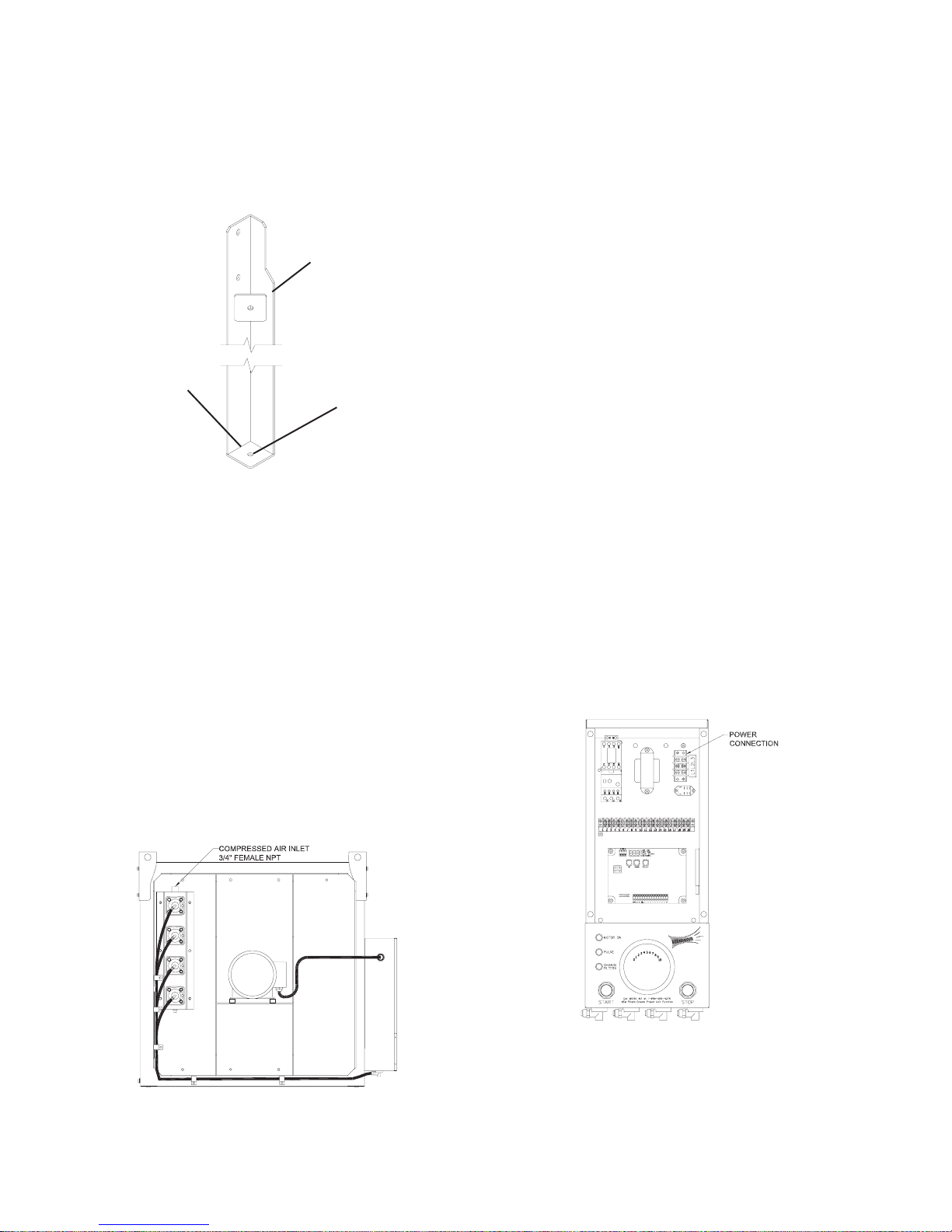
3. When the legs have been completely installed
each leg should be bolted to the ground using the
hole provided in the base plate of the leg 9see
Figure 2A).
4. After the legs have been properly anchored, the
dust containment system can be installed. (refer to
pages 9-10).
LEG
BASE PLATE
1/2” DIA. HOLE
FIGURE 2A
Compressed Air Installation
The compressed air inlet for the Roto-Pulse cleaning
system is at the top of the piping assembly located on
the backside of the unit near the blower motor (see
Figure 3). Aminimum of a 3/4 inch line and plant air
at a pressure at 80 psi is required for proper operation
of the Roto-Pulse cleaning system.
Electrical Installation
1. Remove the electrical box cover located on the
backside of the unit near the blower motor.
2. Make connections from your supply power to
terminal L1, L2, and L3. Wire size should be
rated for motor horsepower load needed for
your application (see Figure 4).
NOTE: A 7/8” diameter hole is provided for
conduit connection of supply power.
1. Connect the power. Momentarily turn the
unit on and off with the start/stop switches. Note
the rotation of the motor. Proper rotation can
be viewed at the open end of the blower motor
(remove the motor access plate if your unit has
been supplied with a motor/silencer shroud). The
proper rotation is in the clockwise direction.
NOTE: All electrical work must be done by
a qualifi ed electrician according to local and
national codes.
CAUTION: Installation can cause exposure to
live components. Disconnect electrical power
before proceeding with installation. Proper
lock out / tag out procedures should be used.
NOTE: Clean, dry, compressed air at the correct
pressure is required for the cleaning system to
operate correctly. It is recommended that a
pressure regulator and coalescing fi lter be installed
between the compressed air source and the inlet to
the dust collector.
FIGURE 3
FIGURE 4
6

4. If motor rotation is in the proper direction then
AMP draw of the motor should be checked.
Correct motor AMP draw information is
located on the inside of the Electrical Box
Cover. If motor current is higher than rated
for the motor supplied, do not continue
operation. Re-check your wiring (refer to
the inside of the electrical box cover) and if
problems continue contact your Micro-Air
Dust Collector representative for instructions.
5. Reassemble the electrical box cover onto the
enclosure.
Units Installed Outdoors
1. The remote Start/Stop Control Enclosure
supplied with the unit is not rated for outdor
use. The Control enclosure must be mounted
indoors.
2. When the enclosure is mounted, make
connection from your supply power to
terminals L1, L2, and L3. Wire size should be
rated for motor horsepower load needed for
your application (see Figure 4).
3. When power connections have been made
refer to wiring diagrams on pages 23-25 for
wiring required between the remote Start/Stop
enclosure and the Nema 4 J-box located on the
unit.
4. When supply power hase been terminated,
reconnect the power. Momentarily turn the
unit on and off with the Start/Stop switches.
Note the rotation of the motor. Proper rotation
can be viewed at the open end of the blower
motor (Remove the motor access plate if
your unit has been supplied with a motor/
silencer shroud). The proper rotation is in the
clockwise direction.
5. If the motor rotation is in the proper
direction then AMP draw of the motor
should be checked. correct motor AMP
draw information is located on the inside of
the Electrical Box Cover. If motor current
is higher than rated for the motor supplied,
do not continue operation. Re-check your
wiring (refer to the inside of the electrical box
cover) and if problems continue contact your
Micro Air Dust Collector representative for
instructions.
6. Reassemble the electrical box cover onto the
enclosure.
Unit Operation
1. Turn the unit on via the start switch located on the
side of the electrical box.
NOTE: Some particulate may pass through the
cartridge fi lters and blower upon initial start-up. This
will end once the fi lters have been seasoned and a
power cake has formed on the fi lter. If this condition
continues to occure refer to the section “Roto-Pulse
Cleaning Timer Adjustments” to increase the period
of time between pulses.
2. once the unit is running the Roto-Pulse cleaning
system will be operational. Operation is detected
by hearing a .07-second air pulse approximately
every 5 seconds. If adjustment to timing of
pulses is desired refer to the secion “Roto-Pulse
Cleaning Timer Adjustments”.
3. Check the After-Pulse Cleaning cycle by turning
off the unit via the stop switch located on the
side of the electrical box. The unit should
continue to pulse every 5 seconds for a period of
approximately 17 minutes. If adjustment to the
after-pulse time is desired, refer to the section
labeled “After-Pulse Cleaning”.
Cartridge Cleaning Operation
The Micro Air Dust Collector is designed with the
Roto-Pulse Cleaning System to clean the cartridge
fi lters.
This system provides superior cleaning performance
using a rotating tube with pre-drilled holes (see
Figure 5). As the diaphragm valve opens, the RotoPulse tube rotates while air exits the holes, thus
providing the cleaning of the cartridge.
FIGURE 5
7

1. For proper cleaning, the compressed air pressure
should be regulated at 80 psi maximum.
2. During normal operation the Roto-Pulse cleaning
system is factory set to clean two (2) cartridge
fi lters for a period of .07 seconds every 5 seconds.
3. Once the unit is turned off, the cleaning cycle
will continue for a period of 17 minutes. Do not
service the fi lters until cleaning is completed.
CAUTION: Allow 20 minutes of downtime before
opening fi lter access doors. After-Pulse system is
momentarily operational After unit is turned off.
4. The Roto-Pulse cleaning operation dislodges
particles from the cartridges. Particles then fall
down into the dust collector hopper/tray.
NOTE: When servicing the collection system, be
sure to turn the unit off.
Roto-Pulse Cleaning Timer
Adjustments
This can be adjusted from .05 seconds to 600
seconds. To adjust this time press the select
button on the timer board untill the on time
LED is lit. Press the up/down buttons untill
the desired value is displayed. Press select to
set the new value.
NOTE: While this time can be adjusted we
recommend that you leave the “ON TIME” at
the factory setting. If less cleaning is needed
you should increase the time between pulses as
means of reducing the amount of cleaning. If
more cleaning is needed you should decrease the
amount of time between pulses. Beware, as the
time between pulses is decreased for additional
cleaning, this will increase your compressed air
consumption and create an additional load on your
compressed air system.
5. once adjustments have been made replace the
electrical box cover and reconnect the power.
6. Start the unit and observe the new pulse
settings and determine if additional
adjustments are necessary. If more adjusting
is needed, repeat the previous steps.
CAUTION: Installation can cause exposure to live
components. Disconnect electrical power before
proceeding with timer adjustments. Proper lock
out / tag out procedures should be used.
1. Turn unit off via the stop switch and disconnect
power.
2. Remove the electrical box cover.
3. The timer control board is pre-set at the factory
to clean two (2) cartridge fi lters every 5 seconds.
This time can be adjusted from 1 second to 999
seconds. To adjust this time press the select button
on the timer board untill the off time LED is lit.
Press the up/down buttons untill the desired value
is displayed. Press select to set the new value.
NOTE: Cleaning of the fi lters too often will decrease
your level of performance. A certain level of dust
cake on the fi lters will improve the effi ciency of
the fi lter cartridges. You should try to maintain a
minimum of 1 in w.c. of pressure differential across
the fi lters. If you can not maintain this minimum
level of differential across the fi lters the time between
cleaning pulses should be increased until this can be
achieved.
4. The timer control board is preset at the factory
to have a cleaning pulse duration of .07 seconds.
After-Pulse Cleaning Timer
Adjustments
1. The unit is equipped with an After-Pulse
Cleaning Cycle. This cycle will continue to
clean the cartridge fi lters for a period of time
after the unit is turned off.
2. The length of the After-Pulse operation is
preset at the factory for 999 seconds (17
minutes). This time can be adjusted from 0
seconds to 999 seconds. To adjust this time
press the select button untill the off time LED
is lit. Press and hold the select button for 3
seconds. Press the up/down buttons untill the
desired value is displayed. Press select to set
the new value. The After-Pulse operation can
be disabled by setting the time value to zero
(0) seconds.
Explosion Vent Maintenance
Refer to explosion vent instructions supplied
by the vent manufacturer for information
regarding use and maintenance of the
explosion vent.
8
RP DUST COLLECTOR
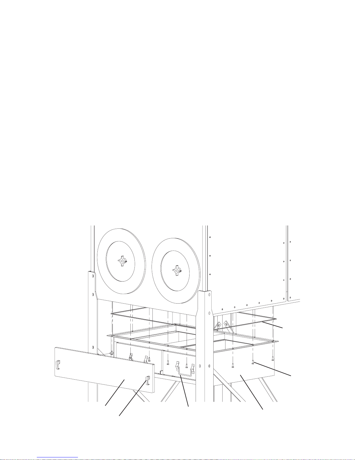
DUST COLLECTION TRAY INSTALLATION PROCEDURE
This Kit Includes:
20 ea. P3543 Self-Tapping Screws
12 ft. P3686 3/16” x 1” Self-Adhesive Foam
86 in. P1367 1” x 3/4” Foam (Placed at inside of Access Door)
1 ea. 38379-01 Dust Tray Weldment
2 ea. 38380-01 Dust Tray
1 ea. 38378-01 Dust Tray Access Door
2 ea. P1372 Door Latch
NOTE: Dust tray access door must be removed prior to assembly
INSTALLATION:
1. Apply self-adhesive foam to the bolt hole fl ange on the dust tray.
2. Align the hole pattern on the dust tray fl anges with the hole pattern on the underside ot the unit.
3. Attach the dust tray (38379-01), usting twenty (20) self-tapping screws, to the unit.
DUST TRAY ACCESS DOOR
DOOR LATCH
HANDLE
FIGURE 6
9
SELF-ADHEASIVE
FOAM
SELF-TAPPING
SCREWS
DUST TRAY WELDMENT
 Loading...