

MICRO-AIR MX3510 Installation And Operation Manual
MICRO-AIR AIR CLEANER
INSTALLATION AND OPERATION MANUAL
MX3510
Includes Installation, Operation, and Service Instructions
Read complete instructions before operating.
CAUTION
Please le for future reference.
MICRO AIR® MX3510
MX3510 MICRO AIR®
CLEAN AIR SYSTEMS
3
!
!
CLEAN AIR SYSTEMS
MODEL MX 3510 SPECIFICATIONS
Input volts: 120/208-230/460/575v, 60Hz
Max current: 20 Amps (at 120V, 1 HP, single phase)
5.2 Amps (at 208-230V, 1 HP, 3 phase)
2.6 Amps (at 460V, 1 HP, 3 phase)
6.8 Amps (at 208-230V 2 HP, 3 phase)
3.4 Amps (at 460V, 2 HP,3 phase)
9.6 Amps (at 208-230V, 3 HP, 3 phase)
4.8 Amps (at 460V,3 HP, 3 phase)
3.9 Amps (at 575V, 3 HP,3 phase)
Motor: 1 HP TEFC
2 HP TEFC
3 HP TEFC
Dimensions: 26” h X 26”w X 69”l
Shipping Wt: 300lbs
Actual Wt: 268lb*
* Add 35lbs. per charcoal module as option
PACKAGE CONTENTS
1 Ea. MX3510 Unit
1 Ea. Owners Manual
4 Ea. 5/16” X 18” Eye Bolt
4 Ea. 5/16” Hex Nut
PRE-OPERATING INSTRUCTIONS
1. After removing the cardboard packing and plastic wrap
from the unit, lay the unit down in a horizontal position.
2. Unbolt the skid from the unit. Discard skid and hardware.
HANGING INSTRUCTIONS
1. Remove the hanger kit from the owners Manual envelope
which contains four (4) threaded eyebolts and hex nuts.
2. Thread a nut onto each eyebolt and thread an eyebolt into
each of the four (4) threaded holes in the cabinet. Tighten
nuts against the cabinet. The unit is now ready to be hung
in an appropriate location.
NOTE: If hanging MX 3510 upside down is required, remove
the four (4) 5/16” hex bolts from the bottom of cabinet and
relocate to top four corners. Then place the four (4) eye bolts
into bottom panel of cabinet.
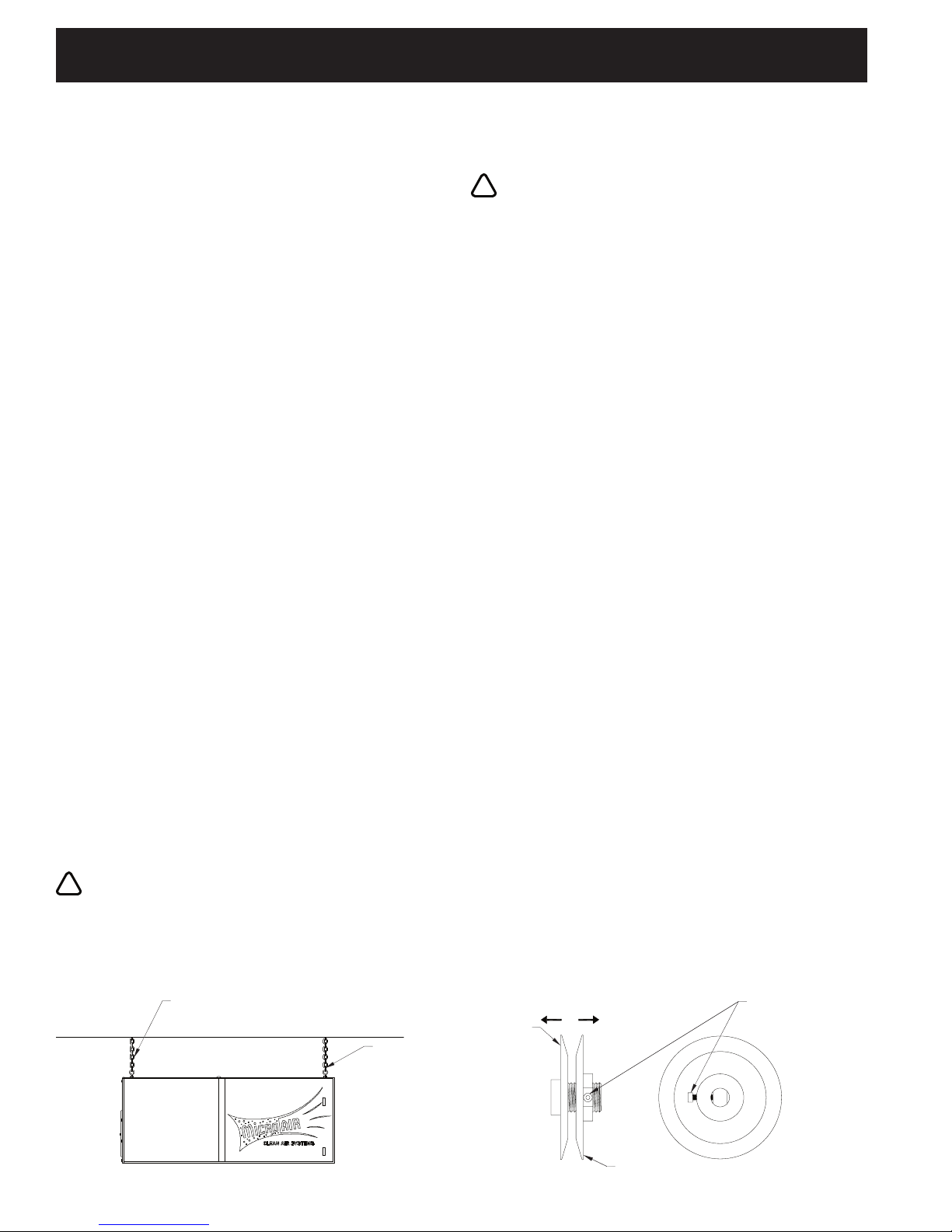
2. Once eye bolts are secured, the MX 3510 is ready to be
hung in an appropriate location. (See FIG. 1)
CAUTION: Use strong braided wire or chain to support
the aircleaner. Hang from structural supports.
NOTE: If a unit is to be installed on brackets against a wall,
use brackets strong enough to hold the unit. Install brackets
securely into the wall.
NOTE: CHAIN LINK OR CABLE. SHOULD
HANG VERTICALLY. 15° IS RECOMMENDED
MAX. ANGLE FROM VERTICAL.
EYE-BOLTS &
HEX NUTS ARE
SUPPLIED.
ELECTRICAL CONNECTIONS
1. Conduit electrical connections should be made by a
qualied electrician, and must comply with local electrical
codes.
CAUTION: Be sure that the designated circuit breaker
is off until all wiring has been completed.
NOTE: It is recommended that a properly sized motor starter /
protector be used in the supply circuit for 208-240V/460V/575V
units. 120V units have thermally protected motors with on/off
switches.
2. Make electrical connections as shown in wiring diagram to
the wires protruding form the conduit on the side of the unit.
3. Check blower for proper rotation direction. Blower should
rotate clockwise when viewed from the pulley end. If the
blower rotates backwards, interchange two of the motor
supply connections.
4. Check current draw of motor. Do not exceed Amps
specied.
PRE-OPERATION CHECKLIST
Before placing unit in service, check the following items:
• Check blower drive belt for proper tension. (Belt should
deect approximately ” when rm pressure is applied
midway between the pulleys.)
• Check that motor, blower, and drive pulleys are mounted
securely.
• Make sure that both corners of every pocket in the lter bag
is supported by the lter support rods and that lter support
rods are fully engaged in their support brackets.
• Air ow direction arrows on the pre-lters must point toward
the blower.
• Make sure that all access panels, removed during
installation, are replaced and the lter access door is
closed.
Unit is now ready to be placed in service.
AIR FLOW ADJUSTMENT
The MX 3510 is equipped with variable diameter pulleys on
the motor and blower to allow the air ow to be adjusted to the
installation requirements. The pulleys are set for maximum air
ow at the factory. The air ow rate can be reduced as follows:
1. Remove motor compartment access cover. Be careful to
avoid tearing gasket material between door and cabinet.
2. Remove belt.
3. Loosen pulley adjustment set screw on motor pulley and
screw adjustable shive out away from xed shive. Tighten
set screw onto at of xed screw (See FIG. 2).
INCREASE
DIAMETER
FIXED SHIVE
DECREASE
DIAMETER
SET SCREW TO
SET DESIRED O.D.
FIG. 1
2
FIG. 2
ADJUSTABLE SHIVE - ROTATE BY 1/2 TURN INCREMENTS
TO TIGHTEN SET SCREW AGAINST FLATS.
MX3510 MICRO AIR®
!
!
!
CLEAN AIR SYSTEMS
4. Adjusting the motor pulley may require a size larger or
smaller belt, depending on the application.
5. Replace belt and check belt tension. Proper tension should
be between ” and ” deection when belt is squeezed
with normal pressure between ngers.
6. Replace motor compartment access cover. Recheck for
correct current draw of motor.
CHANGING FILTERS
CAUTION: Always make sure that the unit is turned off
before changing lters or servicing the unit.
1. The MX3510 is equipped with a lter change light or
optional Magnehelic Gauge. If the differential pressure
has been set properly, the light or gauge signals the need
for examination of the lters.
2. When the light comes on, or gauge reads high differential
pressure, turn the unit off and remove the pre-lter only.
Replace with a new pre-lter, making sure that the air ow
directional arrow is pointed toward the outlet end. Turn the
unit back on. If the lter change light is off, or gauge reads
low differential pressure, then the unit is operating properly.
3. If the lter change light fails to go out, or the gauge
continues to read high differential pressure after replacing
the pre-lter, then the media lter also needs to be
replaced.
4. To install a new bag lter, turn the unit off. Remove the lter
from the channel and insert a new lter.
5. Start the unit. The lter change light should be off, or gauge
reads low differential pressure and the unit operating
properly.
INSTRUCTIONS FOR SIDE DISCHARGE BLOWER
EXHAUST ON MX 3510
CAUTION: Read instructions completely before
making changes.
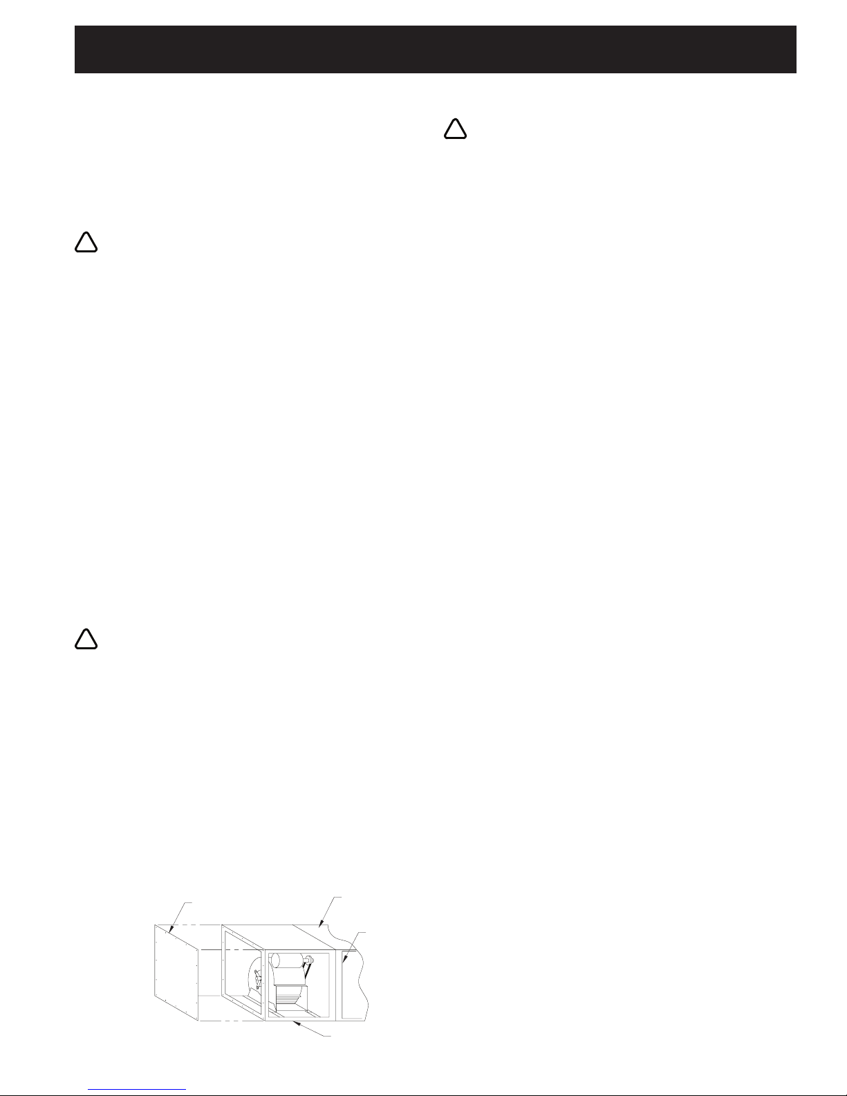
1. The MX3510 moto/blower module can be rotated so that
exhaust air exits from the side of the unit. Before rotating
motor/blower module be sure that all input power is
disconnected and unit is turned off.
2. Remove motor access door and exhaust grille.
NOTE: Care is required when removing the panel to protect the
blower outlet gasket.
3. Remove 15⁄16” hex bolts and washers that secure motor/
blower module to lter module.
4. Rotate motor/blower module 90° as shown in FIG. 3.
5. Using 15⁄16” hex bolts and washers re-secure motor/blower
module with lter module.
CAUTION: Due to relocation of internal components,
some wiring may be loose. Be sure to retain wires so
they will not become loose in air stream of blower inlet.
6. Reinstall motor access door and exhaust grille.
NOTE: Care is required to protect blower outlet gasket.
7. Reconnect input power and turn unit on. Check for proper
air ow and blower rotations
PRESSURE SWITCH ADJUSTMENT INSTRUCTIONS
1. The pressure switch which turns the light on with a
differential pressure increase, should be wired to poles L1
(red) and L2 (blue) at the time of installation with 208/230/
460 volt source. (See Wiring Diagram.)
2. The pressure switch is preset at the factory to indicate (light
on) dirty lters, but may need readjustment due to a desire
for earlier or later lter changes, a different combination
of lters, or because the set point shifted during shipping.
The pressure switch is also orientation sensitive. To
readjust the switch, remove the hole plug in the side of the
unit for access to the adjustment screw. Make sure lters
and pre-lters are installed in unit. Turn the unit on and
place a piece of cardboard over the intake covering about
80 to 85% of the intake area. With a standard screwdriver,
turn the adjustment screw clockwise until the light goes off,
or counterclockwise until the light comes on.
3. For more time between lter changes (less air ow), cover
slightly more of the opening, and for less time between lter
changes (more air ow), cover less of the opening.
GENERAL MAINTENANCE
1. Occasionally check the condition of the drive belt for
tightness and wear.
2. Check the blower bearings for unusual war and the blower
wheel for debris and dirt. Clean when necessary.
3. Check the wiring for loose connections or cracked
insulation.
4. No lubrication is required for the motor because it is a
permanent pre-lube design. Excessive dirt and or oil
should be removed periodically.
MOTOR ACCESS
DOOR
FIG. 3
FILTER MODULE
FILTER DOOR
BLOWER MODULE
3
MICRO AIR® MX3510
MX3510 MICRO AIR®
CLEAN AIR SYSTEMS
5
CLEAN AIR SYSTEMS
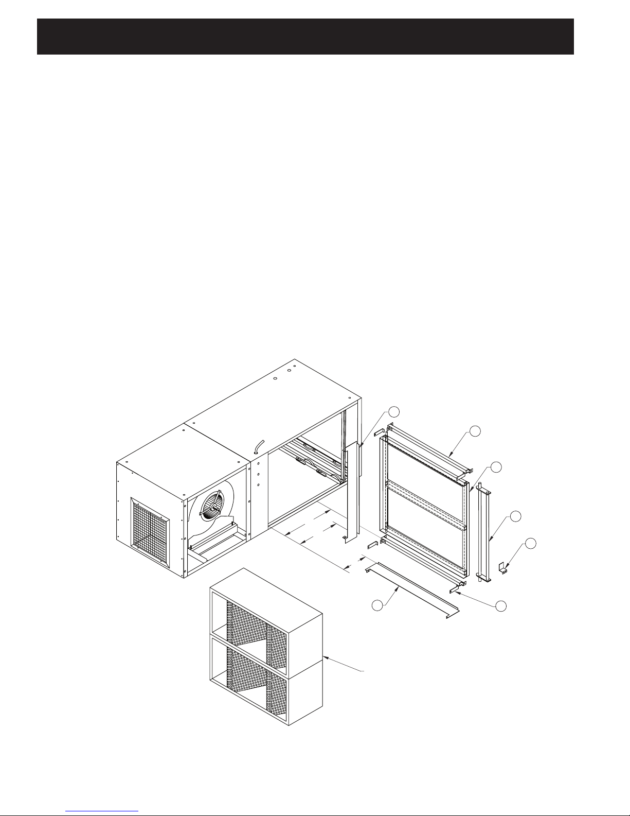
UNITS WITH HEPA OR CHARCOAL OPTIONS FOR
MX3510
1. On units with optional HEPA or charcoal lters, an adjustable lter
track kit is used to complete the seal of these lters to the lter
stop (See FIG. 4 & 5). If the unit was ordered with either a HEPA
or charcoal lter, this adjustable lter track kit was included with
the unit. If a HEPA or charcoal lter is ordered as an after-market
item, the adjustable ler track kit should be ordered as well. Order
Part No. 38036-01.
Each lter track kit is supplied with:
j 1pc. Filter track
k 2pc. Supports
l 1pc. Handle
m 4pc. Retaining brackets
n 1pc. Door stop bracket
o 3pc. Horizontal support
p 16pc. #8-32 self tapping hex screws.
HEPA OR CHARCOAL AS SECOND MAIN FILTER
1. Place supports k in cabinet at a dimension of 13 ” and
secure with self tapping screw.
2. Place track j in cabinet so it rests upon supports and ”
diameter pin is located behind brackets on supports.
3. Place handle l on supports so that it rests in notches.
4. Lock ” diameter rods on handle and track in place with
brackets m and self tapping screws.
5. Place handle stop bracket n at a dimension of 15 ” and
secure with self tapping screws. This is to keep handle
from rotating past 90° and allowing lter to loosen.
6. Place horizontal supports o in 2 places. One piece at
a dimension of 5” on bottom of cabinet and one piece at
a dimension of 10” on rear of cabinet with self tapping
screws.
13”
10”
6
2
TYP. 2 PLCS.
1
3
5
5”
6
RCM
4
TYP. 4 PLCS.
FIG. 4
4
 Loading...