


EasyTouch
Operation Manual
2.5” Color TFT Touch Screen Controller
for FX1 & FX2 Control Boards
Micro-Air, Inc. www.microair.net
124 Route 526 Ph: (609) 259-2636
Allentown, NJ 08501 Fax: (609) 259-6601

TABLE OF CONTENTS
1. INTRODUCTION .................................................................................................................. 4
2. READ THIS MANUAL BEFORE PROCEEDING ................................................................ 4
3. FEATURES .......................................................................................................................... 4
3.1 Standard ..................................................................................................................................................... 4
3.2 Optional ...................................................................................................................................................... 4
3.3 Control Boards and Options Supported by EasyTouch ............................................................................. 5
4. OVERVIEW .......................................................................................................................... 6
4.1 EasyTouch Home & Main Screen Displays ............................................................................................... 6
4.2 EasyTouch Power-Up & Default Sleep Mode Screen Display ................................................................... 6
5. INSTALLING THE DISPLAY PANEL .................................................................................. 6
5.1 Choosing the Location ................................................................................................................................ 6
5.2 Installing the Battery (for older EasyTouch models only) ........................................................................... 6
5.3 Mounting the Display .................................................................................................................................. 7
6. INSTALLING THE OPTIONAL SENSORS .......................................................................... 8
6.1 Remote (Alternate) Air Temperature Sensor ............................................................................................. 8
6.2 Outside Air Temperature Sensor................................................................................................................ 8
6.3 Service Sensor (for DX systems only) ....................................................................................................... 8
6.4 Water Inlet Temperature Sensor (for CW systems only) ........................................................................... 8
6.5 Combination Temp/Humidity Sensors (for CW & FAMU FX2 systems only) ............................................. 9
7. NORMAL HEATING OR COOLING CYCLE ....................................................................... 9
7.1 Reversing Valve Operation (for DX systems only) ..................................................................................... 9
7.2 Water Valve Operation (for CW systems only) .......................................................................................... 9
8. STANDARD OPERATION ................................................................................................. 10
8.1 Operator Controls and Display ................................................................................................................. 10
8.2 Modes of Operation .................................................................................................................................. 12
8.3 Fan Speed Modes .................................................................................................................................... 13
9. FRESH AIR MAKEUP (FAMU) OPERATION ................................................................... 14
9.1 FAMU Operator Controls and Display ...................................................................................................... 15
9.2 FAMU Sequence of Operation ................................................................................................................. 16
9.3 FAMU Settings & Recommendations ....................................................................................................... 18
10. FAULTS ............................................................................................................................. 18
10.1 Air Sensor Fault (DX & CW, immediate lockout)...................................................................................... 19
10.2 FAMU Sensor Faults (FAMU only, immediate lockout) ........................................................................... 19
10.3 High Pressure Fault (DX & FAMU DX only, contributes to lockout count) ............................................... 19
10.4 Low Pressure Fault (DX & FAMU DX only, contributes to lockout count) ............................................... 19
10.5 Low AC Fault (DX & FAMU DX only, no lockout)..................................................................................... 20
10.6 Pump Sentry Fault (DX & FAMU DX only, contributes to lockout count) ................................................. 20
10.7 Overcurrent Fault (DX & FAMU DX only, contributes to lockout count)................................................... 20
10.8 Lost AC Fault (DX & FAMU DX Only, no lockout).................................................................................... 20
10.9 EasyStart Fault (DX & FAMU DX only, contributes to lockout count) ...................................................... 21
11. MENU AND SETTINGS OVERVIEW ................................................................................. 21
11.1 Menu Screen ............................................................................................................................................ 21
11.2 Settings Screen ........................................................................................................................................ 22
12. CONTROL PARAMETERS MENU .................................................................................... 22
12.1 General Settings ....................................................................................................................................... 23
12.2 Fan Speed Settings .................................................................................................................................. 30
12.3 DX Operational Settings ........................................................................................................................... 32
12.4 CW Operational Settings .......................................................................................................................... 36
12.5 FAMU DX Operational Settings................................................................................................................ 37
12.6 FAMU CW Operational Settings............................................................................................................... 38
Micro-Air, Inc. Page 2 EasyTouch Operations Manual
Rev 3.0 4/3/17

12.7 Memorize Settings .................................................................................................................................... 39
12.8 Recall Memorized Settings ....................................................................................................................... 39
12.9 Recall Default Settings ............................................................................................................................. 40
13. PROGRAM SCHEDULER MENU ...................................................................................... 40
13.1 Mode Control and Operational Behaviors ................................................................................................ 40
13.2 Programming a Day or Group of Days ..................................................................................................... 41
14. DATE/TIME MENU ............................................................................................................ 41
14.1 Enabling the Date/Time Display ............................................................................................................... 42
14.2 Changing the Date/Time Format .............................................................................................................. 42
14.3 Setting the Date & Time ........................................................................................................................... 42
15. SYSTEM MENU ................................................................................................................. 43
15.1 Firmware Version ..................................................................................................................................... 43
15.2 Display Setup ........................................................................................................................................... 43
15.3 Sleep Mode Settings ................................................................................................................................ 44
15.4 Display Lock ............................................................................................................................................. 45
15.5 Cleaning Mode ......................................................................................................................................... 47
15.6 Wi-Fi Settings (optional EasyTouch feature) ............................................................................................ 47
16. TROUBLESHOOT & COMMISSION MENU ...................................................................... 48
16.1 System Status .......................................................................................................................................... 49
16.2 Help & Information .................................................................................................................................... 49
16.3 Commission Procedure ............................................................................................................................ 49
17. FAULT HISTORY & RUN HOURS MENU ......................................................................... 50
17.1 Fault History ............................................................................................................................................. 50
17.2 Compressor Run Hours ............................................................................................................................ 51
17.3 Fan Run Hours ......................................................................................................................................... 51
18. SPECIFICATIONS ............................................................................................................. 52
19. WARRANTY AGREEMENT .............................................................................................. 53
Micro-Air, Inc. Page 3 EasyTouch Operations Manual
Rev 3.0 4/3/17

1. INTRODUCTION
The EasyTouch Control is a microcontroller-based unit designed for use with direct expansion, reversecycle air conditioning systems or with chilled-water air handlers.
2. READ THIS MANUAL BEFORE PROCEEDING
Read this manual completely before you proceed with the installation and operation of the EasyTouch. If
you have questions or require assistance with your EasyTouch control, contact Micro-Air at +1 (609) 259-
2636.
The EasyTouch is covered under the Micro-Air Warranty Policy, and incorrect installation, neglect and
system abuse are not covered under warranty policy. See section 19 for more details.
3. FEATURES
3.1 Standard
Works automatically via auto-detection with FX1 or FX2 control circuit boards.
User-friendly and intuitive 2.5” touch screen display requires no manual for basic operation.
Five-volt logic and microcontroller located in the display.
Automatic and three programmable manual fan speeds.
Numerous programmable parameters for custom installations.
Moisture Mode for controlling relative humidity.
De-Icing cycle to prevent evaporator coil icing.
Programmable compressor staging delays.
Universal 115-230V, 50/60Hz AC power supply.
Nonvolatile memory retains settings without batteries.
Programmable display-brightness control.
Programmable failsafe modes.
Integrated CAN-bus network capability
Low-Voltage Monitor.
AC Current Monitor
Fits Vimar® Eikon and Eikon EVO bezels.
3.2 Optional
Outside air temperature sensor.
Alternate air temperature sensor.
Pump Sentry (Service) water sensor.
Combination Temp/%RH sensor for Cabin Relative Humidity Control in CW
Electric heating control capabilities in reverse-cycle DX and in CW.
Air Filter Cleaning or Replacement Timer.
Fresh Air Makeup (FAMU) DX and CW Control
Expanded 4x DC Blower Output (daughterboard) support
EasyStart Soft Starter (daughterboard) support
Wi-Fi support for EasyTouch smart phone application
Micro-Air, Inc. Page 4 EasyTouch Operations Manual
Rev 3.0 4/3/17
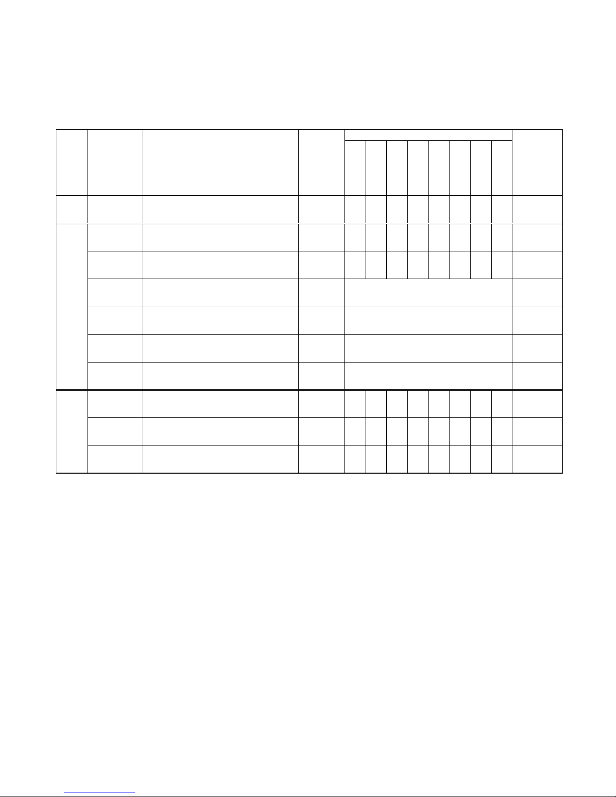
3.3 Control Boards and Options Supported by EasyTouch
Standard
Cabin %RH
FAMU
AC Current
Limit
CAN Bus
EasyStart
DC Blower
Wi-Fi
FX1 ASY-370-X09
FX1 Control Board, standard All
Any
ASY-360-XG1
FX2 Control Board, standard G1 and older
Any
ASY-360-XG11
FX2 Control Board, with 731 Temp/Humidity
Sensor Daughterboard Option (depopulated)
G1
N05 or newer
ASY-360-XG2
FX2 Control Board, with 361 CAN Bus
Daughterboard Option
n/a n/a
ASY-360-XG4
FX2 Control Board, with 361 Expanded
DC Blower Daughterboard Option
n/a n/a
ASY-360-XG5
FX2 Control Board, with 367 EasyStart™
Daughterboard Option
n/a n/a
ASY-360-XG8
FX2 Control Board, with 731 FAMU
Daughterboard Option
n/a n/a
ASY-360-XL1/3
FX2 Control Board, standard w/ Integrated
CAN Bus Support
J and newer
1
1
N07 or newer
N10 for Wi-Fi
ASY-360-XL4
FX2 Control Board, with 361 Expanded
DC Blower Daughterboard Option
J and newer
4
2
N07 or newer
N10 for Wi-Fi
ASY-360-XL4/5
FX2 Control Board, with 521 EasyStart™
Daughterboard Option
J and newer
1
1
N07 or newer
N10 for Wi-Fi
FX2
1st Gen
FX2
2nd Gen
Not Supported
Not Supported
Not Supported
Not Supported
Required
EasyTouch
Firmware
Version
Control
Family
Control Board
Micro-Air P/N
Control Board Description
Control
Board
Hardware
Versions
Supported Control Features
The EasyTouch has evolved and supports all of the features available in the original FX1 and in the
newest FX2 Control Boards. Please refer to the following chart below for the minimum required
firmware versions for the EasyTouch to support the control features required.
Table 1 – Control Boards & Options Supported by EasyTouch
1
One DC Blower output is integrated into base control board, and can support up to 2 DC blowers in
parallel
2
Four separate DC blower outputs are available on the daughterboard with individual fan speed
programming. The one DC blower output integrated into the base control board can still be used
and its speed settings follow that of Fan A.
This manual provides all necessary information for proper installation and operation of the
EasyTouch Display. Poor installation and misunderstood operating parameters will result in
unsatisfactory performance and possible failure.
Micro-Air, Inc. Page 5 EasyTouch Operations Manual
Rev 3.0 4/3/17

4. OVERVIEW
4.1 EasyTouch Home & Main Screen Displays
The EasyTouch Home screen shown in Figure 1 consists of large, easy to read graphics, with large
buttons for basic control functions. The Main screen shown in Figure 2 consists of smaller graphics
showing all of the controls readouts and statuses, and had more buttons for all of the control
functions.
Figure 1 – Home Screen Display Figure 2 – Main Screen Display
4.2 EasyTouch Power-Up & Default Sleep Mode Screen Display
During power up and whenever the display enters Sleep Mode, the display shown in Figure 3 is
shown. While in Sleep mode, the graphic will move around the screen. See section 15.3 for more
information on the various Sleep Mode settings.
Figure 3 – Power-Up & Default Sleep Screen Display
5. INSTALLING THE DISPLAY PANEL
5.1 Choosing the Location
Before mounting the control panel, consider the location. The display panel’s built-in air sensor
provides excellent room-air temperature sensing when properly located and installed. The physical
location of the air sensor is shown in Figure 4 and marked with “S”. Be sure to mount the display
panel on an inside wall, slightly higher than mid-height of the cabin, in a location with freely circulating
air where it can best sense average temperature. The display’s distance from the air conditioner must
be within the 15’ (4.5m) length of the display cable. Longer, custom cable lengths are also available.
5.2 Installing the Battery (for older EasyTouch models only)
Starting in second half of 2015, all EasyTouch display will be supplied with a rechargeable battery
that requires no installation or maintenance. Previous models will be supplied with a loose type
CR2032 battery that must be installed before mounting the display. The purpose of this battery is to
maintain the time clock and date calendar only whenever AC power is removed from the EasyTouch.
The battery has nothing to do with numerous programmable settings and features of EasyTouch, all
of which are stored in non-volatile memory that does not require a battery.
Micro-Air, Inc. Page 6 EasyTouch Operations Manual
Rev 3.0 4/3/17

S
Figure 4 – EasyTouch Display Front Panel
IMPORTANT:
Do not mount the display in direct sunlight, near any heat-producing appliances or in a
bulkhead where temperatures radiating from behind the panel may affect performance. Do
not mount the display in the supply-air stream. Do not mount the display above or
below a supply-air or return-air grille. Do not mount the display behind a door, in a corner,
under a stairwell or any place where there is no freely circulating air. If you cannot mount
the display in a suitable location for accurately sensing room temperature, install the
optional remote air sensor as explained in section 6.1.
5.3 Mounting the Display
1. Choose a wall location that has adequate depth (at least 1”/25.4mm) behind the wall itself. See
Figure 5 for the depth dimensions of the display.
2. Make the cut-out for the display panel as shown in Figure 6. Cut-out size is 2.900” (74mm) wide
by 2.165” (55mm) tall.
Micro-Air, Inc. Page 7 EasyTouch Operations Manual
Rev 3.0 4/3/17
Figure 5 – EasyTouch Display Top View Mounting Dimensions

Figure 6 – EasyTouch Display Mounting Dimensions
3. Plug one end of the display cable (8-pin connector) into the display jack on the circuit board in the
electric box and the other end into the back of the display panel.
4. Secure the display panel to the bulkhead using the four screws provided.
Do not use a screw gun and do not over tighten screws when mounting, because either method
may damage the display.
5. When the display is securely mounted, mount the bezel over the display frame until it snaps into
place.
6. INSTALLING THE OPTIONAL SENSORS
6.1 Remote (Alternate) Air Temperature Sensor
Install the optional remote air sensor if the display cannot be mounted in a proper location for
accurately sensing room temperature. Installing the remote air sensor overrides the display’s built-in
sensor. The standard cable length for the remote air sensor is 7 feet (2.1m).
1. Mount the remote air sensor in a reliable return-air stream, preferably just behind the opening of
the return-air grille. DO NOT attach the sensor to the edge of the unit’s drain pan since the
condensate water and cold air spilling off of the heat exchanger coil will cause an inaccurate
temperature reading.
2. Plug its cable (6-pin connector) into the “ALT. AIR” or “ALT. AIR / RH” jack on the circuit board.
6.2 Outside Air Temperature Sensor
Install the optional outside air temperature sensor to monitor the temperature outside the cabin.
Outside air sensor cables are available in various lengths.
1. Mount the sensor outside but not in direct sunlight.
2. Plug its cable into the “OAT” jack on the circuit board.
6.3 Service Sensor (for DX systems only)
Install the optional condenser coil temperature sensor into the “OAT/H20” jack on the FX1 circuit
board or into the “SERVICE” header on the FX2 circuit board.
1. Mount the sensor in the middle of the condenser coil, strapping it securely to the piping.
2. Enabled the use of this sensor by going to DX Operational Settings, and then the Pump Sentry
feature as explained in section 12.3.5.
6.4 Water Inlet Temperature Sensor (for CW systems only)
When using the EasyTouch with a chilled-water air handler, plug the water-inlet sensor cable into the
“OAT/H2O” jack on FX1 or into the “OUTSIDE / RH” jack on FX2. Attach the sensor securely to the
Micro-Air, Inc. Page 8 EasyTouch Operations Manual
Rev 3.0 4/3/17

chilled-water inlet pipe on the air handler. Ensure that the sensor makes good contact with the
copper pipe and make sure it is covered with adequate insulation. DO NOT attach the sensor to
rubber hose.
6.5 Combination Temp/Humidity Sensors (for CW & FAMU FX2 systems only)
As described in the table in section 3.3, the EasyTouch supports an optional temperature and relative
humidity sensor for cabin %RH control and for Fresh Air Makeup (FAMU) operation on FX2 control
boards only. For FX2 control boards with hardware revision is available only with the FX2 control
board. For FX2 control board rev J and newer, plug the combo temperature/humidity sensor into the
“ALT. AIR / RH” jack for cabin %RH control, and plug in an additional combo temperature/humidity
sensor into the “OUTSIDE / RH” jack for FAMU control operation. For FX2 control board revisions G1
and older, the optional Temp/Humidity Sensor daughterboard is required to support cabin %RH
control only; plug the combo temperature/humidity sensor into the “INTAKE” jack on the
daughterboard and insure that the Inside Temp Sensor Selection programming parameter is set to
“AUTO” (see section 12.1.16).
The cabin temperature and humidity control feature is enabled automatically once a combo
temperature/humidity sensor is detected in either the “ALT. AIR / RH” or “INTAKE” jacks on the FX2
board revisions described above. See section 12.1.11 for more information on using the humidity
control feature.
The FAMU control feature must be deliberately enabled in order to take effect. See section 9 for
more information on setting up FAMU control operation.
7. NORMAL HEATING OR COOLING CYCLE
In Automatic Mode, heating and cooling are supplied as required. If cooling is required, the system will
start a cooling cycle when the cabin temperature exceeds the set point by 2°F (1.0°C) and will continue to
cool until the temperature equals the set point. (See the parameter setting Set Point Temperature
Differential as described in section 12.1.3 for more information on how to change this variation to 1°F
[0.5°C].) The cabin temperature must drop below the set point by at least 4°F (2.0°C) in order for the
system to switch from cooling to heating. Similarly, if heating is required, the system will start a heating
cycle when the cabin temperature is below the set point by 2°F (1.0°C) and will continue to heat until the
temperature equals the set point. The cabin temperature must exceed the set point by at least 4°F (2.0°C)
in order for the system to switch from heating to cooling. If you select Cool Mode, only cooling is supplied.
If you select Heat Mode, only heating is supplied. The cabin temperature in either mode is maintained
within 2°F (1.0°C) of set point by default. When the heating or cooling set point is satisfied, the compressor
cycles off and the fan returns to low speed. The fan speed remains constant if Manual Fan Speed is
selected. For more information on the fan speed control and its operation, see section 8.3.
7.1 Reversing Valve Operation (for DX systems only)
The position of the reversing valve determines if the system is in Cool Mode or Heat Mode. The
EasyTouch and FX1/FX2 systems are designed to energize the reversing valve output when in
Heat Mode. In addition, the reversing valve will toggle into the opposite position for 2 seconds to
equalize the system pressure and reduce the compressor’s starting surge whenever a cooling or
heating cycle is called for and the system has been off for less than 75 seconds. Unnecessary valve
toggling is limited to reduce reversing valve noise.
7.2 Water Valve Operation (for CW systems only)
When cooling or heating is required, the water valve will not open unless the water temperature is
adequate. The fan remains in low speed until the adequate water temperature is available and the
system status on the Main display screen will show “Cool Pending” or “Heat Pending”. If the optional
Electric Heater is enabled, heating will be provided if the water temperature is not adequate. See the
Water Temperature Differential parameter setting described in section 12.4.2 for a definition of
adequate cooling or heating water temperature and how to adjust its factory default setting to
something other than 10°F (6°C).
Micro-Air, Inc. Page 9 EasyTouch Operations Manual
Rev 3.0 4/3/17

8. STANDARD OPERATION
6
7 8 1 2 3 4 5
9
8.1 Operator Controls and Display
8.1.1 Home Screen Indicators & Buttons
Figure 7 – EasyTouch Home Screen Icons & Functions
1. Force Sleep Mode Button - Press and release to force Sleep Mode to initiate
immediately, if enabled. See section 15.3 for more information on Sleep Mode.
2. Temperature Display Selection – Indicates the current temperature display value: SET,
INSIDE, OUTSIDE, SERVICE/WATER, or %RH. If the associated temperature sensor is
not installed or is faulty, “- - -” will be displayed.
3. Status Indicator – This display area indicates the abbreviated operational status of the
control, including standby and active states, fault states, fault recovery, and fault lockout.
More information on the operational status is available on the Main Screen.
4. Temperature Display Indicator – This value indicates the current temperature reading
that corresponds to the Temperature Display Selection explained above. Press and
release over the top of the numeric value to select the various temperature displays: Set
point(s), Inside, Outside, Service/Water temperatures, or Relative Humidity (if equipped).
By default, the temperature display will always revert back to showing the Inside
Temperature after 3 seconds. If you wish to change the default Temperature Display to
one of the other available choices, immediately after selecting the desired temperature,
press and hold again for 5 seconds (until the button highlight disappears) and the
currently displayed temperature will be retained and reverted back to.
5. More Button - Press and release to change display to Main Screen.
6. Up Button - Press and release to display the set point. Press and release or press and
hold the UP button to increase the set point.
7. Down Button - Press and release to display the set point. Press and release or press
and hold to decrease the set point.
8. Power On/Off Button - Press and release to toggle between the ON (green) and OFF
(red) operation.
9. Wi-Fi Network Status Indicator Icon – If the EasyTouch display has the optional Wi-Fi
support feature installed, a Wi-Fi icon will appear and indicate the status of the Wi-Fi
connection. Green=connected, Yellow=connecting in progress, and Red=connection
failed/disconnected.
Micro-Air, Inc. Page 10 EasyTouch Operations Manual
Rev 3.0 4/3/17

8.1.2 Main Screen Indicators & Buttons
12
11
14
15
13 6 7 8 9
10 1 2
3
4 5 16
Figure 8 – EasyTouch Main Screen Icons & Functions
1. Mode Button - The Mode button indicates the currently active mode of operation. Press
and release to step through the four available operating modes: COOL, HEAT, AUTO,
and MOISTURE. See section 8.2 for more information on all the modes of operation.
2. Fan Speed Mode Indicator – This label indicates the current fan speed mode, AUTO or
MANUAL. See section 8.3 for more information on the fan speed mode.
3. Fan Speed Indicator – This indicator is a bar graph that shows the speed at which the
fan is currently operating. There are 3 fan speeds with EasyTouch: 1 bar lit indicates low
speed, 4 bars lit indicate medium speed, and 7 bars lit indicate high speed.
4. Fan Button – The Fan button is used to control the fan speed. The Fan button will rotate
when the fan is on, and will be stationary when the fan is off. See section 8.3 for more
information on the controlling the fan speed.
5. Menu Button – The Menu button allows access to the EasyTouch Main Menu and all
sub-menus beyond. See section 11 for more information on the menus.
6. Up Button - Press and release to display the set point. Press and release or press and
hold the UP button to increase the set point.
7. Temperature Display Selection – Indicates the current temperature display value: SET,
INSIDE, OUTSIDE, SERVICE/WATER, or %RH. If the associated temperature sensor is
not installed or is faulty, “- - -” will be displayed.
8. Temperature Display Indicator – This value indicates the current temperature reading
that corresponds to the Temperature Display Selection explained above. Press and
release over the top of the numeric value to select the various temperature displays: Set
point(s), Inside, Outside, Service/Water temperatures, or Relative Humidity (if equipped).
By default, the temperature display will always revert back to showing the Inside
Temperature after 3 seconds. If you wish to change the default Temperature Display to
one of the other available choices, immediately after selecting the desired temperature,
press and hold again for 5 seconds (until the button highlight disappears) and the
currently displayed temperature will be retained and reverted back to.
9. Down Button - Press and release to display the set point. Press and release or press
and hold to decrease the set point.
Micro-Air, Inc. Page 11 EasyTouch Operations Manual
Rev 3.0 4/3/17

10. Power On/Off Button - Press and release to toggle between the ON (green) and OFF
(red) operation.
11. Date & Time Display – The date and time are displayed here, if enabled. See section
14 for information on how to set the date & time, change formats, and enable or disable
the display.
12. Home Button – Hidden behind the Micro-Air logo is a button that when pressed returns
the display to the Home Screen.
13. Operational Status & Fault Help Button – This display area indicates the current
operational status of the control, including standby and active states, fault states, fault
recovery, and fault lockout. If a fault is active, touching this status area will display the
Fault Help screen for the active fault. See section 9.3.2 for more information on fault
displays.
14. Program Scheduler Status and Resume Button – This display area indicates the
current operational status of the Program Scheduler. If the Program Scheduler is
currently in an Override state, touching this status area will cause the Program Scheduler
to resume the active program for the current time & date period. See section 13 for more
information on the Program Scheduler.
15. Filter Maintenance Status – If enabled, this display area indicates when it is time to
clean or replace the air filter. See section 12.1.6 for more information on the Air Filter
Reminder.
16. Wi-Fi Network Status Indicator Icon – If the EasyTouch display has the optional Wi-Fi
support feature installed, a Wi-Fi icon will appear and indicate the status of the Wi-Fi
connection. Green=connected, Yellow=connecting in progress, and Red=connection
failed/disconnected.
8.2 Modes of Operation
8.2.1 OFF Mode
When the control is in OFF Mode, all control outputs are turned off. Upon entering OFF
mode, if the electric heater was active within the previous 4 minutes, the fan will remain on at
low speed for up to 4 additional minutes to cool down the electric heater.
8.2.2 ON Mode
When the control is in ON Mode, power is supplied to the appropriate outputs and the display
indicates the current state of operation.
8.2.3 AUTO Mode
When AUTO Mode is selected as indicated by the Mode button icon, the system provides
both heating and cooling as required. The Inside temperature in is maintained within 2°F (or
1.0°C) of set point by default. See section 12.1.3 for more information on the Set Point
Temperature Differential parameter setting and how it can be adjusted. If the system was
most recently cooling, the cabin temperature must drop below the set point by at least 4°F (or
2.0°C) by default in order for the system to switch from cooling to heating. Similarly, if the
system was most recently heating, the cabin temperature must exceed the set point by at
least 4°F (or 2.0°C) by default in order for the system to switch from heating to cooling. This
behavior prevents small temperature overshoots from causing the system to switch between
heating and cooling when it is not necessary.
8.2.4 COOL Mode
When COOL Mode is selected as indicated by the Mode Button icon, only the cooling system
operates as required. If the ambient temperature drops below the set point, the system will
not automatically switch to the HEAT Mode.
8.2.5 HEAT Mode
When HEAT Mode is selected as indicated by the Mode Button icon, only the heating system
operates as required. If the ambient temperature rises above the set point, the system will not
automatically switch to the COOL Mode.
8.2.6 MOISTURE Mode
MOISTURE Mode, sometimes called “Humidity” or “Dehumidification” mode, is used to help
control humidity while you are away from the boat or away from a particular cabin. Once
Micro-Air, Inc. Page 12 EasyTouch Operations Manual
Rev 3.0 4/3/17

MOISTURE Mode is enabled as indicated by the Mode Button Icon, the fan circulates the air
for 30 minutes. During this time, the air temperature is sampled and entered into memory.
After 30 minutes, a cooling cycle starts and continues until the temperature is lowered 2°F (or
1.0°C) or until the cooling cycle runs a maximum of one hour. Four hours after the
temperature is satisfied or the cooling cycle times out, this cycle repeats. Moisture Mode will
also prevent your boat or a particular cabin from dropping below a minimum temperature as a
means to prevent the contents from freezing. When the temperature drops low, eliminating
moisture may become less of a concern and maintaining some minimum temperature may
become more important. After the 30-minute fan circulation, if the temperature is at or above
the Humidity Mode Minimum Temp (50°F/10°C, by default), a cooling cycle is started and
runs as described above. However, if the temperature is below the Humidity Mode Minimum
Temp, a heating cycle will be started instead. The heating cycle will continue until the
temperature reaches the Humidity Mode Minimum Temp or until the heating cycle runs a
maximum of one hour. Four hours after the temperature is satisfied or the cooling/heating
cycle times out, the entire cycle repeats, each time determining whether cooling or heating is
required. See section 12.1.11 for more information on how to adjust the Humidity Mode
Minimum Temp parameter setting to a temperature that may better suit your particular
requirements.
IMPORTANT (for DX systems only):
If your air conditioning unit is Cool-Only (i.e. it does not have a reversing valve) and an
Electric Heater is not installed or enabled, then COOL Mode MUST be selected. DO NOT
use AUTO or HEAT modes for a Cool-Only unit. If either AUTO or HEAT modes are selected
with a Cool-only unit and the thermostat calls for heating, the compressor will run and still
provide cooling.
8.3 Fan Speed Modes
8.3.1 Automatic Fan Speed Mode
EasyTouch has three automatic fan speeds available: High, Medium and Low. While in the
On Mode, Automatic Fan Speed Mode allows the EasyTouch to determine the required fan
speed based upon the set point temperature differential. This permits a balance between the
most efficient temperature control and slower, quieter fan speeds. To select Automatic Fan
Speed Mode, on the Main Screen press and release the Fan Button as many times as
necessary until the word “AUTO” is displayed above the fan speed bar graph.
8.3.2 Manual Fan Speed Mode
There are three manual fan speeds available: High, Medium and Low. While in the On Mode,
Manual Fan Speed Mode allows you to select and maintain a desired fan speed. To select
Manual Fan Speed Mode, on the Main Screen press and release the Fan Button until the
desired speed is indicated on the Fan Speed bar graph and the word “MANUAL” is displayed
above the fan speed bar graph. The selected fan speed will increase and decrease as the
Fan Button is repeatedly pressed until the Fan Speed Mode is returned back to Automatic.
8.3.3 Fan-Only Mode
While in the Off Mode, use the Fan-Only Mode to operate the fan for air circulation when no
cooling or heating is desired. On the Main Screen, press and release the Fan Button to start
at low fan speed. Press and release again to select Medium fan speed. Press and release a
third time to select High fan speed. Press and release a fourth time to turn off the fan. Putting
the control into ON Mode will cancel the Fan-Only Mode and revert the fan speed back to the
Automatic Mode or whatever the last selected manual fan setting was.
NOTE: Please refer to section 12.1.11 for more information on the Fan Operational Modes,
Continuous or Cycled.
Micro-Air, Inc. Page 13 EasyTouch Operations Manual
Rev 3.0 4/3/17

9. FRESH AIR MAKEUP (FAMU) OPERATION
A Fresh Air Makeup (FAMU) system is meant to draw in and condition outside air and drive it into the
interior cabin areas. The air drawn in from the outside is considered the “intake”, and the air discharged
into the cabin is considered the “exhaust”. The FAMU unit must condition the outside air in a single pass
through the system. FAMU systems therefore must incorporate both cooling and electric heating.
EasyTouch supports FAMU operation for both DX and CW systems using the FX2 Control Board, rev J and
newer. Please refer to the FX2 Control Board User Manual for further details on how to wire the FX2
control board to a FAMU system (available on the Micro-Air website at this link).
A FAMU system takes warm and moist intake air at temperature T1, dew point DP1, and relative humidity
%RH1, and will first cool and dry the air to a lower dew point DP2 at a temperature lower than the desired
exhaust set point. Then, the FAMU system will reheat the air, increasing only its dry bulb temperature,
further reducing its relative humidity, to temperature T2 and relative humidity %RH2. Please refer chart
shown in Figure 9 for a Psychrometric analysis and overview of how a FAMU system accomplished this
function.
Figure 9 – Fresh Air Makeup (FAMU) Operation & Psychrometric Overview
Micro-Air, Inc. Page 14 EasyTouch Operations Manual
Rev 3.0 4/3/17

9.1 FAMU Operator Controls and Display
5 4 7 8 9
10 1 6
2
3
Figure 10 – EasyTouch FAMU Screen Icons & Functions
1. Power On/Off Button - Press and release to toggle between the ON (green) and OFF (red)
operation.
2. Fan Button – The Fan button is used to control the fan speed. The Fan button will rotate when
the fan is on, and will be stationary when the fan is off. See section 9.3 for more information on
the controlling the fan speed.
3. Menu Button – The Menu button allows access to the EasyTouch Main Menu and all sub-menus
beyond. See section 11 for more information on the menus.
4. Fan Speed Indicator – This indicator is a bar graph that shows the speed at which the fan is
currently operating. There are 3 fan speeds with EasyTouch: 1 bar lit indicates low speed, 4
bars lit indicate medium speed, and 7 bars lit indicate high speed.
5. Force Sleep Mode Button - Press and release to force Sleep Mode to initiate immediately, if
enabled. See section 15.3 for more information on Sleep Mode.
6. Intake Temperature & Relative Humidity – These values are the live temperature and relative
humidity as read from the intake sensor, plugged into the “OUTSIDE / RH” jack.
7. Set Point Temperature & Relative Humidity – These values are the set point temperature and
relative humidity currently assigned for the FAMU system. See section 12.5 (FAMU DX) or
section 12.6 (FAMU CW) for more information on these set point values.
8. Exhaust Temperature & Relative Humidity – These values are the live temperature and
relative humidity as read from the exhaust sensor, plugged into the “ALT. AIR / RH” jack.
9. Operational Status & Fault Help Button – This display area indicates the current operational
status of the control, including standby and active states, fault states, fault recovery, and fault
lockout. The status is split into two lines. The first line indicates the cooling operation status and
the second line indicates the electric heater operation status. If a fault is active, touching this
status area will display the Fault Help screen for the active fault. See section 9.3.2 for more
information on fault displays.
10. Filter Maintenance Status – If enabled, this display area indicates when it is time to clean or
replace the air filter. See section 12.1.6 for more information on the Air Filter Reminder.
Micro-Air, Inc. Page 15 EasyTouch Operations Manual
Rev 3.0 4/3/17

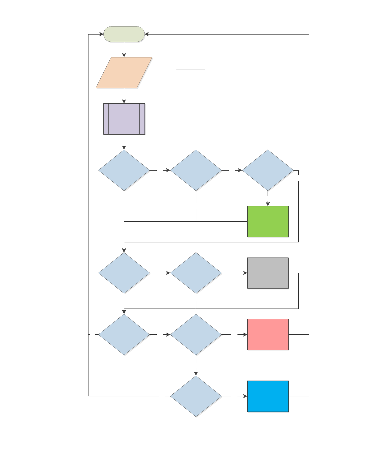
9.2 FAMU Sequence of Operation
Start
Read
Intake
Sensor
(TI & RHI)
TI ≥ (TSP + Diff1)?
DPI >=
(DPSP+Diff2)?
Calculate
Dew Points
(DPI & DPSP)
Turn On
Compressor
TE < (TSP – Diff3)?
TE > (TSP + Diff3)?
TI <= TSP? DPI <= DPSP?
Turn Off
Compressor
Increase
Electric Heat
Decrease
Electric Heat
Elec Heat
Update Interval
Expired?
Yes Yes
No
No
Yes Yes
No
Yes
No
No
Yes Yes
No
No
FAMU DX Operation Flowchart
Symbol Key:
TSP = Set Point Temperature
DPSP = Set Dew Point
TI = Intake Temperature
DPI = Intake Dew Point
RHI = Intake Relative Humidity
TE = Exhaust Temperature
Diff1 = Cooling Control Differential
Diff2 = Dew Point Control Differential
Diff3 = Heating Control Differential
A general overview of the FAMU DX Sequence of Operation is shown in Figure 11, and a general
overview of the FAMU CW Sequence of Operation is shown in Figure 12.
Micro-Air, Inc. Page 16 EasyTouch Operations Manual
Rev 3.0 4/3/17
Figure 11 - FAMU DX Sequence of Operation
Start
Read
Intake
Sensor
(TI & RHI)
TI ≥ (TSP + Diff1)?
DPI >=
(DPSP+Diff2)?
Calculate
Dew Points
(DPI & DPSP)
Turn On
Valve
TE < (TSP – Diff3)?
TE > (TSP + Diff3)?
TI <= TSP? DPI <= DPSP?
Turn Off
Valve
Increase
Electric Heat
Decrease
Electric Heat
Elec Heat
Update Interval
Expired?
Yes
No
No
Yes Yes
No
Yes
No
No
Yes Yes
No
No
Symbol Key:
TSP = Set Point Temperature
DPSP = Set Dew Point
TI = Intake Temperature
DPI = Intake Dew Point
RHI = Intake Relative Humidity
TE = Exhaust Temperature
TCW= Chilled-Water Loop Temperature
Diff1 = Cooling Control Differential
Diff2 = Dew Point Control Differential
Diff3 = Heating Control Differential
FAMU CW Operation Flowchart
TCW < TI?
Yes
Yes
No
Micro-Air, Inc. Page 17 EasyTouch Operations Manual
Rev 3.0 4/3/17
Figure 12 - FAMU CW Sequence of Operation

9.3 FAMU Settings & Recommendations
FAMU operation requires 3 important settings to insure proper operation of the system. Careful
consideration is recommended for each setting as described in detail below.
9.3.1 Exhaust Temperature Set Point (Factory default: 70°F/21°C)
This parameter sets the desired exhaust air temperature set point. The EasyTouch will apply
the necessary cooling and/or heating to attain this exhaust temperature within 2°F/1°C. It is
recommended that this setting be about equal to the lowest cabin control temperature set
point in all the spaces affected by this FAMU exhaust air.
9.3.2 Exhaust Relative Humidity Set Point (Factory default: 50%)
This parameter sets the desired exhaust air relative humidity. The EasyTouch will apply the
necessary cooling and/or heating to achieve a relative humidity that is at or below this setting.
Depending on the intake air temperature and relative humidity, it is recommended that this
setting be about equal to the desired relative humidity for all cabin spaces.
9.3.3 Fan Speed Setting (Factory default: Medium)
This parameter sets the fixed fan speed for all FAMU operation. Fan speeds are therefore
always manual during FAMU operation, and there is no automatic fan speed adjustment. It is
highly recommended that the fan speed be set to achieve the following:
a) High enough to provide the minimum number of air exchanges per hour as specified
for the spaces affected by this FAMU system.
b) Low enough to achieve the Exhaust Temperature and Relative Humidity Set Points.
IMPORTANT:
If the FAMU system is unable to achieve the Exhaust Temperature and Relative
Humidity Set Points, it is recommended that the Fan Speed Setting be reduced.
NOTE:
The selected Fan Speed, low, medium or high, can be more finely adjusted by
using setting the corresponding Fan Speed Programming Parameter. See
section 12.2 for more information on how to more precisely adjust the selected
fan speed.
10. FAULTS
There are a total of six different faults that the EasyTouch can declare. Only one applies during CW
operation and all six apply during DX operation.
When a fault is declared, it is displayed in the Status Area of the Home, Main, FAMU, and System Status
screens. Once the fault has cleared, the system will automatically delay 2 additional minutes (except for the
EasyStart Fault) and display “FLT DLY”, “FAULT DLY” or “FAULT DELAY”, before restarting a cooling or
heating cycle. At anytime during the fault condition or fault recovery delay, pressing and releasing over the
top of the fault status on the Main screen will display help information for the particular fault. See section
16.2 for more information on Fault Help.
Certain faults indicate a serious problem for the air conditioner. Any four faults of these types during a
single cooling or heating cycle will result in a LOCKOUT condition. Once a lockout occurs, the system will
not restart automatically. Operator intervention is required. To clear a lockout condition, power must be
cycled (turned off and back on again) via the Power button on the Home, Main, or FAMU display screens.
The fault count being monitored for lockout will be reset to zero upon the termination of the cooling or
heating cycle, or if power is cycled.
NOTE: The Air & FAMU Sensor Faults results in an immediate lockout condition. All other faults affect
lockout as described below.
Micro-Air, Inc. Page 18 EasyTouch Operations Manual
Rev 3.0 4/3/17

10.1 Air Sensor Fault (DX & CW, immediate lockout)
Main Screen Display: “FAULT SENSOR”
Status Screen Display: “FAULT INSIDE SENSOR”
Fault History Display: “SENSOR IN”
The EasyTouch can utilize one of 3 different temperature sensors for its Inside Temperature display
and use for control purposes:
Built-in Display Temperature Sensor
Alternate Air Temperature sensor plugged into the main FX1/FX2 control board
Cabin Combination Temperature/Humidity sensor plugged into the “INTAKE” jack on the FX2
Humidity Option Daughterboard (rev G1 and older, if equipped)
Cabin Combination Temperature/Humidity sensor plugged into the ALT. AIR / RH” jack on the
FX2 (rev J and newer) “.
Normally, the inside temperature sensor selection is determined automatically. (See section 12.1.16
for details on how to select the Inside Temperature sensor.) If a specific sensor is selected and it
malfunctions, or all of the potential inside temperature sensors have malfunctioned, the Air Sensor
Fault will be declared. Depending on which temperature sensor is required, replacing the failed
external temperature sensors or replacing the display itself may be necessary to remedy the problem.
10.2 FAMU Sensor Faults (FAMU only, immediate lockout)
FAMU Screen Display: “FAULT INTAKE SENSOR” or “FAULT EXHAUST SENSOR”
Status Screen Display: “FAULT INTAKE SENSR” or “FAULT EXHST SENSR”
Fault History Display: “SENSOR IN” or “SENSOR EX”
When FAMU is selected as the System Type (see section 9), both an intake and exhaust combination
temperature/humidity sensor need to be installed into the “OUTSIDE / RH” and “ALT. AIR / RH” jacks,
respectively, at all times. If either of these sensors fails to provide temperature and relative humidity
information, one of these faults will be declared. Check and replace the sensors as necessary, with
only approved types.
10.3 High Pressure Fault (DX & FAMU DX only, contributes to lockout count)
Main Screen Display: “FAULT HIGH PS”
FAMU Screen Display: “FAULT HIGH PRESSURE”
Status Screen Display: “FAULT HIGH PRES”
Fault History Display: “HIGH PRES”
The High Pressure Fault occurs whenever the system’s high pressure switch opens during
compressor operation or whenever it is open just before compressor start-up.
1. If the high pressure switch is open while the compressor is off, the most likely cause is an open
connection in the pressure switch itself.
2. If the high pressure switch opens while the compressor is operating in COOL mode, the most
likely cause is poor seawater flow or a fouled condenser.
3. If the high pressure switch opens while the compressor is operating in HEAT mode, the most
likely cause is poor air flow through the evaporator, possibly due to a clogged air filter.
10.4 Low Pressure Fault (DX & FAMU DX only, contributes to lockout count)
Main Screen Display: “FAULT LOW PS”
FAMU Screen Display: “FAULT LOW PRESSURE”
Status Screen Display: “FAULT LOW PRES”
Fault History Display: “LOW PRES”
The Low Pressure Fault occurs whenever the system’s low pressure switch opens during compressor
operation and remains open for at least 10 minutes, or whenever it is open just before compressor
start-up.
Micro-Air, Inc. Page 19 EasyTouch Operations Manual
Rev 3.0 4/3/17

1. If the low pressure switch is open while the compressor is off, the most likely cause is loss of
refrigerant charge in the system due to a leak.
2. If the low pressure switch is open while the compressor is operating in COOL mode, the most
likely causes are low refrigerant charge or cold seawater.
3. If the low pressure switch is open while the compressor is operating in HEAT mode, the most
likely causes are low refrigerant charge or cold inside air temperature. Setting the fan speed to
manual low can sometimes remedy low pressure faults in HEAT mode.
10.5 Low AC Fault (DX & FAMU DX only, no lockout)
Main Screen Display: “FAULT LOW AC”
FAMU Screen Display: “FAULT LOW AC”
Status Screen Display: “FAULT LOW AC”
Fault History Display: “LOW AC”
The Low AC Fault occurs whenever the AC line voltage is below the Low-Voltage Monitor parameter
setting during compressor operation for at least 5 minutes, or whenever it is below just before
compressor start-up. By default, the Low-Voltage monitor is not enabled. See section 12.3.3 for
more information on how to enable and set the voltage threshold for the Low-Voltage Monitor.
10.6 Pump Sentry Fault (DX & FAMU DX only, contributes to lockout count)
Main Screen Display: “FAULT PUMP”
FAMU Screen Display: “FAULT PUMP SENTRY”
Status Screen Display: “FAULT PUMP SENTRY”
Fault History Display: “PUMP SNTRY”
The Pump Sentry Fault occurs whenever the Service sensor temperature exceeds the Pump Sentry
parameter setting during compressor operation, or if it drops below 45°F/7°C (if Electric Heat is not
enabled; see section 12.1.14). Refer to section 6.3 for more information on how to install the optional
Service sensor, and section 12.3.5 for more information on how to enable and set the temperature
threshold for the Pump Sentry.
10.7 Overcurrent Fault (DX & FAMU DX only, contributes to lockout count)
Main Screen Display: “FAULT OVRCURR”
FAMU Screen Display: “FAULT OVERCURRENT”
Status Screen Display: “FAULT OVERCURRENT”
Fault History Display: “OVERCURR”
The Overcurrent Fault occurs whenever the system’s total AC current load exceeds the Current Limit
parameter setting for at least 30 seconds (sustained) or at any time prior to compressor startup while
the control is turned on. This fault protects the control board electronics, wiring, and compressor for
possible further damage.
The causes of overcurrent vary. Check the compressor and other AC loads for proper operation.
Also refer to the possible causes listed under the High Pressure Fault (section 10.3).
10.8 Lost AC Fault (DX & FAMU DX Only, no lockout)
Main Screen Display: “FAULT LOST AC”
FAMU Screen Display: “FAULT LOST AC”
Status Screen Display: “FAULT LOST AC”
Fault History Display: “LOST AC”
The Lost AC Fault occurs whenever the EasyTouch detects that the AC line voltage has been lost
during compressor operation (i.e. a brownout condition). Brownout conditions can cause
compressors to stall very quickly (<50ms), so this detection protects the compressor by shutting down
the compressor relay output and waiting for the normal fault recovery delay before attempting a
compressor restart.
Micro-Air, Inc. Page 20 EasyTouch Operations Manual
Rev 3.0 4/3/17

10.9 EasyStart Fault (DX & FAMU DX only, contributes to lockout count)
Main Screen Display: “FAULT EASYSTR”
FAMU Screen Display: “FAULT EASYSTART”
Status Screen Display: “FAULT EASYSTART”
Fault History Display: “EASYSTART”
The EasyStart Fault occurs whenever the EasyStart daughterboard system detects a problem with
the compressor during startup and during normal operation. This fault remains active for 5 minutes,
and so there is no additional 2-minute fault delay sequence after it is cleared as with all other faults.
The causes of EasyStart faults can be deciphered by examining the fault LEDs displayed on the
EasyStart daughterboard during the active fault. Refer to the chart below and also printed on the
daughterboard itself to determine the exact cause of the fault, and take appropriate action from there
to remedy the cause.
EasyStart LEDs Lit
EasyStart Fault D6 D3 D4
Overcurrent X
Overload (Klixon) Open X
Power Interruption X X
Compressor Stalled X X
Open Wire Connection X X X
11. MENU AND SETTINGS OVERVIEW
The Main Menu is accessed from the Main screen by pressing the MENU button. The Main Menu consists
of 6 items on 2 pages (screens) as shown in Figure 13. All menus are hierarchically designed. All submenus and the various parameter settings available are accessed starting from the Main Menu. All of the
parameter settings are stored in non-volatile memory and they are always retained, even when the battery
is removed. A unique set of parameter settings can be saved and recalled, or factory default settings can
also be recalled. Refer to sections 12.5, 12.8, and 12.9 for more information on memorizing and recalling
settings.
NOTE:
When the EasyTouch loses power, all of the parameter settings and the mode of operation
are retained indefinitely. When power is restored, the control resumes operation as last
programmed. The EasyTouch also has a battery to supply power to the real-time clock. If the
battery has completely discharged or has been removed, only the time and date settings will
be lost and will require resetting upon the next power up.
11.1 Menu Screen
All menu screens are constructed identically as shown in Figure 14. There are three large buttons to
choose from three sub-menu or parameter setting choices. Paging through the menu is possible by
using the DOWN ARROW button, and the current page number is always shown at the top. The
menu page will wrap around to page 1 again after the last page has been reached.
Micro-Air, Inc. Page 21 EasyTouch Operations Manual
Rev 3.0 4/3/17
Figure 13 – Main Menu Display Screens

1 2 3 4 5 1 2 3 4
Figure 14 – EasyTouch Menu Screen Layout
1. Home - Press this button at any time to return to the Home Screen.
2. Back - Press this button to return to the previous screen.
3. Scroll Down - Press this button go to the next page in the menu.
4. Menu Selection Options - Press any of these buttons to choose a new sub-menu or modify a
parameter setting.
11.2 Settings Screen
All of the parameter settings screens are constructed identically as shown in Figure 15. Some
parameters are numeric and some are text choices. In all cases, the UP/DOWN arrows allow
adjustment of the setting, and the SAVE button allows saving of the setting in non-volatile memory.
1. Home - Press this button at any time to discard any changes and return to the Home Screen.
2. Back - Press this button to discard any changes and return to the previous screen.
3. Up - Press the button to increase the setting to the next value or selection.
4. Down - Press the button to decrease the setting to the previous value or selection.
5. Save - Press this button save the desired setting change.
12. CONTROL PARAMETERS MENU
The Control Parameters Menu allows the adjustment of all the parameter settings that affect the physical
operation and configuration of the air conditioning system. Typically, the settings in this menu are accessed
only by qualified technical service person or a knowledgeable user. To access the Control Parameters
Menu, go to Main Menu and select Control Parameters.
Micro-Air, Inc. Page 22 EasyTouch Operations Manual
Rev 3.0 4/3/17
Figure 15 – EasyTouch Settings Screen Layout
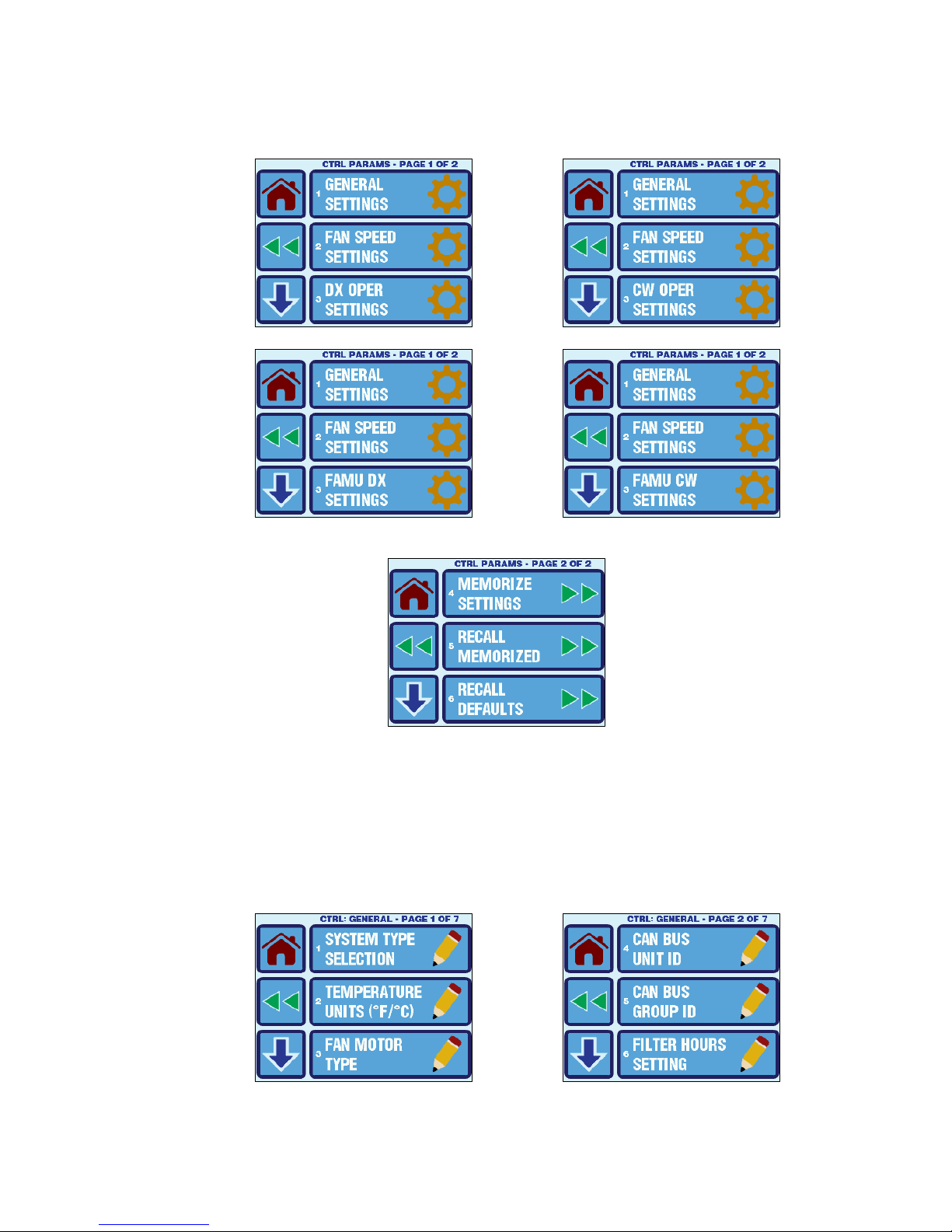
The Control Parameters Menu consists of 6 items on 2 pages as shown in Figure 17. Page 1 of the menu
will differ depending on whether the system is configured for DX, CW, FAMU DX, or FAMU CW operation.
Please see section 12.1.1 for more information on the System Type Selection.
Figure 16 – Control Parameters Menu Screen – Page 1 of 2 (shown for various System Types)
Figure 17 – Control Parameters Menu Screen – Page 2 of 2
12.1 General Settings
To access the General Settings, go to the Main Menu, select Control Parameters, and then select
General Settings. The parameters available in the General Settings Menu depend on the setting of
the first parameter in the listing, System Type Selection. See section 12.1.1 for more information on
this parameter. For standard DX/CW Operation, the General Settings Menu consists of 19 items on 7
pages as shown in Figure 18, and for FAMU Operation it consists of 11 items on 3 pages as shown in
Figure 19.
Micro-Air, Inc. Page 23 EasyTouch Operations Manual
Rev 3.0 4/3/17

Figure 18 – EasyTouch General Settings Menu Screens for Standard DX/CW System
Figure 19 – EasyTouch General Settings Menu Screens for FAMU System
Refer to Table 2 for a quick reference to the General Settings. Click the hyperlinks in the table to
refer to the sections that follow providing further details on each setting.
Micro-Air, Inc. Page 24 EasyTouch Operations Manual
Rev 3.0 4/3/17
 Loading...