

Page 1
LIMITED DISTANCE MODEM
USER MANUAL
by MICRO-AIDE CORP.
Page 2

.
Page 3

LIMITED DISTANCE MODEM
USER MANUAL
MICRO-AIDE CORP.
626-915-5502 [email protected]
Revised: June 16, 2009
A comprehensive document for the following LDM products:
• LDM-1 standlalone
• LDM-1 plug-in
• LDM-16 nest
Page 4

Copyright © 2007 by MICRO-AIDE Corporation
All rights reserved. No part of this document may be reproduced or transmitted in any form
or by any means without the written permission of MICRO-AIDE Corporation.
The information in this document is subject to change without notice. MICRO-AIDE believes
the information contained in this document to be accurate. However, MICRO-AIDE assumes
no responsibility for any errors or omissions.
Windows, Windows 98 and Windows XP are registered trademarks of Microsoft Corporation.
Page 5

iii
TABLE OF CONTENTS
CHAPTER 1GENERAL DESCRIPTION
Introduction. . . . . . . . . . . . . . . . . . . . . . . . . . . . . . . . . . . 1
Key Features . . . . . . . . . . . . . . . . . . . . . . . . . . . . . . . . . . 2
About This Manual . . . . . . . . . . . . . . . . . . . . . . . . . . . . . . . 2
Revision Level . . . . . . . . . . . . . . . . . . . . . . . . . . . . . . . 3
TxDOT Applications. . . . . . . . . . . . . . . . . . . . . . . . . . . . 3
C
HAPTER 2SETUP AND INSTALLATION
Introduction. . . . . . . . . . . . . . . . . . . . . . . . . . . . . . . . . . . 5
Unpacking . . . . . . . . . . . . . . . . . . . . . . . . . . . . . . . . . . . . 7
LDM-1 Basics . . . . . . . . . . . . . . . . . . . . . . . . . . . . . . . . . . 8
Network Types . . . . . . . . . . . . . . . . . . . . . . . . . . . . . . . . . 9
Point-to-Point . . . . . . . . . . . . . . . . . . . . . . . . . . . . . . . 9
Multi-drop Network . . . . . . . . . . . . . . . . . . . . . . . . . . . .10
Accessing the LDM-1 PCB . . . . . . . . . . . . . . . . . . . . . . . . . . .12
User Configured Settings . . . . . . . . . . . . . . . . . . . . . . . . . . . .12
Setup . . . . . . . . . . . . . . . . . . . . . . . . . . . . . . . . . . . . . .13
Rcv and Xmt Terminations (AX1 and AX2). . . . . . . . . . . . . . . .13
Enable Xmt Channel Busy Detector (AX3) . . . . . . . . . . . . . . . .14
RS-232 Protective Ground (AX5) . . . . . . . . . . . . . . . . . . . . .14
RTS to CTS Delay (SW2) . . . . . . . . . . . . . . . . . . . . . . . . .14
Equalization (SW3) . . . . . . . . . . . . . . . . . . . . . . . . . . . . .14
Permanently Asserting the RTS . . . . . . . . . . . . . . . . . . . . . .15
Installation . . . . . . . . . . . . . . . . . . . . . . . . . . . . . . . . . . .15
LDM-1 Standalone . . . . . . . . . . . . . . . . . . . . . . . . . . . . .15
LDM-1 Plug-in . . . . . . . . . . . . . . . . . . . . . . . . . . . . . . .16
LDM-16 Nest. . . . . . . . . . . . . . . . . . . . . . . . . . . . . . . .16
Attaching the Network Lines. . . . . . . . . . . . . . . . . . . . . . . .17
Connecting to the DTE . . . . . . . . . . . . . . . . . . . . . . . . . .17
C
HAPTER 3OPERATION
Introduction. . . . . . . . . . . . . . . . . . . . . . . . . . . . . . . . . . .19
Indicators and Controls . . . . . . . . . . . . . . . . . . . . . . . . . . . . .19
LEDs . . . . . . . . . . . . . . . . . . . . . . . . . . . . . . . . . . . .19
Page 6

LDM User Manual
iv
Select Mode Pushbutton Switch . . . . . . . . . . . . . . . . . . . . . . 20
Operating Modes . . . . . . . . . . . . . . . . . . . . . . . . . . . . . . . . 20
Normal Mode . . . . . . . . . . . . . . . . . . . . . . . . . . . . . . . 21
Test Mode A - Analog test with digital loop back . . . . . . . . . . . . . 22
Test Mode B - Analog loop back with DTE data . . . . . . . . . . . . . 22
Test Mode C - Analog loop back with test data . . . . . . . . . . . . . . 23
C
HAPTER 4MAINTENANCE
Introduction . . . . . . . . . . . . . . . . . . . . . . . . . . . . . . . . . . 25
PCB Removal and Insertion . . . . . . . . . . . . . . . . . . . . . . . . . . 25
Jumper and Switch Locations . . . . . . . . . . . . . . . . . . . . . . . . . 26
Trouble-Shooting Guide . . . . . . . . . . . . . . . . . . . . . . . . . . . . 27
A
PPENDIX ATECHNICAL DATA
LDM-1 Specifications . . . . . . . . . . . . . . . . . . . . . . . . . . . . . 29
LDM-16 Specifications . . . . . . . . . . . . . . . . . . . . . . . . . . . . . 30
Transmission Range Specifications. . . . . . . . . . . . . . . . . . . . . . . 30
Recommended Equalizations Settings . . . . . . . . . . . . . . . . . . . . . 31
DB-25 Connector Wiring . . . . . . . . . . . . . . . . . . . . . . . . . . . 31
A
PPENDIX BTXDOT APPLICATIONS
Introduction . . . . . . . . . . . . . . . . . . . . . . . . . . . . . . . . . . 33
Network Configurations . . . . . . . . . . . . . . . . . . . . . . . . . . . . 33
Point-to-Point . . . . . . . . . . . . . . . . . . . . . . . . . . . . . . . 33
Multi-Drop . . . . . . . . . . . . . . . . . . . . . . . . . . . . . . . . . 34
RS-232 Cables . . . . . . . . . . . . . . . . . . . . . . . . . . . . . . . . . 34
LCU to LDM-1 . . . . . . . . . . . . . . . . . . . . . . . . . . . . . . 34
PSDM to LDM-1 . . . . . . . . . . . . . . . . . . . . . . . . . . . . . 34
ADU to LDM-1 . . . . . . . . . . . . . . . . . . . . . . . . . . . . . . 34
Test Software . . . . . . . . . . . . . . . . . . . . . . . . . . . . . . . . . . 35
Requirements. . . . . . . . . . . . . . . . . . . . . . . . . . . . . . . . 35
Installation . . . . . . . . . . . . . . . . . . . . . . . . . . . . . . . . . 35
Test Procedure . . . . . . . . . . . . . . . . . . . . . . . . . . . . . . . 36
Page 7

1
CHAPTER 1
GENERAL DESCRIPTION
INTRODUCTION
MICRO-AIDE’s family of Limited Distance Modem (LDM) products can be
used in a variety of data communications applications. The family consists of
the following products.
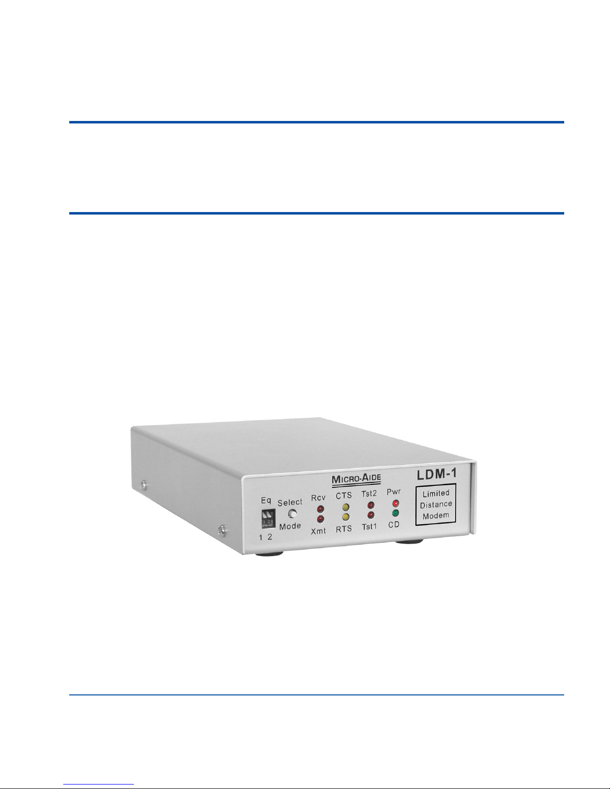
• LDM-1 standalone - a complete LDM (photographed on the cover page of
this manual).
• LDM-1 plug-in - functionally identical to the standalone version, it is a
printed circuit board (PCB) that is mounted within the LDM-16 nest.
• LDM-16 nest - a 19" rack-mounted chassis that can be equipped with 1 to
16 LDM-1 plug-in PCBs.
The LDM-1 can be thought of as a device for extending RS-232 communications over great distances (e.g., thousands of feet). It serves as an interface
between the customer’s Data Terminal Equipment (DTE) and data communications network. It is designed to be compatible with four-wire, private line
networks. It can be used to facilitate point-to-point and multi-drop network
configurations. Its unique performance characteristics permit data transmission and reception over distances of many miles. Additionally, the LDM-1 will
operate over a wide temperature range.
Page 8

LDM User Manual
2
The LDM-1 is easy to install and operate. Several self-test modes allow the
user to verify its performance and network segment integrity. Light Emitting
Diode (LED) indicators inform the user of all critical functions.
KEY FEATURES
Listed below are just a few of the features associated with MICRO-AIDE’s
family of LDM products.
• Broad transmission range, up to 25 miles, point-to-point, at 4800Baud.
• Data transparent transmission and asynchronous operation.
• Baud rates from 75 to 19,200.
• Supports multi-drop configurations of up to eight LDM-1s. Transmission
distance and data rate performance are not de-rated by adding drop points.
• Standard DB-25 female connector provides simple cabling to any RS-232
device.
• Easy-to-activate analog and digital loop back test modes.
• Includes transmit channel detector to avoid data transmission collisions.
Data contention can be resolved at the LDM-1, not at the DTE.
• Allows full duplex operation on four wires.
• Compact size, LDM-1 standalone footprint is approximately 5" by 8" and
less than 2lbs. in weight.
• LDM-16 nest can be equipped with 1 to 16 LDM-1 plug-in PCBs for applications requiring multiple network interfaces at a single location.
ABOUT THIS MANUAL
This document is intended to provide the user with comprehensive, easy-toread instructions on how to install, set up, operate and maintain all three
LDM products. Wherever possible, step-by-step instructions are listed. In the
event the user has questions about any of the described procedures the user
should contact MICRO-AIDE for assistance.
Page 9

General Description - About This Manual
3
MICRO-AIDE Corp.
685 Arrow Grand Circle, Covina, CA 91722
Tel: 626-915-5502 Fax: 626-331-9484
E-mail: [email protected]
The MICRO-AIDE Material Return and Limited Warranty policies can be
found on the inside back cover of this manual.
R
EVISION LEVEL
This User Manual makes specific reference to Revision D of the LDM-1.
Additionally, this manual is applicable to LDM-1s that have been factory
reworked to the Revision D level. The revision level can be found near the
lower right-hand corner of the LDM-1’s printed circuit board (PCB).
T
XDOT APPLICATIONS
The LDM products are frequently used with MICRO-AIDE’s Local Control
Unit (LCU) and other data communications devices throughout the State of
Texas. They have been approved by the Texas Department of Transportation
for use in various highway communications networks. Appendix B includes
information specific to these applications.
Page 10

LDM User Manual
4
USER NOTES
Page 11

5
CHAPTER 2
SETUP AND INSTALLATION
INTRODUCTION
This chapter describes how to properly unpack, set up and install each of the
MICRO-AIDE LDM products. Typical point-to-point and multi-drop network installations are described.
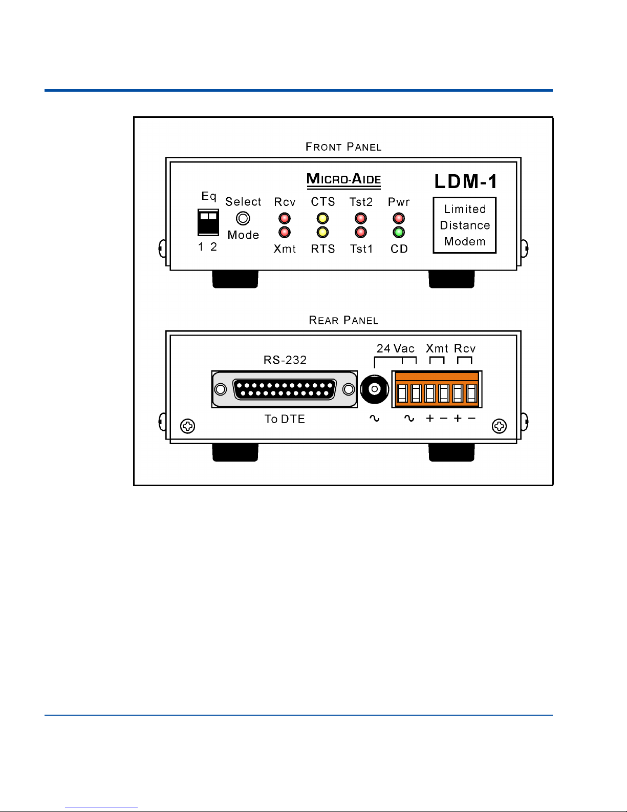
Figure 1 on page 6 includes an illustration of the front and rear panels of the
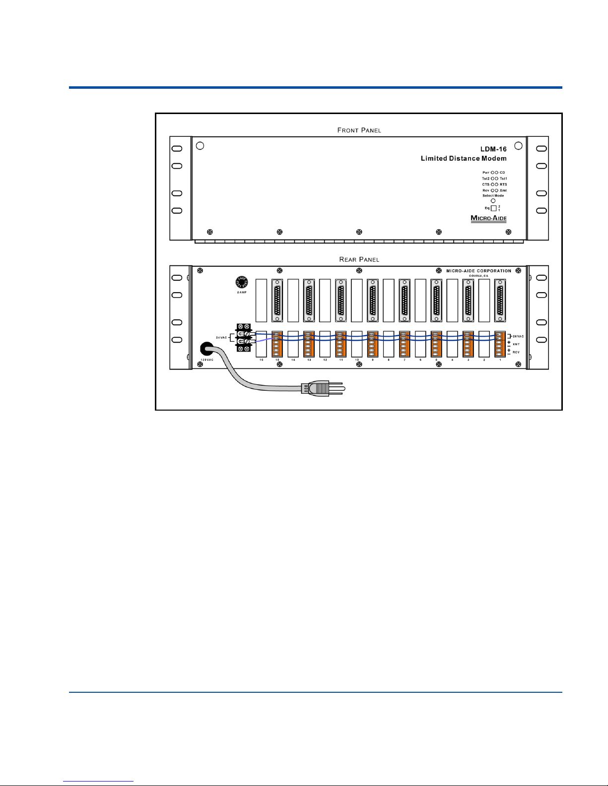
LDM-1 standalone modem. The LDM-16 nest is illustrated in Figure 2 on
page 7.
NOTE: Unless otherwise stated, the term LDM-1 will refer to either version
of the modem (i.e., LDM-1 standalone and LDM-1 plug-in).
TIP: The LDM-1 must be properly configured before it can be put into
operation. As the setup procedure requires that the user have access to the
LDM-1 PCB, it is advisable that the user complete the setup procedure
described herein and then proceed to install the modem.
Page 12
LDM User Manual
6
Figure 1 - LDM-1 Standalone
Page 13
Setup and Installation - Unpacking
7
UNPACKING
The LDM-1 standalone and LDM-16 nest are packed in individual containers
that are properly sized for the unit. The LDM-1 plug-in PCBs are secured
inside the LDM-16 nest. Abundant packing materials are provided to minimize mechanical shock to the contents. Before opening the shipping carton
inspect the carton for damage. Damage to the container should be noted.
Carefully remove the unit. It is advisable to save all packing materials in the
event the unit ever needs to be returned to MICRO-AIDE.
Inspect each unit and PCB for any visual damage. The unit should not be
scratched, dented or deformed in any way. If it appears that the unit was damaged in shipment the responsible carrier should be notified immediately.
MICRO-AIDE will assist the user in filing a claim in the event damage was
sustained during shipment.
Figure 2 - LDM-16 Nest
Page 14

LDM User Manual
8
LDM-1 BASICS
The LDM-1 can be thought of as a device that extends the distance that
RS-232 serial data can be transmitted and received. It does so over four-wire
(i.e., two pair) private line networks. It includes a standard DB-25 female connector that allows for direct connection to any DTE device. The LDM-1 is
configured as a DCE device. Refer to Figure 7 on page 31.
Regardless of the network configuration (refer to section entitled “Network
Types” on page 9) at least two modems must be used. The master modem
broadcasts to one or more slave modems. Each slave modem listens to the
data on its receive channel and passes that data to its DTE device. Under control of its DTE device only one of the slave modems is allowed to respond at
a time to the master modem’s message. The slave modem sends data via its
transmit channel.
The basic transmit and receive methodology employed is summarized by the
following rules.
• Only one master modem can be employed per network.
• The master modem broadcasts simultaneously to every slave modem.
• Only one slave modem can respond to the master modem at a time. It can
only transmit data to the master modem (i.e., not to another slave modem).
• The slave DTE device, via its application, controls the response of each
slave modem.
• Hardware flow control must be enabled within each DTE device. Specifically, the DTE device must not attempt to send data until its modem has
asserted its Clear to Send (CTS) signal.
• If only two modems are used, as is the case in a point-to-point network, the
RTS signal of each modem can be permanently asserted. Refer to the section
entitled “Permanently Asserting the RTS” on page 15.
NOTE: The LDM-1 (master or slave) will only transmit data when its
Request to Send (RTS) signal is asserted and the LDM-1 has in response
asserted its CTS signal.
Page 15

Setup and Installation - Network Types
9
NETWORK TYPES
The LDM-1 has several options and performance settings that can be configured by the user. Equalization, line termination and timer settings are among
the various items. Before the LDM-1 can be properly set up the type of network that will be used must be understood and selected. The LDM-1 is
designed for use in point-to-point and multi-drop networks. They are
described in the following two sections.
P
OINT-TO-POINT
The point-to-point network is the simplest of the two configurations. It is
characterized by a two-pair cable and a single modem at each cable end. The
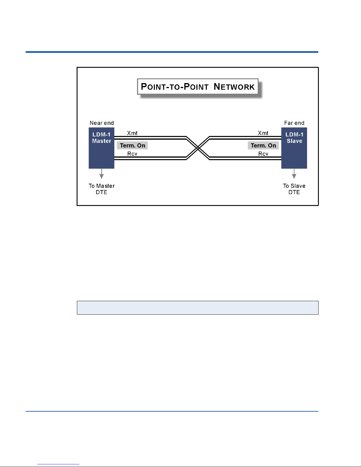
cable pairs are referred to as Xmt and Rcv for transmit and receive, respectively. Figure 3 on page 10 illustrates a typical point-to-point network.
The proper LDM-1 setup configuration for a point-to-point network is as follows:
• The Xmt and Rcv Terminations for both modems must be set to On.
• Since only two modems are used, the RTS signal of each modem can be permanently asserted. Refer to the section entitled “Permanently Asserting the
RTS” on page 15.
• The end-to-end cable length must not exceed the recommendations as listed
in Table 5 on page 30 for the given cable diameter and selected Baud rate.
• The Equalization setting for both modems must be identical and set in
accordance with the recommendations as listed in Table 6 on page 31.
WARNING: The LDM-1 cannot be used in a star network configuration
involving spoke lengths that are greater than 100ft.
Page 16
LDM User Manual
10
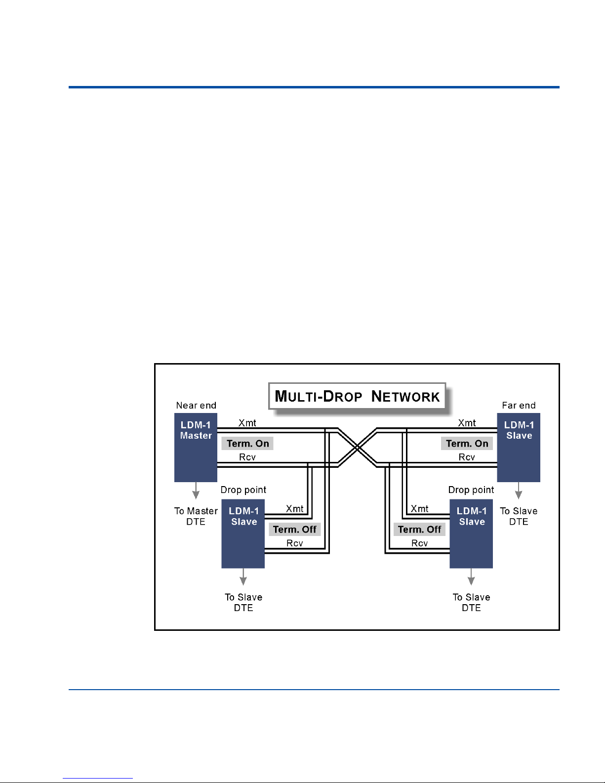
MULTI-DROP NETWORK
The multi-drop network involves two or more, two-pair cable segments. Each
cable segment includes a Xmt and Rcv cable pair. The ends of the cable are
connected to a single modem. These modems are also referred to as the nearand far-end modems. The master modem is located at the near end. The far
end is equipped with a slave modem. The intersection of two cable segments
forms a drop point. A slave modem can be connected to the network at each
drop point. Figure 4 on page 11 illustrates a typical multi-drop network.
The proper setup configuration for a multi-drop network is as follows:
• The Xmt and Rcv Terminations for the near- and far-end modems must be
set to On.
• The Xmt and Rcv Terminations for each modem at a drop point must be set
to Off.
Figure 3 - Typical Point-to-Point Network
NOTE: A multi-drop network is limited to no more than eight modems.
Page 17
Setup and Installation - Network Types
11
• The RTS signal of the master modem can be permanently asserted. Refer to
the section entitled “Permanently Asserting the RTS” on page 15.
• RTS-CTS flow control must be used by each DTE device connected to a
slave modem.
• The near- to far-end cable length must not exceed the recommendations as
listed in Table 5 on page 30 for the given cable size and selected Baud rate.
• The Equalization setting for the near- and far-end modems must be identical
and set in accordance with the recommendations as listed in Table 6 on
page 31. Assume a cable length equal to the near-end to far-end cable length.
• The Equalization setting for a drop point modem must also be set in accordance with the recommendations as listed in Table 6 on page 31. Assume a
cable length equal to the length between the near-end modem (i.e., master)
and the drop point modem.
Figure 4 - Typical Multi-Drop Network
Page 18
LDM User Manual
12
ACCESSING THE LDM-1 PCB
The various LDM-1 settings are controlled by jumpers and switches. They are
located on the LDM-1’s PCB. Only the Equalization (SW3) setting can be
accessed externally of the standalone modem. The other settings require that
the cover of the standalone unit be removed or that the plug-in PCB be
removed from its LDM-16 nest.
The cover of the standalone unit can be removed by removing the four screws
at the side of the unit. The plug-in PCBs can be removed by first unfastening
the hinged front cover of the LDM-16. Remove the PCB retaining bar located
at the top front edge of the nest. It is secured by two screws. The xmt/rcv and
power connectors should then be unfastened at the rear of the nest. Remove
the plug-in PCB by depressing the PCB retainer at the bottom front edge of
the nest while rotating the PCB’s card ejector upward.
USER CONFIGURED SETTINGS
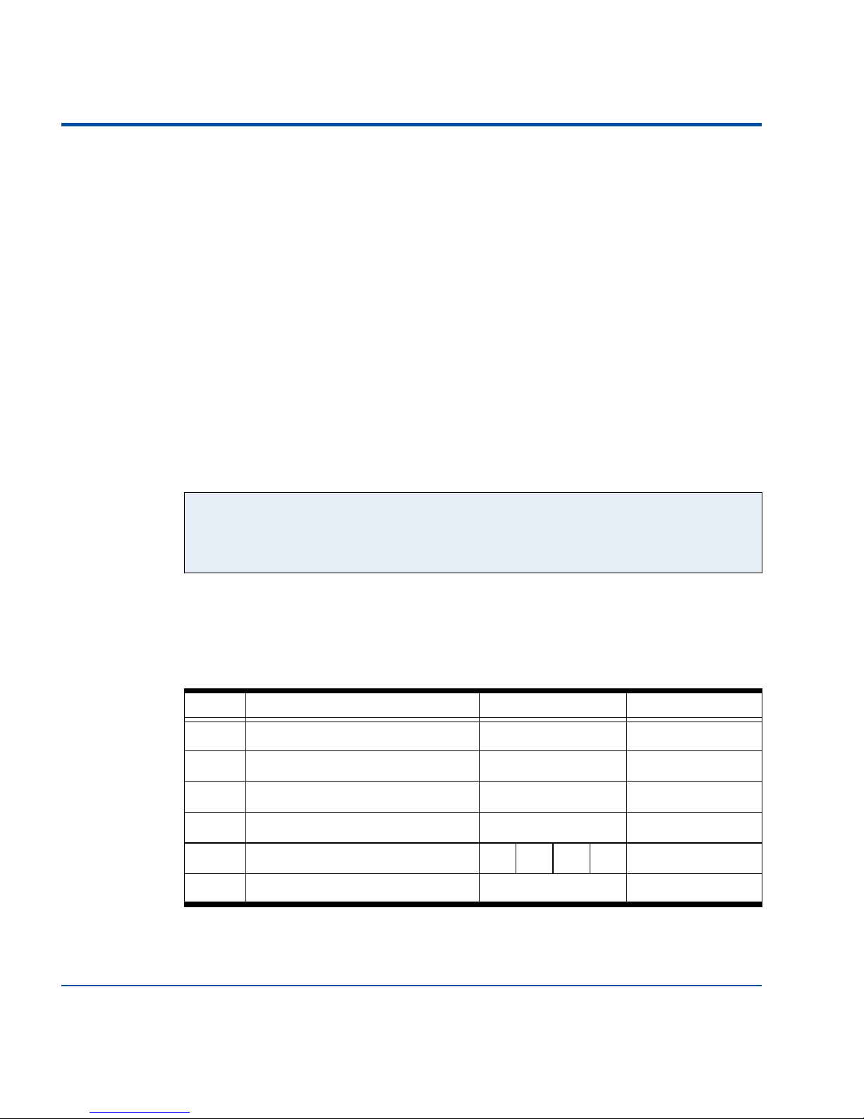
Two switch assemblies and four jumpers comprise the collection of user configured settings. Table 1 provides a brief definition of each setting. Also
included in Table 1 are the factory default settings.
CAUTION: Electrostatic discharges can cause serious damage to electronic
components. Normal anti-static precautions are recommended when handling the LDM-1 PCB.
Label Description Position / Setting Default Setting
AX1 Receive channel termination On or Off On (150Ohms)
AX2 Transmit channel termination On or Off On (150 Ohms)
AX3 Transmit channel busy detector On or Off Off (disabled
AX5 RS-232 protective ground On or Off Off (isolated)
SW2 RTS to CTS delay (msec.) 64 32 16 8 8 msec.
SW3 Receive channel Equilization see below Minimum
Table 1 - User Configured Settings
Page 19
Setup and Installation - Setup
13
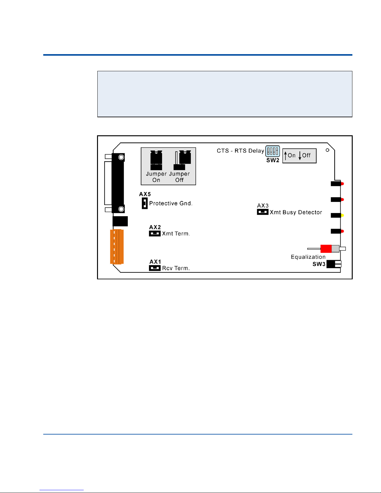
Figure 5 illustrates the location of each setting on the LDM-1 PCB.
SETUP
In the sections that follow a description is provided for each jumper and
switch setting. A description of how to permanently assert the modem’s RTS
signal is also provided.
R
CV AND XMT TERMINATIONS (AX1 AND AX2)
AX1 and AX2 allow the user to select either a 150Ohm (On) or high impedance (Off) termination. These jumpers are used in accordance with the following rules.
• The AX1 (Rcv) and AX2 (Xmt) settings must always match each other.
• Irrespective of the type of network, always terminate the extreme ends of
the network (i.e., the near and far ends).
NOTE: The factory default switch and jumper settings for AX1 through AX5
and SW2 are satisfactory for use with a point-to-point network. The Equalization setting controlled by SW3 may need to be changed as required by the
length of cable being used.
Figure 5 - LDM-1 PCB
Page 20

LDM User Manual
14
• If two modems are located at an end point in the network only one modem
should be terminated.
• Never terminate a modem located at a drop point.
• There should never be more than two terminations per network channel.
E
NABLE XMT CHANNEL BUSY DETECTOR (AX3)
The LDM-1 has a built-in carrier detector for its transmit channel. When
enabled, the LDM-1 will not assert its CTS signal until it verifies that a carrier
is no longer present at the transmit channel. This feature prevents two
modems from attempting to transmit simultaneously. To enable the busy
detector, set the AX3 jumper. The factory default setting is Off.
RS-232 P
ROTECTIVE GROUND (AX5)
Installing the jumper at AX5 will connect the signal ground of the LDM-1 to
the protective ground of the DTE device. Generally, the LDM-1 and DTE
can be left isolated from one another by leaving the jumper set to Off. The
LDM-1 is provided 24Vac power by a fully isolated transformer. The factory
default setting is Off.
RTS
TO CTS DELAY (SW2)
The LDM-1 will respond to the DTE’s RTS signal by asserting its CTS signal.
The delay from RTS to CTS is controlled by the SW2 setting. The delay can
be used to ensure that the transmit channel is available. SW2 allows the user to
select any of four settings. Only one switch must be closed. Refer to Table 1
on page 12. Silkscreening on the LDM-1 PCB lists the correspondence
between switch position and delay. The factory default setting is 8msec.
E
QUALIZATION (SW3)
SW3 is a dual position switch that is accessed from the front panel of the
modem. Refer to Figure 1 on page 6. SW3 allows the user to set the Equalization level required to compensate for the transmission characteristics of the
cable being used. To provide the broadest performance range possible, four
CAUTION: Failure to provide the correct termination and Equalization set-
tings can result in significant communication errors.
Page 21

Setup and Installation - Installation
15
distinct settings are available. Table 2 details the correspondence between
Equalization settings and switch positions.
Selecting the proper Equalization setting relates directly to cable length and
wire diameter. The higher settings are used when the master and slave
modems are separated by a greater distance and/or a smaller wire diameter is
employed. Table 6 on page 31 includes a list of suggested Equalization settings. The factory default Equalization setting is 1 (i.e., minimum).
P
ERMANENTLY ASSERTING THE RTS
The LDM-1 can be used with DTE interfaces that lack RTS and CTS signals
provided the modem’s use is limited to point-to-point networks or as a master
in a multi-drop network. For these applications the DTE-to-modem cable
must include a jumper between pins 4 (RTS) and 6 (DSR) at the LDM-1 end.
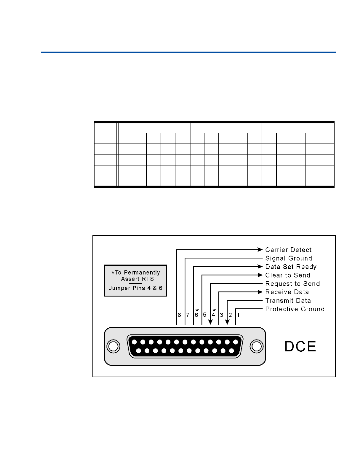
This technique will force the modem’s RTS to be constantly asserted. Figure 7
on page 31 illustrates the pin assignments used by the LDM-1’s DB-25 connector.
INSTALLATION
Physical installation of the modems and nests can be performed after the configuration settings are in place.
LDM-1 S
TANDALONE
The standalone version LDM-1 can be placed in any convenient location. It
generates very little heat and utilizes no hazardous voltages. A desktop or
shelf within several feet of the network lines is perfectly satisfactory as a
Equalization
Setting
Switch 3-1 Switch 3-2 Cable
Length
1 (min. default) On On Short
2 Off On Mid-range
3 On Off Mid-range
4 (max.) Off Off Long
On=down Off=up
Table 2 - Equalization Settings
Page 22

LDM User Manual
16
mounting location. The standalone modem comes equipped with four vibration absorbing rubber feet. It is powered by a 24Vac wall mount transformer
(included with the LDM-1 standalone). Nearby access to 120Vac power is
required. The female connector of the transformer plugs directly into the
round, male connector located at the rear panel of the modem. Refer to
Figure 1 on page 6. The modem is always on when power is connected.
LDM-1 P
LUG-IN
The user may find it necessary to install the correct complement of PCBs into
the LDM-16 before the nest can be used. LDM-1 plug-in PCBs are installed
by unfastening the front cover of the nest, depressing the PCB retainer bar
and inserting the PCB into the plastic card guides. The PCB should be pushed
as far forward as possible. The retainer bar should then spring back, locking
the PCB in place. If fewer than nine modems are being installed it is recommended that an empty slot be left between adjacent PCBs. It may be necessary
to remove the plastic shield that covers the rear connector cut-outs before the
PCB can be inserted. Spare plastic shields should be used to cover any vacant
cut-outs.
The nest is equipped with a 120-to-24Vac transformer. The 24Vac power
source must be connected to each PCB. Use the connector harness provided
for this purpose. It can be used to daisy-chain as many as eight PCBs together.
Additional connectors can be easily attached to the end of the standard harness.
LDM-16 N
EST
The LDM-16 nest is a chassis that can be installed in any standard 19" equipment rack. It includes a pair of rack mounting brackets. It is 5.75" high and
requires four rack increments of vertical space. The chassis can be secured at
NOTE: The ambient operating temperature of the all LDM products is -4ºF
(-20ºC) to 158ºF (70ºC).
WARNING: The two-position power connector must be inserted on the top
two pins of the PCB's six-position connector. Failure to do so will result in
damage to the PCB.
Page 23

Setup and Installation - Installation
17
any convenient location in the rack with four screws. Figure 2 on page 7 provides front and rear views of the LDM-16. The nest requires access to 120Vac
power. It is equipped with a 2Amp fuse located along the rear panel.
A
TTACHING THE NETWORK LINES
The LDM-1 is designed to operate with four-wire private line networks. Both
the transmit and receive channels are polarity sensitive. The network’s + conductor must always be wired to a corresponding + input at the rear panel.
Network lines are secured to appropriate screw-down terminals at the quickdisconnect plug. The rear panel silk screening clearly labels each connector
position. The cable that connects the LDM-1 to the network should be limited to 100ft. in length.
C
ONNECTING TO THE DTE
The LDM-1 can be used with any DTE that utilizes an RS-232 interface. The
LDM-1’s operation is asynchronous. It uses the Baud rate selected by the
DTE. The DTE connects to the DB-25 female connector located at the
modem's rear panel. The pin assignments for the modem’s DB-25 connector
are listed in Figure 7 on page 31. It is wired in accordance with DCE standards.
This completes the chapter on how to set up and install the various LDM
products. The next chapter describes how to operate the modem and how to
use its self-test features.
Page 24

LDM User Manual
18
USER NOTES
Page 25

19
CHAPTER 3
OPERATION
INTRODUCTION
This chapter describes how to operate the LDM-1. An explanation of each
LED indicator and use of the Select Mode pushbutton switch are also provided. Normal operation and the three test modes are described.
INDICATORS AND CONTROLS
LEDS
The front panel of each LDM-1 includes a set of eight, multi-colored LED
indicators. The location of each LED and the Select Mode pushbutton switch
is depicted in Figure 1 on page 6. The operational mode and signal status of
the modem is conveyed via the LEDs. A description of each LED is listed in
Table 3 on page 20.
Page 26

LDM User Manual
20
SELECT MODE PUSHBUTTON SWITCH
The Select Mode pushbutton switch located at the front panel is used to select
the operating mode of the LDM-1. The Normal Mode of operation occurs
automatically when the unit is first powered up. By momentarily pressing the
Select Mode pushbutton switch, the modem can be advanced from Normal
Mode to Test Mode A, Test Mode B, Test Mode C and finally back to Normal Mode. Each time the pushbutton switch is pressed the modem advances
one step in the cycle.
OPERATING MODES
Each of the four operating modes are described in the following sections.
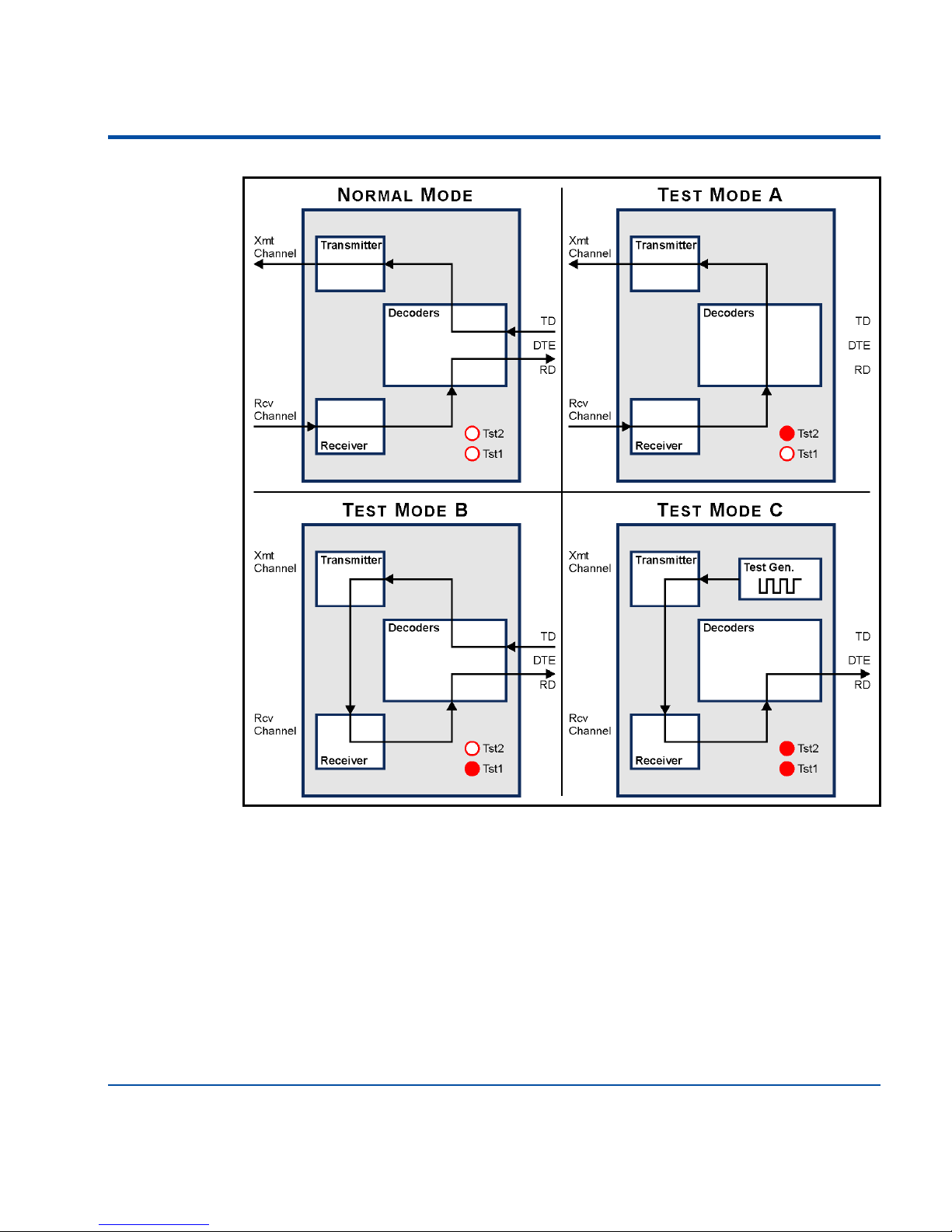
Figure 6 on page 21 illustrates the signal flow applicable to each operating
mode.
Label Name Color
Description
Pwr Power Red Modem has internal 5Vdc power
CD Carrier Detect Green Data is present on receive channel
Flashes if Test Mode C is receiving data
Tst2 & Tst1 Test 2 & Test 1 Red Off & Off: Normal Mode
On & Off: Test Mode A
Off & On: Test Mode B
On & On: Test Mode C
CTS Clear to Send Amber DTE can send data
RTS Request to Send Amber DTE has asserted RTS
Rcv Receive Data Red Receive channel is receiving data
Xmt Transmit Data Red Transmit channel is transmitting data
Table 3 - LED Indicators
NOTE: Regardless of the operating mode selected the transmit and receive
channels will remain terminated in accordance with the user's selections.
Page 27
Operation - Operating Modes
21
NORMAL MODE
Normal Mode is automatically selected when the LDM-1 is powered up. The
modem will transmit/receive data to/from the network in accordance with
the jumper and switch settings selected in the setup procedure. The RS-232
interface will be fully operational. The Tst2 and Tst1 LEDs are off when the
modem is in Normal Mode.
Figure 6 - Test Mode Signal Flow
Page 28

LDM User Manual
22
TEST MODE A - ANALOG TEST WITH DIGITAL LOOP BACK
In Test Mode A the analog signal present at the receive channel is decoded
into a digital data signal. The receive data signal is then presented to the
modem’s transmitter section. The transmitter outputs the decoded data via
the transmit channel. In Test Mode A the Tst2 and Tst1 LEDs will be on and
off, respectively. The DTE interface is disabled in this test mode. The CD
indicator will operate normally. The RTS and CTS indicators will illuminate in
accordance with the DTE status. Neither signal, however, has an effect on
Test Mode A. The Rcv and Xmt indicators will be off.
Test Mode A can be used to perform an effective end-to-end test of a network segment. The modem at the end of the segment under test should be
placed in Test Mode A. All other modems should be left in Normal Mode.
Transmitted data will be returned to the source modem’s receiver where it can
be checked against the originally transmitted data.
T
EST MODE B - ANALOG LOOP BACK WITH DTE DATA
Test Mode B loops the analog output signal of the transmit channel to the
input of the receive channel. The data to be transmitted is provided by the
DTE. The transmit and receive channels are left terminated but are disconnected from the test data (i.e., test data is not sent to the network). In Test
Mode B the Tst2 and Tst1 LEDs will be off and on, respectively. The CD
indicator will be off. The RTS and CTS indicators will be either on or off
depending upon the status of the DTE. The Rcv and Xmt indicators will illuminate when data is being received and transmitted, respectively. The RTS signal does not need to be asserted in this test mode.
Test Mode B is useful in checking major elements of the modem and DTE
interface.
TIP: Test Mode A requires the same equalization setting as Normal Mode.
TIP: Test Mode B requires an equalization setting of 1 (i.e., minimum).
Page 29

Operation - Operating Modes
23
TEST MODE C - ANALOG LOOP BACK WITH TEST DATA
Test Mode C also loops the transmit channel’s analog output signal to the
input of the receive channel. However, the transmitted data is provided by an
on-board test data generator. The test data consists of alternating mark and
space bits. The test data has a Baud rate of 19,200. The receive and transmit
channels are left terminated but are disconnected from the test data (i.e., test
data is not sent to the network). In Test Mode C the Tst2 and Tst1 LEDs are
both on. The CD LED will flash as an indication that the test data is being
received properly. The RTS, CTS and Xmt indicators will illuminate depending upon the status of the DTE interface. However, these signals are ignored
in Test Mode C. The Rcv indicator will be on.
Test Mode C can also be used to test the modem separately from the network
and DTE. If a DTE is connected it should display a sequence of U characters
(i.e., ASCII code 85).
This completes the chapter on how to operate the LDM-1. The next chapter
describes maintenance of the modem.
TIP: Test Mode C requires an equalization setting of 1 (i.e., minimum).
Page 30

LDM User Manual
24
USER NOTES
Page 31

25
CHAPTER 4
MAINTENANCE
INTRODUCTION
The primary purpose of this chapter is to describe the recommended troubleshooting method to be used with the LDM products. It should be referred to
if ever a questionable symptom arises during the operation of any LDM
device.
The LDM products are designed to provide users with many years of troublefree operation. There are no user serviceable components in any LDM device.
There are no consumable items or supplies that need to be replaced or replenished. The user may, occasionally, need to wipe dust away from the external
surfaces of a unit. This should be done with a clean, dry cloth. The mechanical design of the housing and chassis provide the electronic assemblies with a
nearly sealed environment. Due to the low power requirement of each product, ventilation holes are not required. The inside of each unit should remain
clean indefinitely.
PCB REMOVAL AND INSERTION
The PCB inside the standalone version LDM-1 should never be removed
from its aluminum case. Internal jumpers and switches are accessible once the
top cover is removed. However, access to the user configured settings of the
LDM-1 plug-in PCB installed within the LDM-16 nest require removal of the
Page 32

LDM User Manual
26
PCB. PCB removal should be performed in accordance with the following
procedure. Refer to Figure 2 on page 7. Power to the nest can be left on while
PCBs are being removed and inserted. Damage will not occur provided normal care is exercised.
• Disconnect the cables attached to the PCB at the rear of the nest. Modems
are labeled 1 through 16.
• Open the hinged front cover.
• If the PCB bracket is still in place remove it from the chassis by unscrewing
both ends. The PCB bracket can be discarded. While depressing the PCB
retainer bar, rotate the PCB ejector upward and remove the PCB from the
chassis.
• Inspect or replace the PCB. Change the setup configuration as necessary.
• Install the PCB by aligning its edges with the plastic card guides secured to
the top and bottom panels of the nest. Push the PCB forward until it clears
the retainer bar.
• Attach any cables to their respective PCB connectors. Cables are keyed, so
they can be inserted in only one direction. Do not force a cable into a connector.
• Close the front cover.
JUMPER AND SWITCH LOCATIONS
Several jumpers and switches are mounted on the LDM-1 PCB. Only SW3,
which controls the receive channel Equalization setting, is accessible exter-
CAUTION: Electrostatic discharges can cause serious damage to electronic
components. Normal anti-static precautions are recommended when handling the LDM-1 PCB.
WARNING: The two-position power connector must be inserted on the top
two pins of the PCB's six-position connector. Failure to do so will result in
damage to the PCB.
Page 33

Maintenance - Trouble-Shooting Guide
27
nally. The identity and location of each jumper and switch is illustrated in
Figure 5 on page 13.
TROUBLE-SHOOTING GUIDE
The following guide will assist the user in resolving problems that may occur
with the operation of the LDM-1. It can be especially helpful when attempting to operate the modem for the first time. Procedures for resolving both
local and remote problems are listed. Where multiple steps are indicated it is
recommended that they be performed in the order listed. Removal of any
PCB should be performed in accordance with the procedures described earlier
in this chapter.
The three test modes can be very helpful in isolating problems. Refer to the
previous Chapter 2 entitled Operation for instructions on how to use the test
modes. If the user is still unable to resolve the problem, MICRO-AIDE customer service should be contacted. The user will be asked to state the problem, specify related symptoms, and indicate any operations or conditions that
have a bearing on the problem.
Symptom or Problem Resolution
No indication of power Measure 22-26Vac across power pins of
quick-disconnect connector
DTE data is never transmitted Verify RTS is asserted by DTE
Verify DTE-LDM cable wiring
RTS is asserted, but CTS is not asserted Verify one switch in SW2 is closed
Verify Tst2 and Tst1 are off (Normal
Mode)
Transmit channel may be occupied by
another slave modem
Transmit data is being sent, but Rcv
LED never illuminates
Check polarity of transmit and receive
channels’ ± connections
Table 4 - Trouble Shooting Guide
Page 34

LDM User Manual
28
This completes the User Manual for the LDM-1. Two appendices have been
provided. They include detailed specifications for each of the LDM products
and additional information concerning Texas DOT related applications.
Any comments the reader may have on how to improve this manual are welcomed. Comments can be forwarded to the Director of Marketing,
MICRO-AIDE Corporation.
Receive data contains errors Change Equalization settings to better
match cable transmission properties
Termination settings are incorrect
(should measure 150Ohm if On,
40KOhm if Off)
Test Mode B does not echo sent character
Set Equalization to setting 1 (minimum)
U character is not issued in Test Mode C Set Equalization to setting 1 (minimum)
Change Baud rate at DTE to 19,200
Table 4 - Trouble Shooting Guide (Continued)
Page 35

29
APPENDIX A
TECHNICAL DATA
LDM-1 SPECIFICATIONS
Physical
Length: 8.6"
Width: 5.3"
Height: 1.9"
Weight: 22oz.
Environmental
Storage
Tem perat ur e: -20ºF to 180ºF
Humidity: 0% to 95% non-con-
densing
Operating
Tem perat ur e: -4ºF to 158ºF
Humidity: 0% to 95% non-con-
densing
Mounting
Shelf or desktop
Construction
Housing
Fully enclosed, anodized aluminum
Removable cover allows
access to inside
Externally accessible LEDs and
connectors
Electrical
Single, conformal coated, PCB
inside housing
Power
Voltag e
24Vac, from MICRO-AIDE supplied wall mount transformer
Consumption
2.5W, typical
Isolation
Rcv and Xmt channels are fully
isolated from power and DTE
Connectors
DB-25 Female
Configured as DCE
See Figure 7 on page 31
Power
Round male connector
6-Conductor Female
Pin 1: 24Vac
Pin 2: 24Vac
Pin 3: Xmt+
Pin 4: Xmt-
Pin 5: Rcv+
Pin 6: Rcv-
LED Indicators
Power: Red
Carrier Detect: Green
Tes t 2: Red
Tes t 1: Red
Clear to Send: Amber
Request to Send: Amber
Receive Data: Red
Transmit Data: Red
Controls
External
Pushbutton Switch: selects
operating mode
Equalization Switch (SW3):
dual switch assembly, 4 settings to compensate for cable
attenuation
Internal
DIP Switch (SW2): Selects
CTS-to-RTS delay of 8, 16, 32
or 64msec.
Jumper AX1: Enables Rcv
channel termination of 150Ohm
Jumper AX2: Enables Xmt
channel termination of 150Ohm
Jumper AX3: Enables Xmt
channel busy detector
Jumper AX5: Connects DTE
signal ground to protective
ground
Operating Modes
Normal
Full duplex over 4-wire network
Test 2 LED: Off
Test 1 LED: Off
Test Mode A
Analog test with digital loop
back
Test 2 LED: On
Test 1 LED: Off
Test Mode B
Analog loop back with DTE data
Test 2 LED: Off
Test 1 LED: On
Test Mode C
Analog loop back with test data
Test 2 LED: On
Test 1 LED: On
Data Characteristics
Format
Fully transparent to all data
Baud Rate
75 to 19,200
Network Configurations
Point-to-Point
Capacity: 2 modems total
Refer to Table 6 on page 31 for
range specifications
Multi-Drop
Capacity: 8 modems total
(1 master, 1 to 7 slave
modems)
No transmission range de-rating with additional slave
modems
Refer to Table 6 on page 31 for
range specifications
Page 36

LDM User Manual
30
Line Requirements
Typ e: 4-wire
Gauge: 19 to 24AWG
Receiver
Dynamic Range
-40dBm to 0dBm
Termination Impedance
Enabled: 150Ohm
Disabled: >40KOhm
Isolation
Fully isolated from power and
DTE interface
Transmitter
Output Level
approximately 0dBm into
150Ohm, .4Vp-p
Source Impedance
Enabled: 150Ohm
Disabled: >40KOhm
Carrier Detection
If enabled, checks for absence
of signal on Xmt channel before
asserting CTS
Isolation
Fully isolated from power and
DTE interface
LDM-16 SPECIFICATIONS
Physical
Length: 19.0"
Width: 10.5"
Height: 5.4"
Weight: 20lbs. with 8 LDM-1
plug-in PCBs
Mounting
Mounts into std. 19" equipment
rack
Power
Vol tag e: 120Vac, 60 Hz
Consumption: 40W with
8 LDM-1 plug-in PCBs
MICRO-AIDE reserves the right
to make changes, at its sole
discretion, to any specification
listed herein.
TRANSMISSION RANGE SPECIFICATIONS
The specifications listed in Table 5 apply to both point-to-point and multidrop network configurations limited to no more than eight modems. The
transmission distances listed refer to the cable length measured from the nearend (master) modem to far-end (slave) modem.
Baud Rate
(bps)
19AWG 22 AWG
(miles)
24AWG
2400 30 16 12
4800 25 13 10
9600 20 11 8
19,200 13 8 6
Table 5 - Cable Length vs. Baud Rate and Cable Diameter
Page 37
Technical Data - Recommended Equalizations Settings
31
RECOMMENDED EQUALIZATIONS SETTINGS
The Equalization settings listed in Table 6 are for approximation purposes
only. The optimum setting will vary from network to network. The transmission distances listed refer to the cable length measured from the near-end
(master) modem to far-end (slave) modem.
DB-25 CONNECTOR WIRING
The LDM-1 includes a DB-25 female connector. It provides the RS-232 interface to the DTE. The connector is wired as illustrated in Figure 7.
Baud
Rate
19AWG 22 AWG 24AWG
06131925+0361013+02468+
2400 122341223412234
4800 122341223412234
9600 1224-1224-12244
19,000122- - 122 - -1224-
Table 6 - Equalization Settings vs. Cable Length and Baud Rates
Figure 7 - DB-25 Pin Assignments
Page 38

LDM User Manual
32
USER NOTES
Page 39

33
APPENDIX B
TXDOT APPLICATIONS
INTRODUCTION
The LDM-1 is used in a variety of applications by the Texas Department of
Transportation. It is frequently used in conjunction with the MICRO-AIDE
Local Control Unit (LCU) and PSDM and ADU modules manufactured by
Coastcom. Changeable message signs, vehicle detectors and camera pan-andtilt systems utilize the LDM-1 to facilitate RS-232 communications.
NETWORK CONFIGURATIONS
The LDM-1 can be used in point-to-point and multi-drop network configurations. Figure 3 on page 10 and Figure 4 on page 11 illustrate the basic differences in the two types of networks. Several key points concerning each
network are described in the following sections.
P
OINT-TO-POINT
The point-to-point configuration is typically used when only a pair of devices
need to communicate with each other. A single LCU communicating with a
PC would be an example.
Another typical example occurs when a controller needs to communicate with
a roadside camera. In many cases the controller does not support hardware
handshaking. The LDM-1 will not transmit data until it receives an RTS and
then issues a CTS. Consequently, the RTS signal must be forced to a continu-
Page 40

LDM User Manual
34
ously active state. Refer to the section entitled “Permanently Asserting the
RTS” on page 15 for details.
M
ULTI-DROP
Multi-drop networks require slave LDM-1s to be connected only to DTEs
that support hardware handshaking. The MICRO-AIDE LCU supports this
requirement. However, the hardware handshaking option must be enabled in
the Coastcom PSDM. The user should consult Coastcom for information on
how a PSDM is enabled for hardware handshaking.
Another consideration in multi-drop networks concerns the number of
LDM-1s that can be placed in one branch of the network. No more than
seven slave LDM-1s can communicate with a master LDM-1.
RS-232 CABLES
Each LDM-1 is equipped with a standard DB-25 female connector. The connector is wired in accordance with DCE standards. The pin assignments for
the connector are illustrated in Figure 7 on page 31. The following list provides the user with additional information concerning cable types.
LCU
TO LDM-1
The LCU to LDM-1 cable is a simple one-to-one cable with DB-25 male connectors at each end. A one-to-one cable can be purchased at any computer
supply store. It can also be easily assembled using 25-conductor, flat-ribbon
cable and connectors.
PSDM
TO LDM-1
The PSDM must first be configured for hardware handshaking. The correct
setting involves having the RTS signal track the state of the CD signal. A standard null modem cable can then be used to interconnect the PSDM and
LDM-1.
ADU
TO LDM-1
The ADU to LDM-1 cable must be assembled in such a way that the LDM-1
is given a constantly asserted RTS signal. The best way to achieve this is to
wire pins 4 and 6 together at the LDM-1 end. This allows the RTS to be con-
Page 41

TxDOT Applications - Test Software
35
trolled by the Data Set Ready (DSR) signal which is always active. Crossing of
the Receive Data and Transmit Data signals must also be performed.
This cable is also useful when connecting an LDM-1 to any DTE that does
not assert an RTS signal. However, its application is limited to point-to-point
network segments.
TEST SOFTWARE
CTSCU.exe is a DOS application designed to test the operation of LCUs and
LDM-1s. CTSCU.exe can be used to quantify bit error rates over point-topoint and multi-drop networks. This section describes in detail how to use the
CTSCU.exe software to perform a typical communication test.
R
EQUIREMENTS
To run the CTSCU.exe test software the following items are required:
• A Windows 3.X PC with the CTSCU.exe software installed.
• One or more LCUs installed with the TxDOT provided TMS Version 2.2
EEPROM.
• One master LDM-1 that will be connected to the PC running CTSCU.exe.
• One slave LDM-1 for each LCU.
• A two-pair cable connecting the LDM-1s in either a point-to-point or multidrop network configuration.
• One 9-pin (female) to 25-pin (male) serial communications cable to be connected between the master LDM-1 and the comm. port of the PC.
• A DB-25 (male) to DB-25 (male) cable, wired one-to-one, that will connect
each slave LDM-1 to each LCU.
I
NSTALLATION
With power off to all of the equipment items, do the following:
WARNING: CTSCU.exe runs best with 3.X versions of Windows. It will not
run properly in a Windows XP environment. It frequently has performance
problems running under Windows 98.
Page 42

LDM User Manual
36
1. The Rcv and Xmt Termination settings for the near-end (master) and farend (slave) modems must be set to On. The termination settings for all other
modems must be set to Off.
2. Connect the PC’s serial comm. port to one end of the serial comm. cable.
Connect the other end to the DTE port of the master LDM-1.
3. Connect the Xmt and Rcv + and - pins of each modem to the network
cable.
4. Connect the DTE port of each slave modem to the RS-232 port of the
LCU labeled “Communications”.
5. Install the TMS 2.2 EEPROM into the CPU PCB of each LCU.
6. Set the Unit ID of the first LCU to 1. Set the Unit ID of additional LCUs
to 2, 3, etc.
7. Apply power to all equipment items.
8. Launch the CTSCU.exe software in the PC.
9. Verify the test LEDs of each modem are off.
10. Verify the RTS and CTS LEDs are on at the master and off at each of the
slave modems.
11. Verify the CD LED of each slave modem is on.
T
EST PROCEDURE
To test the bit error rate of the network, do the following:
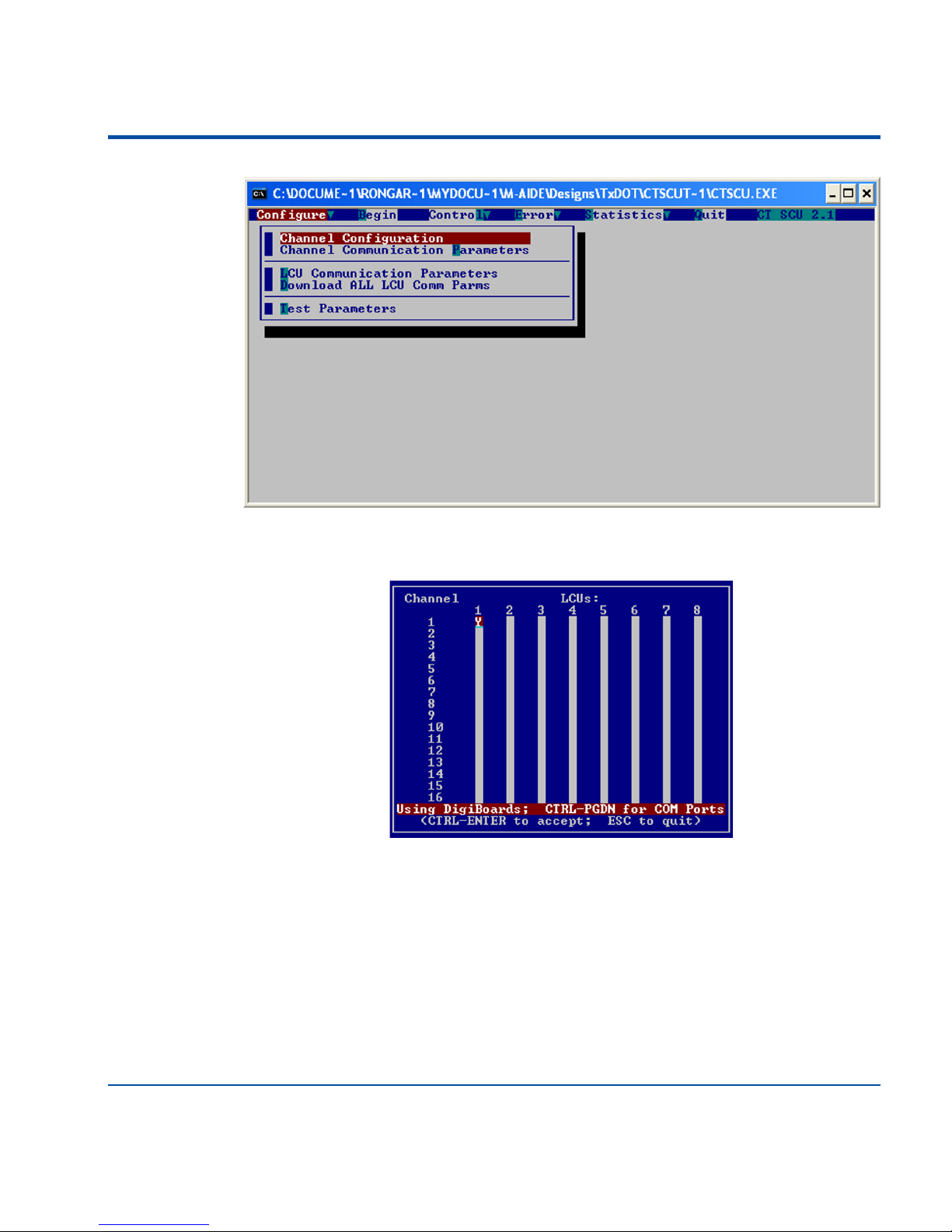
1. A screen similar to the following should be displayed at the PC after
launching the CTSCU.exe application.
Page 43
TxDOT Applications - Test Software
37
2. Execute the Configure>Channel Configuration command. A screen
similar to the following will be displayed.
The Channel Number refers to the number of available comm. ports in the
PC. Each of the LCU Numbers must correspond with one and only one LCU
thumb wheel setting. In the example cited above, LCUs 1, 3 and 4 are
included in the network to be tested.
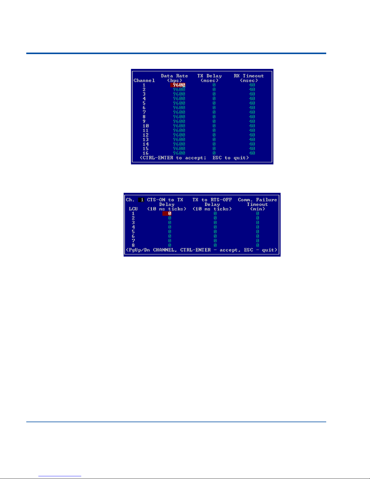
3. Execute the Configure>Channel Communication Parameters command. Accept the default parameters as listed below.
Page 44
LDM User Manual
38
4. Execute the Configure>LCU Communication Parameters command.
Accept the default parameters as listed below.
5. Execute the Statistics>Reset Statistics File. Execute the Error>Reset
Error/Log File command.
6. Execute the Control>Reset All LCUs command. After a brief delay a
message will indicate that the reset was successful.
7. Execute the Control>Download LCU Code to All LCUs command.
After a brief delay a message will indicate that the download was successful.
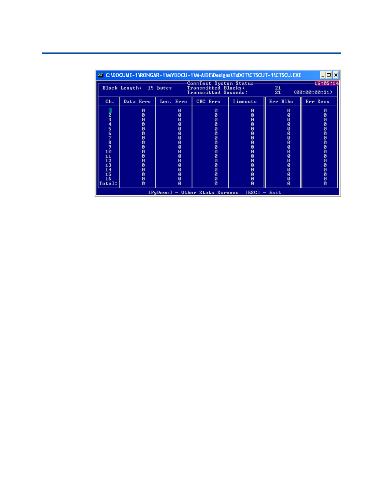
8. Start the test at 9600 Baud by executing the Begin command. Highlight the
command and then press the Enter key twice. The test will start. A display
similar to the following will appear.
Page 45
TxDOT Applications - Test Software
39
The test will run continuously until it is stopped by pressing the Esc key. The
number of test blocks and errors by type will be reported. Run the test in
accordance with the TxDOT acceptance criteria.
Page 46

LDM User Manual
40
USER NOTES
Page 47

Material Return Policy
In the event the customer identifies a malfunction in any product, call or write MICRO-AIDE
and obtain a Return Material Authorization (RMA) number from the customer service department. Return the product to MICRO-AIDE, freight prepaid, with a note (in-warranty repair)
or a purchase order (out-of-warranty) for the repair listing the following information:
• RMA number from MICRO-AIDE
• Return shipment address
• Name and telephone number of person familiar with the problem
• Brief description of the problem (include any printouts that may have a bearing on the problem)
• Method of payment for repair costs (out-of-warranty)
• Send product to the following address:
M
ICRO-AIDE CORP.
685 Arrow Grand Circle
Covina, CA 91722
Tel: 626-915-5502 Fax: 626-331-9484
E-mail: [email protected]
Limited Warranty
MICRO-AIDE warrants its products to be free from defects in material and workmanship for
a period of five (5) years from the date of shipment. This warranty is in lieu of any other warranty, expressed or implied. In no event shall MICRO-AIDE be held liable for incidental or
consequential damage resulting from (1) the use of any of its products, or (2) any alleged
breach of this warranty provision. MICRO-AIDE’s liability shall be limited to repairing or
replacing, at its sole discretion, any defective product which is returned in accordance with the
MICRO-AIDE Material Return Policy.
Product that has been subjected to abuse, misuse, alteration, accident, lightning damage,
neglect or unauthorized installation or repair shall not be covered by this warranty.
MICRO-AIDE reserves the right to make a final decision as to the existence of any failures
and the cause of such failures. No warranty is made with respect to custom equipment or
products produced to buyer’s specifications except as mutually agreed upon in writing.
Page 48

MICRO-AIDE CORP.
685 Arrow Grand Circle
Covina, CA 91722
Tel: 626-915-5502 Fax: 626-331-9484
E-mail: [email protected]
 Loading...