

Page 1
ASSEMBLY GUIDE
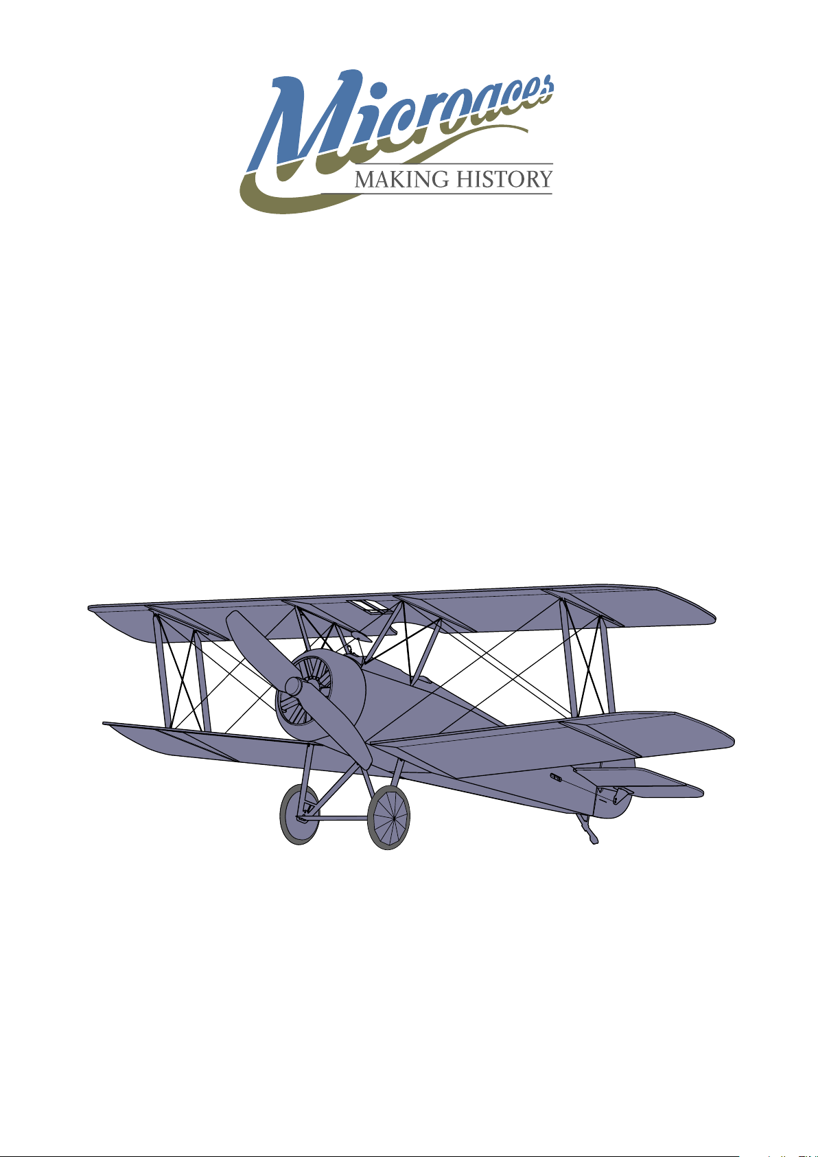
Sopwith F.1 Camel
Page 2
Introduction
Thank you for purchasing this Microaces Aero Kit. Designed using innovative ideas,
advanced materials and detailed aircraft illustrations, this 1/24th scale aircraft will bring
you hours of building enjoyment and many more exciting ying hours too. Please take
your time to familiarise yourself with these instructions as the aircraft assembles in a
very unique way, following a sequence of steps that should be adhered too to ensure a
satisfactory and yable model.
Safety
Assembly
Warranty
Key
It is extremely important to us that you and those around you remain safe while building
and ying Microaces kits. Please take note of the following notices of safety. Microaces
Aero kits contain parts and packaging unsuitable for handling by small children. Please
ensure that children under the age of 6 years are prevented from handling the component
parts or packaging of this kit. Although the resulting model is lightweight, we DON’T
recommend that you y it near or over others where there is a danger of striking someone.
We DO recommend that the maiden ight is performed over long grass in calm weather
away from others.
Read all the instructions carefully before starting assembly.
It is important to use the recommended glues or an equivalent with similar properties.
Foam parts must be glued with a foam safe cement or permanent damage can result to
components. Ensure your knife has a fresh or sharp blade installed to ensure a clean cut.
Microaces warranties this kit is supplied with all components present and that those
components are free from cosmetic or structural damage to an extent that would impair
the assembly of the kit, alter the aesthetics of the built model and/or the ight performance
of the resulting model. If any parts are missing or damaged please contact us via email at:
[email protected]
Note (Information)
Attention
P01
Part Number
Contact Adhesive (Foam Safe)
Alphatic Resin (or Foam Safe CA)
Paint
Area of adhesion for glue
2
Do Not Glue
Score before assembly
Cut
Sanding Required
Page 3

KIT PARTS
Sheet Parts 1 x 2mm Laser cut Depron airframe
1 x 1mm printed & laser cut Depron fuselage
1 x 1mm printed & laser cut Depron ight surfaces
1 x 200 micron printed & laser cut polypropylene
1 x polyester sticker sheet
1 x 0.8mm laser cut plywood motor mount parts
Loose Parts
RECOMMENDED TOOLS/GLUES
2 x neoprene tyres
2 x 4mm Ø plastic tube (Black)
2 x 4mm Ø x 1mm noedymium magnets
1 x 110mm x 0.4mm x 1mm carbon bre strip
1 x 390mm x 0.4mm x 1mm carbon bre strip
1 x 70mm x 1mm Ø carbon bre rod
1 x piano wire elevator control rod
1 x piano wire rudder control rod
1 x prole pilot gure
1 x Spectra rigging wire
1 x 3D printed fuel prop
1 x 3D printed rigging guide
1 x Brass tube 2mm Ø x 12mm
Knife or Scalpel with fresh blade
Steel Rule or straight edge
Sanding Stick or sand paper (180 grit recommended)
Tweezers
Needle nose pliers
UHU por foam safe adhesive (For foam & plastic)
Aliphatic Resin or Foam safe cyano glue (for rigging & re-inforcement)
3
Page 4
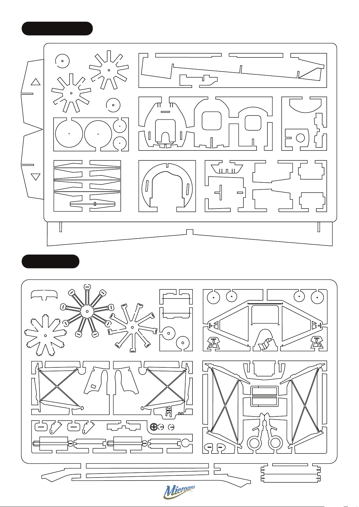
2mm DEPRON FOAM
D20
D19
D19
D1
D10
D16
D17 D17
D16
PLASTIC PARTS
D14
D14
D14
D12
D20
D18
D18
D15
D3
D2
D11
D9
D8
D4
D7
D7
D3b
D13
D5
D6
D6
P13
P28
P29
P31
P15
P8 P9
P11 P16 P11 P16
P6 P7 P10
P1
P30
P17
P32
P18
P32
P22 P22P23 P23
P34
P19
P20 P21
P26
P12
P33
P5 P5 P4
P2
P3
P14
P27
P25
P24
4
Page 5
1mm DEPRON FOAM
Z14 Z14 Z10
Z2
Z11
0.8mm PLYWOOD
Z1
Z9
Z12 Z12
5
Page 6
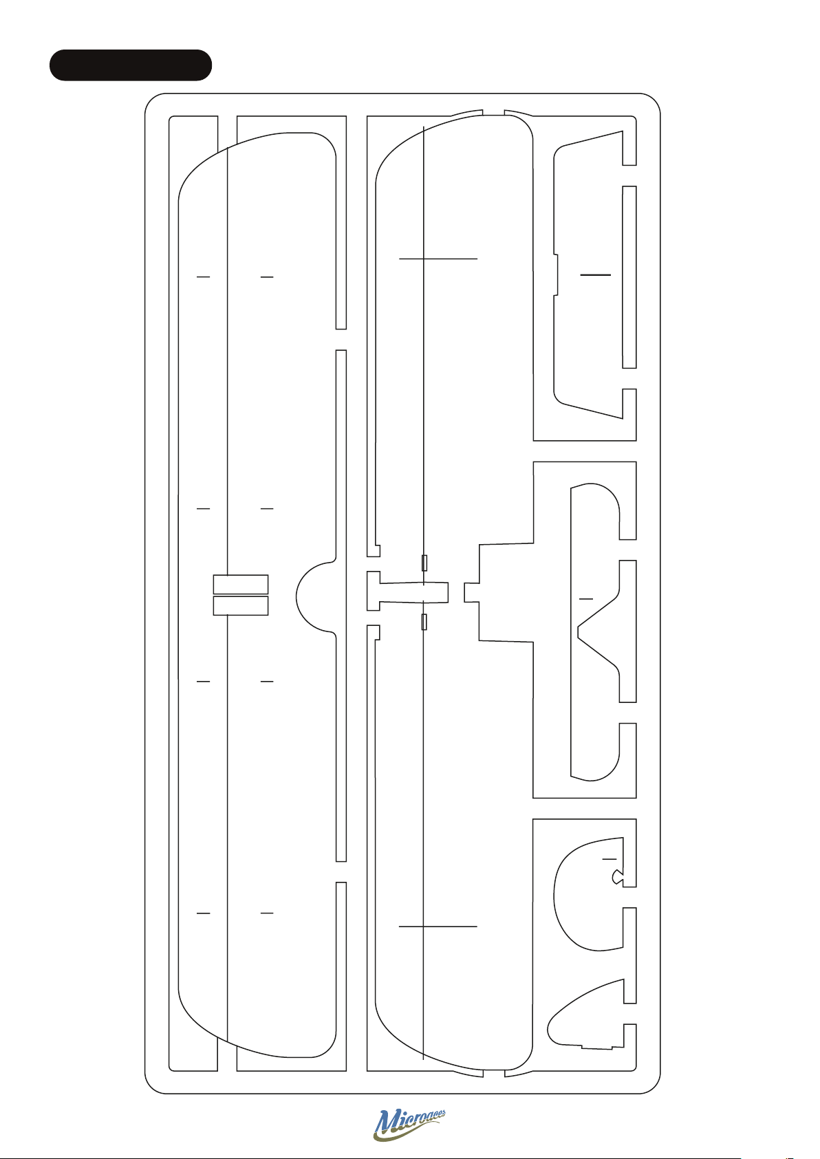
1mm DEPRON FOAM
Z8
Z13
Z5 Z6 Z4 Z3
Z7
6
Page 7
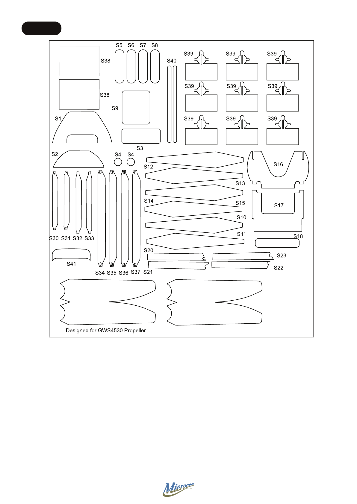
STICKERS
7
Page 8
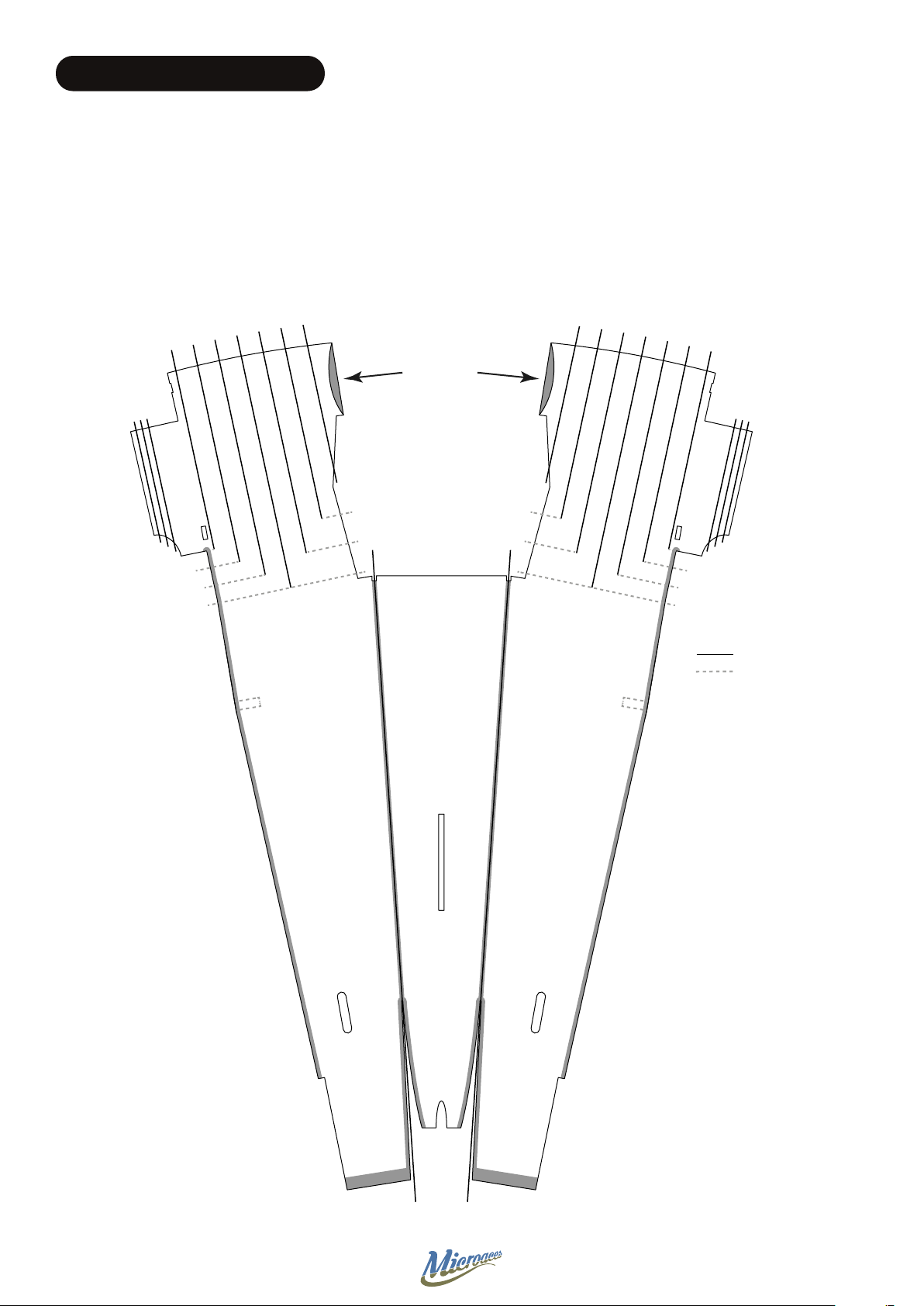
SCORING & BEVELING GUIDE #1
Method for scoring 1mm Depron
Using a straight edge as a guide, score the depron with the reverse side of a craft knife or a ball point pen.
If you haven’t used this technique before it is essential that you practice using a scrap or spare piece of 1mm
Depron prior to processing any kit components.
Always score on the UNPRINTED side of
the Depron unless otherwise directed
SCORE
!
SCORE
REMOVE
SCORE SCORE
RE
SCO
Z1
Position of
D3b
Drawn to scale: Print without scaling and use for scoring parts indicated
SCORE
KEY
Score Lines
Visual Guide Lines
(Do Not Score)
Position of
D3b
Bevel 45°
Bevel 45°
Shallow
Bevel
Bevel 45°
SCO
RE
Shallow
S
Bevel
C
O
R
E
8
Page 9
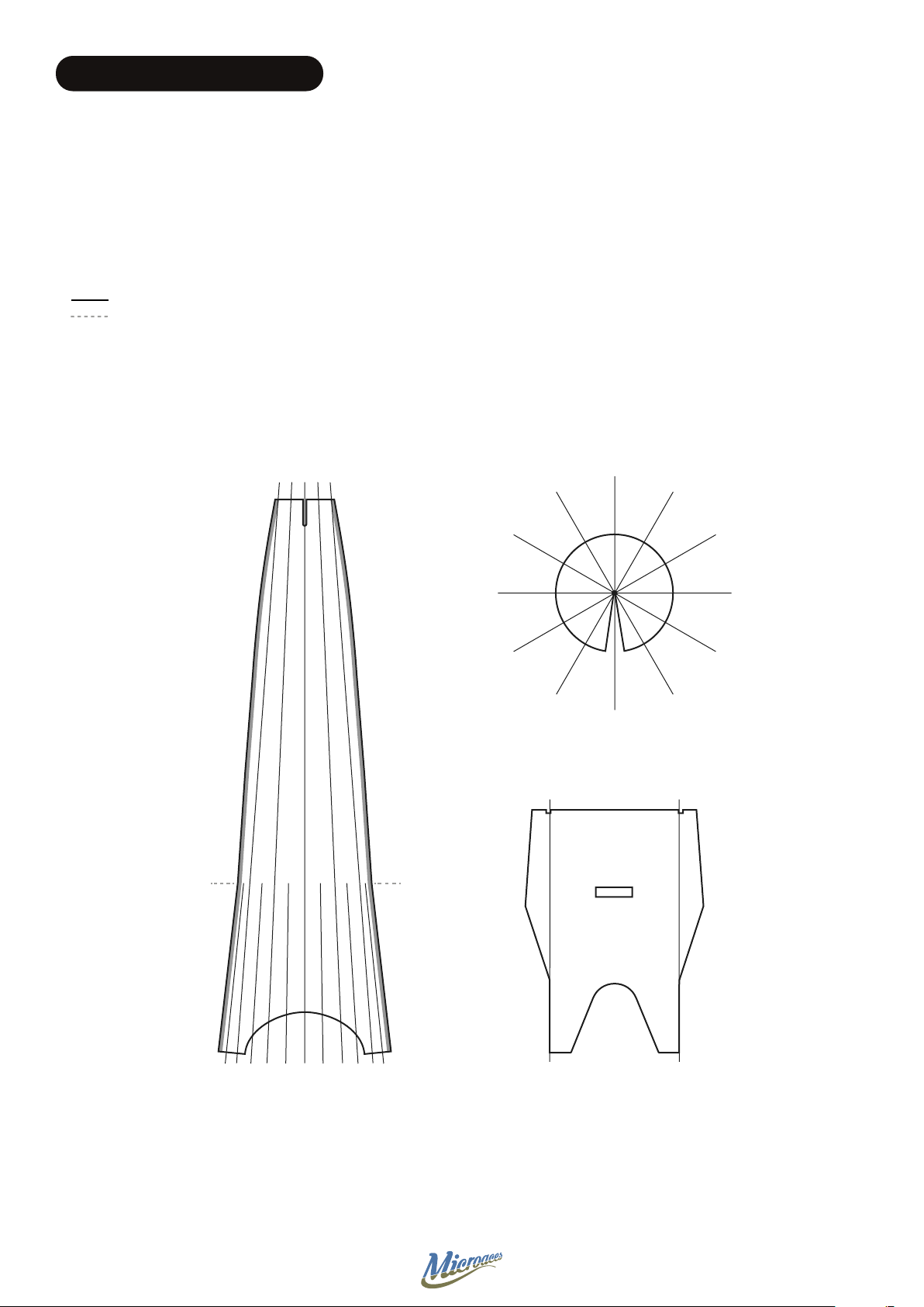
SCORING & BEVELING GUIDE #2
Method for scoring 1mm Depron
Using a straight edge as a guide, score the depron with the reverse side of a craft knife or a ball point pen.
If you haven’t used this technique before it is essential that you practice using a scrap or spare piece of 1mm
Depron prior to processing any kit components.
KEY
Score Lines
Visual Guide Lines
(Do Not Score)
Always score on the UNPRINTED side of
the Depron unless otherwise directed
!
SCORE
Z11
X2
Bevel 45°
SCORE
Z2
Bevel 45°
SCORE SCORE
Z9
SCORE
9
Page 10
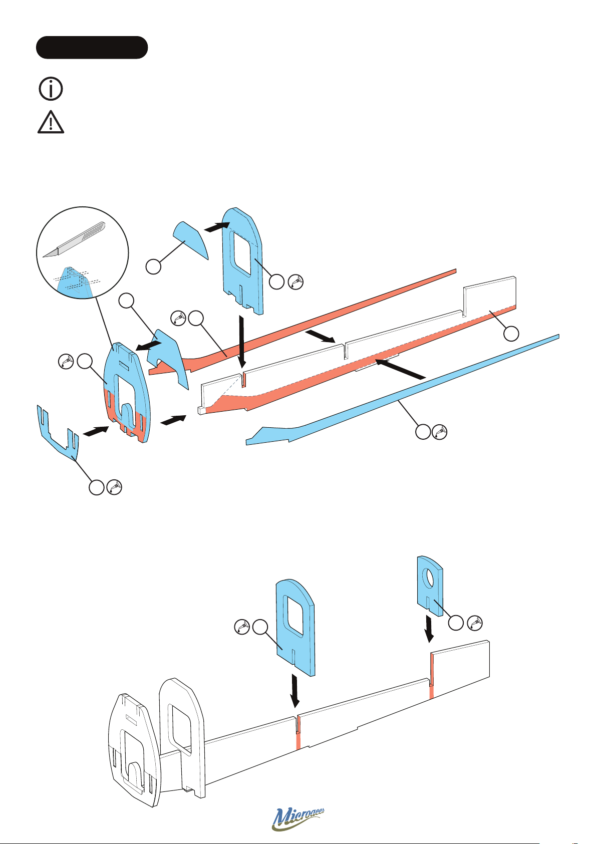
STAGE 1 AIRFRAME
The plastic parts used in the airframe are there to increase the strength of the structure in vital areas
whilst still providing some exibility.
Apply a thin layer of adhesive to the plastic part and attach immediately to allow some wiggle
time to get the parts lined up. Set aside to cure.
S2
D3
S1
P1
D1
D2
P3
D4
P2
D5
10
Page 11
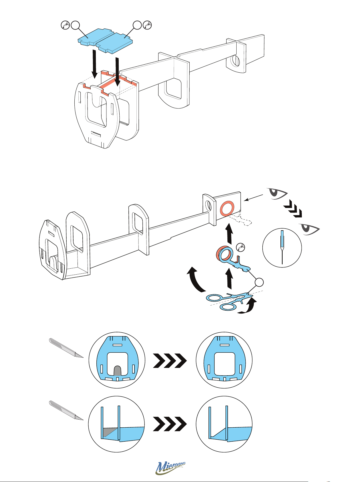
D6
D6
D2
D1
P4
D2
D1
11
Page 12
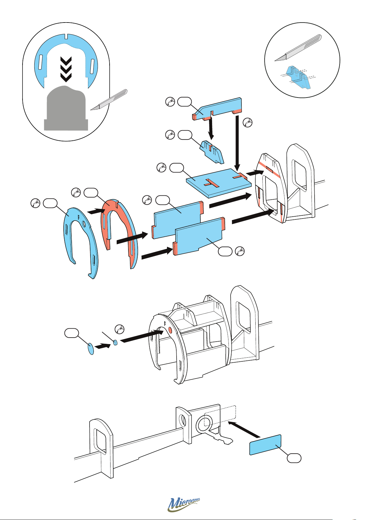
W1
D11
D9
D10
D9
D8
D11
D7
S4
D7
Magnet
12
S3
Page 13
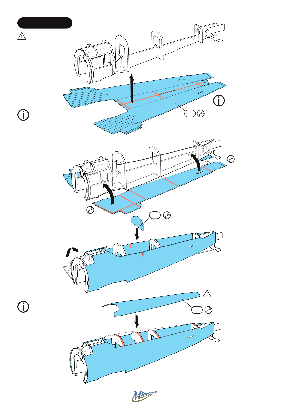
STAGE 2 FUSELAGE
Dry t before gluing
Pre-bend scored areas on
part prior to installation to
make tting easier.
Z1
Bevel & Score before
installation - See
Scoring & Bevelling
guide #1
Pre-bend scored areas on part
prior to installation to make
tting easier.
D3b
Dry t before gluing
Z2
13
Page 14
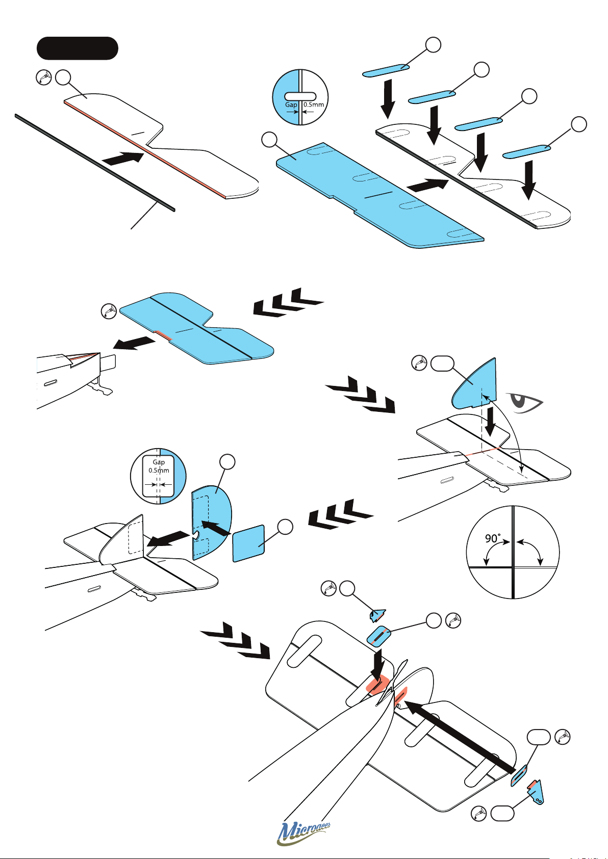
STAGE 3 TAIL
==
S5
Z4
Carbon Fibre
110mm x 1.0mm x 0.4mm
S6
S7
S8
Z3
Z5
Z6
90˚
S9
P9
P8
P6
P7
14
Page 15
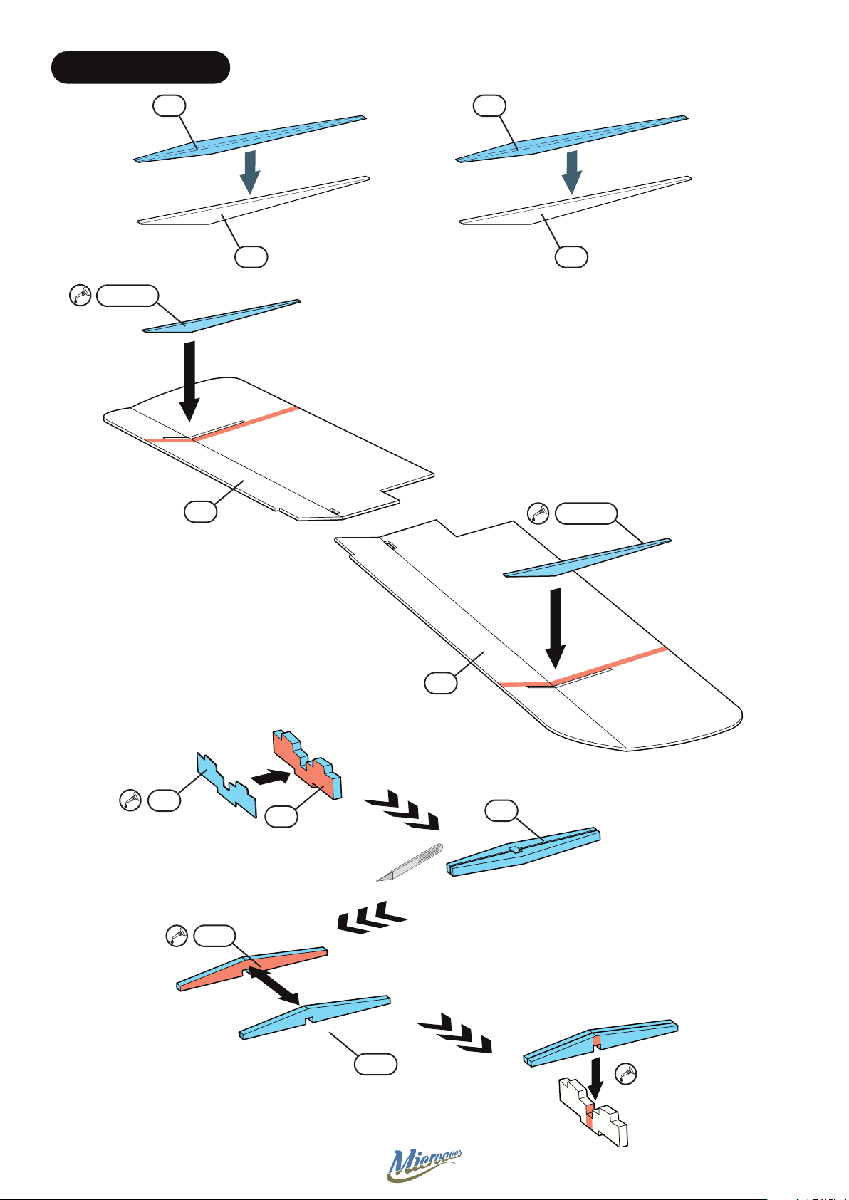
STAGE 4 LOWER WING
S11 S10
D14/S11
D14 D14
P10
Z8
D13
D14/S10
Z7
D12
D12
D12
15
Page 16
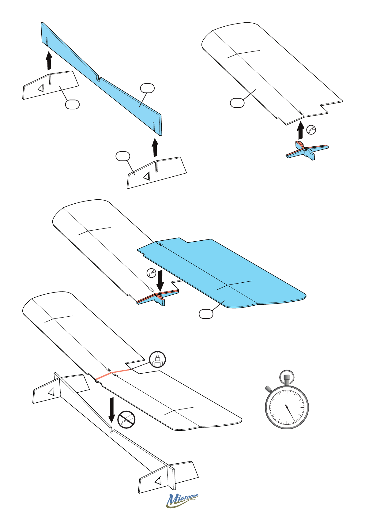
Z15
Z16
Z7
Z16
Z8
Time
1 Hour
16
Page 17
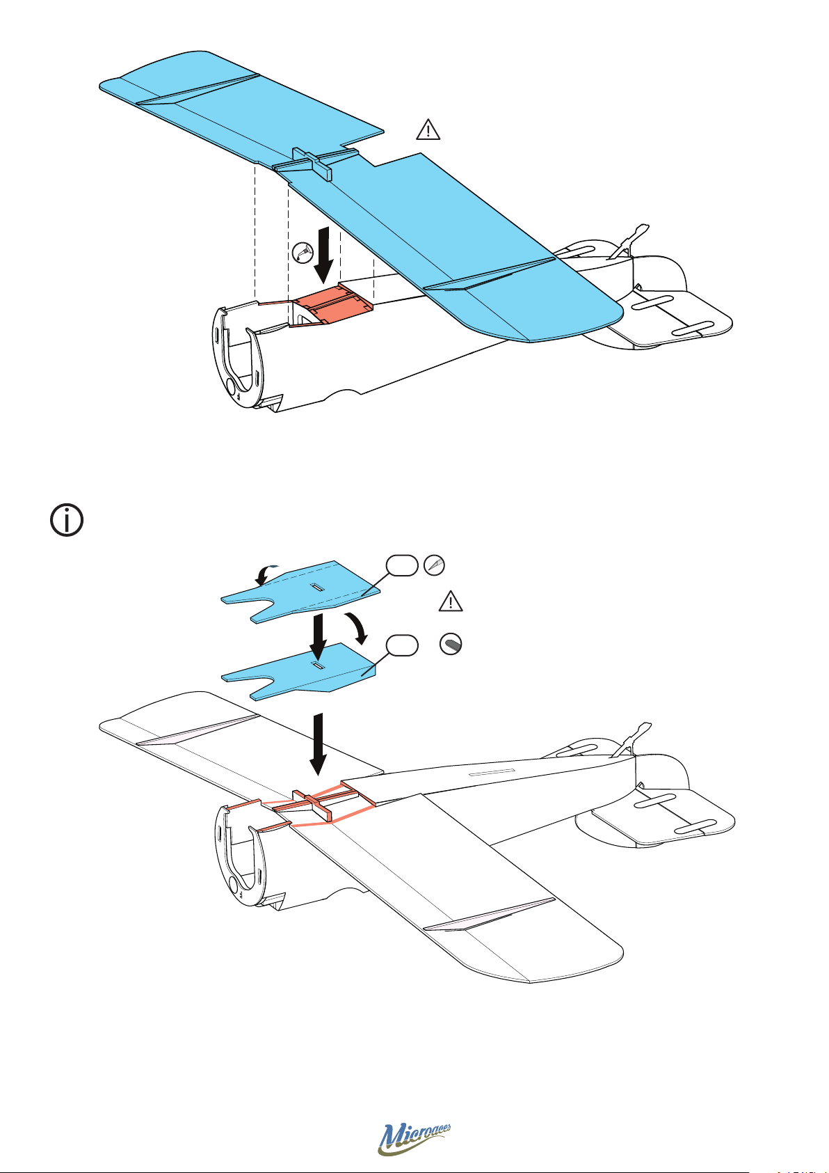
Pre-bend scored areas on part
prior to installation to make
tting easier.
Dry t before gluing
Z9
Z9
Dry t before gluing
Some sanding may be
required for best t
17
Page 18
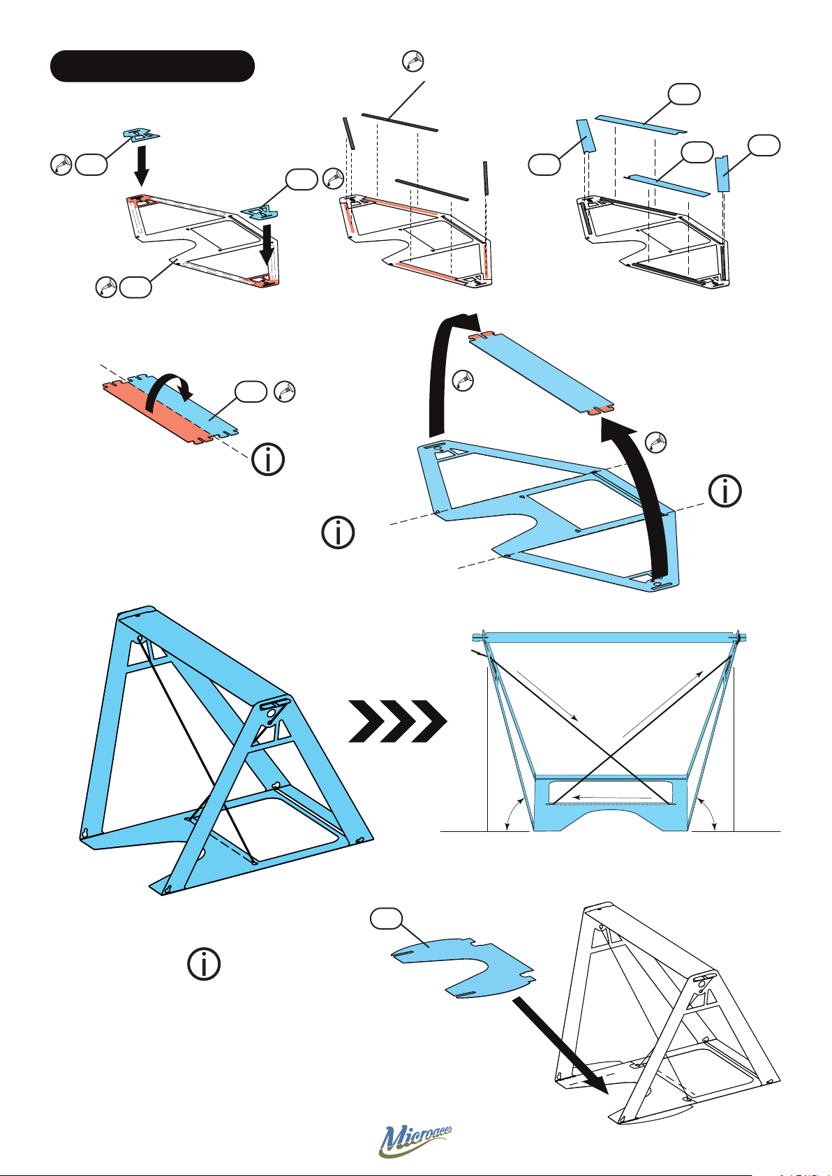
STAGE 5 UNDERCARRIAGE
Carbon Fibre
31mm x 1.0mm x 0.4mm
4 o
S21
P21
P19
P24
P20
Fold
Fold
S22
S20
S23
Fold
Complex Stickers can
be applied by wetting
the adhesive side to aid
positioning
S16
A
Rear
BC
Front
D
* ˚=* ˚=
a
d
c
18
b
Page 19
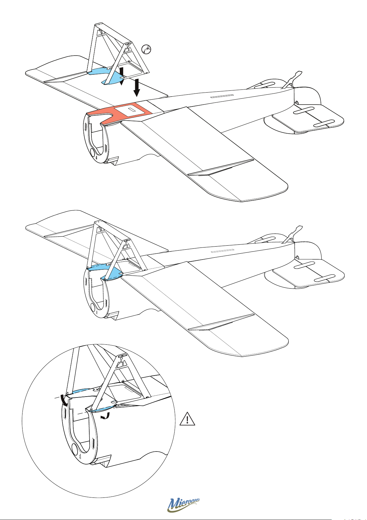
Fold side stickers down into gap
19
Page 20
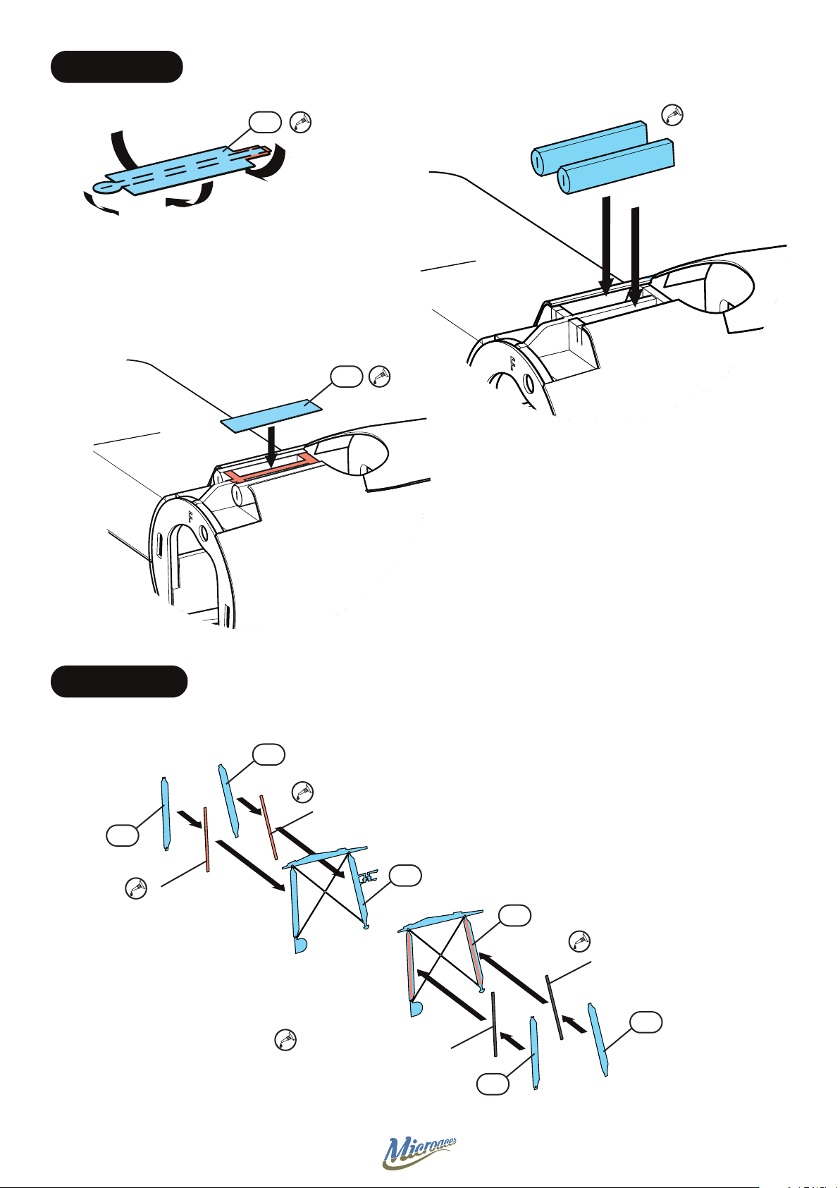
STAGE 6 DETAIL
P11
X2
Z10
STAGE 7 STRUTS
S31
Carbon Fibre
30mm x 1.0mm x 0.4mm
S33
Carbon Fibre
32mm x 1.0mm x 0.4mm
P12
P13
Carbon Fibre
32mm x 1.0mm x 0.4mm
S32
Carbon Fibre
30mm x 1.0mm x 0.4mm
S30
20
Page 21
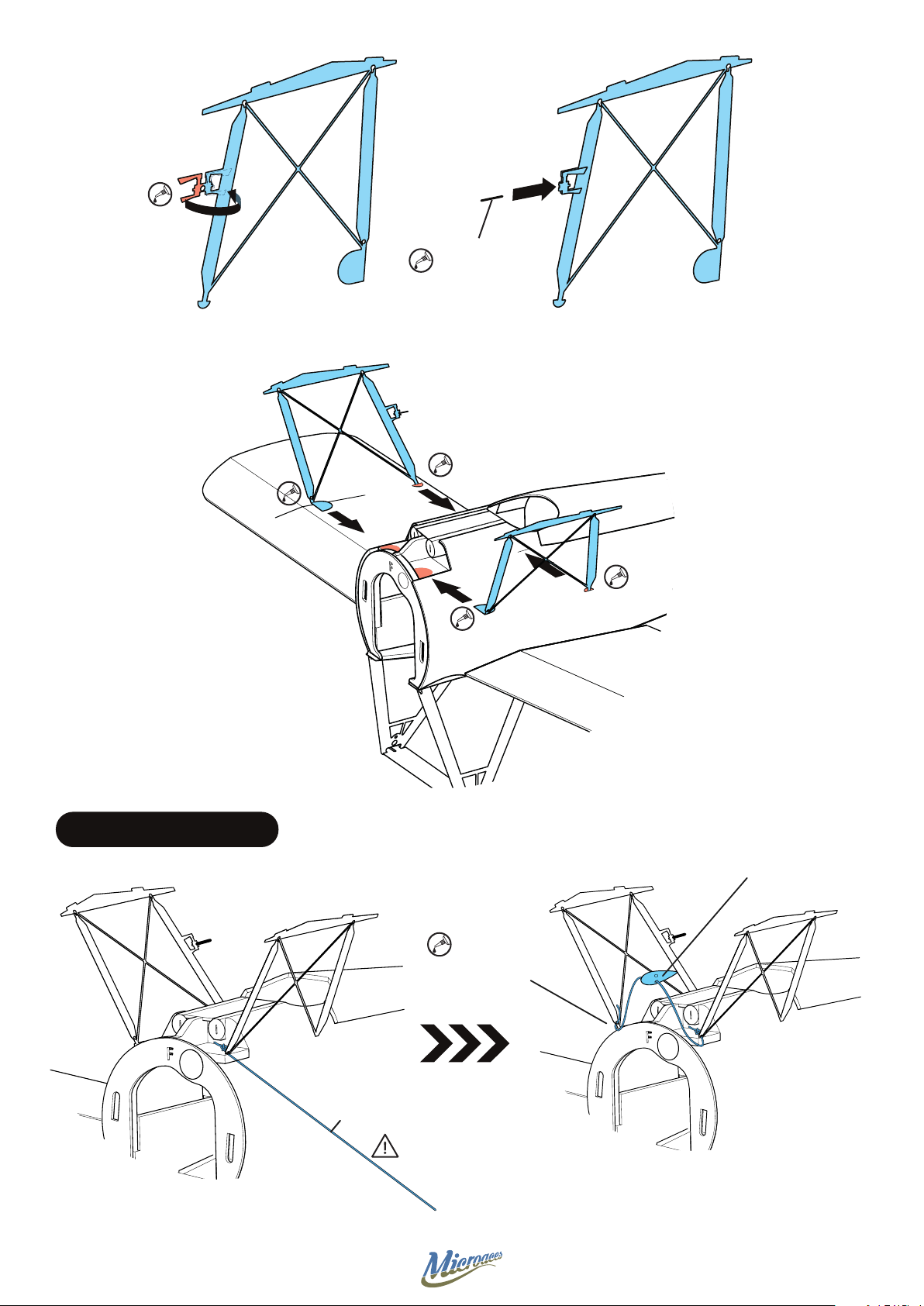
Piano Wire
6mm Long
STAGE 8 RIGGING FAIRING
3D printed
Rigging guide
Glue at 50mm
marker and trim
excess
Mark 50mm with
a marker pen
Rigging Wire
21
Page 22
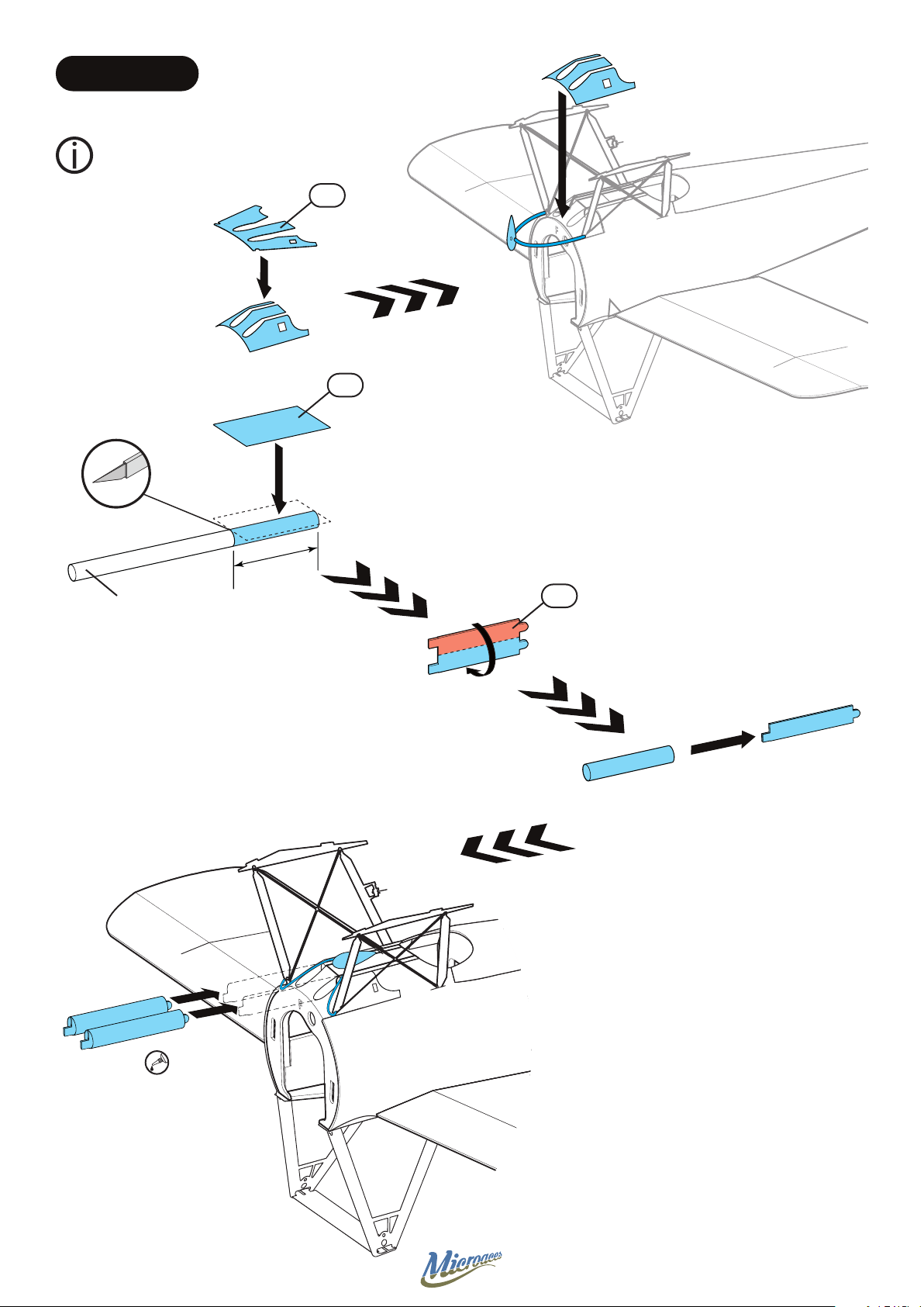
STAGE 9 DETAIL
Shape the forward cowling
P15 before installing.
P15
S38
4mm Ø plastic tube
(Black)
23mm
P16
X2
22
Page 23
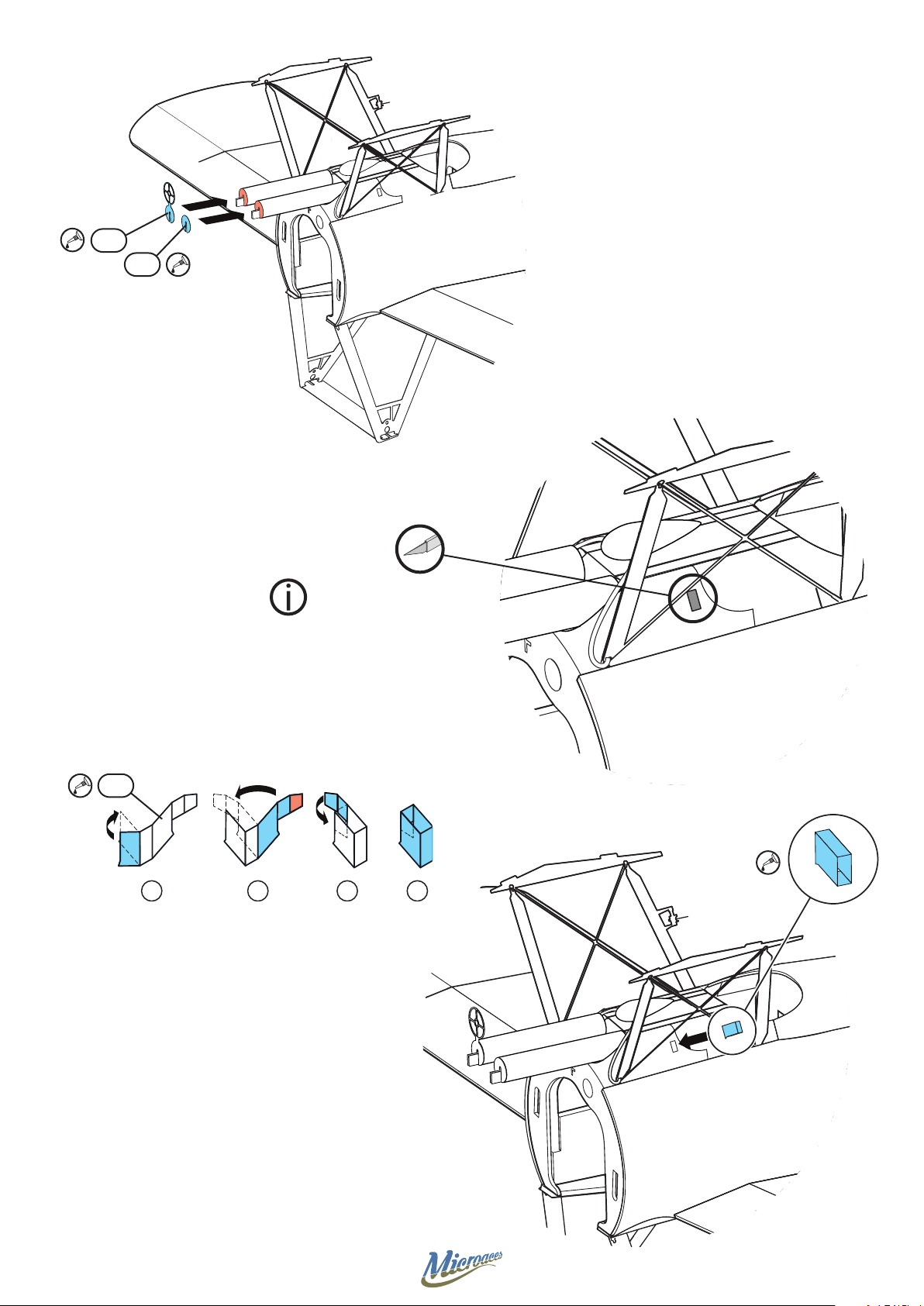
P17
P18
Remove indicated area
P14
1 2 3 4
23
Page 24
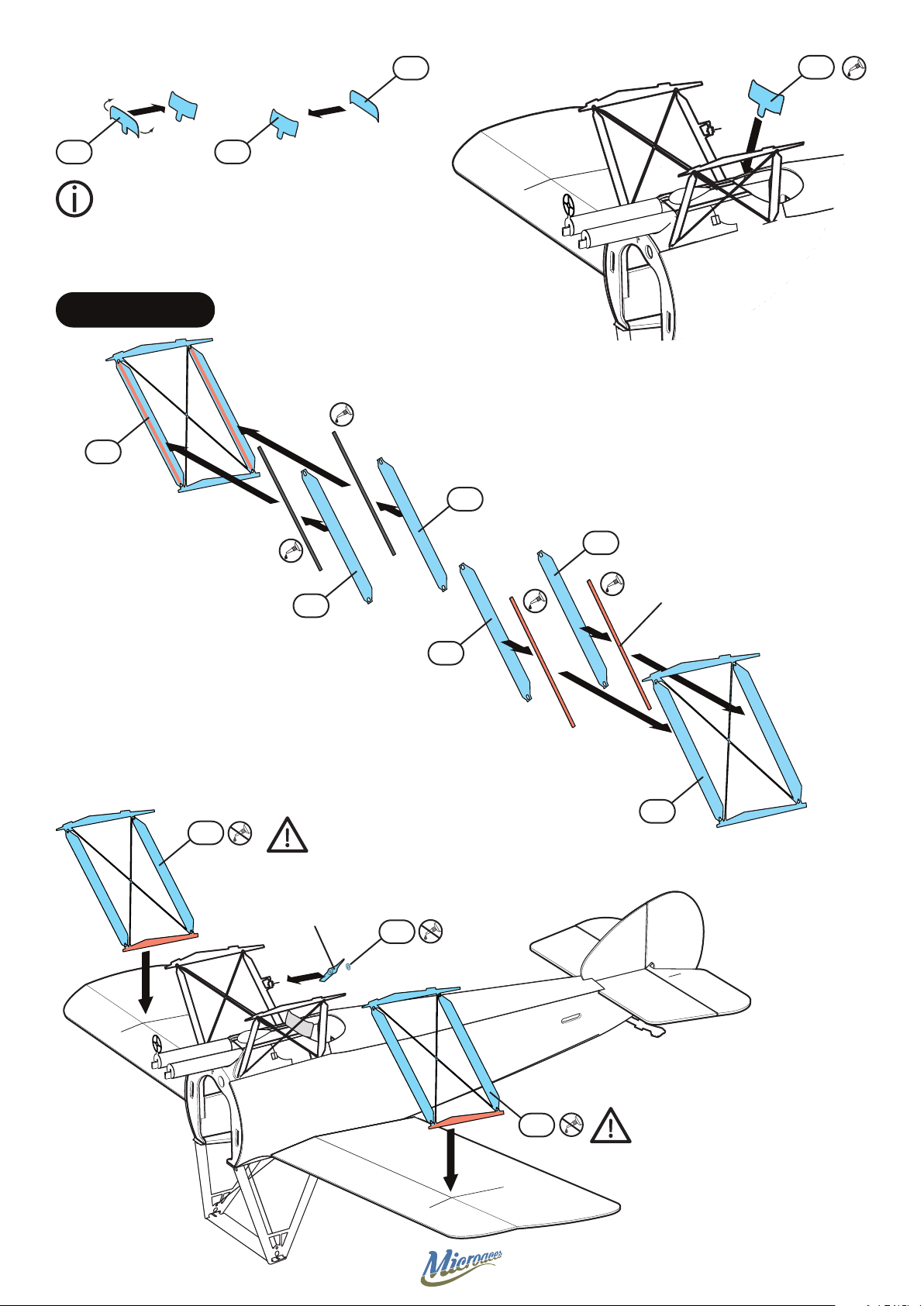
S41
P28
P28
Bend the windshield P28
before applying sticker S41
STAGE 10 STRUTS
P27
P28
S36
S37
S35
Carbon Fibre
53mm x 1.0mm x 0.4mm
4 OFF
P27
S34
P26
Do NOT glue struts until stage 12
Fuel Prop
P33
24
P26
Do NOT glue struts until stage 12
Page 25
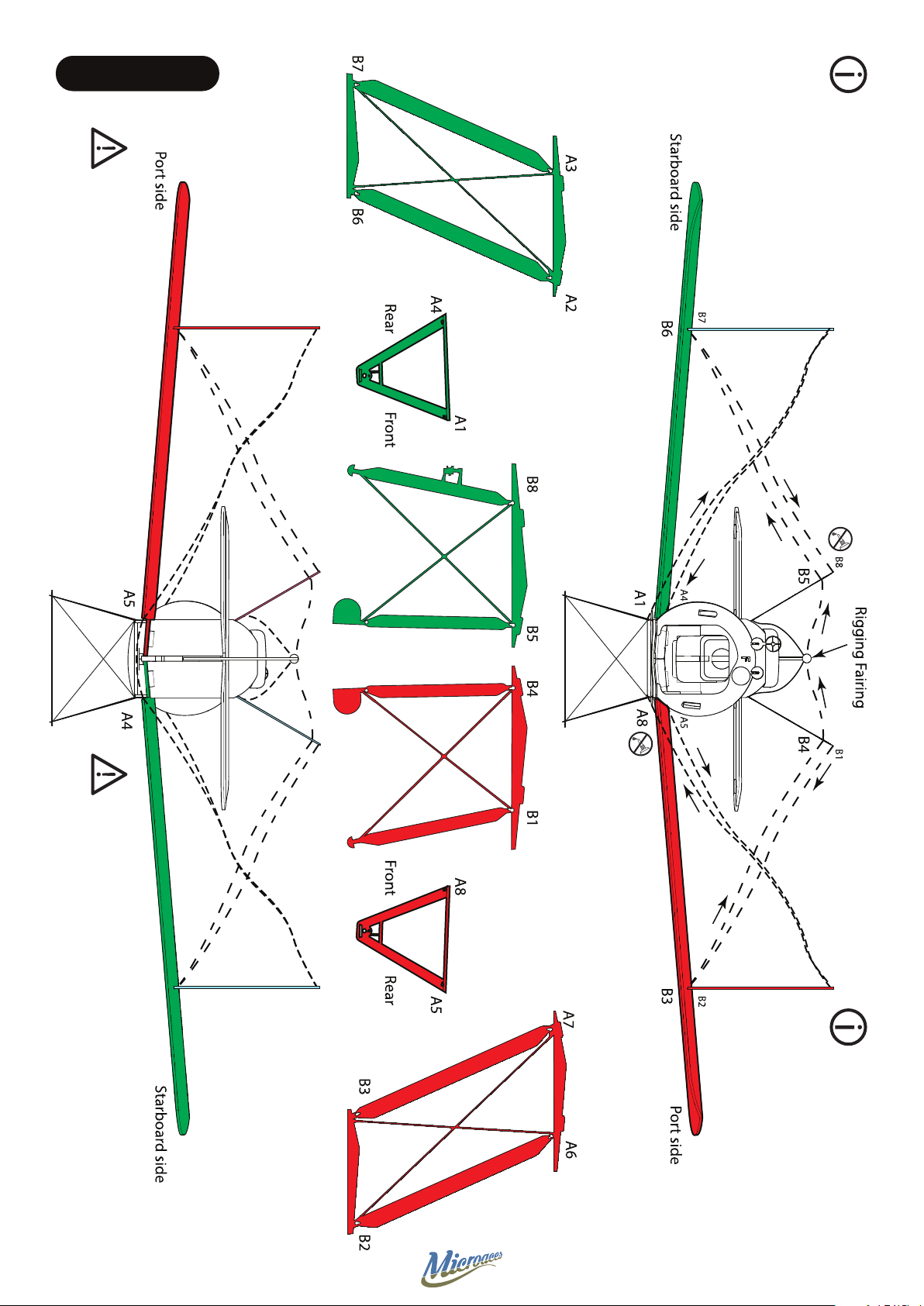
STAGE 11 RIGGING
Follow sequence A1 to A8 using 700mm of rigging wire Follow sequence B1 to B8 using 700mm of rigging wire
Use a rigging tool or needle
threader to pass rigging wire
through pre-cut holes.
25
Leave a tail out at A8 & B8
from both rigging runs for
tightening later.
Page 26
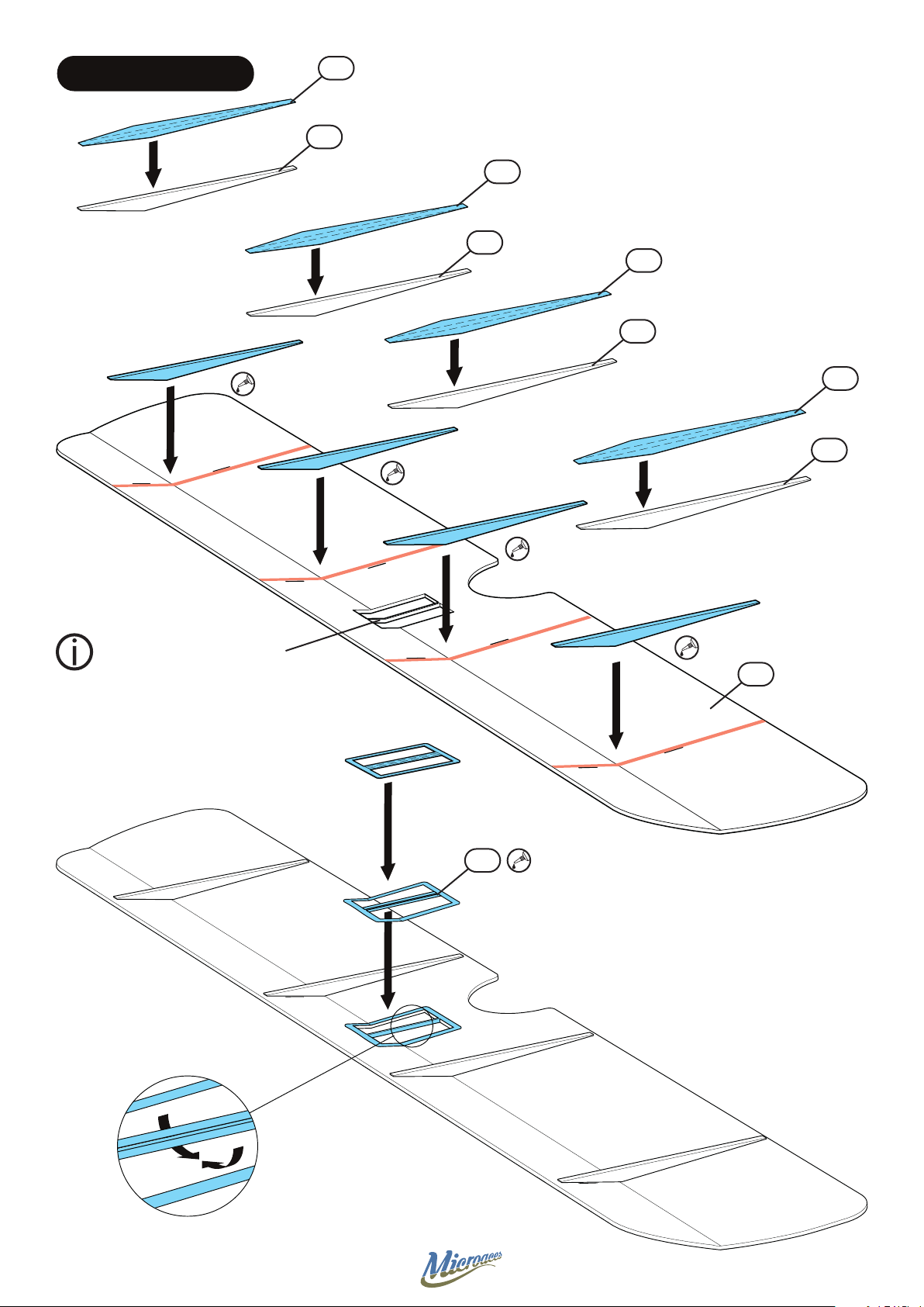
STAGE 12 UPPER WING
S14
D14
S12
D14
S13
D14
S15
D14
Cut out window from wing
before folding
Z13
P27
26
Page 27
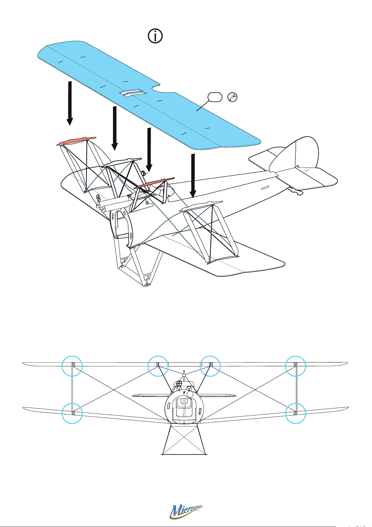
Interplane
Mounting the Wing
Ensure the tabs on the top of the strutwork insert fully into the
corresponding slots in the wing. Secure and allow adhesive to set.
Z13
Cabane
Cabane
Interplane
27
Page 28
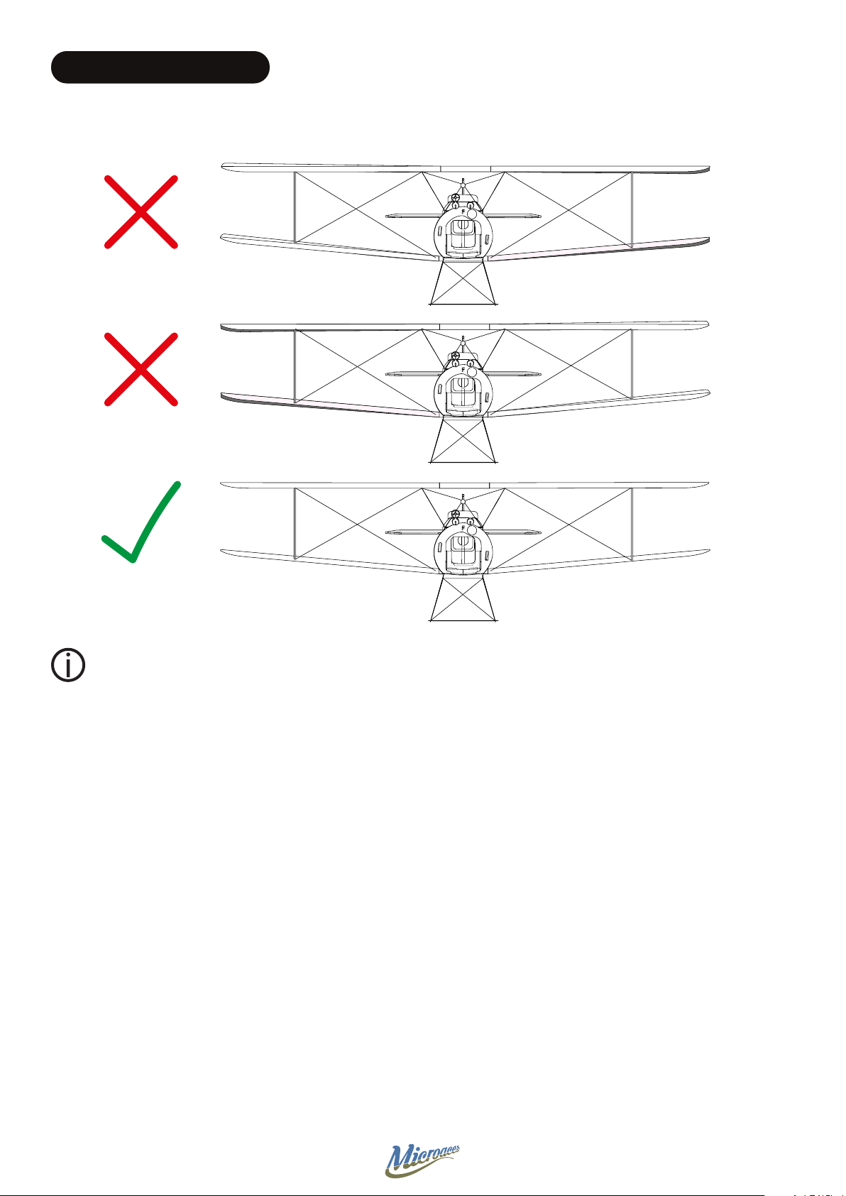
STAGE 13 RIGGING TENSION
FRONT VIEW
Ensure correct alignment when tensioning the rigging
The rigging on the Sopwith Camel is functional. It strengthens and stabilises the wings to provide predictable
ight characteristics so is important to get right!
Tension the wire between struts. Because of the shape of the laser cut holes in the struts, you can lock the
thread at each point that it passes through a rigging hole.
Work on tensioning the wire on both sides of the aircraft simultaneously to help maintain symmetry.
Secure the end points of the rigging to the underside of the wing once happy with the tension using foam safe
CA or Aliphatic resin.
Check alignment visually then add a small amount of adhesive to each point where the rigging passes through
strut work.
Trim excess rigging with a fresh blade.
Glue bottom of both Interplane struts to lower wing ribs.
28
Page 29
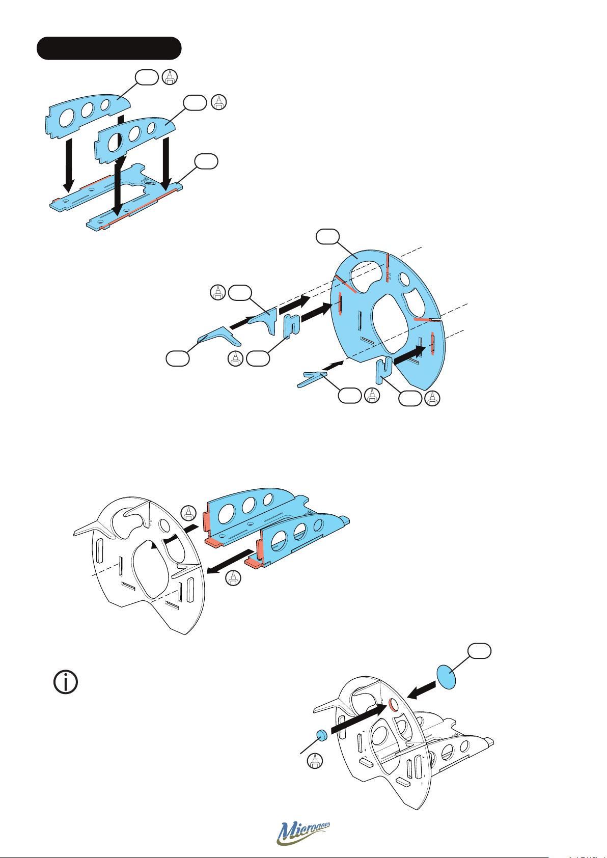
STAGE 14 MOTOR MOUNT
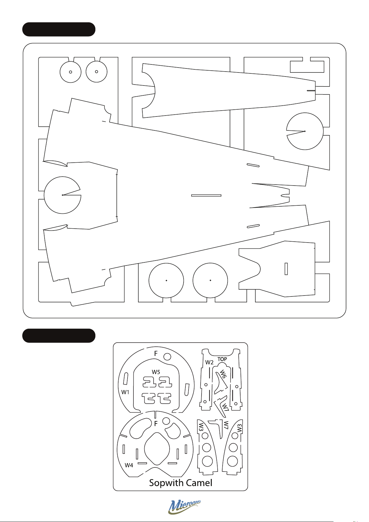
W3
W3
W2
W4
W6
W7
W5
W7
W5
S4
Ensure the magnet is correctly oriented
before installation. Do this by matching it to
the magnet installed in the fuselage rewall
before installing it here.
Magnet
29
Page 30
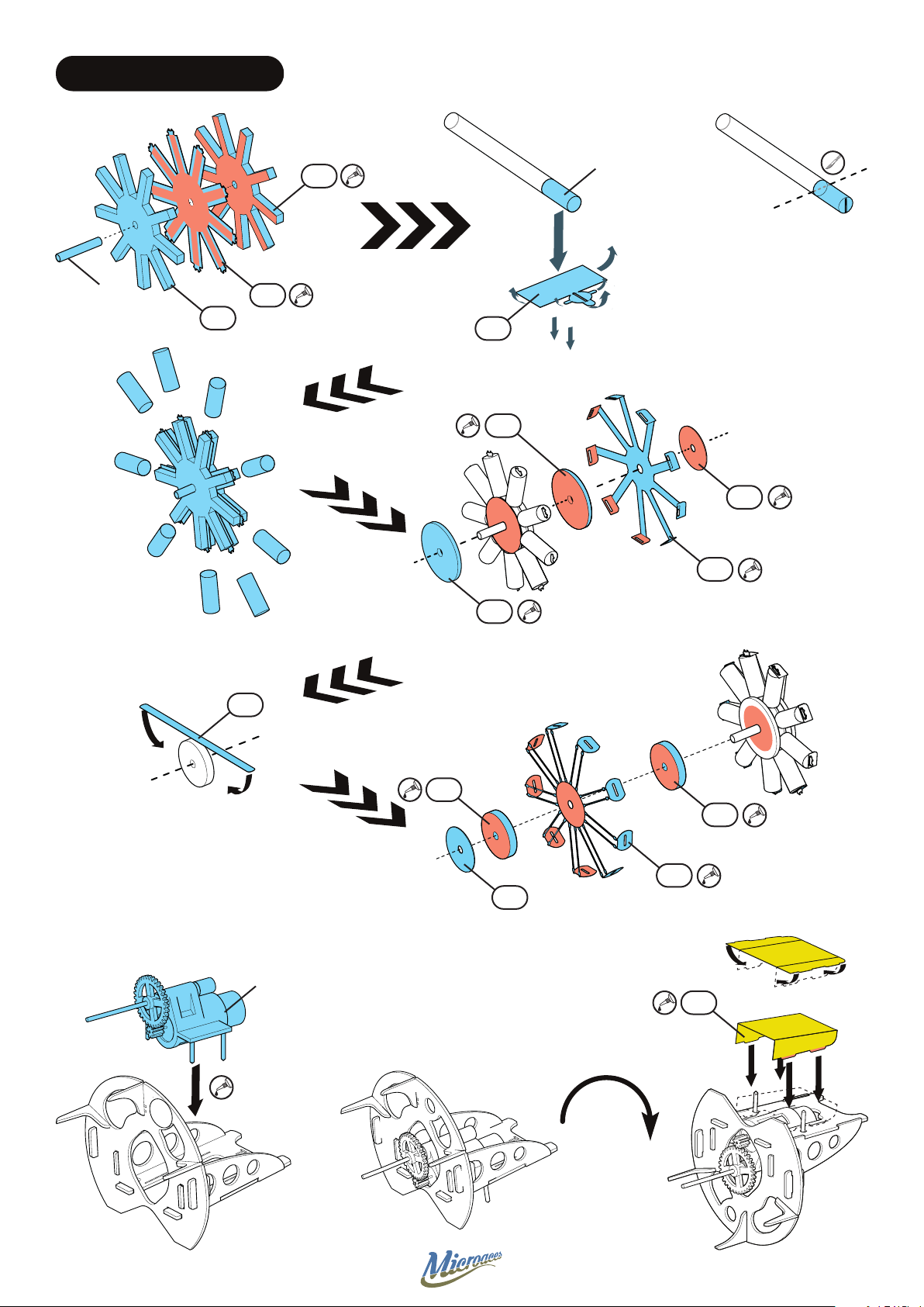
STAGE 15 ROTARY ENGINE
Straw 4mmØ
D19
x9
Brass Tube
2mmØ x 12mm
D19
S40
P29
S39
Z14
P32
P30
Z14
x2
x2
Motor Gearbox
(Long Shaft)
D20
D20
P31
P32
P34
30
Page 31
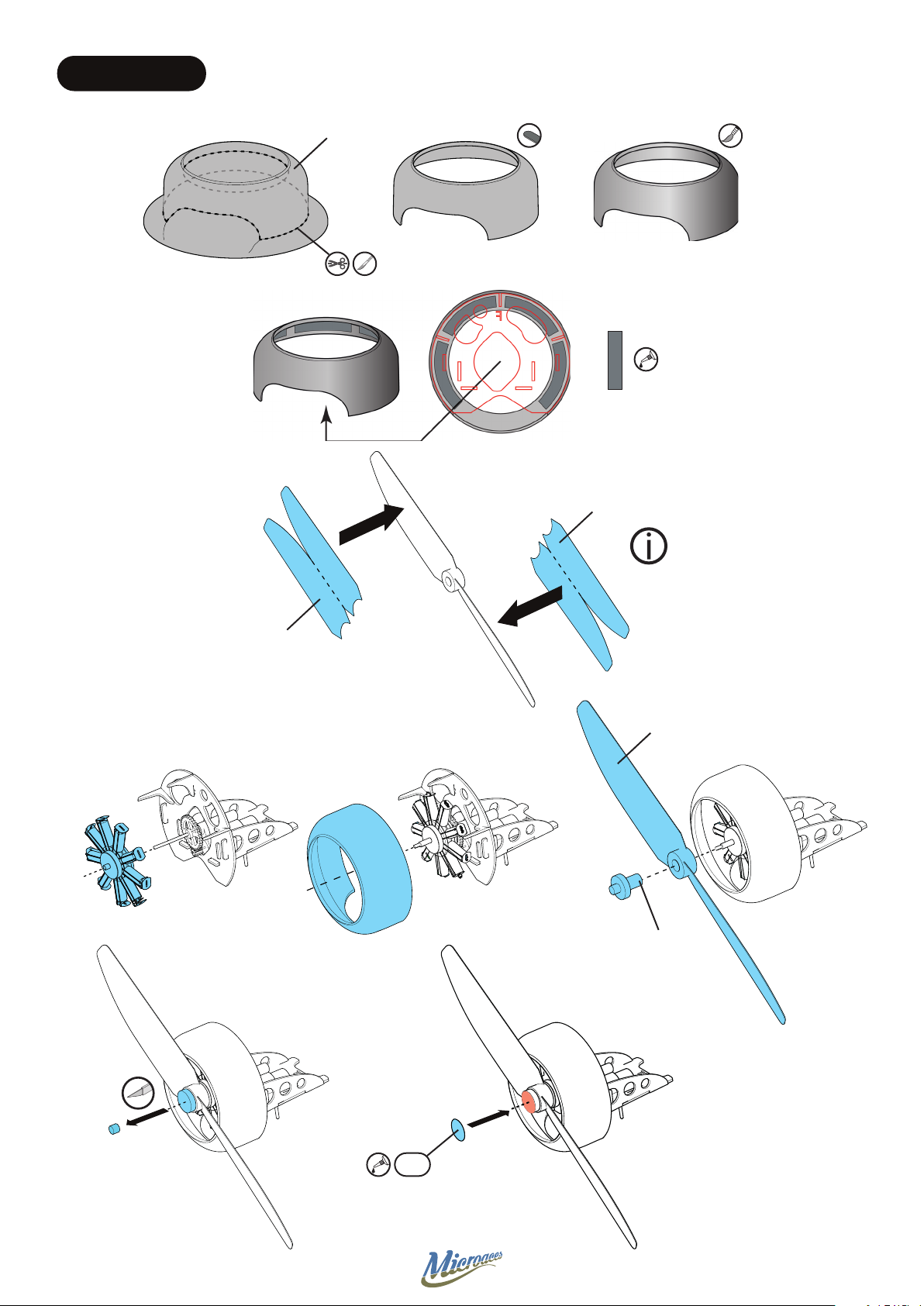
STAGE 16 COWL
Cowl
Prop
Sticker
Ballast
Lead
Ballast x 4
Prop
Sticker
Complex Stickers can
be applied by wetting
the adhesive side to aid
positioning
Propeller
P33
Prop Adapter
31
Page 32
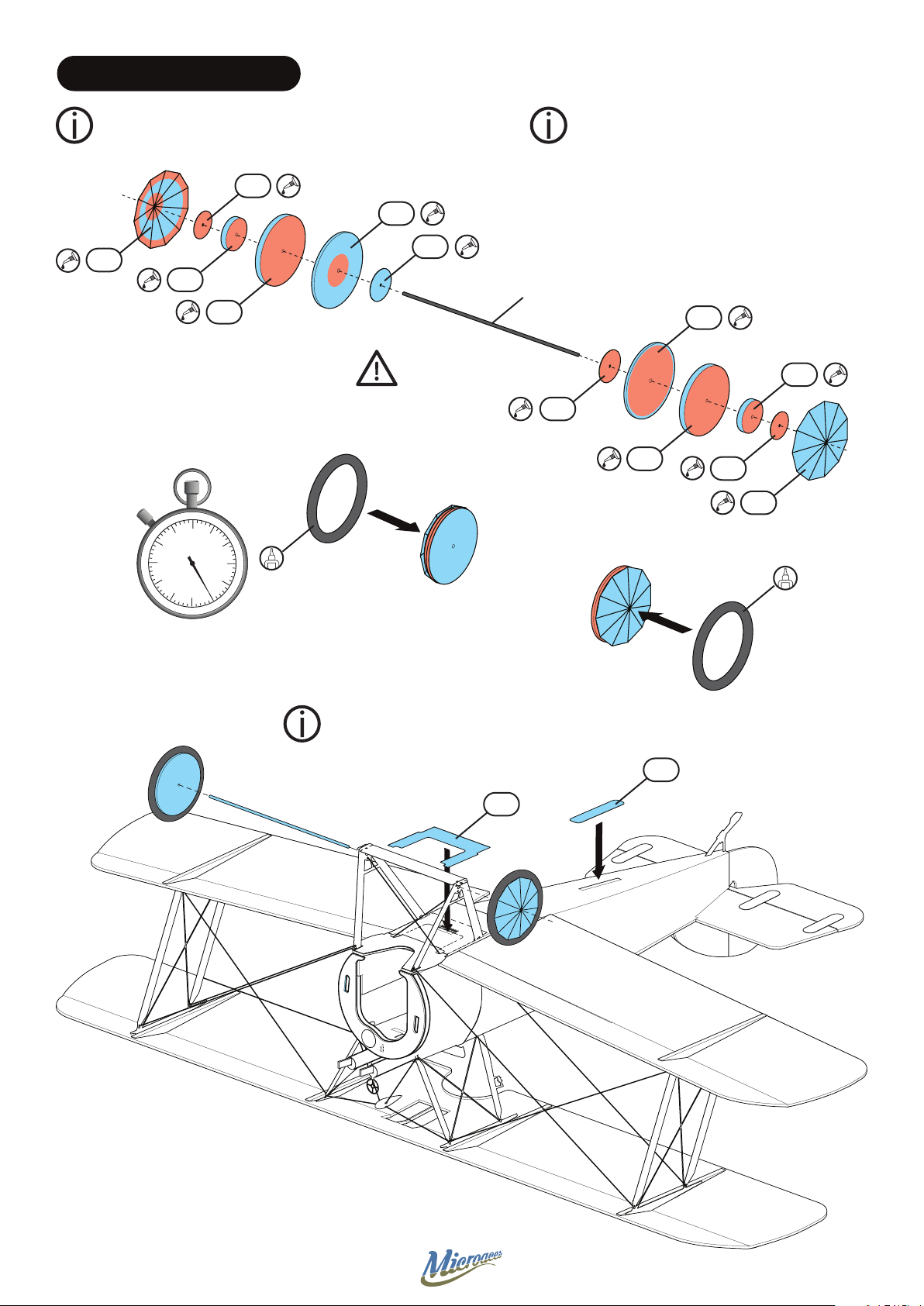
STAGE 17 WHEEL ASSEMBLY
Bevel & Score Z11 before installation See Scoring & Bevelling guide #2
P23
Z11
D18
D17
Z12
P22
Carbon Fibre
1mmØ x 70mm
DO NOT GLUE TO
AXLE AT THIS STAGE
Assemble each wheel onto the axle
temporarily to ensure good alignment.
Z12
P22
D17
P23
Z11
D18
Time
2 Hour
Complex Stickers can be applied by wetting
the adhesive side to aid positioning
S18
S17
32
Page 33
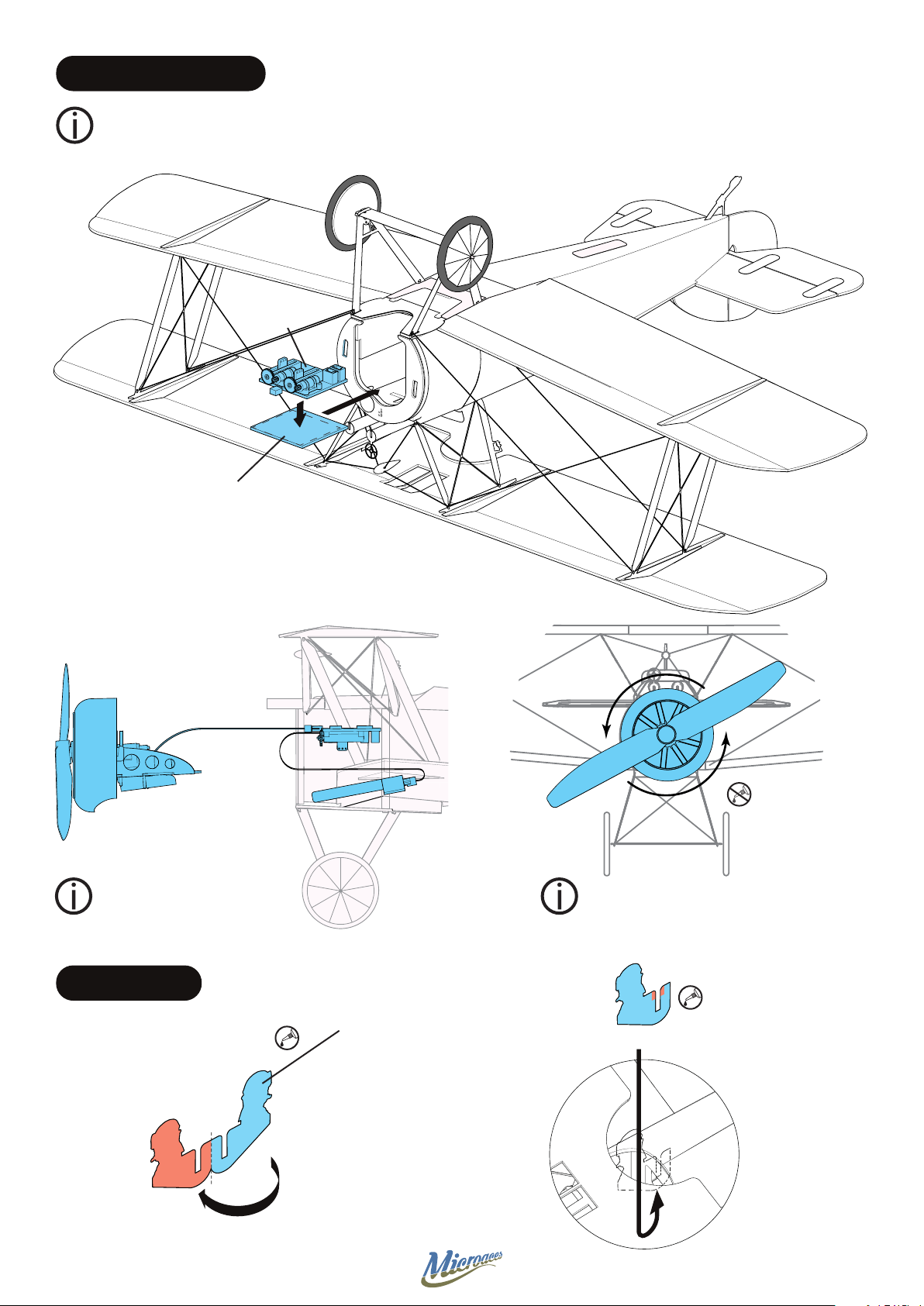
STAGE 18 ELECTRONICS
Ensure receiver servos are centered before installing.
To do this, bind to transmitter and center trims on
Elevator, Ailerons & Rudder (on transmitter).
AIO Receiver
Double Sided
Adhesive Pad
Brick
Correct position of battery Attach motor assembly by
inserting lugs into slots and
rotating until magnets align
STAGE 19 PILOT
Pilot
33
Page 34
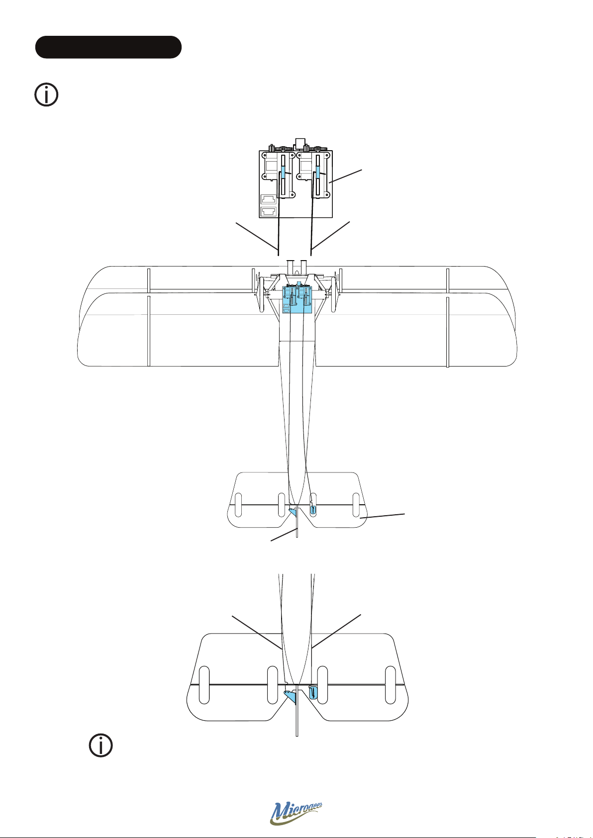
STAGE 20 CONTROL RODS
Insert individual control wire from the rear and attach to appropriate control horn. Set control surface to
neutral then, using slim or needle nose pliers, bend the end of the control wire at the piont it will need
to attach to the servo arm. Un-hook the control wire from the control horn, pull out of the fuselage and
complete the hook bend for the servo arm. Trim hook to 4mm in length.
Microaces
AIO 5CH
Receiver
Control Wire
(Rudder)
Control Wire
(Elevator)
Elevator
Rudder
View from Below
Control Wire
(Rudder)
Control Wire
(Elevator)
The Control Horns for the rudder and elevator are very exible. Install the control
wires for each and use tweezers to bend the horns to insert the ‘Z’ bend into the
hole.
Use the outer hole of the control horns for more gentle control of your aircraft!
34
Page 35
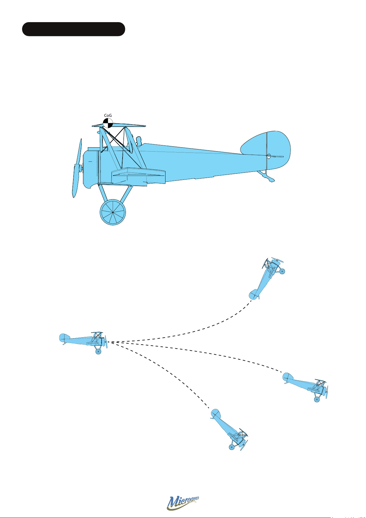
STAGE 21 FINISHING TOUCHES
Centre of Gravity (CoG)
With all the electronics installed including the battery, the CoG should be around the apex of the top wing
as shown on the diagram below.
Balance on nger tips to see if the aircraft balances at this point. Before adding any weight it is advisable to
perform a glide test. Add weight accordingly to obtain a smooth glide.
Glide Test - How to!
Find a suitable test space with a forgiving landing area, e.g. over
long grass or onto soft furnishing. Ensure all control surfaces are
in the neutral position. Gently toss the model straight and level.
Observe the results and add balancing weight if required.
Radio Control Recommendations
The control surfaces are very eective on the Sopwith Camel
Set your transmitter (Tx) control rates to low or if you have a
computerised Tx, set the expo to 50% for both the rudder and the
elevator.
Tail Heavy
Add weight to Nose!
Spot On!
Nose Heavy
Add weight to Tail!
Feel free to adjust these to suit your ying style after the maiden ight!
35
 Loading...