

Micro 8008-04 Installation Instructions Manual

INDEX:
* WIRING INSTRUCTIONS ................................................................ PG 2-7
* LED STATUS INDICATOR ............................................................... PG 8
* SHOCK SENSOR ........................................................................... PG 8
* VALET/OVERRIDE BUTTON ............................................................ PG 9
* EMERGENCY PROTECTION MODE.................................................. PG 9
* PROGRAMMABLE JUMPER-PINS................................................... PG 10
* CODE-LEARNING & PROGRAMMING SECTIONS............................. PG 10-13
* ANTI HI-JACK................................................................................ PG 14
* DOOR LOCKING SECTION.............................................................. PG 15-20
* QUICK REFERENCE GUIDE ............................................................ PG 21
* WIRING DIAGRAM.......................................................................... PG 24
Under the conditions of this warranty, M.A.S. will repair the control module if found to have a defect
in material or factory workmanship for the lifetime of the car in which it is originally installed. All
other components have a one year warranty from the date of purchase. The installation must be performed by an authorized M.A.S. dealer for this warranty to be valid. This warranty is offered to the
original purchase and is not transferrable. This warranty will be void if the product has been abused,
altered, improperly installed or subjected to any other factor that is beyond the manufacturer’s control. This warranty does not cover labor costs for removal or re-installation nor replacement costs of
consumable items such as batteries, fuses, etc.
®
#8008-04
INSTALLATION INSTRUCTIONS
This Is An Anti Code-Grabbing System. The Remote
Control Changes The Code It Transmits Every Time It
Operates The Alarm. If A Used Or Duplicate Code Is
Received The Alarm Will Automatically Trigger.
ANTI CODE-GRABBING PROTECTION
8008_inst.7/7/04.qx
P. 2
8008_inst.7/7/04.qx
WIRING INSTRUCTIONS
MAIN HARNESS
RED: MAIN POWER CONNECTION.
• Connect To The (+)12 Volt Positive Battery Terminal, Fused At 15 AMPS.
WHITE: PARKING LIGHT OUTPUT: (2 INDEPENDENT WIRES)
There Are 2 Independent White Wires, This Is For European Vehicles In Which The Left & Right Side Parking Lights Are
On Different Circuits. If Working On A Standard Vehicle It Is Not Necessary To Hook-Up Both Wires, One Is Sufficient.
• Connect This Wire To The Vehicle’s (+)12 Volt Positive Parking Light Circuit.
• This Output Will Provide A Flashing (+)12 Volt Positive Signal To Flash The Vehicle’s Parking Lights.
• The Vehicle’s Parking Light Wire Will Show (+)12 Volts Positive ONLY When The Light Switch Is Turned To The
“PARKING LIGHT” And “HEADLIGHT” Positions.
• The Vehicle’s Parking Light Wire Can Usually Be Found At The Light Switch, Fuse Junction Block, Or In The
Harness Which Runs To The Rear Of The Vehicle (Usually Found In The Driver’s Side Kick-Panel).
NOTE: DO NOT Connect The White Wire(s) To The Dimmer Switch. This Could Cause Damage To The Vehicle’s Circuit.
NOTE: DO NOT Connect The Alarm’s Flashing Light Wire(s) Directly To Flash The Vehicle’s Headlights. The Headlight
Circuit Is A Very High Amperage Circuit And Will Draw More Than The 7.5 Amp Maximum Load The Alarm’s
On-Board Relay Can Provide. If Flashing Headlights Are Desired, An External Relay Is Required.
(Warning: Halogen Lights Are Not Designed For Flashing Applications And May Therefore Burn Out Quickly).
BROWN: (+)SIREN OUTPUT
This Wire Will Provide A (+)12 Volt Output For Powering A Siren.
•
CONNECT Alarm Brown Wire To Siren’s Red Wire
•
CONNECT Siren’s Black Wire To Ground
WARNING: Do Not Ground The Alarm’s Brown Wire Or Severe Damage Will Occur To The Unit.
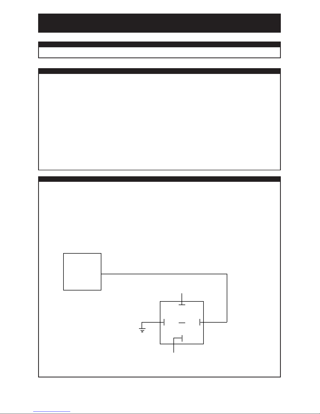
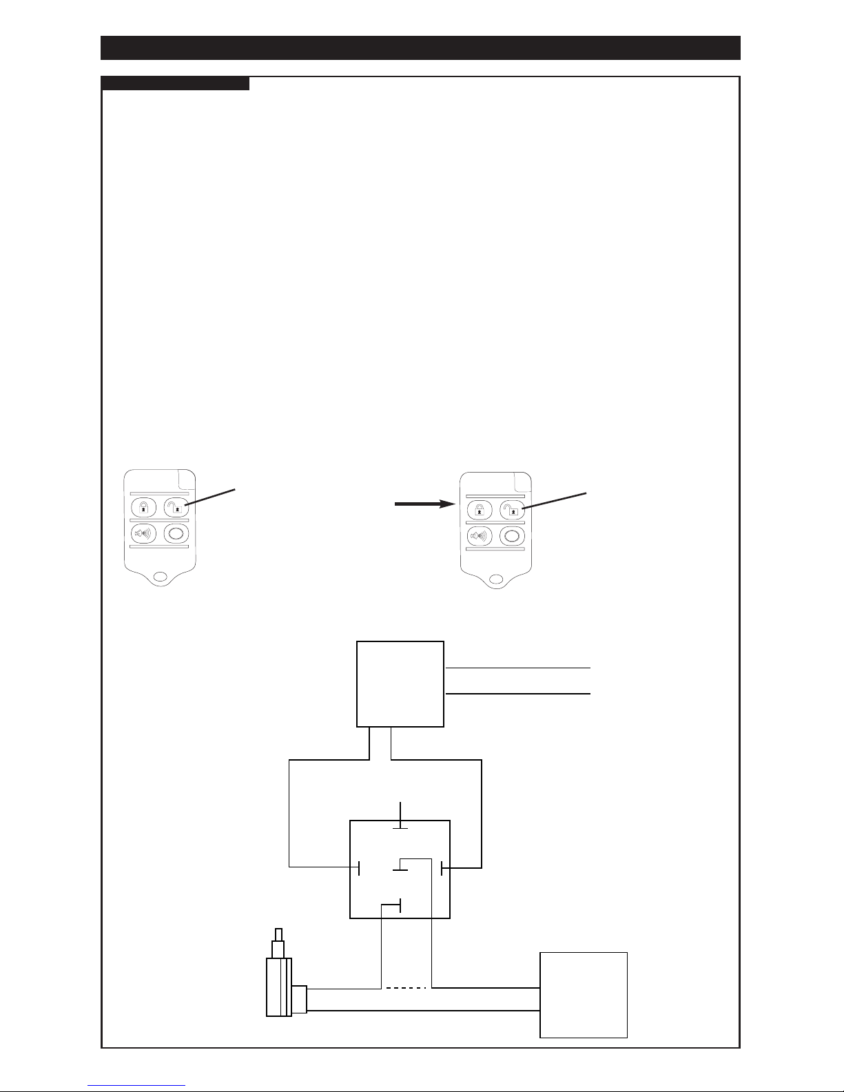
NOTE: If More Than One Siren Is Desired Or If A High-Current Sounding Device Is To Be Used (ie: Mechanical Siren,
Air Horns, Etc) A Relay Will Be Necessary. (SEE DIAGRAM)
ALARM
BROWN (+)
87
87A
85
GROUND
86
30
TO SOUNDING DEVICE (HORN, SIREN, ETC)
CONSTANT 12 VOLTS
FUSED
(+)
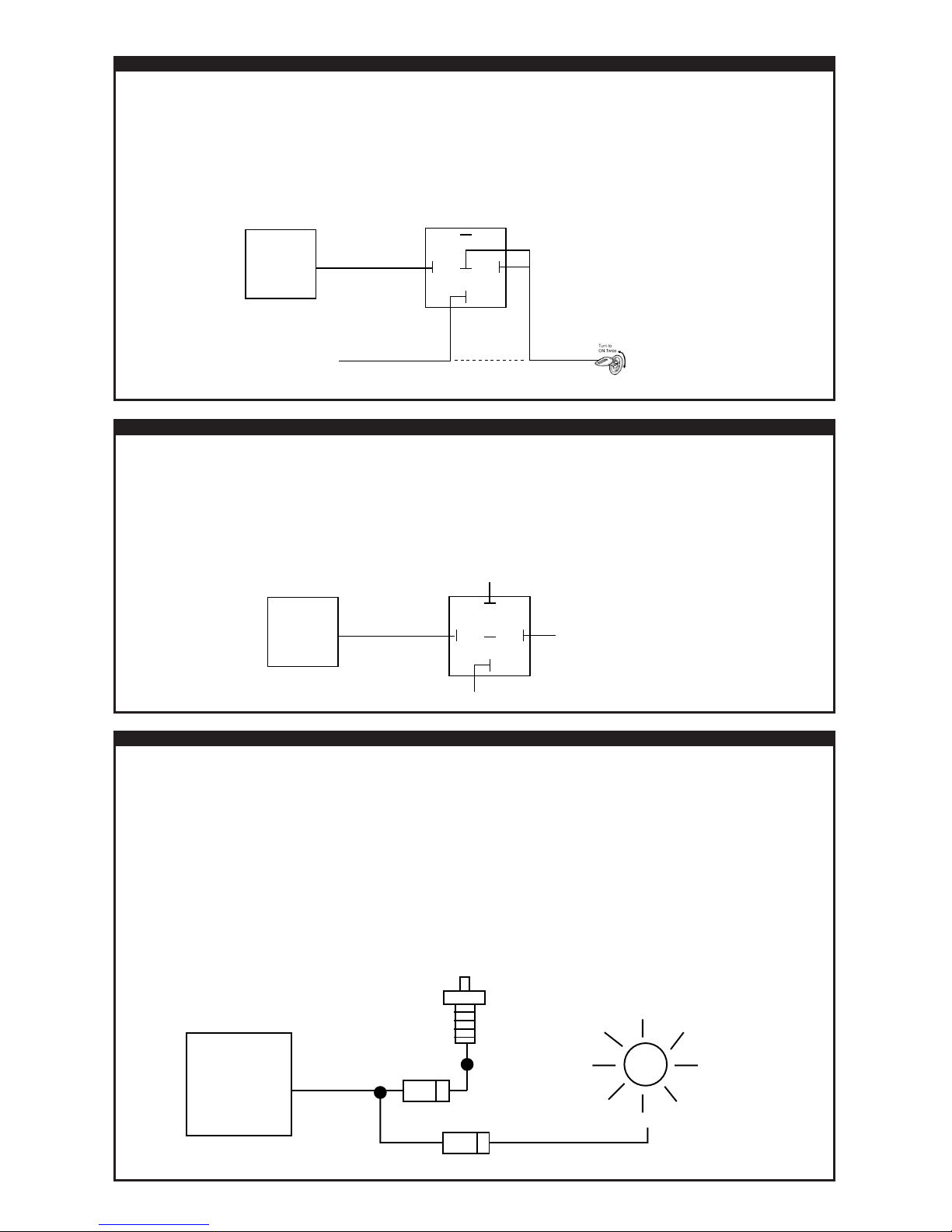
ORANGE: ARMED OUTPUT (FOR STARTER-KILL RELAY)
This Output Will Provide A (-) Negative Signal ONLY When The Alarm Is Armed. This Output Can Be Used To Supply
Ground To One Side Of a Starter-Kill Relay’s Coil. The Other Side Of This Relay’s Coil Will Require A (+) 12 Volt Signal
Supplied By The Ignition Switch (ONLY When The Ignition Is Turned On Or When The Starter Motor Is Cranking). In This
Manner There Will ONLY Be A Current Draw If There Is A Start Attempt While The Alarm Is Armed.
It Will Be Necessary To Locate And Cut The Vehicle’s Starter Motor Wire:
• This Wire Will Show (+) 12 Volts ONLY When The Vehicle’s Starter Motor Is Actually “CRANKING”, If The
Starter Motor Is Not Cranking This Wire Will Usually Rest At Ground. (SEE DIAGRAM)
BLUE: HOOD/TRUNK (-)INSTANT TRIGGER INPUT
The Hood/Trunk (-) Input Is An Instant Trigger Zone.
• This (-) Input will Trigger The Alarm If it Becomes Grounded While The Alarm Is Armed.
• If This (-) Input Is Grounded At The Time The Alarm Is Armed, The Unit Will By-Pass This Particular Zone Until It
Becomes Ungrounded.
• If This (-) Input Is Grounded Before The Alarm Is Armed, The Unit Will NOT Passively Arm (Self-Arm) Until The Input
Is Ungrounded. (The Hood/Trunk Is Closed)
CONNECT The Alarm’s Blue Wire To An Aftermarket or Factory (-) Pin-Switch/Mercury Switch or A (-) Trunk Light
Circuit Which Shows Ground ONLY When The Vehicle’s Hood Or Trunk Is Open.
NOTE: It Is Necessary To DIODE ISOLATE All Circuits And/Or Devices If Connecting The Alarm’s Blue (-) Input Wire
To More Than One Circuit Or Device. (SEE DIAGRAM)
P3
8008_inst.7/7/04.qx
ALARM
BLUE (-) INPUT
HOOD
(-) PIN SWITCH
TRUNK LIGHT
DIODE
(+)
DIODE
STARTER MOTOR WIRE
ALARM
ORANGE (-)
MOTOR
SIDE
87
87A
85 86
30
CUT
KEY SIDE OF
STARTER WIRE
BLACK/WHITE: (-) DOME-LIGHT ILLUMINATION OUTPUT: (Relay Required)
The Alarm’s Black/White Wire Will Provide A 30-Second (-) Negative Output For Illuminating The Vehicle’s Dome-Light
When The Alarm Is Disarmed. (A Relay Is Required) (SEE DIAGRAM)
• This Output Will Reset If The Alarm Is Armed/Disarmed Or If The Vehicle’s Ignition Is Turned On.
WARNING: Do Not Connect The Alarm’s Black/White Wire Directly To The Dome-Light Circuit Or Severe Damage Will
Occur To The Unit.
ALARM
BLACK/WHITE (-)
87
87A
85 86
30
TO DOME LIGHT
(+) OR (-) DEPENDS ON DOME LIGHT CIRCUIT TYPE
CONSTANT (+) 12 VOLTS
FUSE AT 3.5AMPS
(+)
P4
8008_inst.7/7/04.qx
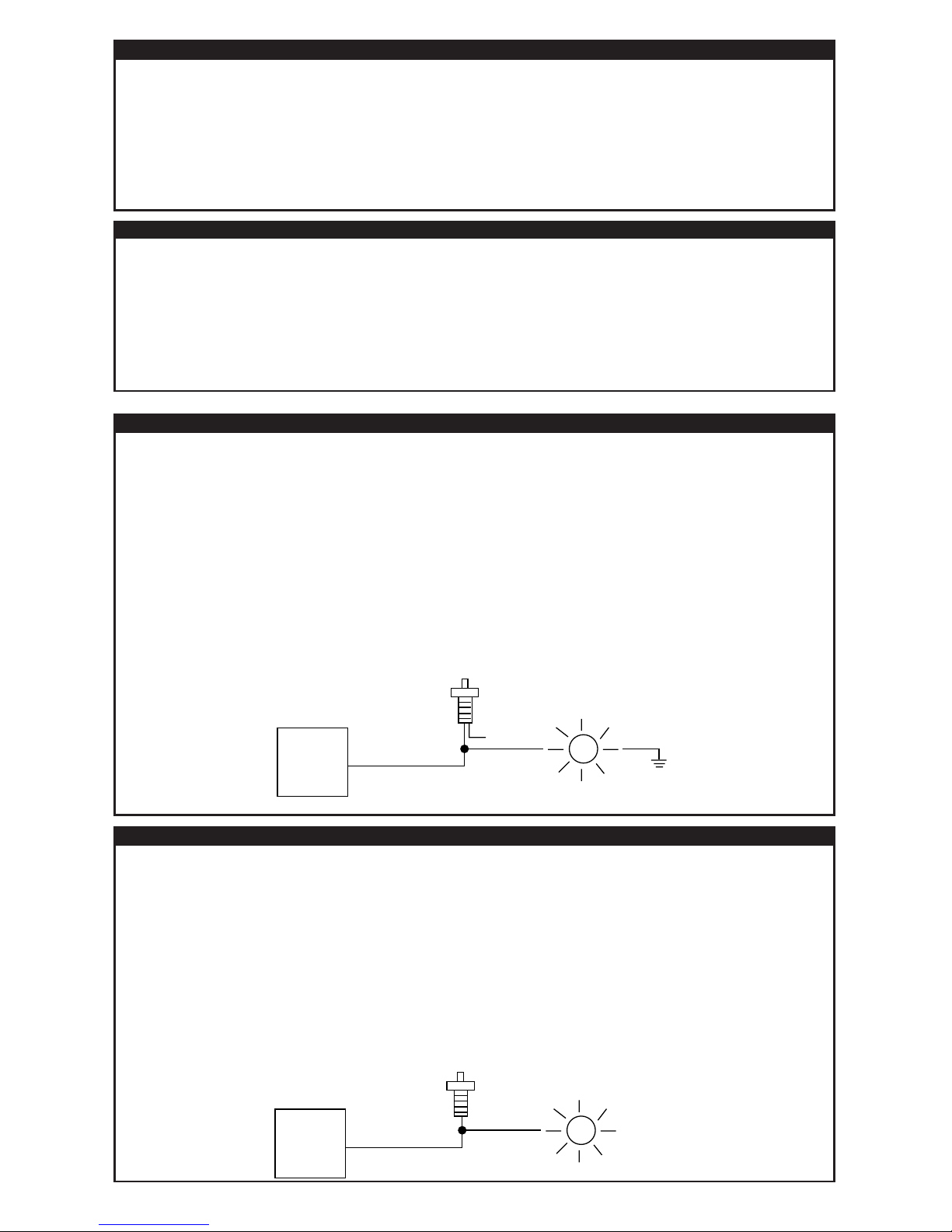
VIOLET: (+) POSITIVE TRIGGER DOOR INPUT
The (+) Door Input Is An Instant Trigger Zone For Vehicles Equipped With A (+) Positive Type Pin-Switch/Dome-Light Circuit.
• This (+) Input Will Trigger The Alarm If It Receives (+) 12 Volts While The Alarm Is Armed. (ie: A Door Is Opened)
• If This (+) Input Is Receiving (+) 12 Volts At The Time The Alarm Is Armed, The Unit Will By-Pass This Particular
Zone Until It Is Removed From (+) 12 Volts.
• If This (+) Input Is Receiving (+) 12 Volts Before The Alarm Is Armed, The Unit Will NOT Passively Arm (Self-Arm)
Until The Input Is Removed From (+) 12 Volts (The Doors Are Closed).
INSTALLATION NOTE: This Trigger Input Can Be Programmed For A 60 Second Delay Option Designed For Vehicles
With Extended Dome-Light Delays. (See Programmable Jumper-Pin Options: #4)
CONNECT The Alarm’s Violet Wire To The (+) 12 Volt Factory OEM Pin-Switch/Dome-Light Circuit. This
Circuit Will Show (+) 12 Volts ONLY When A Vehicle Door Is Open. (SEE DIAGRAM)
NOTE: It Is Necessary To Confirm That All Vehicle Doors Are Included In The Circuit.
GREEN: (-)NEGATIVE TRIGGER DOOR INPUT
The (-) Door Input Is An Instant Trigger Zone For Vehicles Equipped With A (-) Negative Type Pin-Switch/Dome-Light Circuit.
• This (-) Input Will Trigger The Alarm If It Becomes Grounded While The Alarm Is Armed. (ie: A Door Is Opened)
• If This (-) Input Is Grounded At The Time The Alarm Is Armed, The Unit Will By-Pass This Particular Zone Until It
Becomes Ungrounded.
• If This (-) Input Is Grounded Before The Alarm Is Armed, The Unit Will NOT Passively Arm (Self-Arm) Until The Input
Is Ungrounded (The Doors Are Closed).
INSTALLATION NOTE: This Trigger Input Can Be Programmed For A 60 Second Delay Option Designed For Vehicles
With Extended Dome-Light Delays. (See Programmable Jumper-Pin Options:#4)
CONNECT The Green Wire To The (-) Negative Factory OEM Pin-Switch/Dome-Light Circuit. This Circuit Will Show
(-) Negative Ground ONLY When A Vehicle Door Is Open.(SEE DIAGRAM)
NOTE: It Is Necessary To Confirm That All Vehicle Doors Are Included In The Circuit.
ALARM
GREEN (-) INPUT
VEHICLE DOOR
(-) PIN SWITCH
DOME LIGHT
(+)
ALARM
VIOLET (+) INPUT
VEHICLE DOOR
(+) PIN SWITCH
DOME LIGHT
(+)
YELLOW: PRIMARY IGNITION POWER
This Input Will Provide The Alarm With A (+) 12 Volt Signal When The Vehicle Engine Is Running, Or
When The Ignition Is Turned “ON”. This Connection Is Necessary For Many Vital Functions Such As Passive/Active
Arming, Valet Mode, Override, Programming, LED & Memory Reset, Auto-Lock, Etc.
•
CONNECT To The Vehicle’s (+) 12 Volt Primary Ignition Wire.
• The Vehicle’s Primary Ignition Wire Will Show (+) 12 Volts When The Ignition Key Is Turned To The
ON & START Positions.
• This Wire Will NOT Drop Out During Starter Motor Cranking.
• This Wire Will NOT Show (+) 12 When The Vehicle’s Ignition Key Is Turned OFF.
BLACK: GROUND
• CONNECT This Wire To Chassis Ground.
• It Is Of Upmost Importance That The Location Of This Connection Be As Clean As Possible. Make Sure That The
Area Is Rust And Grease Free. Scrape Off Any Paint Or Debris So That The Surface Is Bright Clean Metal.
• If The Ground Connection Is Poor, The Alarm May Act In An Erratic Manner. The Alarm May Arm And Disarm
Correctly, But Would Otherwise Behave Very Strangely Making It Seem That The Unit Is Defective. One Possible
Symptom Is A Constant Low Volume Sound Coming From The Siren
NOTE: DO NOT Ground The Thin Black Wire Attached To The Brain Module, This Is The Unit’s ANTENNA.
Connecting This To Anything Would Severely Affect The Unit’s Range.
P. 5
8008_inst.7/7/04.qx
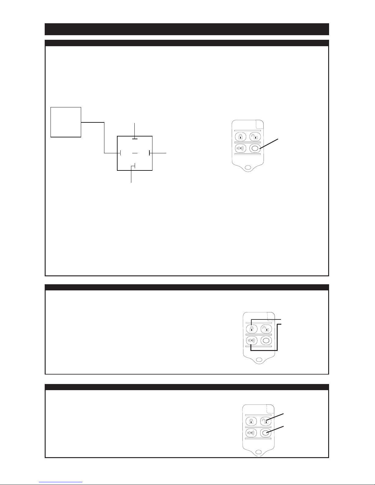
AUXILIARY OUTPUT PLUG
GREY: AUXILIARY OUTPUT CHANNEL #1: (PROGRAMMABLE)
This Programmable Auxiliary Channel Will Provide A Momentary (-) Negative Output When The “AUX” Button On The
Remote Control Is Pressed Momentarily. (See Programming Section: Vector #4)
This Auxiliary Output Has 2 Programmable Settings:
1) TRUNK/HATCH RELEASE WITH DISARM. (DEFAULT)
• This Setting Will Automatically Disarm The Alarm & Provide A Momentary (-) Pulse For A Trunk/Hatch Release.
(SEE DIAGRAM)
2) HIGH SECURITY CAR-START INTERFACE: (MUST BE PROGRAMMED)
• This Programmable Setting Is Designed To Activate A Car-Start Module Without Having To Disarm The Alarm,
Maintaining High Security While The Vehicle Is Running.
• This Setting Will Provide A Momentary (-) Pulse To Activate A Car-Start Module And Automatically By-Pass
The Sensor Zone When The Ignition Turns “ON” To Prevent False Alarms. (No Sensor By-Pass Relay Necessary).
The Door/Hood/Trunk Zones Remain Fully Armed.
• If The Alarm Is Triggered While The Vehicle Is Running, A Pulse Will Be Sent To The Car-Start Module To Turn
The Vehicle “OFF”.
CONNECT To A Car-Start Module’s (-) Activation Input Wire.
GREY/WHITE: AUXILIARY OUTPUT CHANNEL #2: (PROGRAMMABLE)
This Programmable Auxiliary Channel Will Provide A CONSTANT or LATCHED (-) Negative Output When Buttons “LOCK
& PANIC” On The Remote Control, Are Pressed Momentarily. (See Programming Section: Setting #4)
This Auxiliary Output Has 2 Programmable Settings:
1) CONSTANT OUTPUT: (DEFAULT)
• This Setting Will Provide A Constant (-) Negative Output. As Long As
The Buttons are Held Down.
2) LATCHED 30 SECOND OUTPUT: (MUST BE PROGRAMMED)
• This Setting Will Provide A (-) Negative Latched Output For 30 Seconds.
• This Latched Output Will Reset Anytime The Remote Control Is Used.
GREY/BLACK: AUXILIARY OUTPUT CHANNEL #3:
This Auxiliary Channel Will Provide A Constant (-) Negative Output When Buttons “UNLOCK & AUX” Are Pressed & Held
For 2 Seconds.This Output Will Remain Constant As Long As The Buttons Are Held
ALARM
GREY(-)
VEHICLE’S TRUNK/HATCH
RELEASE WIRE
DEPENDING ON
PARTICULAR APPLICATION
(+) or (-)
87
87A
85 86
30
CONSTANT (+) 12 VOLTS
USE 3.5 AMP FUSE
(+)
AUX
PRESS & RELEASE
THE “AUX” BUTTON
TO ACTIVATE
CHANNEL #1
AUX
PRESS & RELEASE
BUTTONS “LOCK
& PANIC”
SIMUTANEOUSLY
TO ACTIVATE
CHANNEL #2
AUX
PRESS & HOLD
BUTTONS
“UNLOCK & AUX”
FOR 2 SECONDS
TO ACTIVATE
CHANNEL #3
AUX
AUX
PRESS & RELEASE
“UNLOCK” BUTTON
TO DISARM ALARM
& UNLOCK ONLY THE
DRIVER’S DOOR
PRESS & RELEASE
THE “UNLOCK” BUTTON
WITHIN 3 SECONDS OF
DISARMING THE ALARM TO
UNLOCK THE REMAINING
DOORS
THEN
P. 6
8008_inst.7/7/04.qx
DOOR LOCK/UNLOCK PLUG:
DRIVER’S DOOR UNLOCK: This Alarm Is Equipped With A 2-Stage Unlock Process Which Allows The User to Unlock
ONLY The Driver’s Door When Disarming The Alarm. Rest Of The Doors Can Be Unlocked By Pressing The “UNLOCK”
Button A Second Time Within 3 Seconds Of Disarming The Alarm. If This Feature Is Desired, Then 2 Independent Alarm
Unlock Wires Must Be Used.
If “UNLOCK” Is Pressed One Time To Disarm The Alarm, The Pink Wire Will Provide A
(-) Unlock Pulse & The Green Wire Will Provide A (+) Unlock Pulse. If “UNLOCK” Button Is Pressed Again Within 3Seconds Of Disarm The Blue Wire Will Provide A (-) Unlock Pulse.
NOTE: It Is NOT Necessary To Wire The Driver’s Door Unlock Feature. If The Feature Is Not Desired Do Not Connect The
Blue 2nd Unlock Wire. Only Connect The Primary Lock & Unlock Wires. (Green & Pink)
NOTE: If Door Locks Are Activated By Locking And Unlocking The Doors (Central Locking System). Driver’s Door
Unlock Will Not Be Possible.
When Arming The Alarm:
• The Green Wire Will Provide A (-) Lock Pulse.
• The Pink Wire Will Provide A (+) Lock Pulse.
When Disarming The Alarm:
• The Pink Wire Will Provide A (-) Unlock Pulse.
• The Green Wire Will Provide A (+) Unlock Pulse.
Second Press Of “UNLOCK” Button Within 3-Seconds Of Disarm:
• The Blue Wire Will Give A (-) Unlock Pulse.
(SEE DIAGRAM)
ALARM
GREEN (-) OR PINK (+) LOCK
87
CUT
UNLOCK WIRE
LOCK WIRE
SWITCH SIDE
OF UNLOCK
WIRE
DRIVER'S SIDE
OF UNLOCK
WIRE
DRIVER'S SIDE
DOOR LOCK
MOTOR
87A
85 86
30
BLUE (-) UNLOCK
PINK(-) OR
GREEN (+)
UNLOCK
RED (+)
CONSTANT
CONSTANT (+) 12 VOLTS
FUSE AT 5 AMPS
(+)
TO ALL
DOORS
SWITCH
DRIVER’S DOOR UNLOCK HOOK-UP

P. 7
GREEN: DOOR (-)LOCK / (+)UNLOCK OUTPUT:
The Alarm’s Green Lock/Unlock Wire Is A Flip-Flop Type Of Circuit. It Will Provide A (-) Lock Pulse & A (+) Unlock Pulse.
The Hook-Up & Interface Necessary Will Depend On The Type Of Door Locking System The Vehicle Is Equipped With.
Please Refer To The Door-Locking Section In This Manual.
•A (-) Negative LOCK Pulse Will Be Provided When ARMING The Alarm.
•A (+) Positive UNLOCK Pulse Will Be Provided When DISARMING The Alarm.
PROGRAMMING NOTE: The Green Wire Can Be Programmed To Provide A Double (-) Lock Pulse Or A Double (+)
Unlock Pulse. This Is Necessary In Some VW’s. (See Programming Section: Feature
Setting #1)
PROGRAMMING NOTE: This Wire Can Be Programmed To Give A 1 Or 3 Second Pulse.
(SEE PROGRAMMABLE JUMPER OPTIONS).
RED: CONSTANT (+)12 VOLTS POSITIVE:
This Red Wire Will Provide Constant (+)12 Volts For Powering Only The Coils On External Relays If Necessary.
NOTE: DO NOT Use The Red Wire To Power Any Other Device (ie: Aftermarket Actuators) Or Severe Damage Will
Occur To The Unit.
PINK: DOOR (-) UNLOCK / (+) LOCK OUTPUT:
The Alarm’s Pink Lock/Unlock Wire Is A Flip-Flop Type Of Circuit. It Will Provide A (-) Unlock & A (+) Lock Pulse.
The Hook-Up & Interface Necessary Will Depend On The Type Of Door Locking System The Vehicle Is Equipped With.
Please Refer To The Door-Locking Section In This Manual.
•A (-) Negative UNLOCK Pulse Will Be Provided When DISARMING The Alarm.
•A (+) Positive LOCK Pulse Will Be Provided When ARMING The Alarm.
PROGRAMMING NOTE: The Pink Wire Can Be Programmed To Provide A Double (-) Unlock Pulse. This Is
Necessary In 1995+ Nissan Maximas.
(See Programming Section: Feature Setting #1)
PROGRAMMING NOTE: This Wire Can Be Programmed To Give A 1 Or 3 Second Pulse.
(SEE PROGRAMMABLE JUMPER OPTIONS).
BLUE: 2ND UNLOCK WIRE
The Alarm’s Blue Wire Will Provide A (-) Negative Unlock Pulse When The “UNLOCK” Button On The Remote Control Is
Pressed A Second Time Within 3 Seconds Of Disarming The Alarm.
PROGRAMMING NOTE: The Blue Unlock Can Be Programmed To Provide A Double (-) Unlock Pulse. This Is
Necessary In 1995+ Nissan Maximas. The Double (-) Pulse Can Be Converted To A Double
(+) Pulse Using A Relay For Use In Some VW’s Which Require A Double (+) Pulse To Unlock
The Doors. (See Programming Section: Feature Setting #2)
PROGRAMMING NOTE: This Wire Can Be Programmed To Give A 1 Or 3 Second Pulse.
(SEE PROGRAMMABLE JUMPER OPTIONS).
8008_inst.7/7/04.qx
P. 8
8008_inst.7/7/04.qx
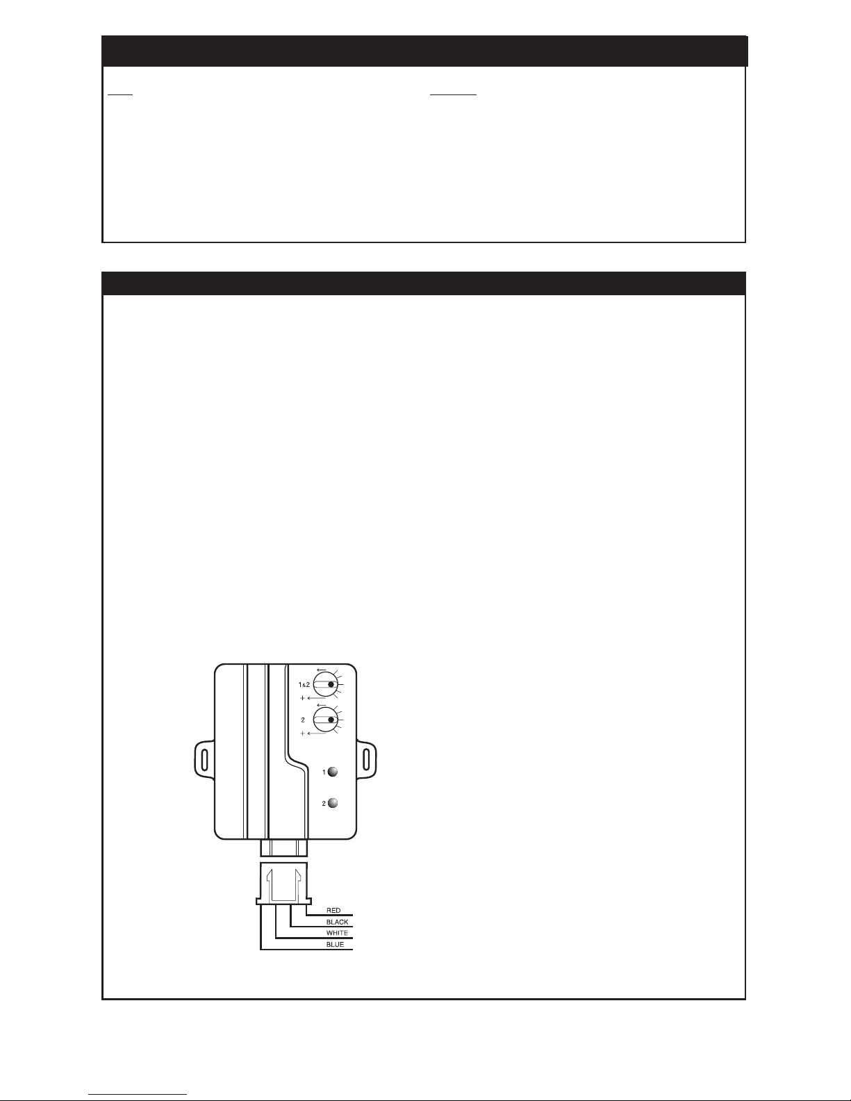
(BLACK NUT)
Adjusts both stage 1 and stage 2
(GRAY NUT)
Adjusts stage 2 only
(GREEN)
1st stage indicator
(RED)
2nd stage indicator
+ 12vDC
(-) armed output (grounded only when the alarm is armed)
Warning zone
Instant trigger zone
LED: STATUS INDICATOR
LED: STATUS:
Off Alarm Disarmed
Flashing Slowly Alarm Armed
Flashing Rapidly (Alarm Disarmed) Self-Arm Countdown
Flashing Rapidly (Alarm Armed) Intrusion Confirmation
Flashing Rapidly (Ignition “ON”) Anti Hi-Jack Countdown
On Solid Valet Mode
CONNECTION: Mount Where Desired And Plug It In.
DUAL-STAGE SHOCK SENSOR: (DUAL-ADJUSTMENT)
This alarm system comes equipped with a dual-stage shock sensor. The first stage is a warning zone which if triggered will emit a series of siren chirps. The second stage is an instant trigger zone. Each zone can be independantly
adjusted for appropriate sensitivity.
ADJUSTMENT: When adjusting this sensor, it is recommended to set the screw at the half rotation first, then
adjust the sensitivity of the “pre-warn” circuit followed by the adjustment of the instant trigger zone.
NOTE: If the sensor zone is triggered 5 times while the alarm is armed, the sensor zone will be bypassed. This
zone will reset when disarming the alarm.
MOUNTING: Correct Placement Is Essential For Proper Operation. The Sensor Should Be Mounted To A Rigid Wire
Harness Under The Dash Using Plastic Cable-Ties Or Directly To The Firewall Using Double Sided Tape. Do Not Mount
With Screws And Do Not Place Under The Hood, This Unit Is Designed For Interior Use Only.
CONNECTION: Plug It In.
Red Wire: Constant (+)12 Volts
Black wire: (-) armed output (grounded only when the alarm is armed)
White Wire: Warning Zone
Blue Wire: Instant Trigger Zone
 Loading...