

Page 1
Warranty void if not installed by authorized dealer.
Specification and date are subject to change or withdrawal without notice.
© 2011 Micro Alarm, Inc. • 6888-Inst-oct2011.indd
REPLACEMENT REMOTE PART NUMBER: #REMOTE-6888
INSTALLATION MANuAL
#6888
THIS IS ONLY A GUIDE
These instructions are a general guideline of possible applications. Specifications may change dependent
upon vehicle. A lways review the vehicle’s service ma nual and wiring diagram when performing an
installation. M anufacturer does not assume a ny responsibility for damages to property or persons
which may occur due to incorrect application s or product failure. Not responsi ble for typographical
errors. Specifications are subject to change without notice.
8
6. ANTI HI-JACK MODE
There are three different ways to activate Anti Hi-Jack (AHJ).
1. By Ignition (Programmable Feature #7, Default setting is OFF)
When Programmable Feature #7 is ON, and the ignition is turned
on, the alarm will enter AHJ mode. The siren will chirp three times
and the LED will flash fast.
Note: If programmable feature #7 hi-jack through ignition is enabled
(ON) you must exit hi-jack mode using the valet button before
entering programming mode, see section 4 to enter programming
mode. Do not turn ignition off, leave ignition on, then press valet
button 5 times to enter programming mode.
2. By Door (Programmable Feature #8, Default setting is OFF)
When Programmable Feature #8 is ON, and when the Ignition is ON
AND the driver door is opened then closed, alarm will enter AHJ
mode. The siren will chirp three times and the LED will flash fast.
3. By Remote Control (Programmable Feature #9, Default setting is OFF)
When Programmable Feature #9 is ON and Ignition ON, Press and
hold PANIC and AUX together for 2 seconds – alarm will enter AHJ
mode. Siren will chirp three times and LED will flash fast.
NOTE: All three features can be set to ON.
ANTI HI-JACK MODE ACTIVATED STATUS
• From 0-60 sec LED will flash quickly.
• From 61-70 sec LED will flash quickly, siren chirps, and the
parking light will flash.
• From 71-80 sec LED will flash quickly, siren chirps, parking light
will flash, and ignition cut output constantly.
• After 81 sec LED will flash quickly, siren chirps, parking light will
flash and ignition cut output constantly.
EXIT ANTI HI-JACK MODE
• From 00-60 sec, Turn on the ignition, then press and hold UNLOCK
button for 2 sec. The system will be in disarm mode.
• After 60 sec, Turn on ignition, then press override switch for 1 sec.
The system will be in disarm mode.
#6888
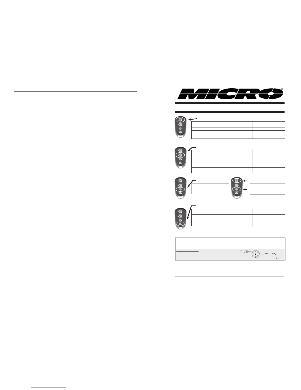
REMOTE OPERATION GUIDE
LOCK BUTTON
• Press and release the LOCK button to ARM ALARM
and LOCK DOORS
Ignition must be OFF
• Press and release the LOCK button to LOCK DOORS During Valet Mode
• Press and release LOCK button and press it again for
2 SECONDS to BYBASS SHOCK SENSOR and ARM
ALARM (Use this to bypass shock sensor)
Ignition must be OFF
#6888
REMOTE OPERATION GUIDE
LOCK BUTTON
UNLOCK BUTTON
• Press and release the LOCK button to ARM ALARM
and LOCK DOORS
Ignition must be OFF
• Press and release the LOCK button to LOCK DOORS During Valet Mode
• Press and release LOCK button and press it again for
2 SECONDS to BYBASS SHOCK SENSOR and ARM
ALARM (Use this to bypass shock sensor)
Ignition must be OFF
• Press and release the UNLOCK button to DISARM
ALARM and UNLOCK DOORS
Alarm must be ARMED and
Ignition OFF
• Press and release the UNLOCK button to STOP
ALARM TRIGGER
W
hen siren / horn is Sounding
• Press and release the UNLOCK button to UNLOCK
DOOR
During Driving or Valet Mode
• Press and Hold the UNLOCK button for 2 SECONDS
to switch ALARM to KEYLESS basic mode.
Alarm must be DISARMED
and Ignition ON.
#6888
REMOTE OPERATION GUIDE
LOCK BUTTON
UNLOCK BUTTON
PANIC BUTTON
• Press and release the LOCK button to ARM ALARM
and LOCK DOORS
Ignition must be OFF
• Press and release the LOCK button to LOCK DOORS During Valet Mode
• Press and release LOCK button and press it again for
2 SECONDS to BYBASS SHOCK SENSOR and ARM
ALARM (Use this to bypass shock sensor)
Ignition must be OFF
• Press and release the UNLOCK button to DISARM
ALARM and UNLOCK DOORS
Alarm must be ARMED and
Ignition OFF
• Press and release the UNLOCK button to STOP
ALARM TRIGGER
W
hen siren / horn is Sounding
• Press and release the UNLOCK button to UNLOCK
DOOR
During Driving or Valet Mode
• Press and Hold the UNLOCK button for 2 SECONDS
to switch ALARM to KEYLESS basic mode.
Alarm must be DISARMED
and Ignition ON.
• Press and hold the PANIC button for 2 SECONDS to TRIGGER
HORN / SIREN
• Press LOCK and PANIC buttons
together to get AUX2 Output.
Note: Contact installer to make sure this
option is enabled.
LOCK
PANIC
PRESS
TOGETHER
2nd AUXILIARY
#6888
REMOTE OPERATION GUIDE
LOCK BUTTON
UNLOCK BUTTON
PANIC BUTTON
AUX BUTTON
• Press and release the LOCK button to ARM ALARM
and LOCK DOORS
Ignition must be OFF
• Press and release the LOCK button to LOCK DOORS During Valet Mode
• Press and release LOCK button and press it again for
2 SECONDS to BYBASS SHOCK SENSOR and ARM
ALARM (Use this to bypass shock sensor)
Ignition must be OFF
• Press and release the UNLOCK button to DISARM
ALARM and UNLOCK DOORS
Alarm must be ARMED and
Ignition OFF
• Press and release the UNLOCK button to STOP
ALARM TRIGGER
W
hen siren / horn is Sounding
• Press and release the UNLOCK button to UNLOCK
DOOR
During Driving or Valet Mode
• Press and Hold the UNLOCK button for 2 SECONDS
to switch ALARM to KEYLESS basic mode.
Alarm must be DISARMED
and Ignition ON.
• Press and release the AUX button for TRUNK
RELEASE
• Press and hold the AUX button for 2 SECONDS for
SILENT ARMING and Lock Doors
Alarm must be DISARMED
and ignition OFF
• Press and hold the AUX button for 2 SECONDS for
SILENT DISARMING and Unlock Doors
Alarm must be ARMED and
ignition OFF
• Press and hold the PANIC but-
ton for 2 SECONDS to TRIGGER
HORN / SIREN
• Press LOCK and PANIC buttons
together to get AUX2 Output.
Note: Contact installer to make sure this
option is enabled.
LOCK
PANIC
PRESS
TOGETHER
2nd AUXILIARY
#6888
REMOTE OPERATION GUIDE
LOCK BUTTON
UNLOCK BUTTON
PANIC BUTTON
AUX BUTTON
• Press and release the LOCK button to ARM ALARM
and LOCK DOORS
Ignition must be OFF
• Press and release the LOCK button to LOCK DOORS During Valet Mode
• Press and release LOCK button and press it again for
2 SECONDS to BYBASS SHOCK SENSOR and ARM
ALARM (Use this to bypass shock sensor)
Ignition must be OFF
• Press and release the UNLOCK button to DISARM
ALARM and UNLOCK DOORS
Alarm must be ARMED and
Ignition OFF
• Press and release the UNLOCK button to STOP
ALARM TRIGGER
W
hen siren / horn is Sounding
• Press and release the UNLOCK button to UNLOCK
DOOR
During Driving or Valet Mode
• Press and Hold the UNLOCK button for 2 SECONDS
to switch ALARM to KEYLESS basic mode.
Alarm must be DISARMED
and Ignition ON.
• Press and release the AUX button for TRUNK
RELEASE
• Press and hold the AUX button for 2 SECONDS for
SILENT ARMING and Lock Doors
Alarm must be DISARMED
and ignition OFF
• Press and hold the AUX button for 2 SECONDS for
SILENT DISARMING and Unlock Doors
Alarm must be ARMED and
ignition OFF
• Press and hold the PANIC but-
ton for 2 SECONDS to TRIGGER
HORN / SIREN
• Press LOCK and PANIC buttons
together to get AUX2 Output.
Note: Contact installer to make sure this
option is enabled.
VALET OVERRIDE SWITCH OPERATION
USED FOR: 1. Stopping horn/siren: Turn ignition on, press and hold valet switch until horn/siren stops.
2. To enter/exit keyless basic mode (LED steady on): Ignition on and hold valet switch for 5 seconds.
3. Use to program remotes: Turn ignition on, press and release valet switch 5 times, press lock buttons on
each remote to be programmed, turn ignition off. Up to 4 remotes may be programmed.
Most Common Locations
(Ask installer where it is located.)
• Inside glove compartment, driver's kick panel, behind the
fuse panel access door, underneath
the dashboard in front of the driver.
LOCK
PANIC
PRESS
TOGETHER
2nd AUXILIARY
Page 2
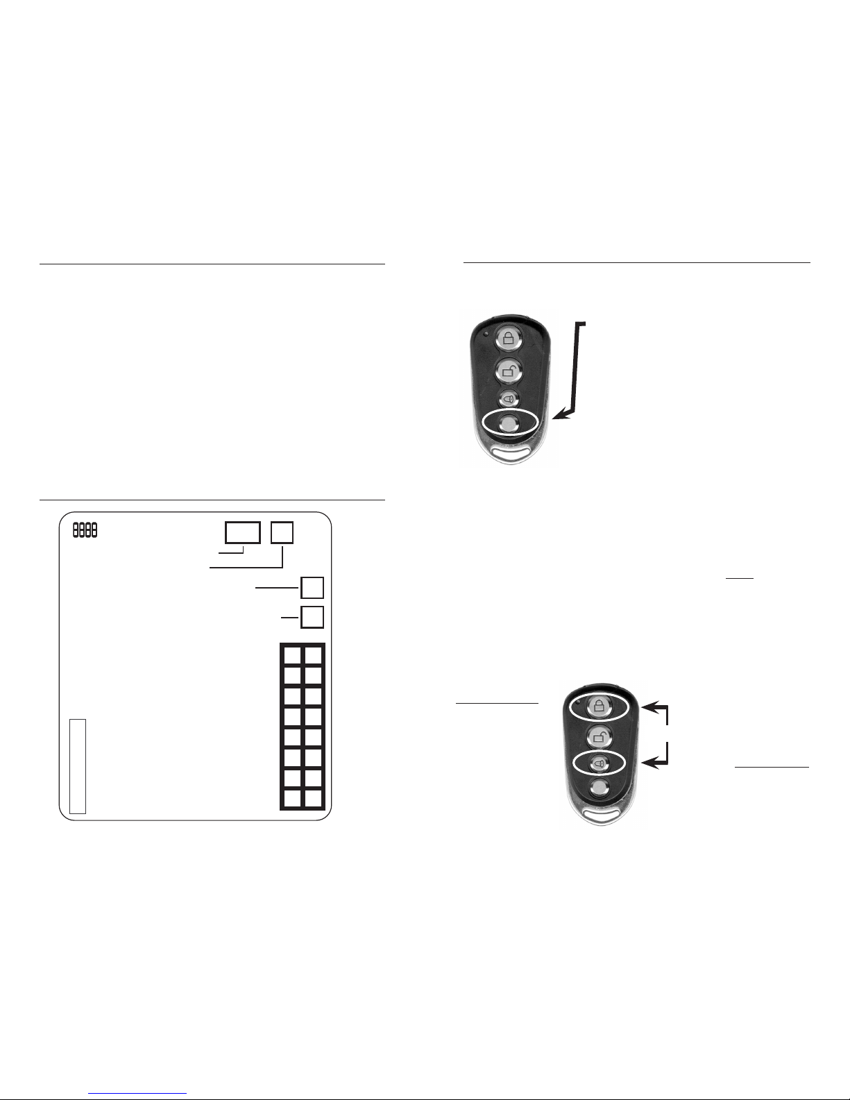
1. HOW TO “CODE LEARN” A REMOTE CONTROL:
When Car Alarm is Disarmed and Ignition is off:
1. Turn Ignition To ON Position.
2. Press Valet Override Switch 5 Times. Siren / Horn will Chirp Once
and Parking Light and LED will stay ON.
3. Press LOCK on each remote to be programmed. Siren / Horn
will chirp and parking light will flash to confirm remote has been
programmed.
4. Turn Ignition OFF.
Note 1: After 10 seconds without any programming activity, or if the
ignition is turned OFF, the System will automatically exit Remote
Control Programming Mode.
Note 2: Up 4 Remote Controls can be programmed.
2. JUMPER PIN AND WIRING CONFIGURATION
6888 BRAINSTICKER
6cm
JP1
JP2
JP3
JP4
REPLACEMENT REMOTE PART#:
REMOTE-6888
16 - N/A
15 - BLACK/WHITE WIRE (–) Dome Light Output
14 - N/A
13 - BROWN/WHITE WIRE (–) 2nd AUX / Horn
12 - BLUE WIRE (–) Hood Pin Input
11 - ORANGE WIRE (–) Starter Disable
10 - PURPLE WIRE (+) Door Trigger Input
9 - N/A
8 - GREEN WIRE (–) Door Trigger Input
7 - GREY WIRE (–) Trunk Release Output (Aux)
6 - YELLOW WIRE (+) Ignition Input
5 - BROWN WIRE (+) Siren Output (3 Amp)
4 - BLACK WIRE (–) Ground
3 - WHITE WIRE (+/–) Parking Light Output
2 - RED WIRE (+) 12 Volts
1 - RED/WHITE WIRE (+/–) Parking Light Input
16
14
12
10
8
6
4
2
15
13
11
9
7
5
3
1
LED (WHITE CONNECTOR)
VALET SWITCH (BLUE CONNECTOR)
DOOR LOCK
(RED CONNECTOR)
SHOCK SENSOR
(WHITE CONNECTOR)
JP1 - OPEN = Last Door Arm/Auto Rearm = OFF
CLOSED = Last Door Arm/Auto Rearm = ON
JP2 -
OPEN = Last Door Arm/Auto Rearm w/o Door Lock
CLOSED = Last Door Arm/Auto Rearm w/ Door Lock
JP3 - OPEN = Door Light Delay for 60 Sec = ON
CLOSED = Door Light Delay for 60 Sec = OFF
JP4 - OPEN = CDL Pulse Timer = 3.5 Sec
CLOSED = CDL Pulse Timer = 0.5 Sec
NOTE: DEFAULT FOR ALL JPS IS CLOSED
#6888
2 7
5. 6888 ADDITIONAL INFORMATION
AUXILIARY ONE (Grey Wire) maybe used for either Trunk Release
(default) or Remote Starter. (Programmable feature #3)
Press and relase AUX button to release
trunk OR engage Remote Starter.
• If Gray Wire is used for Trunk Release:
the system will disarm and unlock
vehicle
• If Gray wire is connected to enable
Remote Starter, the system will bypass
sensor and ignition
• Programmable feature #3 must be
programmed to either Trunk Release
(default) or Remote Starter.
SECOND AUXILIARY or HORN OUTPUT (Brown/White Wire) has
four programmable options (programmable feature #4):
1. PULSE – Provides a negative output as long as “Lock” and “Panic”
are pressed and held together. (Default)
2. LATCH OUTPUT – Provides a negative output for 25 seconds
when “Lock” and “Panic” buttons are pressed together at the
same time and released.
3. HORN – Horn and siren work together only on all alarm events.
Siren will work on all events.
4. LIMITED HORN – Horn enables when alarm is triggered. Horn
does not activate when lock/unlock is pressed on the remote, only
the siren chirps.
NOTE: Programmable feature #4 must be programmed to how the
Brown/White wire is connected and intended to be used. ONLY
ONE OPTION MAY BE SELECTED AND PROGRAMMED.
IF LATCH IS WIRED /
CONFIGURED:
Press and Release
“Lock” and “Panic”
at same time to get a
negative output for 25
seconds
LOCK
PANIC
AUXILIARY 2:
IF PULSE IS WIRED /
CONFIGURED (Default):
A negative output will
be provided by pressing
and holding “Lock” and
“Panic” at the same time.
Output will be provided
as long as “Lock” and
“Panic” are held.
PRESS
TOGETHER
Page 3
2A. JUMPER PIN INFORMATION
Jumper 1
OPEN – Last Door Arm/Auto Rearm = OFF
CLOSE – Last Door Arm/Auto Rearm = ON
Jumper 2
OPEN – Last Door Arm/Auto Rearm without Door Lock
CLOSE – Last Door Arm/Auto Rearm with Door Lock
Jumper 3
OPEN – Dome Light Delay for 60sec = ON
CLOSE – Dome Light Delay for 60sec = OFF
Jumper 4
OPEN – Central Door Lock (CDL) Pulse Timer = 3.5sec
CLOSE – Central Door Lock (CDL) Pulse Timer = 0.5sec
Default setting for all jumpers is CLOSED.
2.B POWER HARNESS WIRING CONFIGURATION
Pin#1: RED/WHITE = PARKING LIGHT INPUT VOLTAGE (+/–)
• This Input will provide the Voltage and Polarity to White Wire,
fused at 10 Amps.
Pin#2: RED = MAIN POWER CONNECTION, 12V (+)
• Connect to the (+)12V Battery Terminal, Fused at 15 Amps.
Pin #3: WHITE = PARKING LIGHT OUTPUT (+/–)
• Connect this Wire to the Vehicle 12 Volts Parking Light Circuit.
• This Output will provide a Flashing 12 Volts fused at 10 Amps to
energize vehicle’s Parking Light.
Pin #4: BLACK = GROUND (–)
• Connect this wire to Chassis ground.
Pin #5: BROWN = SIREN OUTPUT (+)
• This wire will provide a (+)12Volts positive Output for
powering a Siren(3A).
Pin #6: YELLOW = IGNITION INPUT (+)
• Connect to the Vehicle (+)12 Volt Ignition Wire
Pin #7: GRAY = AUXILIARY/TRUNK RELEASE OUTPUT, 500mA (–)
• This wire will provide a 12V. Negative output.
• May be used for remote starter, see programmable feature #3.
36
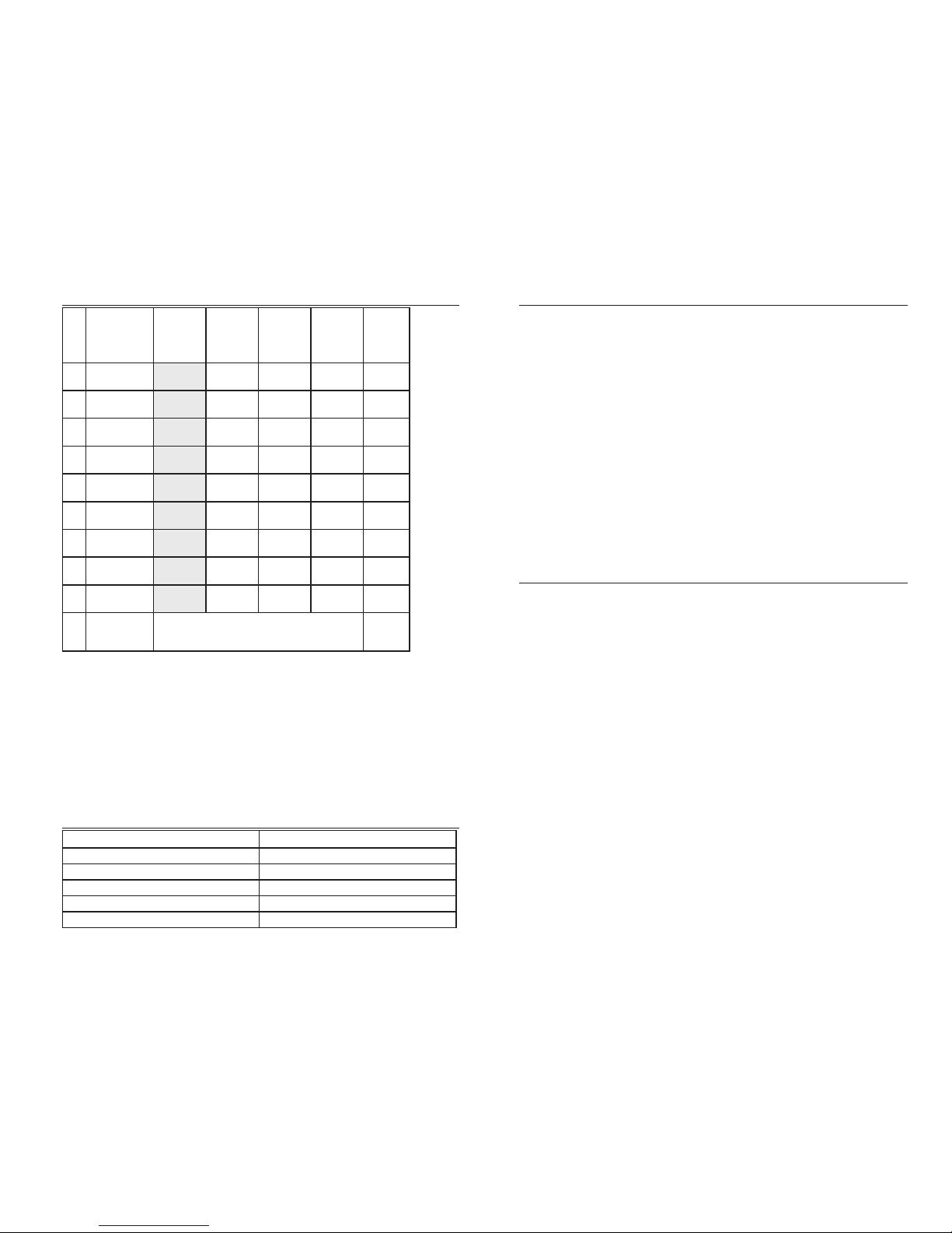
4.A PROGRAMMABLE FEATURE TABLE
FEATURES
LOCK:
Siren chirp
once
LED flash
once
UNLOCK:
Siren chirp
twice
LED flash
twice
PANIC:
Siren chirp
3 times
LED flash 3
times
AUX:
Siren chirp
4 times
LED flash 4
times
Siren
Chirp
Indicator
1
Lock / Unlock
Pulse
Single* Double 1 Short
Chirp
2
Disarm Parking
Light O/P
Flash
Twice*
Light
30 sec
1 Short
Chirp
3
Disarm
(1st AUX)
Trunk* Car Start
(see Note 1)
1 Short
Chirp
4
2nd AUX / Horn
Pulse*
(see Note 2)
Latch
(see Note 3)
Horn
(see Note 4)
Limited Horn
(see Note 5)
1 Short
Chirp
5
IGN Lock /
Unlock
On* Off 1 Short
Chirp
6
Keyless Entry Off* On 1 Short
Chirp
7
IGN Anti
Hi-Jack
Off* On
Note 6
1 Short
Chirp
8
Door
Anit Hi-Jack
Off* On 1 Short
Chirp
9
Remote Anit
Hi-Jack
Off* On 1 Short
Chirp
10
Back to
Factory Default
Press AUX for 3 seconds. Siren will chirp 6 times.
Light will flash 6 times. All features will be returned
to default settings.
1 Short
Chirp
*All settings shaded in gray are factory default settings.
Note 1: CAR START – Press and release AUX button to get a 0.5 second negative output
on the 1st channel (trunk release wire). This will bypass the sensor and ignition.
Note 2: PULSE – Press and hold the LOCK and PANIC buttons, and the 2nd Channel
Output will send signal as long as the LOCK and PANIC buttons are held.
Note 3: LATCH – Press LOCK and PANIC buttons for a 30 second signal output.
Note 4: HORN – The Horn wire will have an output whenever the Siren wire has an output.
Note 5: LIMITED HORN – The Horn will sound only during Door Trigger, Ignition, or when
the Shock Sensor is triggered. The siren will sound/chirp on all events.
Note 6:
If ignition hi-jack is enabled, you must disable hi-jack using the valet button before
entering programming mode. Leave ignition on after turning off hi-jack.
See ignition hi-jack on page 8.
4.B LED INDICATION TABLE
Type of Trigger in Armed Mode LED Status
No Trigger LED Flash rapidly (Auto Rearm Activated)
Ignition 1 Flash & 1 Pause
Pin Switch Zone 2 Flash & 1 Pause
Door Zone 3 Flash & 1 Pause
Sensor Zone 4 Flash & 1 Pause
Page 4

Pin #8: GREEN = Negative Trigger Door Input (–)
• This Input will trigger the Alarm if it becomes Grounded while
alarm is armed (if door is opened).
Pin #9: N/A
Pin #10: PURPLE = Positive Trigger Door Input (+)
• This Input will trigger the Alarm if it receive +12 Volts while alarm
is armed (if door is opened).
Pin #11: ORANGE = Starter Kill Output (–)
• This output needs to be used with a relay to be cut into the
vehicle starter wire.
Pin #12: BLUE = Hood Pin Input (–)
• This Input will trigger the Alarm if it becomes Grounded while
alarm is armed (if the hood is opened).
Pin #13: BROWN/WHITE = 2nd Auxiliary or horn honk output.
Note: Controlled through programmable feature #4.
Pin #14: N/A
Pin #15: BLACK/WHITE = Dome Light Supervision (–)
• This wire will provide a 0-60 sec for illuminated vehicle
when Alarm is Disarmed.
Pin #16: N/A
2.C SHOCK SENSOR
Adjust Sensitivity for best protection.
1. If car receives light Impact, siren / horn will chirp 5 times in quick
succession and Parking Light will Flash once for warning purpose.
2. If car receives heavy impact, siren / horn will sound and Parking
Lights will Flash for 60 sec.
NOTE: Shock Sensor will sound maximum of 5 times, then will reset
to deactive until armed again.
4
2.B POWER HARNESS WIRING CONFIGURATION
CONTINUED
5
2.D 2 PIN HARNESS(LOCK/UNLOCK)
WIRING CONFIGURATION
GREEN:(-) Connect this Wire to Vehicle Lock Wire.
BLUE: (-) Connect this Wire to Vehicle Unlock Wire.
Note: For vacuum operated door lock system remove jumper pin #4.
Use Optional Part RRAL-DL to add door lock on-board relay interface.
3. VALET OVERRIDE SWITCH OPERATION
The Valet switch has five functions:
• To Program Remote Controls (see Section 1 – How to “Code
Learn” a Remote Control)
• To Program the “Programmable Features” (see Section 4 –
Programmable Features)
• Basic Keyless Entry Mode
• With Ignition ON, hold Valet switch for 5 seconds (repeat to exit).
• Only locks and unlocks doors; Horn and siren only work in
“Panic Mode”. LED steady on.
• NOTE: This is different from Programmable Feature #6, which
does Keyless Entry where all features work except door, hood,
and shock sensor triggers.
• To Stop Panic Mode if Remote is Lost or Not Present
• With Ignition ON, hold Valet switch until Horn/Siren stops.
• To Exit from Hi-jack mode
• Turn on ignition, then press override switch for 1 sec. The system will be in disarm mode.
4. PROGRAMMABLE FEATURES
To change any of the programmable features, please follow these steps.
1. Turn ignition ON.
2. Press Valet Override switch 5 times – the siren / horn will chirp
once and parking light and LED will stay on.
3. Press the Valet switch the number of times equal to the number of
the feature to be programmed
4. Press the button to be programmed (LOCK, UNLOCK, PANIC, AUX)
on the remote to choose the setting you desire.
5. Turn ignition OFF.
Note: If 10 seconds expire without any programming activity, the
parking light and LED will turn OFF, and the System will return to
Disarm mode.
 Loading...