

MICREL SY89429A Datasheet
PROGRAMMABLE
T
A
D
FREQUENCY SYNTHESIZER
(25MHz to 400MHz)
ClockWorks™
SY89429A
FEATURES
■ Improved jitter performance over SY89429
■ 25MHz to 400MHz differential PECL outputs
■ ±25ps peak-to-peak output jitter
■ Minimal frequency over-shoot
■ Synthesized architecture
■ Serial 3 wire interface
■ Parallel interface for power-on
■ Internal quartz reference oscillator driven by quartz
crystal or PECL source
■ PECL output can operate with either +3.3V or +5V
VCC_OUT power supply
■ External loop filter optimizes performance/cost
■ Applications note (AN-06) for ease of design-ins
■ Available in PLCC and SOIC 28-pin packages
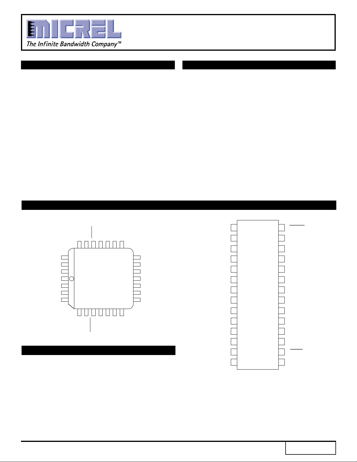
PIN CONFIGURATION
S
_CLOCK
S_DAT
S_LOA
VCC_QUIE
LOOP _FILTER
LOOP_REF
XTAL1
CC_OUT
V
FOUT
25 24 23 22 21 20 19
26
27
28
1
2
3
4
TOP VIEW
567891011
VCC1
XTAL2
FOUT
PLCC
_LOAD
P
GND
M[0]
CC (TTL)
V
M[1]
TEST
GND (TTL)
M[3]
M[2]
18
N[1]
17
N[0]
16
M[8]
15
M[7]
14
M[6]
13
M[5]
12
M[4]
APPLICATIONS
■ Workstations
■ Advanced communications
■ High end consumer
■ High-performance computing
■ RISC CPU clock
■ Graphics pixel clock
■ Test equipment
■ Other high-performance processor-based
applications
DESCRIPTION
The SY89429A is a general purpose, synthesized clock
source targeting applications that require both serial and
parallel interfaces. Its internal VCO will operate over a
range of frequencies from 400MHz to 800MHz. The
differential PECL output can be configured to be the VCO
frequency divided by 2, 4, 8 or 16. With the output configured
to divide the VCO frequency by 2, and with a 16MHz
external quartz crystal used to provide the reference
frequency, the output frequency can be specified in 1MHz
steps.
M[0]
M[1]
M[2]
M[3]
M[4]
M[5]
M[6]
M[7]
M[8]
N[0]
N[1]
GND (TTL)
TEST
CC
(TTL)
V
1
2
3
4
5
6
7
8
9
10
11
12
13
14
TOP VIEW
SOIC
Z28-1
28
P
_LOAD
27
V
CC1
26
XTAL
2
25
XTAL
1
24
LOOP
_REF
23
LOOP
_FILTER
22
V
CC_QUIET
21
S
_LOAD
20
S
_DATA
19
S
_CLOCK
18
V
CC_OUT
17
FOUT
16
FOUT
15
GND
Rev.: H Amendment: /0
1
Issue Date: October, 1998

Micrel
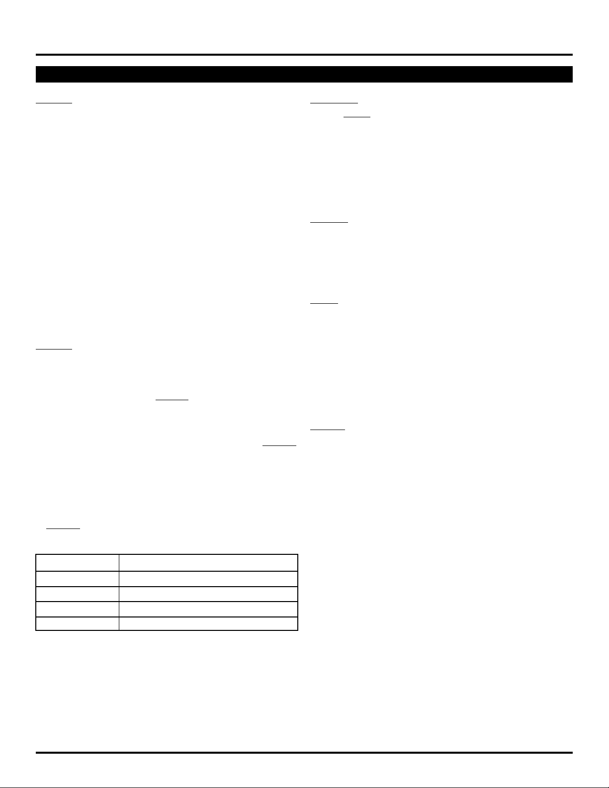
BLOCK DIAGRAM
ClockWorks™
SY89429A
+5.0V
÷ 8
10-25MHz
Fundamental
Crystal
or
OSC
PECL
Source
3 WIRE
INTERFACE
DETAILED BLOCK DIAGRAM
LOOP_FILTER
F
REF
PHASE DETECTOR
PLL
VCO
PECL
÷ M
400 – 800
÷ N
MHz
SERIAL
PARALLEL
INTERFACE
LOGIC
CONFIG INFO
+5.0V
23 1
LOOP_REF
V
CC_QUIET
+5.0V
V
CC1
FOUT
TEST
6, 21
÷ 8
10–25MHz
Fundamental
Crystal
or
PECL
Source
S_
S_
P_
S_
LOAD
LOAD
DATA
CLOCK
4
XTAL1
5
28
7
27
26
OSC
XTAL2
NOTE:
Pin numbers reference PLCC pinout.
FREF
PHASE DETECTOR
COUNTER
L = LATCH
H = Transparent
9-BIT SR
8 -> 16
400-800
VCO
10
9-BIT ÷ M
LATCH LATCH
01
9
M[8:0]
MHz
T110
(2,4,8,16)
01
2-BIT SR
17,18
÷ N
N[1:0]
+5.0V
V
CC_OUT
÷ M —
LOW —
FOUT —
÷ M —
FREF —
HIGH —
7
6
5
4
3
2
1
0
FOUT ÷ 4 —
CLOCK
S_
LATCH
3-BIT SR
19,22
2
25
24
FOUT
23
FOUT
20
TEST
2
Micrel
PIN DESCRIPTIONS
ClockWorks™
SY89429A
INPUTS
XTAL1, XTAL2
These pins form an oscillator when connected to an external
crystal. The crystal is series resonant. Alternatively, these
pins can be driven with 100K PECL level by an external
source.
S_LOAD
This TTL pin loads the configuration latches with the contents
of the shift registers. The latches will be transparent when this
signal is HIGH; thus, the register data must be stable on the
HIGH-to-LOW transition of S_LOAD for proper operation.
S_DATA
This TTL pin is the input to the serial configuration shift
registers.
S_CLOCK
This TTL pin clocks the serial configuration shift registers. On
the rising edge of this signal, data from S_DATA is sampled.
P_LOAD
This TTL pin loads the configuration latches with the contents
of the parallel inputs. The latches will be transparent when this
signal is LOW; thus, the parallel data must be stable on the
LOW-to-HIGH transition of P_LOAD for proper operation.
OUTPUTS
FOUT, FOUT
These differential positive-referenced ECL signals (PECL)
are the output of the synthesizer.
TEST
The function of this TTL output is determined by the serial
configuration bits T[2:0].
POWER
VCC1
This is the positive supply for the chip and is normally connected
to +5.0V.
VCC_OUT
This is the positive reference for the PECL outputs, FOUT and
FOUT. It is constrained to be less than or equal to VCC1.
VCC_QUIET
This is the positive supply for the PLL and should be as noisefree as possible for low-jitter operation.
GND
These pins are the negative supply for the chip and are
normally all connected to ground.
M[8:0]
These TTL pins are used to configure the PLL loop divider.
They are sampled on the LOW-to-HIGH transition of P_LOAD.
M[8] is the MSB, M[0] is the LSB. The binary count on the M
pins equates to the divide-by value for the PLL.
N[1:0]
These TTL pins are used to configure the output divider
modulus. They are sampled on the LOW-to-HIGH transition
of P_LOAD.
N[1:0] Output Division
0 0 2
0 1 4
1 0 8
1 1 16
OTHER
LOOP_FILTER
This is an analog I/O pin that provides the loop filter for the
PLL.
LOOP_REF
This is an analog I/O pin that provides a reference voltage for
the PLL.
3
 Loading...