

Micrel SY87729L, SY87739L User Manual
Micrel, Inc.
SY87729L 10MHz to 365MHz
SY87739L 10MHz to 729MHz
FRACTIONAL-N SYNTHESIZERS
SY87729/39L
SuperCOM™
Evaluation Board
SY87729L
SY87739L
Evaluation Board
FEATURES
■ DC coupled and terminated PECL inputs
■ AC coupled PECL outputs
■ Programmable via any PC using printer cable
■ Includes a 27.0000MHz oscillator on board
EVALUATION BOARD COMPONENTS
■ SY87729/39L evaluation board
■ SY87729/39L data sheet and this document
■ SY87729/39L software (download from
http://www.micrel.com/product-info/
fractional_n_synthesizers.shtml)
■ Two length-matched 1 foot SMA cables (optional,
user supplied)
■ PC running Windows (user supplied)
■ Printer cable, parallel-to-centronics (user supplied)
DESCRIPTION
The SY87729/39L are rate independent fractional-N
frequency synthesizer ICs. From a single reference source,
they can generate any clock frequency from 10MHz to
729MHz very accurately.
This document provides a detailed description of the
evaluation board, evaluation procedure and the simple
configuration software it uses. Complete information in this
document includes:
1. Test setup and measuring frequency output with
a signal generator.
2. Test setup and measuring jitter with an internal
reference oscillator.
3. Download and use of the configuration software
4. Board schematic and Bill of Materials.
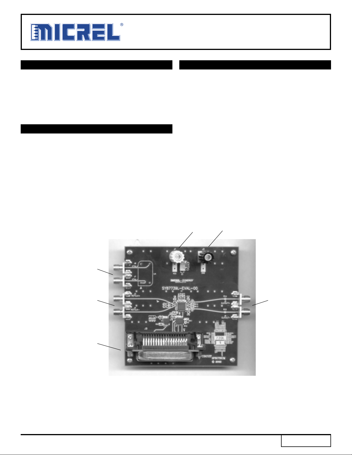
Power
Banana Jack
(J1)
Ground
Banana Jack
(J2)
Reference
Oscillator
Outputs
Reference
Clock Inputs
Centronics
Programming Port
Synthesized
Clock Outputs
SuperCOM is a trademark of Micrel, Inc.
M9999-071906
hbwhelp@micrel.com or (408) 955-1690
1
Rev.: B Amendment: /0
Issue Date: July 2006
Micrel, Inc.
SY87729/39L
Evaluation Board
GETTING STARTED
Before powering up the SY87729/39L evaluation board,
you must do the following:
1. Familiarize yourself with the SY87729/39L
evaluation board.
2. Make sure that you are properly grounded.
3. Read and understand this document in its
entirety.
To program the desired output frequency, you will need
a PC running Windows, with the SY87729/39L evaluation
board software installed, and a printer cable attached
between the PC and the SY87729/39L evaluation board.
The software downloads configuration information to the
SY87729/39L device.
If using an external signal source, that source must be
able to generate LVPECL level signals. The inputs are DC
coupled, terminated in 50Ω to VCC–2V.
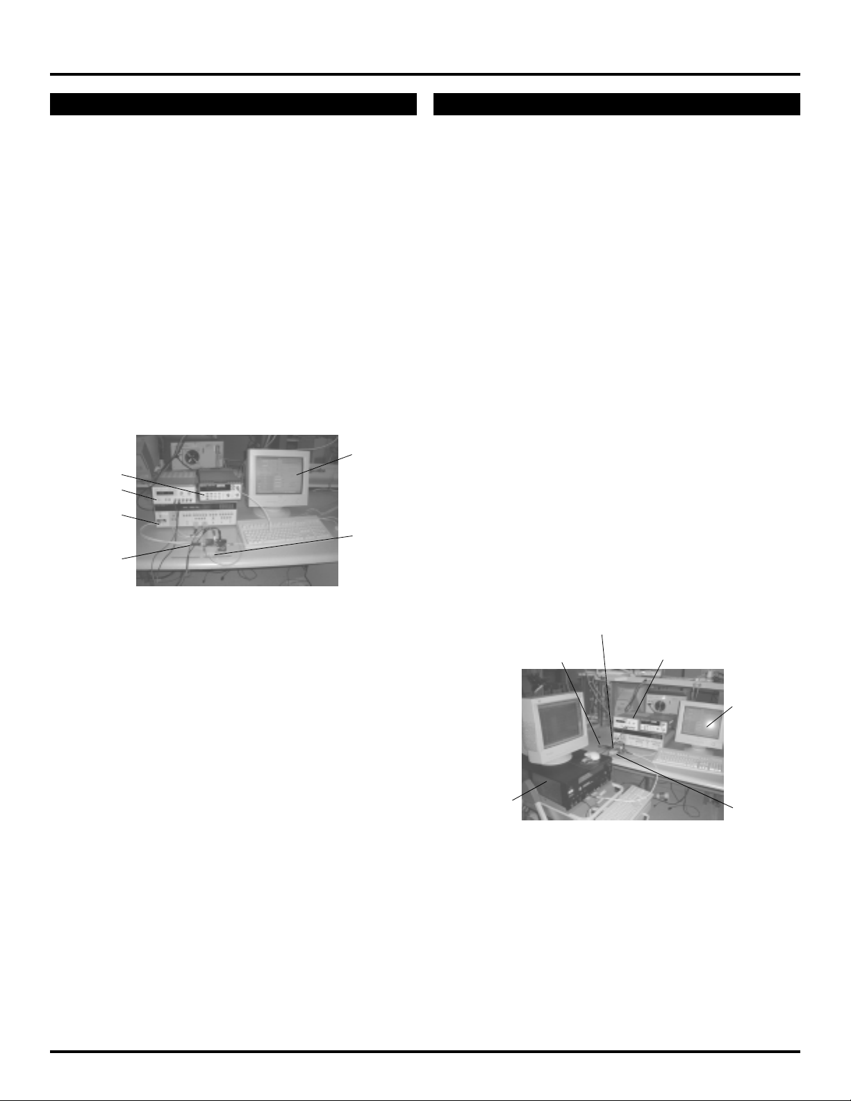
PC Running
Frequency
Counter
Power
Supply
Signal
Generator
SY87729/39L
Evaluation
Board
Figure 1. Test Set-Up with
Signal Generator
Download
Application
Printer
Cable
TEST SET-UP
This section discusses how to make two common
measurements with the SY87729/39L evaluation board.
What you will need:
1. The SY87729/39L evaluation board.
2. Either two length-matched one foot SMA cables,
or a digital signal generator such as the
HP8133A.
3. A PC with a parallel port, running Windows.
4. If you are running Windows NT, Windows 2000,
or Windows XP, you will need “Direct-IO”
shareware.
5. A printer cable, one end is a parallel interface,
the other end is a Centronics interface.
6. The SY87729/39L evaluation board software
(download from http://www.micrel.com).
7. A frequency counter.
8. A power supply capable of delivering at least
3.3V at 0.5A.
9. A self-triggering scope or a time interval analyzer
(TIA).
First, we show how to use an external signal generator and
how to measure the frequency of the output. Second, we
show how to use the supplied reference oscillator and how
to measure cycle-to-cycle jitter of the output. Please refer to
Figures 1 and 2.
SY87729/39L
Evaluation Boad
Time Interval
Analyzer (TIA)
Power SupplyPatch Cables
Figure 2. Test Set-Up with
Internal Reference Oscillator
PC Running
Download
Application
Printer
Cable
M9999-071906
hbwhelp@micrel.com or (408) 955-1690
2

Micrel, Inc.
EVALUATION PROCEDURE
SY87729/39L
Evaluation Board
Downloading the Application Software
Micrel’s SY87729/39L accepts configuration information
via a bit-serial interface. To program the device, the user
must download 32 bits of configuration information into
SY87729/39L. Micrel provides a download application for
use with the SY87729/39L evaluation board.
With this software, the user may select any desired output
frequency that the SY87729/39L can generate, between
10MHz and 729MHz. The software will automatically
determine the configuration parameters that most accurately
generate the desired frequency. These parameters,
explained in the data sheets, may be viewed or modified.
They may also be downloaded to the SY87729/39L-EVAL
circuit board through a printer cable attached between the
PC and the SY87729/39L evaluation board.
To download the software, point your web browser to the
following URL, and save the files to your PC: You should
download the applications “739ifier”, “739ev” and “739ev2.”
http://www.micrel.com/page.do?page=product-info/
fractional_n_synthesizers.shtml
Installing the Application Software
Create a folder just for these applications. Download all
three application files into this folder.
Running Win95, Win98, or WinME
If you are running any of these Windows operating
systems, you have completed downloading all the software
you will need. You will not need the application file “739ev2”
and may delete it at your convenience. The application file
“739ev” allows you to access one of two parallel ports, the
default one located at base I/O address 0x378 (usually
known as LPT1) and a secondary one located at base I/O
address 0x278 (usually known as LPT2).
The application program “739ev2” is identical to
application file “739ev”, except that it defaults to using LPT2
first. This is of no use to the user when running Win95,
Win98, or WinME. Please proceed to the section “Using the
Application Software.”
Running WinNT, Win2000, or WinXP
Besides downloading the applications, you must also
decide what parallel port or ports you will use the applications
with. Since WinNT, Win2000, and WinXP do not permit
direct access to the I/O ports, you must also download and
install a shareware to allow this.
The usual case is to allow downloads on the default
parallel port, LPT1. You may instead decide to allow
downloads only on LPT2, if your computer is equipped with
a second parallel port or you may also decide to allow two
SY87729/39L-EVAL boards to be attached, one to each
LPT1 and LPT2. Table 1 details the I/O ports you must
allow access to, based on which parallel port or ports you
will use with SY87729/39L evaluation board.
Case Base I/O Addresses Needed
Access to LPT1 0x378-0x37A, 0x778-0x77A
Access to LPT2 0x278-0x27A, 0x678-0x67A
Access to both LPT1 and LPT2 0x278-0x27A, 0x378-0x37A,
0x678-0x67A, 0x778-0x77A
Table 1. I/O Addresses to Use
Once you have decided which parallel port or ports you
will connect the SY87729/39L evaluation board to, you must
choose which download application file to keep. If you will
access either LPT1 only, or both LPT1 and LPT2, then
delete the application “739ev2” at this time. If you will access
only LPT2, then delete the application “739ev” at this time,
and then rename the application “739ev2” to “739ev.”
Now, you must download a shareware called “Direct-IO”
that allows the SY87729/39L evaluation board software
application access to the parallel ports at a low level. The
“Direct-IO” shareware is available at:
http://www.direct-io.com
At the time of this writing, you have a free 30-day trial
evaluation period, after which time you must have it
registered. After you have completed download of “Direct-
IO," you must install the program. Follow the installation
instructions for that program. Please note that, in some
cases, the install may fail. In this case, you will need a
systems administrator to install “Direct-IO” for you.
As the final step of application installation, you must
configure “Direct-IO” to give the SY87729/39L evaluation
board software permission to access to the appropriate I/O
addresses. This is accomplished through its control panel.
To access the “Direct-IO” control panel, select:
Start ➯ Programs ➯ Direct IO ➯ Control Panel
If not already active, click the “I/O Ports” tab. The “Hex”
button should already be pressed. You must enter the
appropriate address ranges in the “Begin” and “End” edit
boxes, and then push the “Add” button. The goal is to have
the required I/O addresses appear in the “Active Ports”
section of the “Direct-IO” control panel. For example, to
allow access only to LPT1, you must allow access to two
ranges of I/O addresses. The first range is 0x378-0x37A.
Thus, you type “378” in the “Begin” edit box, and you type
“37A” in the “End” edit box. The “Direct-IO” control panel
should look like Figure 3.
M9999-071906
hbwhelp@micrel.com or (408) 955-1690
3
Micrel, Inc.
SY87729/39L
Evaluation Board
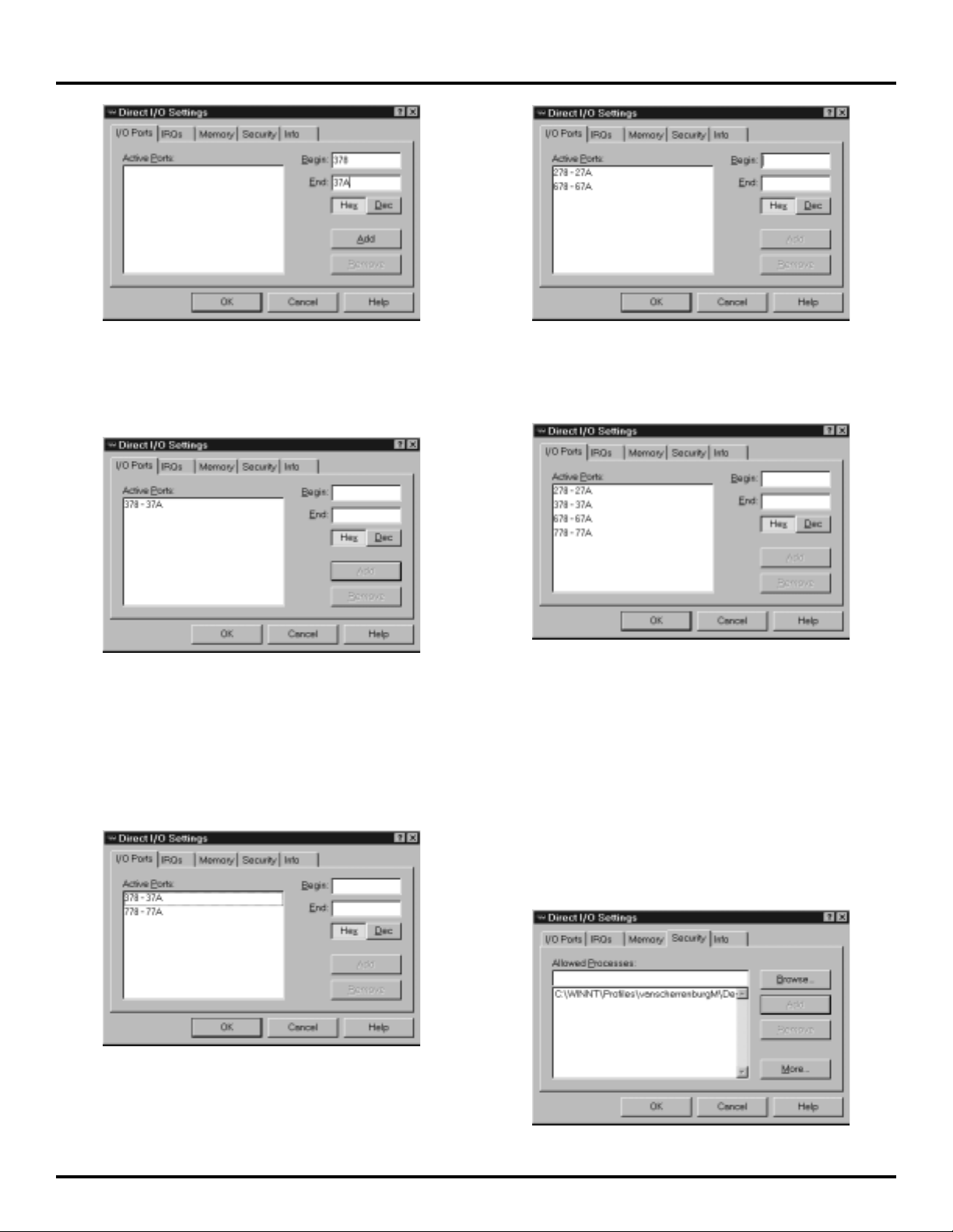
Figure 3. Filling in the I/O Ports Tab
You then click the “Add” button. This selects the range of
I/O addresses specified, and places it into the “Active Ports”
Window, as shown in Figure 4.
Figure 4. After pressing the “Add” Button
To continue with this example, the SY87729/39L
evaluation board application also needs access to I/O
addresses 0x778 through 0x77A. Thus, type “778” in the
“Begin” edit box, and type “77A” in the “End” edit box. Then
click the “Add” button. The “Direct-IO” control panel should
look like Figure 5.
Figure 6. Correct I/O Addresses for LPT2 Access
Finally, to access both LPT1 and LPT2, the “Direct-IO”
control panel should look like Figure 7.
Figure 7. Correct I/O Addresses for both LPT1
and LPT2 Access
After entering the I/O addresses to allow access to, you
must specify the program or programs allowed to access
these I/O locations. Click the “Security” tab. Click the
“Browse...” button. Select the directory into which you placed
the SY87729/39L evaluation board application programs,
and select the application, “739ev.” The path and application
will appear in the “Allowed Processes:” edit box. Click the
“Add” button to include “739ev” in the list of allowed
programs. The “Direct-IO” control panel should look like
Figure 8, except that the path will be whatever you chose.
Figure 5. Correct I/O Addresses for LPT1 Access
Consulting Table 1, If you are accessing only LPT2, the
“Direct-IO” control panel should look like Figure 6.
M9999-071906
hbwhelp@micrel.com or (408) 955-1690
Figure 8. Including “739ev” in the List of Allowed
Processes
4
 Loading...