

MICREL SY10E196, SY100E196 Datasheet
PROGRAMMABLE DELAY
CHIP WITH ANALOG INPUT
ClockWorks™
SY10E196
SY100E196
FEATURES
■ Up to 2ns delay range
■ Extended 100E V
EE range of –4.2V to –5.5V
■ ≈20ps digital step resolution
■ Linear input for tighter resolution
■ >1GHz bandwidth
■ On-chip cascade circuitry
■ 75KkΩ input pulldown resistor
■ Fully compatible with Motorola MC10E/100E196
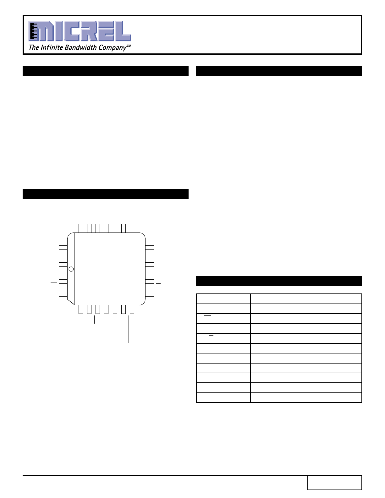
■ Available in 28-pin PLCC package
PIN CONFIGURATION
7
5
3
4
D
D
PLCC
J28-1
EN
SET MIN
6
D
D
NC
SET MAX
CASCADE
CASCADE
18
FTUNE
17
NC
16
V
CC
15
V
CCO
14
Q
13
Q
12
V
CCO
D
D
LEN
V
EE
IN
IN
V
BB
2
D
D
25
24 23 22 21 20 19
26
1
27
0
28
1
2
3
4
TOP VIEW
567891011
NC
NC
DESCRIPTION
The SY10/100E196 are programmable delay chips
(PDCs) designed primarily for very accurate differential
ECL input edge placement applications.
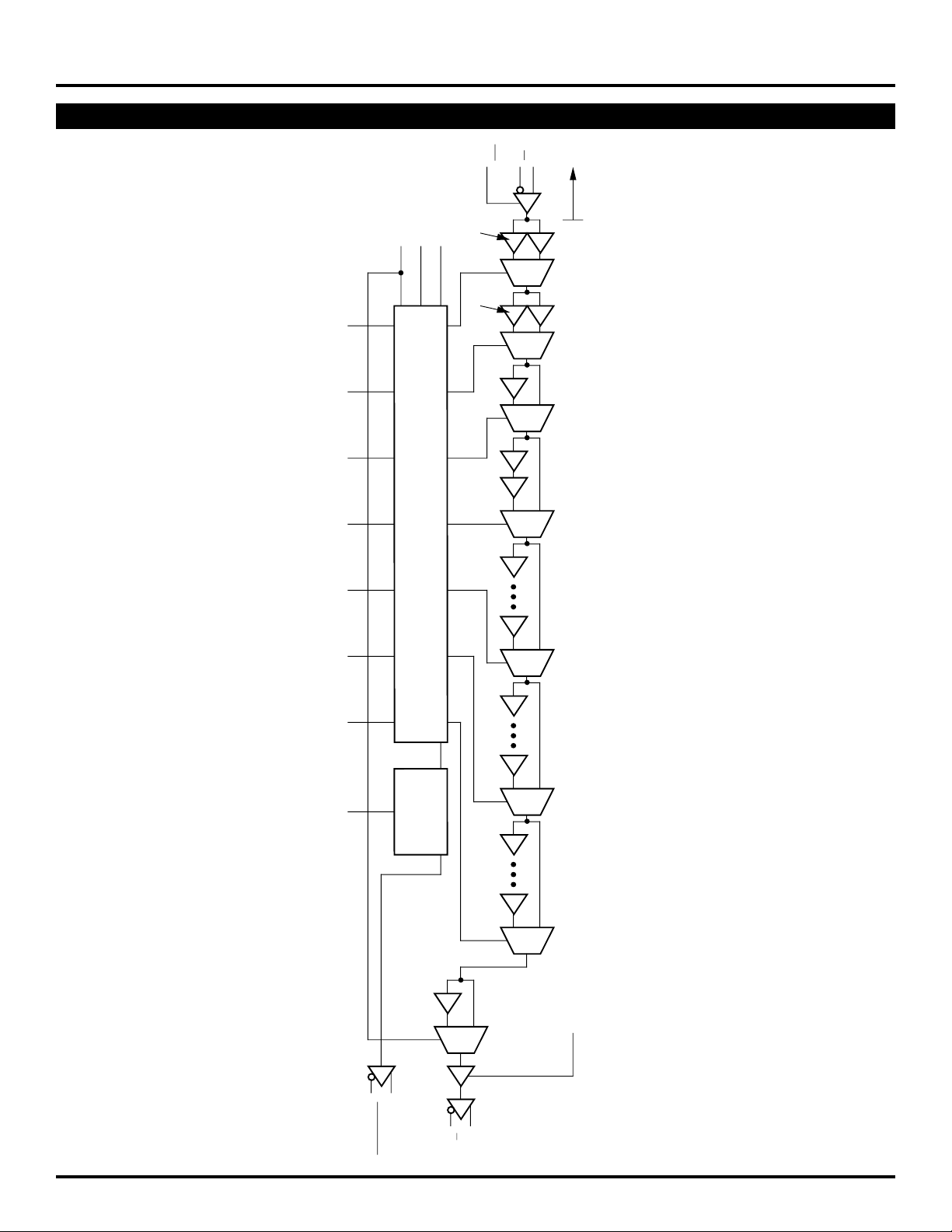
The delay section consists of a chain of gates and a
linear ramp delay adjustment organized as shown in the
logic diagram. The first two delay elements feature gates
that have been modified to have delays 1.25 and 1.5
times the basic gate delay of approximately 80ps. These
two elements provide the E196 with a digitally-selectable
resolution of approximately 20ps. The required device
delay is selected by the seven address inputs D[0:6],
which are latched on-chip by a high signal on the latch
enable (LEN) control. If the LEN signal is either LOW or
left floating, then the latch is transparent.
The FTUNE input takes an analog coltage and applies
it to an internal linear ramp for reducing the 20s resolution
still further. The FTUNE input is what differentiates the
E196 from the E195.
An eighth latched input, D7, is provided for cascading
multiple PDCs for increased programmable range. The
cascade logic allows full control of multiple PDCs, at the
expense of only a single added line to the data bus for
each additional PDC, without the need for any external
gating.
PIN NAMES
Pin Function
IN/IN Signal Input
EN Input Enable
D[0:7] Mux Select Inputs
Q/Q Signal Output
LEN Latch Enable
SET MIN Minimum Delay Set
SET MAX Maximum Delay Set
CASCADE Cascade Signal
FTUNE Linear Voltage Input
V
CCO VCC to Output
Rev.: E Amendment: /0
1
Issue Date: October, 1998
Micrel
ClockWorks™
SY10E196
SY100E196
BLOCK DIAGRAM
EN
IN
SET MAX
SET MIN
LEN
*1.25
1
*1.5
D
0
D
1
D
2
7-Bit Latch
D
3
1
1
1
1
1
1
VBB
IN
1
0
1
0
0
0
*Delays are 25% or 50% longer than
standard (standard = 80ps).
D
4
D
5
D
6
LEN
D
7
D
Latch
Q
Cascade
1
4 gates
1
8 gates
1
16 gates
1
0
0
0
FTUNE
CASCADE
CASCADE
Ramp
Linear
1
0
Q
Q
2

ClockWorks™
SY10E196
Micrel
SY100E196
DC ELECTRICAL CHARACTERISTICS
VEE = VEE (Min.) to VEE (Max.); VCC = VCCO = GND
TA = 0°CTA = +25°CTA = +85°C
Symbol Parameter Min. Typ. Max. Min. Typ. Max. Min. Typ. Max. Unit Condition
IIH Input HIGH Current — — 150 — — 150 — — 150 µA—
EE Power Supply Current mA —
I
10E — 130 156 — 130 156 — 130 156
100E — 130 156 — 130 156 — 150 179
3
 Loading...