

MICREL SY10E150, SY100E150 Datasheet

6-BIT D
LATCH
SY10E150
SY100E150
FEATURES
■ 700ps max. propagation delay
■ Extended 100E V
EE range of –4.2V to –5.5V
■ Differential outputs
■ Fully compatible with industry standard 10KH,
100K ECL levels
■ Internal 75KΩ input pulldown resistors
■ Fully compatible with Motorola MC10E/100E150
■ Available in 28-pin PLCC package
BLOCK DIAGRAM
0
D
D
R
D
1
D
R
D
2
D
R
D
3
D
R
D
4
D
Q
0
Q
0
Q
1
Q
1
Q
2
Q
2
Q
3
Q
3
Q
4
DESCRIPTION
The SY10/100E150 are 6-bit D latches with differential
outputs designed for use in new, high- performance ECL
systems. When both Latch Enables (LEN1, LEN2) are at a
logic LOW, the latch is in the transparent mode and input
data propagates through to the output. A logic HIGH on
either LEN1 or LEN2 (or both) latches the input data. The
Master Reset (MR) overrides all other signals to set the Q
outputs to a logic LOW.
PIN CONFIGURATION
1
2
MR
LEN
LEN
24 23 22 21 20 19
25
26
D
5
27
D
4
28
D
3
V
EE
1
D
2
2
D
1
3
D
0
4
567891011
NC
CCO
V
PLCC
TOP VIEW
J28-1
NC
0Q0
Q
CCO
V
1
Q
5
5
Q
Q
18
Q
4
17
Q
4
16
V
CC
15
Q
3
14
Q
3
13
Q
2
12
Q
2
1
Q
CCO
V
LEN
LEN
MR
Q
R
D
5
D
R
1
2
4
Q
5
Q
5
PIN NAMES
Pin Function
D0–D5 Data Inputs
LEN1, LEN2 Latch Enables
MR Master Reset
Q0–Q5 True Outputs
Q0–Q5 Inverting Outputs
V
CCO VCC to Output
Rev.: D Amendment: /0
1
Issue Date: November, 1998
Micrel
SY10E150
SY100E150
TRUTH TABLE
(1)
(Each Latch)
INPUTS OUTPUTS Operating
Dn LEN1 LEN2 MR Qn Qn Mode
H L L L H L Latch
LLLLLH
X X H L Latched
X H X L Latched
(2)
(2)
Latched
Latched
(2)
(2)
X X X H L H Asynchronous
NOTES:
1. H = HIGH state
L = LOW state
X = Don’t care
2. Retains Data that is present before the LEN positive transition.
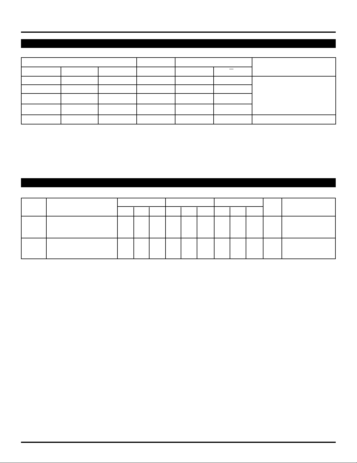
DC ELECTRICAL CHARACTERISTICS
VEE = VEE (Min.) to VEE (Max.); VCC = VCCO = GND
TA = 0°CTA = +25°CTA = +85°C
Symbol Parameter Min. Typ. Max. Min. Typ. Max. Min. Typ. Max. Unit Condition
IH Input HIGH Current µA —
I
D ——200 ——200 ——200
LEN MR ——150 ——150 ——150
EE Power Supply Current mA —
I
10E — 52 62 — 52 62 — 52 62
100E — 52 62 — 52 62 — 60 72
2
 Loading...