

S
General Description
MIC79110
Simple 1.2A Linear Li-Ion Battery Charger
Features
The Micrel MIC79110 is a simple and accurate lithium ion
battery charger. The part features a built-in pass transistor,
precision programmable current limiting (±5%), and
precision voltage termination (±0.75% over temperature).
The MIC79110 packs full functionality into a small space.
Other features of the MIC79110 include two independent
indicators: a digital End-of-Charge signal that is
programmable with a resistor to ground, and an analog
current output that is proportional to the output current,
allowing for monitoring of the actual charging current.
Additional features include very low dropout (550mV over
the temperature range), thermal shutdown, and reverse
polarity protection. In the event the input voltage to the
charger is disconnected, the MIC79110 also provides
minimal reverse-current and reversed-battery protection.
Available in both fixed 4.2V and adjustable outputs, the
MIC79110 is offered in the leadless 10-pin 3mm x 3mm
®
MLF
with an operating junction temperature range of
–40˚C to +125˚C.
Data sheets and support documentation can be found on
Micrel’s web site at www.micrel.com.
• Input voltage range: 2.5V to 16V
• High output voltage accuracy of ±0.75%
over –5°C to +60˚C
• Current limit ±5% accurate from –5°C T
+ 125°C
J
• Programmable end-of-charge flag
• Analog output proportional to output current
• Adjustable and fixed 4.2V output
• Low dropout voltage of 550mV at 700mA load, over
temperature
• 1.2A max charge current
• Excellent line and load regulation specifications
• Reverse current protection
• Thermal shutdown and current limit protection
®
• Tiny 10-Pin 3mm × 3mm MLF
package
• Junction temperature range: –40°C to +125°C
Applications
• Cellular phones
• PDAs
• Digital cameras
• Camcorders
• MP3 players
• Notebook PCs
• Portable Meters
• Cradle chargers
• Car chargers
• Battery packs
___________________________________________________________________________________________________________
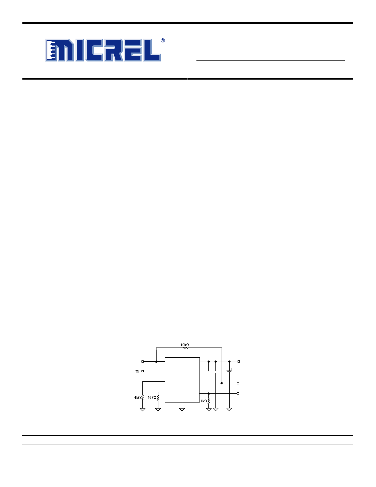
Typical Application
MIC79110
HUTDOWN
ENABLE
V
IN
V
SD
R
R
IN
EOC
SET
GND
BAT
SNS
D
A
EOC
CHG
4.2V
Li-Ion
Cell
4.2V
BAT
MIC79110 Typical Application
MLF and MicroLeadFrame are registered trademarks of Amkor Technology, Inc.
Micrel Inc. • 2180 Fortune Drive • San Jose, CA 95131 • USA • tel +1 (
October 2007
408
) 944-0800 • fax + 1 (408) 474-1000 • http://www.micrel.com
M9999-102507
Micrel, Inc. MIC79110
Ordering Information
Part Number
Standard Marking Pb-Free Marking
Voltage
Junction
Temp. Range
Package
MIC79110-4.2BML L942 MIC79110-4.2YML L942* 4.2V –40° to +125°C 10-pin 3×3 MLF®
MIC79110BML L9AA MIC79110YML L9AA* Adj. –40° to +125°C 10-pin 3×3 MLF®
* Pb-Free “Y” indicator is added to the device mark after LOGO.
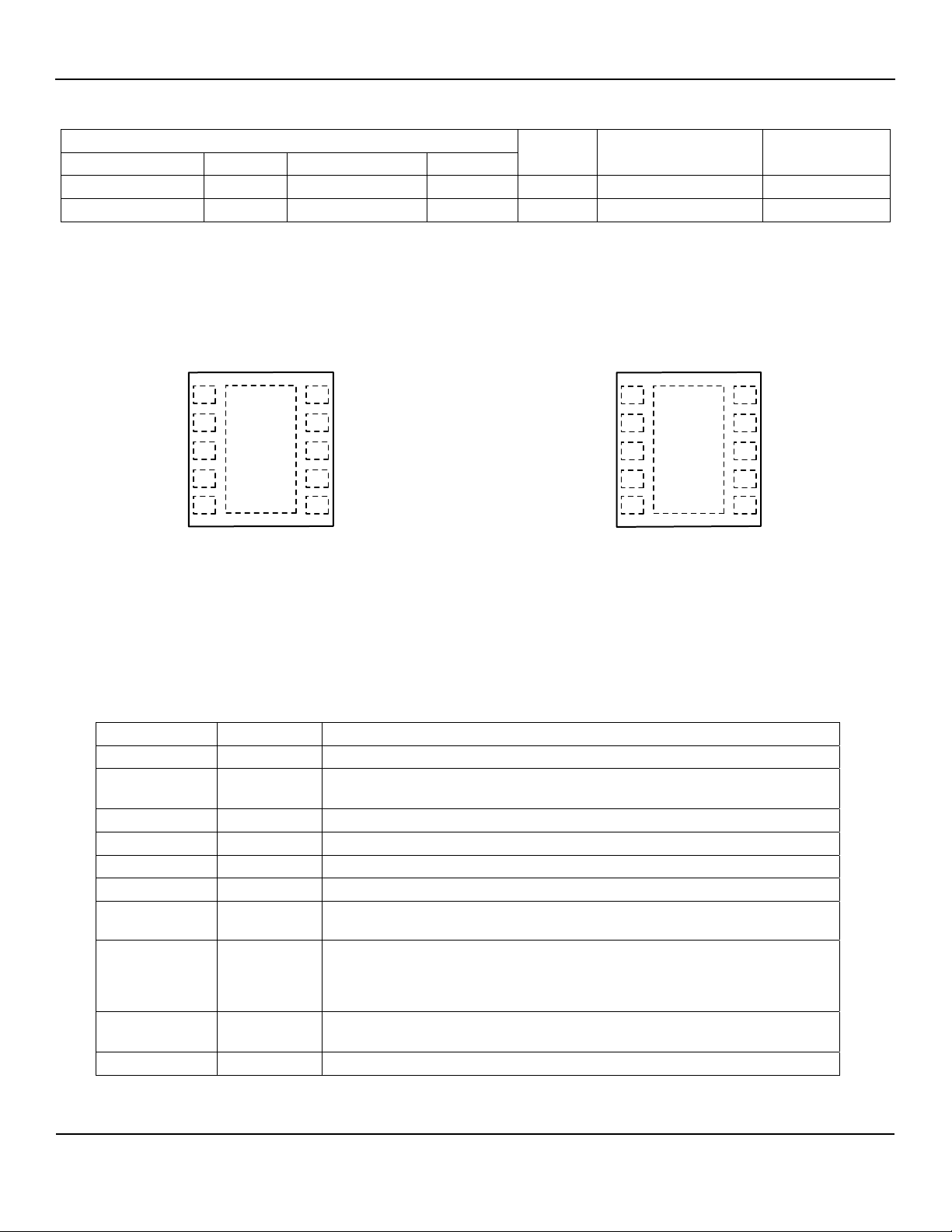
Pin Configuration
1SD
2
R
SET
3
SNS
4
BAT
V
5
IN
Fixed Output
10-Pin 3mm × 3mm MLF
10 GND
R
9
EOC
8
D
EOC
7
A
CHG
V
6
IN
®
(ML)
1SD
R
2
SET
ADJ
3
BAT
4
V
5
IN
10 GND
R
9
EOC
D
8
EOC
A
7
CHG
V
6
IN
Adjustable Output
10-Pin 3mm × 3mm MLF® (ML)
Pin Description
Pin Number Pin Name Pin Function
1 SD Shutdown Input. Logic High = Off; Logic Low = On.
2 RSET
3 SNS (Fixed voltage only): Sense output, connect directly to battery.
3 ADJ (Adjustable voltage only): Feedback input.
4 BAT Battery Terminal. Connect to single-cell lithium-ion battery.
5, 6 VIN Input supply pin.
7 ACHG
8 DEOC
9 REOC
10 GND Ground
Current limit: Sets constant current limit via an external resistor to ground.
IR
= (0.2V/R
SET
Analog Charge Indicator Output: Current source who’s output current is equal to
1/1000 of the BAT pin current.
Digital End-of-Charge Output: N-Ch open drain output. Low indicates charging,
a current that is higher than the programmed current set by R
battery. When the current drops to less than the current set by R
goes high impedance, indicating end-of-charge.
End-of-Charge Set: Sets end-of-charge current threshold via an external resistor
to ground. I
SET
= (0.2V/R
EOC
) × 1000.
EOC
) × 1000.
is charging the
EOC
, the output
EOC
October 2007 2
M9999-102507

Micrel, Inc. MIC79110
Absolute Maximum Ratings
(1)
Operating Ratings
(2)
Input Supply Voltage (VIN).................................... 0V to 18V
Shutdown Input Voltage (V) ................................. 0V to 10V
Output Voltage (ADJ) .....................................................10V
Power Dissipation ...................................Internally Limited
Junction Temperature ...............................–40°C to +125°C
Input Supply Voltage ........................................ 2.5V to 16V
Shutdown Input Voltage (V) ................................... 0V to 7V
Output Voltage (ADJ) .................................................... 9.6V
Junction Temperature Range (T
(MLF-10) .......................................................... 60°C
θ
JA
(MLF-10) ............................................................ 2°C
θ
JC
)............. –40°C to +125°C
J
Electrical Characteristics
TA = 25°C with VIN = V
otherwise specified.
Parameter Condition Min Typ Max Units
Output Voltage Accuracy
ADJ Pin Voltage Accuracy 0.5955 0.6 0.6045 V
Line Regulation
Load Regulation
Dropout Voltage(3)
Ground Current
VIN Pin Current SD = VIN
Shutdown Pin Current SD = 5.2V, V
Shutdown Input Threshold
Shutdown Hysteresis 60 mV
Current Limit Accuracy
Current Limit Setpoint
(5)
Range
Maximum Current Limit
V
Reverse Current VIN = High impedance or ground
BAT
Digital End–of–Charge (D
(6, 7)
I
I
D
D
D
R
R
EOC
(6, 7)
R
EOC
Logic–Low Voltage I
EOC
Leakage Current Logic High = VIN = 16V
EOC
On Resistance VIN = +5V
EOC
Maximum Current Limit R
EOC
Analog Charge Indicator (A
(8)
I
SOURCE
I
I
OUT
+ 1V; I
(4, 5)
EOC
CHG
(4)
= 100µA; C
LOAD
Variation from V
V
= V
+ 1V to 16V @ I
OUT
= 0.1mA to 1A
= 100mA, R
= 700mA, R
= 10mA, R
= 700mA, R
I
LOAD
I
LOAD
I
LOAD
I
LOAD
I
LOAD
IN
Logic High, regulator off
Logic Low, regulator on
V
= 0.9 × V
OUT
R
= 167, TJ = –40°C to +85°C
SET
V
= 0.9 × V
OUT
R
= 2k
SET
= 10µF; SD = 0V; R
BATT
= 4.2V; TJ = –5°C to +60°C; I
OUT
= 50mA -0.1
LOAD
= 167
SET
= 167
SET
= 167
SET
= 167
SET
= 0
BAT
; I
; I
OUT
OUT
= 1.2A,
= 0.1A,
NOM
NOM
=1k. Bold values indicate –40ºC < T
SET
= 50mA
LOAD
-0.75
-1.5
0.3 %
160
375
2 3 mA
24
120
0.1
1.1
-5
-20
< +125°C; unless
J
+0.75
+1.5
+0.1 %/V
250
550
35
300
5
%
%
mV
mV
mA
µA
µA
V
0.9
+5
+20
V
%
%
0.1 1.2 A
R
shorted to ground, V
SET
= 0.9 × V
BAT
NOM
1.25 1.65
4.2
2.5
20
A
µA
) Output
= 4k Current Falling
EOC
= 4k Current Rising
EOC
DEOC
= 5mA, I
= 700mA
BAT
35
50
30
50
70
40
0.74
65
70
95
100
0.95
mA
mA
mA
mA
V
0.1 µA
150 190
shorted to ground
EOC
0.5
1.0
2.0
mA
) Output
= 50mA
BAT
= 1.2A, TJ = –40°C to +85°C
BAT
37
800
46
950
55
1150
µA
µA
October 2007 3
M9999-102507
Micrel, Inc. MIC79110
Notes:
1. Exceeding the absolute maximum rating may damage the device.
2. The device is not guaranteed to function outside its operating rating.
3. Dropout Voltage is defined as the input to output differential at which the output voltage drops 2% below its nominal value measured at 1V
differential. For outputs below 2.5V, dropout voltage is the input-to-output voltage differential with the minimum input voltage 2.5V. Minimum input
operating voltage is 2.5V.
4. V
5. IR
6. Output Current I
7. I
8. I
denotes the nominal output voltage.
NOM
= (0.2V/R
SET
than I
, D
EOC
= (0.2V/R
EOC
is the current output from A
SOURCE
) × 1000
SET
when Digital End-of-Charge output goes high impedance. Currents greater than I
EOC
is high impedance.
EOC
) × 1000
EOC
pin. A resistor to ground from the A
CHG
, the D
EOC
pin will program a voltage that is proportional to the output current.
CHG
output is low, currents lower
EOC
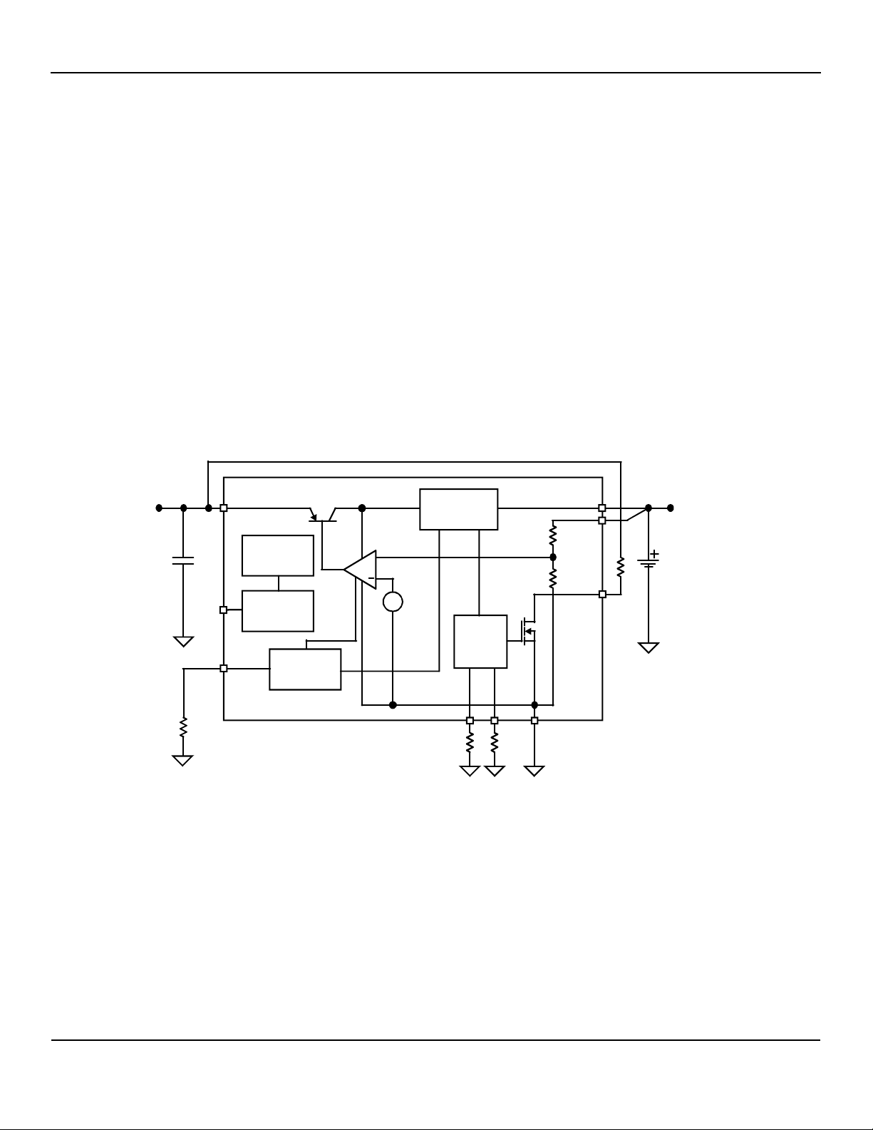
Block Diagram
SD
V
IN
R
SET
Thermal
Protection
Shutdown
Control
Current
Limit Set
Current
Limit Sense
+
V
REF
End of
Charge
Detect
A
CHG
R
MIC79110 Block Diagram
EOC
GND
BAT
SNS
D
EOC
Li-Ion
October 2007 4
M9999-102507
Micrel, Inc. MIC79110
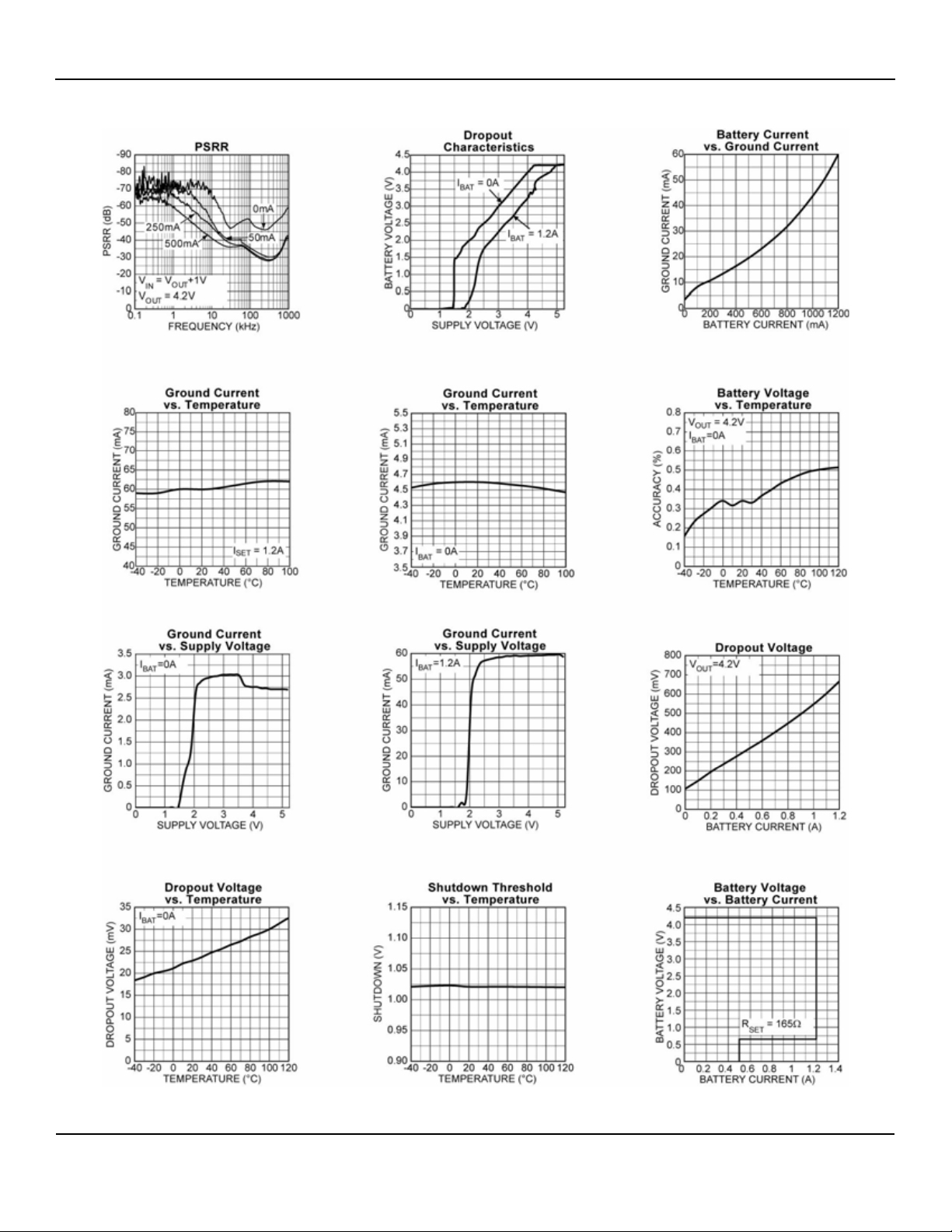
Typical Characteristics
October 2007 5
M9999-102507

Micrel, Inc. MIC79110
Typical Characteristics (continued)
October 2007 6
M9999-102507

Micrel, Inc. MIC79110
Functional Characteristics
October 2007 7
M9999-102507

Micrel, Inc. MIC79110
Application Information
active low, there is reverse battery current protection
built in. The current is limited to less than 10µA over
Detailed Description
temperature.
The MIC79110 forms a complete charger for 1-cell
Lithium-ion batteries. It includes precision voltage control
(0.75% over temperature) to optimize both cell
performance and cycle life. All are compatible with
common 4.2V Lithium-ion chemistries. Voltages other
than 4.2V can be obtained with the adjustable version.
Other features include current limit, end-of-charge flag
and end-of-charge current limit using an external
resistor. The shutdown pin enables low quiescent
current when not charging.
Constant Output Voltage/Current Charging
The MIC79110 features constant voltage and constant
current output to correctly charge lithium-ion batteries.
The constant voltage is either 4.2V or adjustable. The
constant current is set by the R
down to around 300mV. Since R
pin and is constant
set
can be set below
set
500mA, the minimum output current is set at 500mA for
output voltages below 100mV. This minimum voltage
starts the charging process in lithium-ion batteries. If the
output current is too low, the battery will not begin
Current Limit Mode
MIC79110 features an internal current limit that is set by
the RSET pin with a resistor-to-ground. The maximum
charge.
evruCI-V01197CIM
current is calculated by the following equation:
= (0.2/R
IR
set
Using a 167 R
) × 1000
set
resistor will achieve the maximum
set
current limit for the MIC79110 at 1.2 amperes.
End of Charge
R
pin is connected to a resistor-to-ground. This
EOC
resistor is used to set the end of charge current for the
lithium ion battery as follows:
IR
= (0.2/R
EOC
Using a 4k R
EOC
) × 1000
EOC
resistor will set the end-of-charge
current at 50mA.
I
should be set at 10% of the battery’s rated current.
REOC
Digital End-of-Charge Output
This pin is the output of an open drain. When tied high to
the supply using a resistor, the output will toggle high or
low depending on the output current of I
• Low state indicates that the I
current is higher
BAT
than the programmed current set by R
• High state indicates that the I
BAT
than the programmed current set by R
.
BAT
.
EOC
current is lower
. The
EOC
output goes high impedance indicating end-ofcharge.
Analog End-Of-Charge Output
The A
pin provides a small current that is proportional
CHG
to the charge current. The ratio is set at 1/1000th of the
output current.
I Current
evruCI-VdradnatS
= (0.2/R
I
MAX
0.7V
I Current
SET
500mA
)×1000
Lithium Ion Batteries
Lithium-ion batteries are charged in two stages to reach
full capacity. The first stage charges the battery with
maximum charge current until 90% of the battery cell’s
voltage limit is reached. The second stage tops off the
charge with constant voltage charge as the charge
current slowly decreases. End of charge is reached
when the current is less than 3% of the rated current. A
third stage will occasionally top off with charge with
constant voltage charge if the battery voltage drops
below a certain threshold.
Shutdown
The SD pin serves as a logic input (active low) to enable
the charger.
Built-in hysteresis for the shutdown pin is 50mV over
temperature.
Reverse Polarity Protection
In the event that V
> VIN and the shutdown pin is
BAT
October 2007 8
M9999-102507

Micrel, Inc. MIC79110
Lithium-Ion Safety Precautions
Every lithium-ion battery pack should have a safety
circuit which monitors the charge and discharge of the
pack and prevents dangerous occurrences. The
specifications of these safety circuits are dictated by the
cell manufacturer and may include the following:
• Reverse polarity protection
• Charge temperature must not be charged when
temperature is lower than 0°C or above 45°C.
• Charge current must not be too high, typically below
0.7°C
• Discharge current protection to prevent damage due
to short circuits.
All lithium-ion batteries take approximately 3 hours to
charge with the second stage taking twice as long as the
first stage. Some chargers claim to be fast chargers by
skipping the second stage and just charges the battery
until the cell voltage is reached. This only charges the
battery to 70% capacity.
An increase in the charge current during stage 1 does
not shorten the total charge time. It will only shorten the
time for stage 1 to complete and lengthen the time in
• Protection circuitry for over voltage applied to the
battery terminals.
• Overcharge protection circuitry to stop charge when
the voltage per cell rises above 4.3V.
• Over discharge protection circuitry to stop discharge
when the battery voltage falls below 2.3V (varies
with manufacturer).
• Thermal shutdown protection for the battery if the
ambient temperature is above 100°C.
stage 2.
The lithium-ion loses charge due to aging whether it is
used or not. Do not store the batteries at full charge and
high heat because it will accelerate the aging process.
Try and store with 40% charge and in a cool
environment.
October 2007 9
M9999-102507

Micrel, Inc. MIC79110
October 2007 10
M9999-102507

Micrel, Inc. MIC79110
Simple Charger - External Trigger to Reset Charge
Cycle reset
Reset charge cycle.
External Trigger to Reset Charger
1. V
2. SD held low by C
steps up to a voltage greater than V
IN
until active high D
SD
BAT
EOC
.
pulls
shutdown low.
releases SD, resistor pull-up from SD pin,
EOC
V
pulls VSD to VIN.
IN
external N
is near zero (2 to 4µA) because VIN is below
BAT
V
and the reverse shutoff circuit is turning the
BAT
pulls SD pin-to-ground.
CH
charge to the battery off.
is decreased as V
BAT
volt-age. I
decreases below the D
BAT
threshold and D
is released high allowing VSD
EOC
approaches V
BAT
to go high.
turns part on, after a small delay
I
turns on.
BAT
reverse shutoff. D
exceeds D
decreases below (see #5) D
BAT
V
BAT
off. As V
volt-age shutoff turns off, D
becomes active. While I
threshold D
exceeds D
shuts down part and D
CH
pin goes high because of
EOC
remains high until I
EOC
threshold, then goes low.
EOC
is high because VIN is below
EOC
and reverse shutoff holds D
increases above V
IN
is below D
BAT
active low goes low, when I
EOC
threshold I
EOC
goes high.
BAT
AL (active low) goes
EOC
threshold.
EOC
comparator
EOC
, the reverse
BAT
comparator
EOC
until SD
EOC
BAT
SD
RSET
SNS
BAT
VIN
The VIN voltage steps up to a voltage greater than V
When V
is below V
IN
BAT
, the I
GND
Reoc
DEOC
AEOC
VIN
current is near zero and
BAT
C
DELAY
0.1µF
BAT
.
the reverse shutoff circuit is turning the charge to the
battery off. The I
V
. D
BAT
is pulled low when the I
EOC
the Ieoc current set by R
slowly increases as VIN rises above
BAT
current is above
. When the D
EOC
BAT
is low, the
EOC
shutdown pin is also forced low and helps discharge
C
. When the V
SD
begins to slowly drop. When the I
threshold, the D
reaches the set voltage, the I
BAT
output goes high impedance,
EOC
is less than the I
BAT
BAT
EOC
indicating end-of-charge. When an external signal is
applied to the gate, the external N
D
pins to ground. This restarts the charging process.
EOC
pulls the SD and
CH
3. D
4. An external signal applied to the gate of the
5. I
6. I
7. External N
8. Active high D
9. I
10. Active low D
11. Legitimate Activation of active low D
high.
set
EOC
BAT
EOC
BAT
October 2007 11
M9999-102507

Micrel, Inc. MIC79110
Signal Diagram
Vin
VSD
Vgate
4
7
9
5
8
Ibattery
Active high DEOC pin
Vbat set voltage
Vbat
SD threshold
221
3
6
9
Active low DEOC pin
10
October 2007 12
M9999-102507

Micrel, Inc. MIC79110
y
Auto Top-Off-Charger - Application Circuit
1. SD not held low by active high D
D
Comparator’s inputs do not common-mode
EOC
because
EOC
to ground. Divider holds SD low so part can
start.
2. SD held low by divider.
3. SD held low by active high D
EOC
.
4. Divider voltage above SD threshold and D
open.
5. Divider voltage drops below SD threshold and
charging begins again.
Top-Off-Charger with Internal Reset - Application
Lithium-Ion batteries will begin to lose their charge over
time. The MIC79110 can be configured to automatically
recharge the battery if the voltage drops below a certain
voltage. This minimum voltage is set by a resistor divider
at the battery and connected to the SD pin. When the
battery voltage falls below the minimum voltage, the SD
pin is pulled low to start the normal charging process.
4.2 V
V
Bat min
Batter
charging
Self discharge
V
Battery
Circuit
SD
GND
RSET
REOC
SNS
DEOC
BAT
AEOC
R
3M
1
R
2
1M
VIN
LI-ion Battery
VIN
This circuit is similar to the auto top off charger circuit
mentioned above except that the D
pin is externally
EOC
triggered to restart the charging cycle. It still uses the
same resistor divider to set the minimum battery voltage
Deoc trip
I
Battery
before the lithium-ion needs to be recharged.
Auto-Shutdown Using Shutdown Pin
EOC
V
IN
V
s
Vbat
1
V
2
Bat min
=0.975V
3
R1
+1
(
)
R2
4
R2=1meg R1=
(
Vbat set (4.2V)
Vbat low set
by divider.
SD Voltage
V
Bat min
0.975
1
-1
)
R
2
October 2007 13
The shutdown pin on the MIC79110 can be used to
automatically shutdown the battery charger when the
input voltage rises above a safe operating voltage. To
keep the part from heating up and entering thermal
shutdown, we can connect the shutdown pin to V
using
IN
a resistor divider. Use the following equation to setup the
maximum V
.
IN
(MAX)V
IN
V
SD
R1
R2
1
+=
The MIC79110 can be connected to a wall wart with a
rectified DC voltage and protected from over voltages at
the input.
M9999-102507

Micrel, Inc. MIC79110
Package Information
®
10-Pin 3mm × 3mm MLF
(ML)
MICREL, INC. 2180 FORTUNE DRIVE SAN JOSE, CA 95131 USA
TEL +1 (408) 944-0800 FAX +1 (408) 474-1000 WEB http://www.micrel.com
The information furnished by Micrel in this data sheet is believed to be accurate and reliable. However, no responsibility is assumed by Micrel for its
Micrel Products are not designed or authorized for use as components in life support appliances, devices or systems where malfunction of a product
can reasonably be expected to result in personal injury. Life support devices or systems are devices or systems that (a) are intended for surgical implant
into the body or (b) support or sustain life, and whose failure to perform can be reasonably expected to result in a significant injury to the user. A
Purchaser’s use or sale of Micrel Products for use in life support appliances, devices or systems is a Purchaser’s own risk and Purchaser agrees to fully
use. Micrel reserves the right to change circuitry and specifications at any time without notification to the customer.
indemnify Micrel for any damages resulting from such use or sale.
© 2004 Micrel, Incorporated.
October 2007 14
M9999-102507
 Loading...