

Micrel MIC33050, MIC33050 CYHL EV, MIC33050 4YHL EV, MIC33050 GYHL EV, MIC33050 SYHL EV User Manual
...Page 1

MIC33050 Evaluation Board
4MHz Internal Inductor PWM Buck
Regulator with HyperLight Load®
HyperLight Load is a trademark of Micrel, Inc.
MLF and MicroLeadFrame are registered trademarks of Amkor Technology, Inc.
Micrel Inc. • 2180 Fortune Drive • San Jose, CA 95131 • USA • tel +1 (408) 944-0800 • fax + 1 (408) 474-1000 • http://www.micrel.com
March 24, 2014
1
Revision 4.0
Part Number
Description
MIC33050-CYHL EV
1.0V Fixed Output Evaluation Board
MIC33050-4YHL EV
1.2V Fixed Output Evaluation Board
MIC33050-GYHL EV
1.8V Fixed Output Evaluation Board
MIC33050-SYHL EV
3.3V Fixed Output Evaluation Board
MIC33050-AYHL EV
Adjustable Output Evaluation Board
General Description
Getting Started
The MIC33050 is a 600mA 4MHz switching regulator
featuring HyperLight Load® mode. The MIC33050 is
highly efficient throughout the entire output current
range, drawing just 20µA of quiescent current in
operation. The tiny 3mm x 3mm MLF® package, in
combination with the 4MHz switching frequency, enables
a compact sub-1mm height solution with only three
external components. The MIC33050 provides accurate
output voltage regulation under the most demanding
conditions and responds extremely quickly to a load
transient with exceptionally small output voltage ripple.
Factoring in the output current, the internal circuitry of
the MIC33050 automatically selects between two modes
of operation for optimum efficiency. Under light load
conditions, the MIC33050 goes into HyperLight Load
mode. HyperLight Load uses a pulse-frequency
modulation (PFM) control scheme that controls the off
time at light load. This proprietary architecture reduces
the amount of switching needed at light load, thereby
increasing operating efficiency. The MIC33050 attains
up to 83% efficiency at 1mA output load. As the load
current increases beyond approximately 100mA, the
device operates using the pulse-width modulation
(PWM) method for up to 93% efficiency at higher load.
The two modes of operation ensure the highest
efficiency across the entire load range.
The MIC33050 operates from an input voltage range of
2.7V to 5.5V and features internal power MOSFETs that
deliver up to 600mA of output current. This step-down
regulator provides an output voltage accuracy of ±2.5%
across the junction temperature range of 40ºC to
+125ºC. The MIC33050 is available in fixed or adjustable
versions supporting an output voltage as low as 0.7V.
Requirements
The MIC33050 evaluation board requires an input power
source that is able to deliver greater than 650mA at
2.7V. The output load can either be an active (electronic)
or passive (resistive) load.
1. Connect an external supply to the VIN (J1)
terminal. Apply the desired input voltage to VIN (J1)
and ground (J2) terminals of the evaluation board,
paying careful attention to polarity and supply
voltage (2.7V ≤ V
≤ 5.5V). An ammeter may be
IN
placed between the input supply and the VIN (J1)
terminal. Be sure to monitor the supply voltage at
the VIN (J1) terminal, since the ammeter and/or
power lead resistance can reduce the voltage
supplied to the device.
2. Connect a load to the V
(J3) and ground
OUT
terminal (J4). The load can be either passive
(resistive) or active (electronic load). An ammeter
may be placed between the load and the output
terminal. Ensure the output voltage is monitored at
the V
(J3) terminal.
OUT
3. Enable the MIC33050. The MIC33050 evaluation
board has a pull-up resistor to VIN. To disable the
device, apply a voltage below 0.5V to the EN (J5)
terminal. In the absence of the pull-up resistor, the
device is enabled by applying a voltage greater than
1.2V to the EN (J5) terminal. The enable pin must be
either pulled high or low for proper operation.
Removing the pull-up resistor and leaving the pin
floating will cause the regulator to operate in an
unknown state.
Output Voltage
The MIC33050 evaluation board is available with the
following output voltage options listed in Ordering
Information.
Ordering Information
Page 2
Micrel, Inc.
MIC33050 Evaluation Board
March 24, 2014
2
Revision 4.0
R3
R2
10.4VV
OUT
1
0.4V
V
R3R2
OUT
1
0.4V
2.5V
100kΩR2
f2L
D)V(V
I
OUT
IN
LOAD
0.001
0.01
0.1
1
10
1 10 100 1000 10000
SW FREQUENCY (MHz)
OUTPUT CURRENT (mA)
SW Frequency
vs Output Current
L = 4.7µH
V
OUT
= 1.8V
C
OUT
= 4.7µF
VIN = 3.0V
VIN = 3.6V
VIN = 4.2V
Output Voltage (Adjustable Option Only)
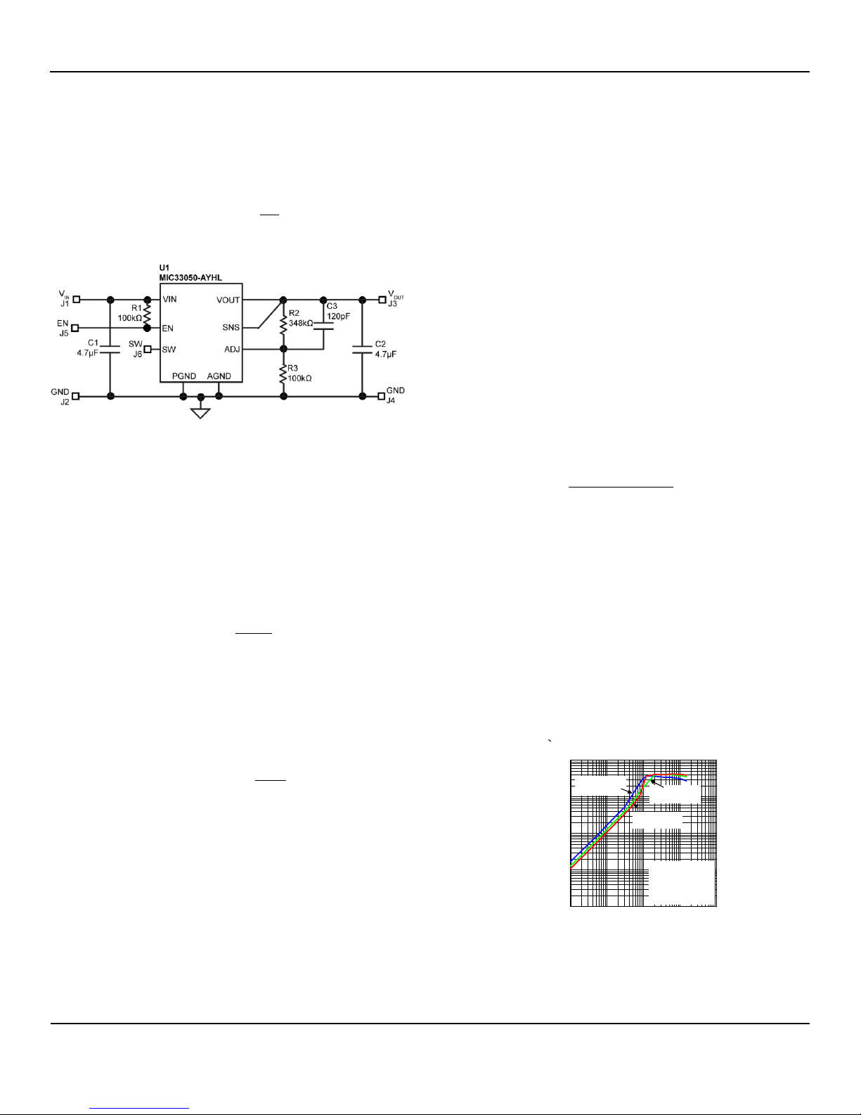
The output voltage of the MIC33050-AYHL is set by the
feedback resistors R2 and R3. Follow the equation and
circuit below to determine V
OUT
:
Eq. 1
This increases the output voltage. If the output voltage is
over the regulation threshold, then the error comparator
turns the PMOS off for a minimum-off-time until the
output drops below the threshold. The NMOS acts as an
ideal rectifier that conducts when the PMOS is off. Using
a NMOS switch instead of a diode allows for lower
voltage drop across the switching device when it is on.
The asynchronous switching combination between the
PMOS and the NMOS allows the control loop to work in
discontinuous mode for light load operations. In
discontinuous mode, the MIC33050 works in pulse
frequency modulation (PFM) to regulate the output. As
the output current increases, the off-time decreases,
thus provides more energy to the output. This switching
scheme improves the efficiency of MIC33050 during light
load currents by only switching when it is needed. As the
load current increases, the MIC33050 goes into
continuous conduction mode (CCM) and switches at a
frequency centered at 4MHz. The equation to calculate
the load when the MIC33050 goes into continuous
conduction mode may be approximated by the following
formula:
Figure 1. Typical Circuit for MIC33050-AYHL (V
= 1.8V)
OUT
The default output voltage for the evaluation board is set
to 1.8V (R2=348kΩ, R3=100kΩ). A different output
voltage can be obtained by removing R2 and replacing it
with the desired resistance. The equation below can be
used to find R2:
Eq. 2
Changing the output voltage to 2.5V, assuming
R3=100kΩ, can be accomplished via the equation
below:
Eq. 3
The result is 523kΩ for R2 which gives an output voltage
of 2.5V.
Eq. 4
As shown in the previous equation, the load at which
MIC33050 transitions from HyperLight Load mode to
PWM mode is a function of the input voltage (VIN), output
voltage (V
), duty cycle (D), inductance (L) and
OUT
frequency (f). As shown in Figure 1, as the Output
Current increases, the switching frequency also
increases until the MIC33050 goes from HyperLight
Load mode to PWM mode at approximately 120mA. The
MIC33050 will switch at a relatively constant frequency
around 4MHz once the output current is over 120mA.
HyperLight Load Mode
MIC33050 uses a minimum on and off time proprietary
control loop (patented by Micrel). When the output
voltage falls below the regulation threshold, the error
comparator begins a switching cycle that turns the
PMOS on and keeps it on for the duration of the
minimum-on-time.
Figure 2. SW Frequency vs. Output Current
Page 3
Micrel, Inc.
MIC33050 Evaluation Board
March 24, 2014
3
Revision 4.0
Item
Part Number
Manufacturer
Description
Qty.
C1, C2
C1608X5R0J475K
TDK
(1)
4.7µF Ceramic Capacitor, 6.3V, X5R, Size 0603
2
C3
C1608C0G1H561J
TDK
560pF Ceramic Capacitor, 50V, NPO, Size 0603
1
R1
CRCW0603100KFKEA
Vishay
(2)
100kΩ, Tolerance 1%, Size 0603
1
U1
MIC33050-xYHL
Micrel, Inc.
(3)
4MHz Internal Inductor PWM Buck Regulator with
HyperLight Load Mode
1
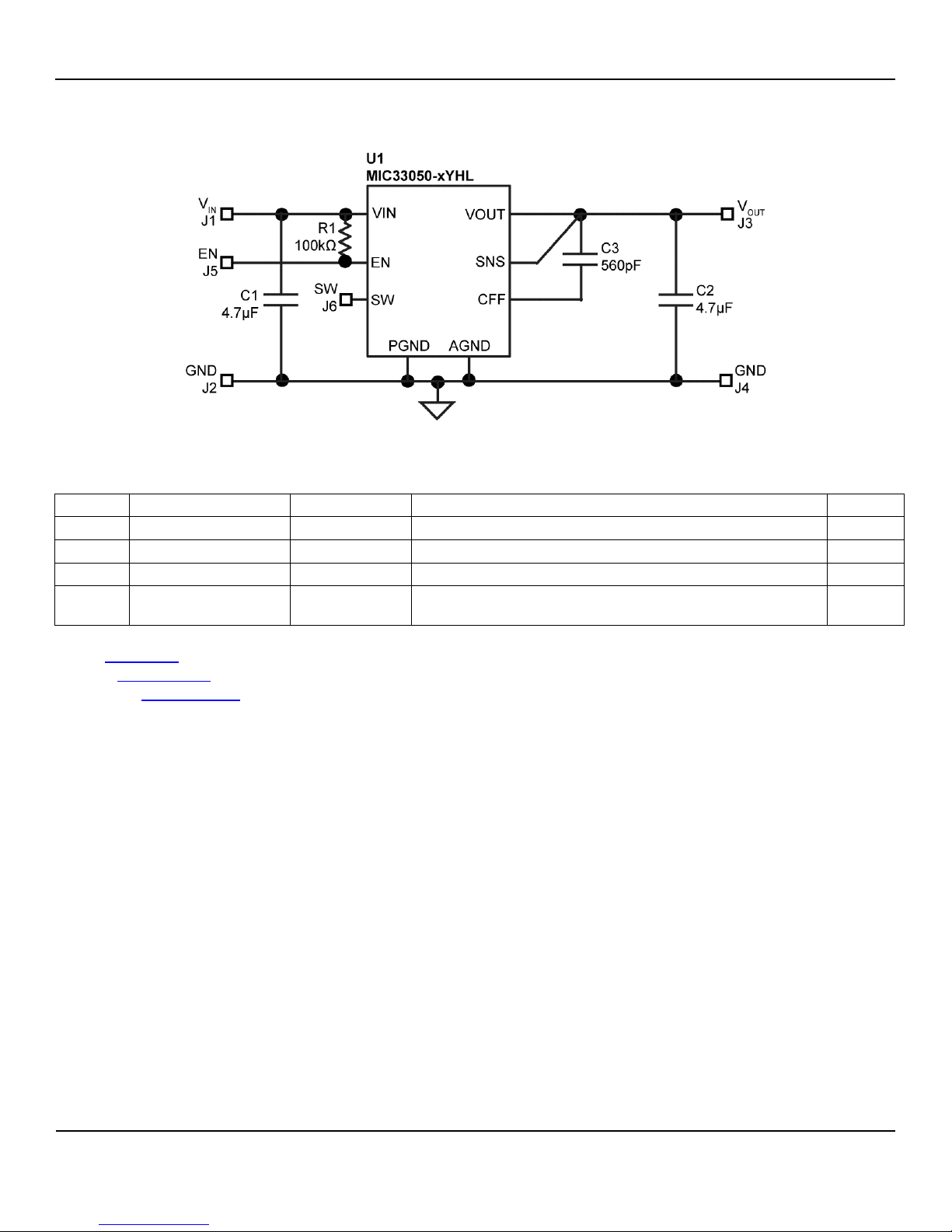
MIC33050 Typical Circuit (Fixed)
Bill of Materials
Notes:
1. TDK: www.tdk.com.
2. Vishay: www.vishay.com.
3. Micrel, Inc: www.micrel.com.
Page 4
Micrel, Inc.
MIC33050 Evaluation Board
March 24, 2014
4
Revision 4.0
Item
Part Number
Manufacturer
Description
Qty.
C1, C2
C1608X5R0J475K
TDK
(1)
4.7µF Ceramic Capacitor, 6.3V, X5R, Size 0603
2
C3
C1608C0G1H121J
TDK
120pF Ceramic Capacitor, 50V, NPO, Size 0603
1
R1, R3
CRCW0603100KFKEA
Vishay
(2)
100kΩ, Tolerance 1%, Size 0603
2
R2
CRCW0603348KFKEA
Vishay
348kΩ, Tolerance 1%, Size 0603
1
U1
MIC33050-AYHL
Micrel, Inc.
(3)
4MHz Internal Inductor PWM Buck Regulator with
HyperLight Load Mode
1
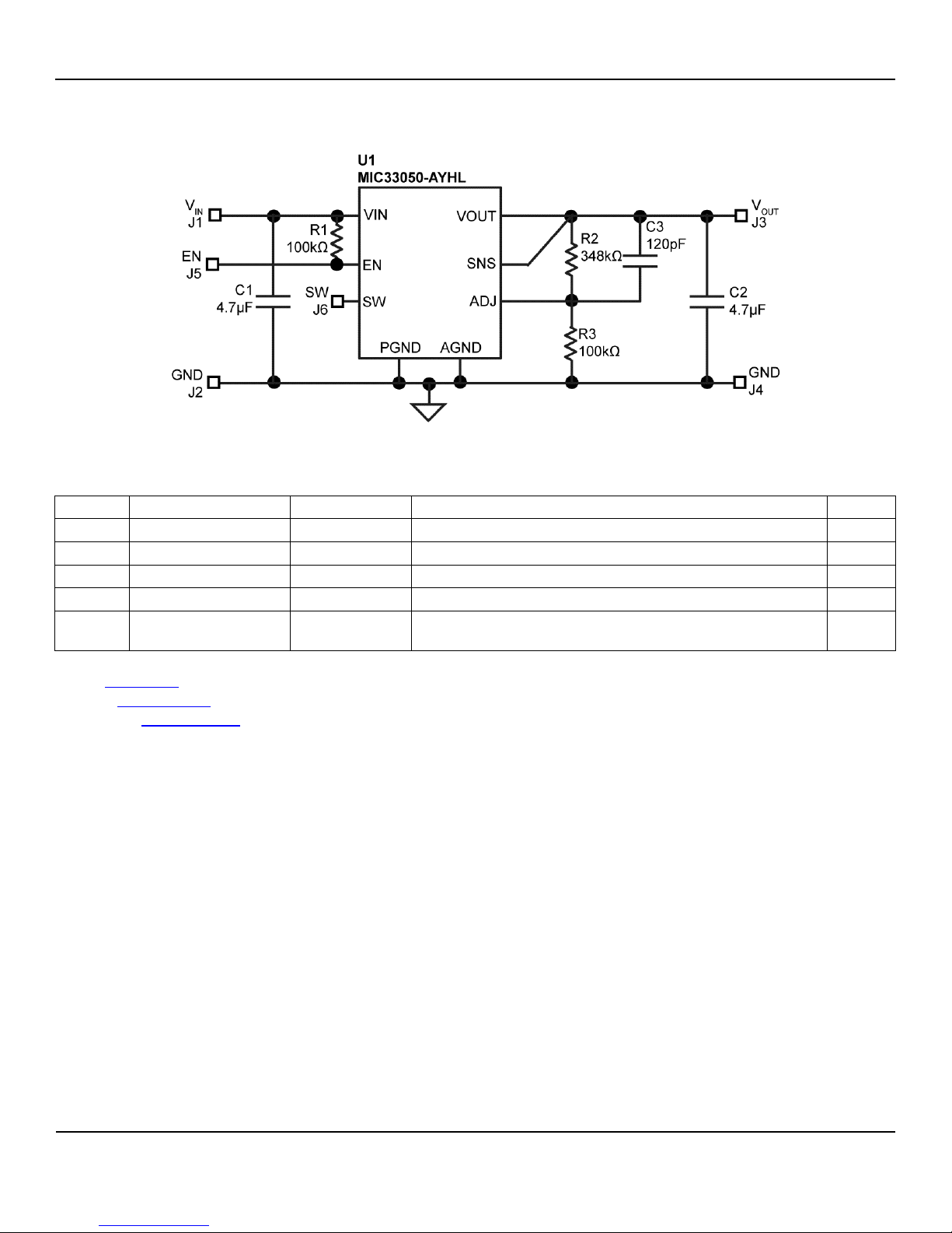
MIC33050 Typical Circuit (Adjustable)
Bill of Materials
Notes:
1. TDK: www.tdk.com.
2. Vishay: www.vishay.com.
3. Micrel, Inc: www.micrel.com.
Page 5
Micrel, Inc.
MIC33050 Evaluation Board
March 24, 2014
5
Revision 4.0
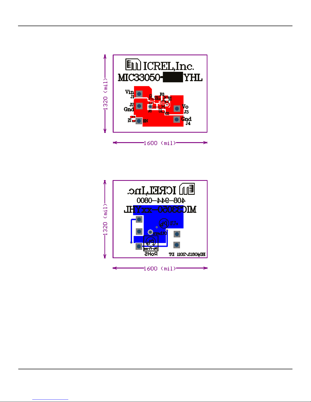
PCB Layout Recommendations
Top Layer
Bottom Layer
Page 6

Micrel, Inc.
MIC33050 Evaluation Board
March 24, 2014
6
Revision 4.0
MICREL, INC. 2180 FORTUNE DRIVE SAN JOSE, CA 95131 USA
TEL +1 (408) 944-0800 FAX +1 (408) 474-1000 WEB http://www.micrel.com
Micrel makes no representations or warranties with respect to the accuracy or completeness of the information furnished in this data sheet. This
information is not intended as a warranty and Micrel does not assume responsibility for its use. Micrel reserves the right to change circuitry,
specifications and descriptions at any time without notice. No license, whether express, implied, arising by estoppel or otherwise, to any intellectual
property rights is granted by this document. Except as provided in Micrel’s terms and conditions of sale for such products, Micrel assumes no liability
whatsoever, and Micrel disclaims any express or implied warranty relating to the sale and/or use of Micrel products including liability or warranties
relating to fitness for a particular purpose, merchantability, or infringement of any patent, copyright or other intellectual property right.
Micrel Products are not designed or authorized for use as components in life support appliances, devices or systems where malfunction of a product
can reasonably be expected to result in personal injury. Life support devices or systems are devices or systems that (a) are intended for surgical implant
into the body or (b) support or sustain life, and whose failure to perform can be reasonably expected to result in a significant injury to the user. A
Purchaser’s use or sale of Micrel Products for use in life support appliances, devices or systems is a Purchaser’s own risk and Purchaser agrees to fully
indemnify Micrel for any damages resulting from such use or sale.
© 2014 Micrel, Incorporated.
 Loading...