

MICREL MIC2777-XXBM5 Datasheet
MIC2777 Micrel
MIC2777
Dual Micro-Power Low Voltage Supervisor
Advance Information
General Description
The MIC2777 is a dual power supply supervisor that provides
under-voltage monitoring, manual reset capability, and poweron reset generation in a compact 5-pin SOT package. Features include two under-voltage detectors, one fixed and one
adjustable, and both active-high and active-low reset outputs. One under-voltage detector compares VDD against a
fixed threshold. Ten factory-programmed thresholds are available. The other under-voltage detector is user-adjustable.
The reset outputs are asserted for no less than 140ms at
power-on and any time VDD or the input voltage drops below
the corresponding reference voltage. They remain asserted
for the timeout period after the input voltage and V
quently rise back above the threshold boundaries. A reset
can be generated at any time by pulling down on the adjustable input. Hysteresis is included to prevent chattering due to
noise. Typical supply current is a low 3.5µA.
DD
subse-
Features
• Monitors two independent power supplies for undervoltage conditions
• One fixed and one user adjustable input
• 1.5% theshold accuracy
• Choice of factory-programmed thresholds
• User-adjustable input can monitor supplies as low as
0.3V
• Generates 140ms (minimum) power-on RESET pulse
• Manual reset capability
• Both active-high and active-low RESET outputs
• Input may be pulled above VDD (abs. max.)
• /RST output valid down to 1.2V
• Ultra-low supply current, 3.5µA typical
• Rejects brief input transients
• IttyBitty™ 5-lead SOT-23 package
Applications
• Monitoring processor, ASIC, or FPGA core and I/O
voltages
• Computer systems
• PDAs, hand-held PCs
• Embedded controllers
• Telecommunications systems
• Power supplies
• Wireless / Cellular systems
• Networking hardware
Ordering Information
Part Number Marking Junction Temp. Range Package
MIC2777-XXBM5 UNXX –40°C to +85°C SOT-23-5
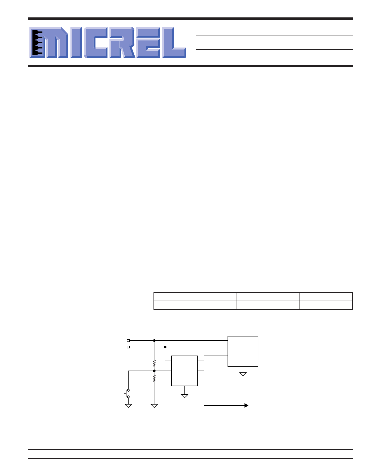
Typical Application
V
1.0V
CORE
V
I/O
1.8V
Manual
Reset
MIC2777
/RST
VDD
R1
IN
RST
R2
GND
Typical Application
IttyBitty™ is a trademark of Micrel, Inc.
Micrel, Inc. • 1849 Fortune Drive • San Jose, CA 95131 • USA • tel + 1 (408) 944-0800 • fax + 1 (408) 944-0970 • http://www.micrel.com
September 29, 2000 1 MIC2777
MICROPROCESSOR
V
CORE
V
I/O
/RESET
GND
OTHER
LOGIC

MIC2777 Micrel
Standard Voltage Options*
Voltage Typical Nominal Threshold
Code Application (VDD) Voltage (VTH)
46 5.0V ±5% 4.68
44 5.0V ±10% 4.43
31 3.3V ±5% 3.09
29 3.3V ±10% 2.93
28 3.0V ±5% 2.81
26 2.85V ±5% 2.67
25 2.70V ±5% 2.53
23 2.5V ±5% 2.34
22 2.4V ±5% 2.25
17 1.8V ±5% 1.69
*There are ten standard versions available with an order increment of 3000 pieces. Samples of standard versions are
normally available from stock. Contact factory for information on non-standard versions. Available in tape-and-reel only.
Pin Configuration
Pin Description
Pin Number Pin Name Pin Function
1 /RST Digital (Output): Asserted low whenever V
2 GND Ground
3 RST Digital (Output): Asserted high whenever V
4 IN Analog (Input): The voltage on this pin is compared to the internal 300mV
5 VDD Analog (Input): Power supply input for internal circuitry and input to the fixed
GND
2
/RST
13
VDDIN
RST
45
SOT-23-5 (M5)
or VDD falls below the reference
voltage. It will remain asserted for no less than 140ms after V
IN
return above the threshold limits.
or VDD falls below the refer-
IN
ence voltage. It will remain asserted for no less than 140ms after V
VDD return within above the threshold limit.
reference. An undervoltage condition will trigger a reset sequence. Manual
reset capability can be achieved by adding a switch between this pin and
ground.
voltage monitor: The votage on this pin is compared against the internal
voltage reference. An undervoltage condition will trigger a reset sequence.
and V
IN
IN
DD
and
MIC2777 2 September 29, 2000
MIC2777 Micrel
Absolute Maximum Ratings (Note 1)
Supply Voltage (V
Input Voltage (V
RST, (/RST) Current .................................................. 20mA
Storage Temperature (T
ESD Rating, Note 3 ................................................... 1.5kV
) ..................................... –0.3V to +7V
DD
) ......................................... –0.3V to +7V
IN
) ....................... –65°C to +150°C
S
Operating Ratings (Note 2)
Supply Voltage (V
Input Voltage
(VIN) ........................................................... –0.3V to +6.0V
Ambient Temperature Range (TA) ............. –40°C to +85°C
Package Thermal Resistance (θ
) .................................. +1.5V to +5.5V
DD
) ...................... 256°C/W
JA
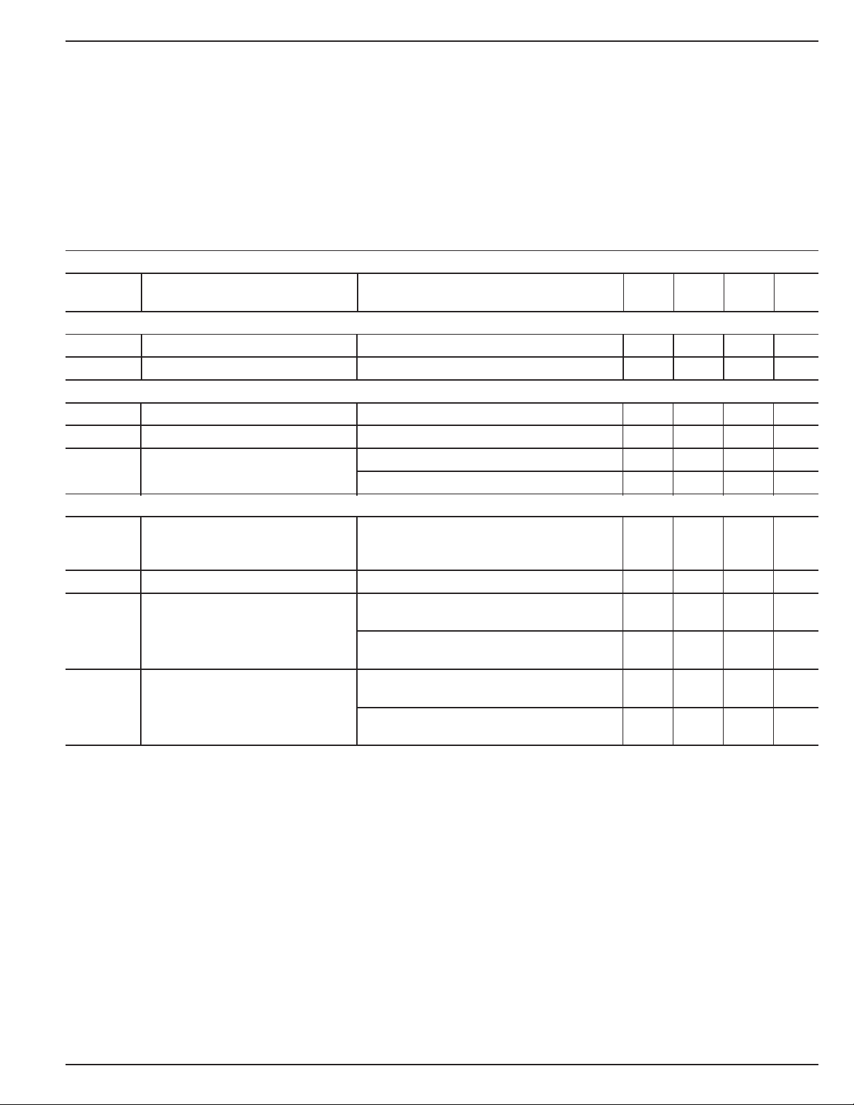
Electrical Characteristics
Note 5; TA = +25°C, bold values indicate –40°C ≤ TA ≤ +85°C; unless noted
Symbol Parameter Condition Min Typ Max Units
I
DD
Supply Current VDD = V
VDD VOLTAGE THRESHOLD
Under-Voltage Threshold On V
V
HYST
Hysteresis Voltage 1%
IN, UNDER-VOLTAGE DECTECTOR INPUT
V
V
I
IN
REF
HYST
Under-Voltage Threshold 295 300 305 mV
Hysteresis Voltage 3mV
Input Current 5pA
RST, /RST OUTPUTS
t
PROP
t
RST
V
OL
V
OH
Propagation Delay VIN = (V
Reset Pulse Width 140 280 ms
RST or /RST Output Voltage Low I
RST or /RST Output Voltage High I
DD
Note 5; /MR, RST, /RST open
IN
VTH-1.5%
T
≤ TA ≤ T
MIN
V
= (V
IN
VDD = (VTH + 2.5%) to (VTH – 2.5%), VIN =V
= 1.6mA; 0.3 V
SINK
VDD ≥ 1.6V
I
= 100µA; 0.3 V
SINK
MAX
REF(MAX)
REF(MIN)
+ 100mV) to 20 µs
– 100mV) or
DD
VDD ≥ 1.2V, Note 4
SOURCE
= 500µA; 0.8V
VDD ≥ 1.5V
RST asserted, I
SOURCE
= 10µA; 0.8V
VDD ≥ 1.2V, Note 4
3.5 µA
V
THVTH
DD
DD
+1.5%
V
10 nA
V
V
Note 1. Exceeding the absolute maximum rating may damage the device.
Note 2. The device is not guaranteed to function outside its operating rating.
Note 3. Devices are ESD sensitive. Handling precautions recommended. Human body model, 1.5k in series with 100pF.
Note 4. VDD operating range is 1.5V to 5.5V. Output is guaranteed to be asserted down to VDD = 1.2V.
Note 5. VDD equals the nominal “Typical Application (VDD)” as shown in “Standard Voltage Options Table.”
September 29, 2000 3 MIC2777
 Loading...