

MICREL MIC2514BM5 Datasheet
MIC2514 Micrel
MIC2514
IttyBitty™ Integrated High-Side Switch
Preliminary Information
General Description
The MIC2514 is an integrated high-side power switch that
consists of a TTL compatible input and protected
P-channel MOSFET. The MIC2514 can be used instead of
a separate high-side driver and MOSFET in many lowvoltage applications.
The MIC2514 switches voltage ranging from 3V to 13.5V and
delivers more than 400mA continuous current. A slow turnon feature prevents high inrush current when switching
capacitive loads. The internal control circuitry is powered
Features
• MOSFET on-resistance
1.5Ω typical at 5V
0.95Ω typical at 12V
• 3V to 13.5V input
•25µA typical on-state supply current at 5V
•<1µA typical off-state supply current at 5V
• Current limit
• Thermal shutdown
• Slow turn-on
from the unswitched 3V to 13.5V input.
Current limiting is internally fixed at approximately 1.9A and
requires no external components.
Applications
• 3.3V to 13.5V power management
Thermal shutdown turns off the output if the die temperature
exceeds approximately 170°C.
Ordering Information
The MIC2514 is available in the 5-lead SOT-23-5 package
with a temperature range of –40°C to +85°C.
Part Number Temperature Range Package
MIC2514BM5 –40°C to +85°C SOT-23-5
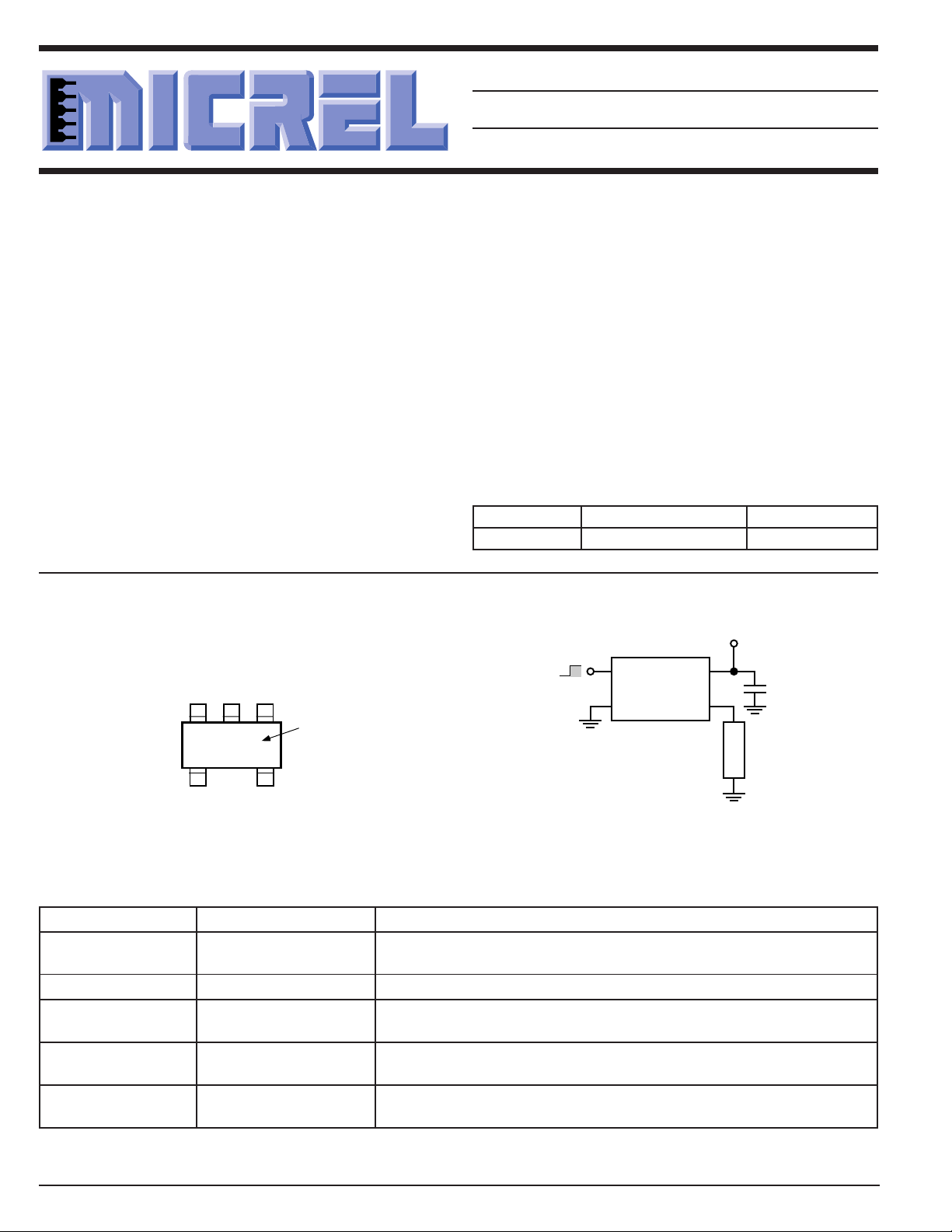
Pin Configuration Typical Application
MIC2514
13
CTL
2
GND
GND
2
F10
CTL
13
Part
Identification
NCOUT
IN
45
On
Off
3V to 13.5V
IN
4
OUT
0.1µF
Load
5-Lead SOT-23-5 (M5)
Pin Description
Pin Number Pin Name Pin Function
1 CTL Control (Input): Noninverting TTL compatible control input.
2 GND Ground
3 IN Supply Input: Output MOSFET source. Also supplies IC’s internal circuitry.
4 OUT Switch Output: Output MOSFET drain. Connect to switched side
5 NC Not internally connected. Connect to ground plane for lowest package
High-Side Power Switch
High = on, low = off.
Connect to supply.
of load.
thermal resistance.
6-18 1997
MIC2514 Micrel
Absolute Maximum Ratings
Supply Voltage (VIN) ...................................................+20V
Output Current (I
Control Input (V
Storage Temperature (TA) ....................... –65°C to +150°C
)...............................Internally Limited
OUT
) ....................................... –0.3V to 15V
CTL
Operating Ratings
Supply Voltage (VIN) .................................... +3V to +13.5V
Ambient Operating Temperature (TA) ........ –40°C to +85°C
Thermal Resistance
(θJA)...................................................................220°C/W
(θJC) ..................................................................130°C/W
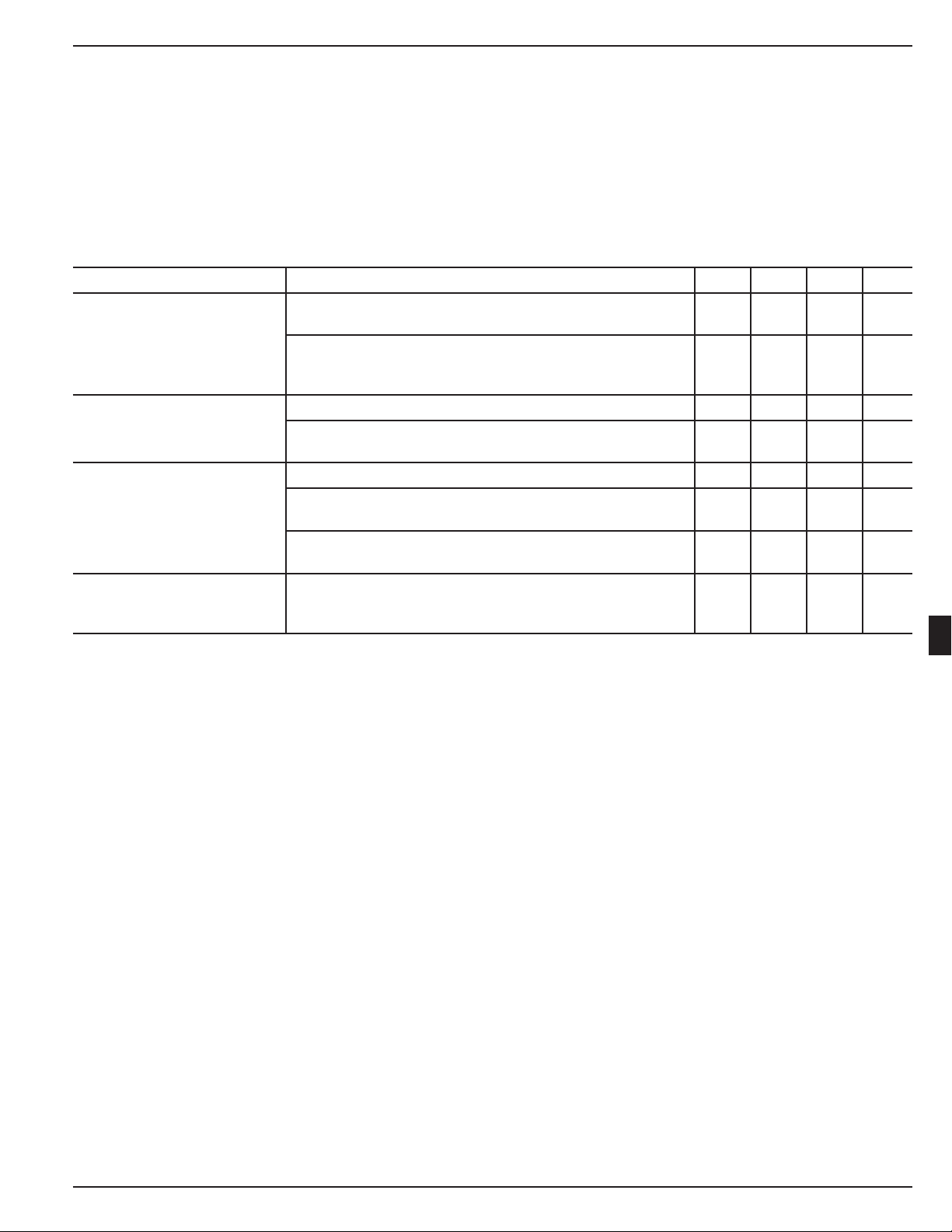
Electrical Characteristics
VIN = +5V; TA = 25°C, except bold values indicate –40°C ≤ TA ≤ 85°C, Note 1; unless noted.
Parameter Condition Min Typ Max Units
Supply Current V
Control Input Voltage V
Output MOSFET Resistance VIN = 3V 2.4 4.5 Ω
Current Limit Threshold V
General Note: Devices are ESD protected, however, handling precautions recommended.
Note 1: Devices production tested at 25°C, but Devices guaranteed over indicated temperature range.
= logic 0, VIN = 5V 0.6 10 µA
CTL
V
= logic 0, VIN = 13.5V 2.0 25 µA
CTL
= logic 1, VIN = 3V 10 20 µA
V
CTL
V
= logic 1, VIN = 5V 25 40 µA
CTL
V
= logic 1, VIN = 13.5V 95 200 µA
CTL
= logic 0, 3V ≤ VIN ≤ 13.5V 0 0.8 V
CTL
= logic 1, 3V ≤ VIN ≤ 5V 0.8 1.45 2.0 V
V
CTL
V
= logic 1, 5V ≤ VIN ≤ 13.5V 0.8 1.65 2.3 V
CTL
V
= 5V 1.5 2.4 Ω
IN
= 12V .95 1.5 Ω
V
IN
= 3V 0.5 1.5 A
IN
V
= 5V 1.0 1.4 2.0 A
IN
VIN = 12V 1.2 1.9 2.5 A
2.7 Ω
1.7 Ω
6
1997 6-19
 Loading...