

Micrel MIC23030, MIC23030-AYMT EV, MIC23030-CYMT EV, MIC23030-4YMT EV, MIC23030-FYMT EV User Manual
...Page 1
General Description
The MIC23030 is a 400mA 8MHz switching regulator
featuring HyperLight Load™ mode. The MIC23030 is
highly efficient throughout the entire output current range,
drawing just 21µA of quiescent current in operation. The
tiny 1.6 x 1.6mm MLF
8MHz switching frequency, enables a compact sub-1mm
height solution with only three external components. The
MIC23030 provides accurate output voltage regulation
under the most demanding conditions and responds
extremely quickly to a load transient with exceptionally
small output voltage ripple.
Factoring in the output current, the internal circuitry of the
MIC23030 automatically selects between two modes of
operation for optimum efficiency. Under light load
conditions, the MIC23030 goes into HyperLight Load™
mode. HyperLight Load™ uses a Pulse-Frequency
Modulation (PFM) control scheme that controls the off time
at light load. This proprietary architecture reduces the
amount of switching needed at light loads, thereby
increasing operating efficiency. The MIC23030 attains up
to 83% efficiency at 1mA output load. As the load current
increases beyond approximately 100mA, the device
operates using the Pulse-Width Modulation (PWM) method
for up to 91% efficiency at higher loads. The two modes of
operation ensure the highest efficiency across the entire
load range.
The MIC23030 operates from an input voltage range of
2.7V to 5.5V and features internal power MOSFETs that
deliver up to 400mA of output current. This step-down
regulator provides an output voltage accuracy of +/-2.5%
across the junction temperature range of -40ºC to +125ºC.
The MIC23030 is available in fixed or adjustable versions
supporting an output voltage as low as 0.7V.
Requirements
The MIC23030 evaluation board requires an input power
source that is able to deliver greater than 500mA at 2.7V
to the MIC23030. The output load can either be an active
(electronic) or passive (resistive) load.
®
package, in combination with the
MIC23030 Evaluation Board
8MHz PWM 400mA Buck Regulator
with HyperLight Load™
Getting Started
1. Connect an external supply to the V
terminal. Apply the desired input voltage to V
(J1) and ground (J2) terminals of the evaluation
board, paying careful attention to polarity and
supply voltage (2.7V ≤ V
may be placed between the input supply and the
(J1) terminal. Be sure to monitor the supply
V
IN
voltage at the V
and/or power lead resistance can reduce the
voltage supplied to the device.
2. Connect a load to the V
terminal (J4). The load can be either passive
(resistive) or active (electronic load). An ammeter
may be placed between the load and the output
terminal. Ensure the output voltage is monitored at
the V
(J3) terminal.
OUT
3. Enable the MIC23030. The MIC23030 evaluation
board has a pull-up resistor to V
device, apply a voltage below 0.5V to the EN (J5)
terminal or place a jumper on JP1 to ground the
enable. In the absence of the pull-up resistor, the
device is enabled by applying a voltage greater
than 1.2V to the EN (J5) terminal. The enable pin
must be either pulled high or low for proper
operation. Removing the pull-up resistor and
leaving the pin floating will cause the regulator to
operate in an indeterminable state.
Output Voltage
The MIC23030 evaluation board is available with the
following output voltage options listed below:
Ordering Information
Part Number Description
MIC23030-AYMT EV Adjustable Output Evaluation Board
MIC23030-CYMT EV 1.0V Fixed Output Evaluation Board
MIC23030-4YMT EV 1.2V Fixed Output Evaluation Board
MIC23030-FYMT EV 1.5V Fixed Output Evaluation Board
MIC23030-GYMT EV 1.8V Fixed Output Evaluation Board
Note: Other voltage options available on request
(J1)
IN
≤ 5.5V). An ammeter
IN
(J1) terminal, since the ammeter
IN
(J3) and ground
OUT
. To disable the
IN
IN
HyperLight Load is a trademark of Micrel, Inc. MLF is a registered trademark of Amkor Technology.
Micrel Inc. • 2180 Fortune Drive • San Jose, CA 95131 • USA • tel +1 (
August 2008
408) 944-0800 • fax + 1 (408) 474-1000 • http://www.micrel.com
M9999-072208-A
Page 2
Micrel, Inc. MIC23030 Evaluation Board
Output Voltage (Adjustable Option Only)
The output voltage of the MIC23030-AYMT regulator is
determined by feedback resistors R1 and R2 whose
values are calculated as follows:
R1
R2
+×= 1
⎞
⎟
⎠
OUT
0.62VV
⎛
⎜
⎝
continuous conduction mode (CCM) and switches at a
frequency centered at 8MHz. The equation to calculate the
load where the MIC23030 goes into continuous conduction
mode is approximated by the following formula:
×−
DVV
)(
I
LOAD
⎛
⎜
>
⎜
⎝
OUTIN
×
fL
2
⎞
⎟
⎟
⎠
As shown in the previous equation, the load at which
MIC23030 transitions from HyperLight Load™ mode to
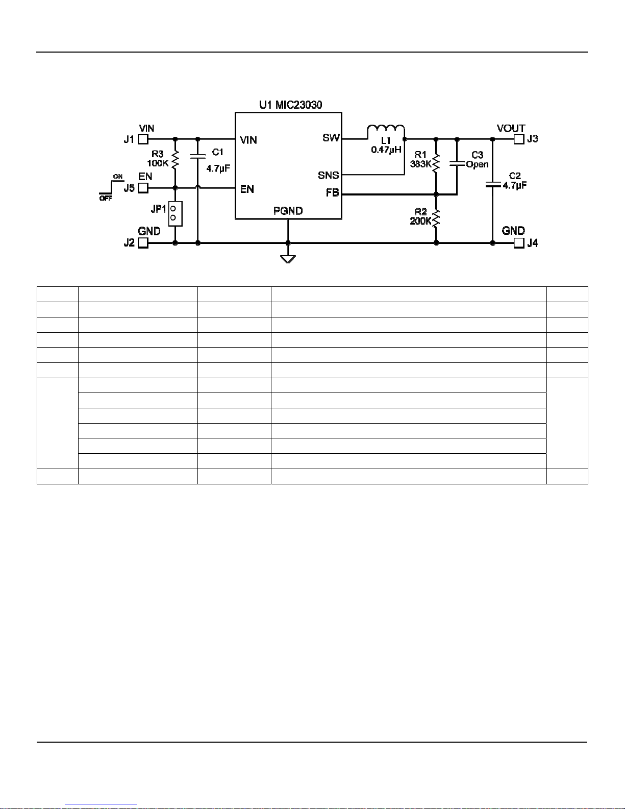
The output on the evaluation board is by default set to
1.8V (R1=383kΩ, R2=200kΩ), but can easily be modified
by removing R1 and replacing it with the value that yields
the desired output voltage.
PWM mode is a function of the input voltage (V
voltage (V
), duty cycle (D), inductance (L) and
OUT
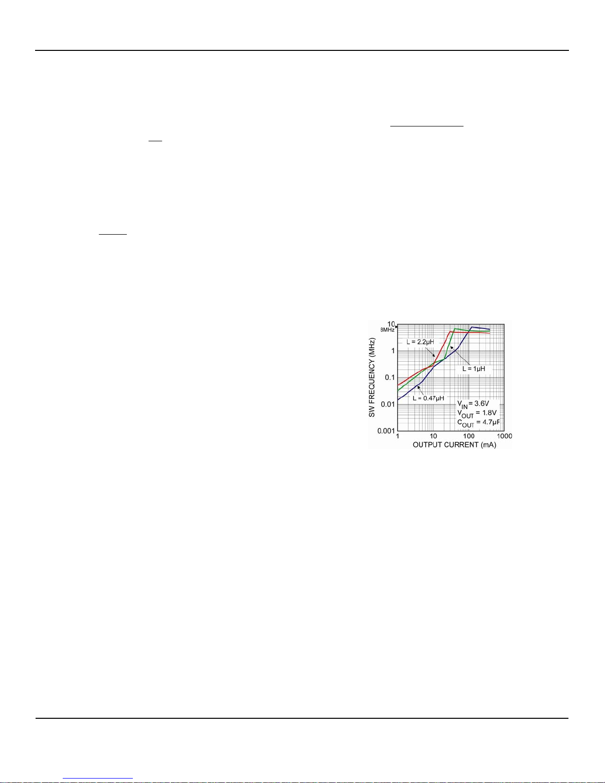
frequency (f). This is illustrated in the graph below.
Suitable inductors for the MIC23030 range from 0.47µH to
), output
IN
2.2µH. The device may be tailored to enter HyperLight
V
⎛
⎜
⎜
0.62V
⎝
OUT
R1
For optimum transient response performance, R2 should
be in the range of 180k
HyperLight Load™ Mode
MIC23030 uses a patented minimum on and off time
⎞
−=
R21
×
⎟
⎟
⎠
Ω to 220kΩ.
Load™ mode or PWM mode at a specific load current by
selecting the appropriate inductor. For example, if a 2.2µH
inductor is selected in a 3.6V
to 1.8V
IN
application, the
OUT
MIC23030 will transition into PWM mode at a load of
approximately 30mA. If under the same condition a 0.47µH
inductor is chosen, the MIC23030 will transition into PWM
mode at approximately 120mA.
control loop at light loads. When the output voltage falls
below the lower regulation threshold, the error comparator
begins a switching cycle that turns the PMOS on and
keeps it on for the duration of the minimum-on-time. This
increases the output voltage. Once the output voltage rises
to the higher regulation threshold, the error comparator
turns the PMOS off for a minimum off time until the output
drops down to the lower threshold. The NMOS acts as an
ideal rectifier that conducts when the PMOS is off. Using a
NMOS switch instead of a diode, reduces power
dissipation as the current is sourced from ground. In
discontinuous mode, the MIC23030 works in pulse
frequency modulation (PFM) to regulate the output. As the
output current increases, the off-time decreases, more
energy is delivered to the output. This switching scheme
SW Frequency vs. Inductance
improves the efficiency of MIC23030 during light load
currents by activating the power FETs only as needed. As
the load current increases, the MIC23030 goes into
August 2008 2
M9999-072208-A
Page 3
Micrel, Inc. MIC23030 Evaluation Board
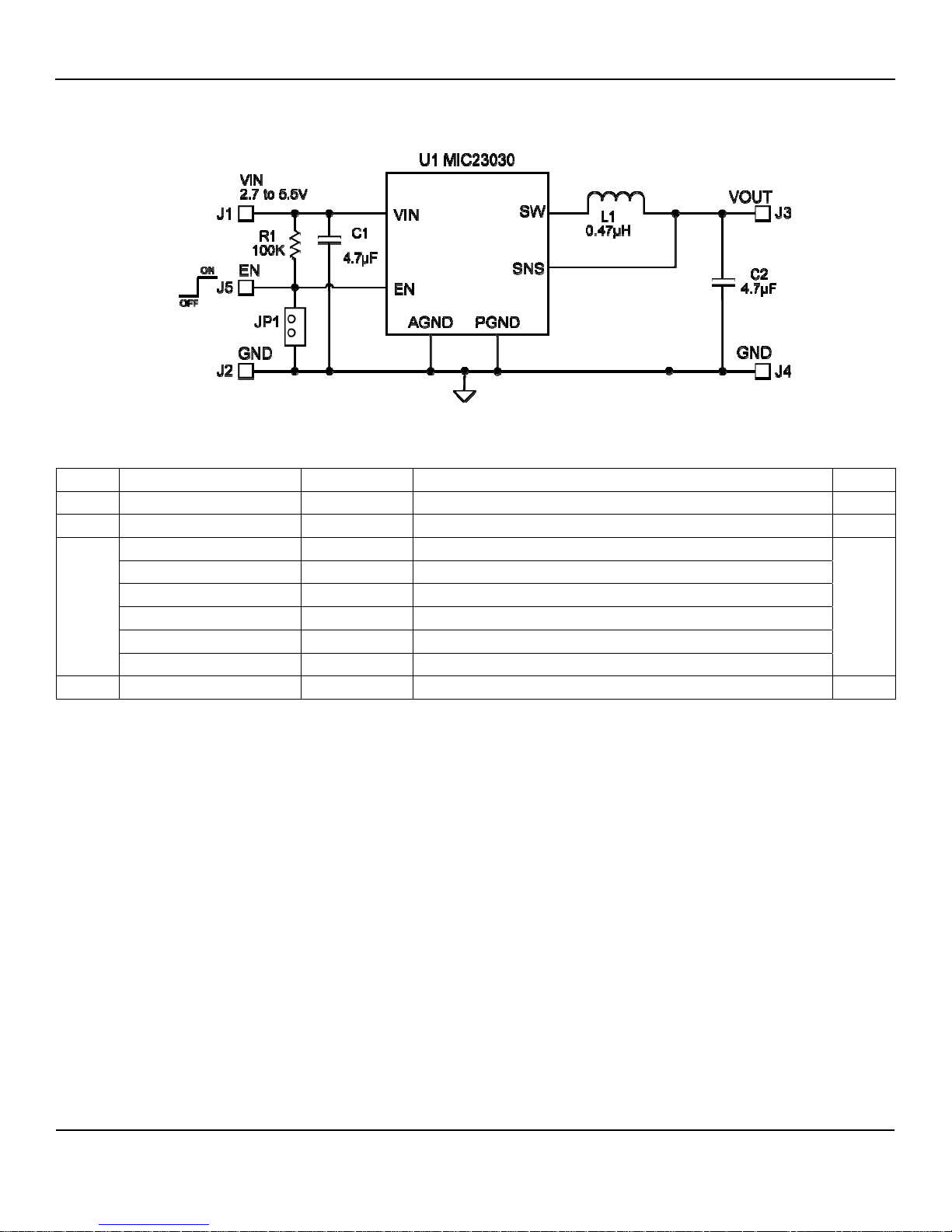
MIC23030 Typical Application Circuit (Fixed)
Bill of Materials
Item Part Number Manufacturer Description Qty.
C1, C2 C1608X5R0J475K TDK
R1 CRCW06031003FT1 Vishay
LQM21PNR47M00 Murata
LQH32CNR47M33 Murata
L1
LQM31PNR47M00 Murata
GLF251812T1R0M TDK
MIPF2520D1R5 FDK
EPL2010-471 Coilcraft
U1 MIC23030-xYMT Micrel, Inc.
Notes:
1. TDK: www.tdk.com
2. Vishay: www.vishay.com
3. Murata: www.murata.com
4. FDK: www.fdk.co.jp
5. Coilcraft: www.coilcraft.com
Micrel, Inc.: www.micrel.com
6.
(1)
4.7µF Ceramic Capacitor, 6.3V, X5R, Size 0603 2
(2)
100kΩ, 1%, Size 0603 1
(3)
0.47µH, 0.9A, 90mΩ, L2mm x W1.25mm x H0.5mm
(3)
0.47µH, 1.1A, 42mΩ, L3.2mm x W2.5mm x H2.0mm
(3)
0.47µH, 1.4A, 80mΩ, L3.2mm x W1.6mm x H0.85mm
(1)
1µH, 0.8A, 100mΩ, L2.5mm x W1.8mm x H1.35mm
(4)
1.5µH, 1.5A, 70mΩ, L2.5mm x W2mm x H1.0mm
(5)
0.47µH, 1.6A, 40mΩ, L2.0mm x W1.8mm x H1.0mm
(6)
8MHz 400mA Buck Regulator with HyperLight Load™ Mode 1
1
August 2008 3
M9999-072208-A
Page 4
Micrel, Inc. MIC23030 Evaluation Board
MIC23030 Typical Application Circuit (Adjustable 1.8V)
Bill of Materials
Item Part Number Manufacturer Description Qty.
C1, C2 C1608X5R0J475K TDK
C3 OPEN
R1 CRCW06033833FT1 Vishay
R2 CRCW06032003FT1 Vishay
R3 CRCW06031003FT1 Vishay
LQM21PNR47M00 Murata
LQH32CNR47M33 Murata
L1
LQM31PNR47M00 Murata
GLF251812T1R0M TDK
MIPF2520D1R5 FDK
EPL2010-471 Coilcraft
U1 MIC23030-AYMT Micrel, Inc.
Notes:
1. TDK: www.tdk.com
2. Vishay: www.vishay.com
3. Murata: www.murata.com
4. FDK: www.fdk.co.jp
5. Coilcraft: www.coilcraft.com
Micrel, Inc.: www.micrel.com
6.
(1)
4.7µF Ceramic Capacitor, 6.3V, X5R, Size 0603 2
(2)
383kΩ, 1%, Size 0603 1
(2)
200kΩ, 1%, Size 0603 1
(2)
100kΩ, 1%, Size 0603 1
(3)
0.47µH, 0.9A, 90mΩ, L2mm x W1.25mm x H0.5mm
(3)
0.47µH, 1.1A, 42mΩ, L3.2mm x W2.5mm x H2.0mm
(3)
0.47µH, 1.4A, 80mΩ, L3.2mm x W1.6mm x H0.85mm
(1)
1µH, 0.8A, 100mΩ, L2.5mm x W1.8mm x H1.35mm
(4)
1.5µH, 1.5A, 70mΩ, L2.5mm x W2mm x H1.0mm
(5)
0.47µH, 1.6A, 40mΩ, L2.0mm x W1.8mm x H1.0mm
(6)
8MHz 400mA Buck Regulator with HyperLight Load™ Mode 1
1
August 2008 4
M9999-072208-A
Page 5
Micrel, Inc. MIC23030 Evaluation Board
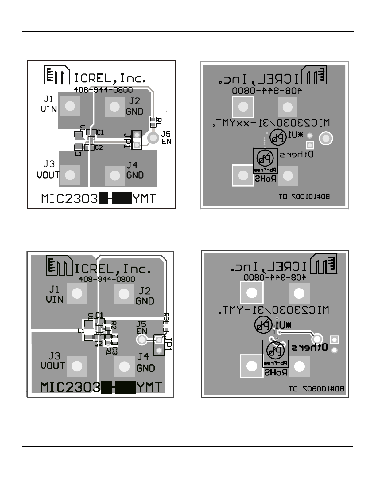
PCB Layout Recommendations
Fixed Top Layer Fixed Bottom Layer
Adjustable Top Layer Adjustable Bottom Layer
August 2008 5
M9999-072208-A
Page 6
Micrel, Inc. MIC23030 Evaluation Board
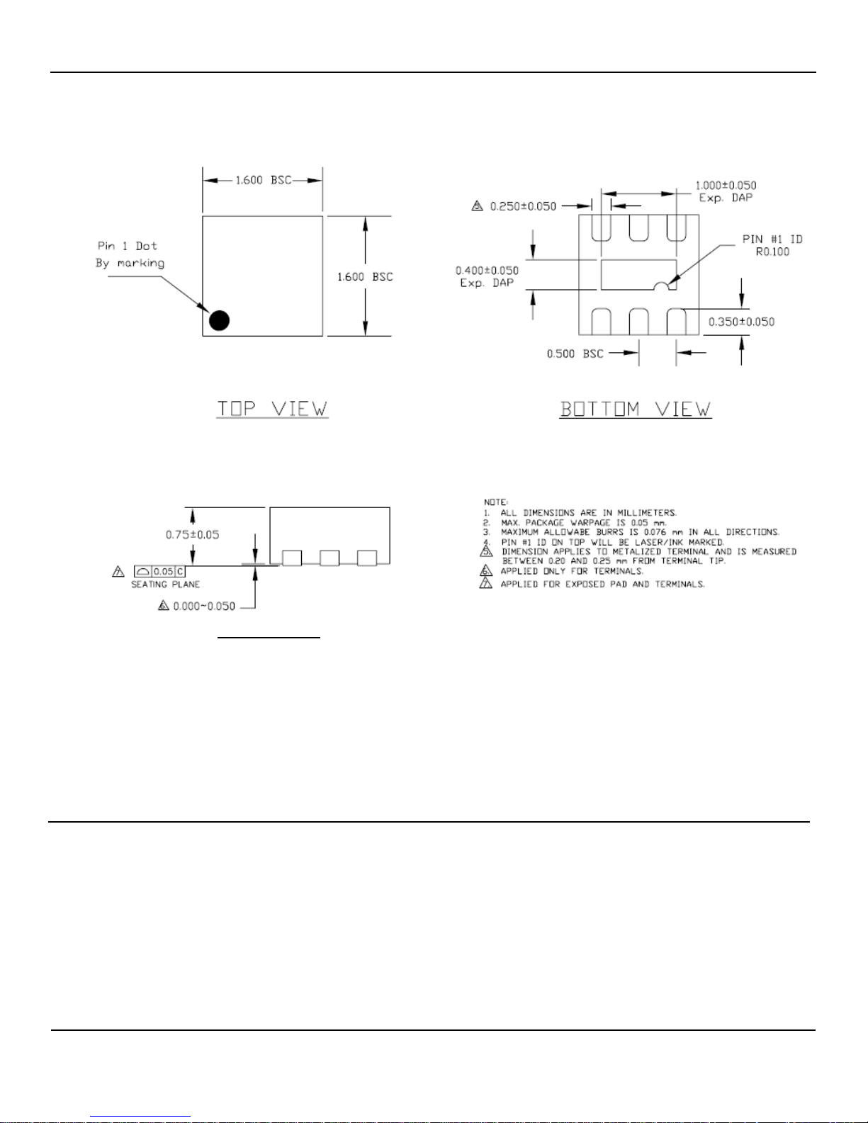
Package Information
SIDE VIEW
6-pin 1.6mm x 1.6mm Thin MLF® (MT)
MICREL, INC. 2180 FORTUNE DRIVE SAN JOSE, CA 95131 USA
TEL +1 (408) 944-0800 FAX +1 (408) 474-1000 WEB http://www.micrel.com
The information furnished by Micrel in this data sheet is believed to be accurate and reliable. However, no responsibility is assumed by Micrel for its
Micrel Products are not designed or authorized for use as components in life support appliances, devices or systems where malfunction of a product
reasonably be expected to result in personal injury. Life support devices or systems are devices or systems that (a) are intended for surgical impla
can nt
into the body or (b) support or sustain life, and whose failure to perform can be reasonably expected to result in a significant injury to the user. A
Purchaser’s use or sale of Micrel Products for use in life support aplpiances, devices or systems is a Purchaser’s own risk and Purchaser agrees to fully
August 2008 6
use. Micrel reserves the right to change circuitry and specifications at any time without notification to the customer.
indemnify Micrel for any damages resulting from such use or sale.
© 2008 Micrel, Incorporated.
M9999-072208-A
 Loading...