

Page 1

General Description
The MIC2169A is a high-efficiency, simple to use 500kHz
PWM synchronous buck control IC housed in a small
MSOP-10 package. The MIC2169A allows compact DC-toDC solutions with a minimal external component count and
cost. The output voltage can be precisely regulated down
to 0.8V. The adaptive all N-Channel MOSFET drive
scheme allows efficiencies over 95% across a wide load
range.
Note: This evaluation board is for 3A applications. A 7A
output evaluation board is also available. The literature for
the 7A evaluation can be found in the MIC2169A data
sheet.
Data sheets and support documentation can be found on
Micrel’s web site at: www.micrel.com.
Requirements
The MIC2169A evaluation board requires an input power
source that is able to deliver greater than 3A at 12V.
Precautions
The evaluation board does not have reverse polarity
protection. Applying a negative voltage to the V
terminal may damage the device.
The MIC2169A evaluation board is tailored for a 5V to 12V
input voltage range. The input voltage range should not
exceed 14.5V on the input.
Getting Started
1. Connect an external supply to the VIN. Apply
desired input voltage to the VIN (J1) and ground
(J2) terminals of the evaluation board, paying
careful attention to polarity and supply voltage
(5VVIN12V). An ammeter may be placed
between the input supply and the VIN terminal to
the evaluation board. Ensure that the supply
voltage is monitored at the VIN terminal. The
ammeter and/or power lead resistance can reduce
the voltage supplied to the input.
2. Enabling the MIC2169A. The MIC2169A is
enabled as soon as a power supply with a voltage
in the range of 3V to 14.5V is connected across
the VIN (J1) and GND (J2) terminals.
(J1)
IN
MIC2169A Evaluation Board
500kHz MSOP-10 Synchronous
Step-Down Controller
Adjusting Output Voltage
The output voltage on the MIC2169A evaluation board is
adjustable. The output voltage is controlled by the
feedback resistors (R1 and R2) and can be calculated as
follows:
2
R
The evaluation board is initially adjusted to 1.5V, but can
easily be modified by removing R3 and replacing it with the
value that yields the desired output voltage. The R2
resistor is recommended for a 3k to 10k resistor range.
Ensure the output voltage selected does not exceed 5V,
since the tantalum output capacitor has a 6.3V voltage
rating. Typically the working voltage for tantalum
capacitors should never exceed 80% of their rated voltage
value. When output voltages greater than 5V are desired,
the output capacitor should be replaced with one where
the output voltage is less than 80% of the output capacitor
voltage rating (tantalum capacitors).
OUT
103
⎛
8.0
VV
⎜
⎝
⎛
⎜
Ω=
kR
⎜
OUT
⎝
Ordering Information
Part Number Description Package
MIC2169AYMM IC 10-Pin MSOP
MIC2169A Tiny3A EV Evaluation Board 10-Pin MSOP
⎞
+= 1
⎟
3
R
⎠
⎞
V
8.0
−
⎟
⎟
VV
8.0
⎠
Micrel Inc. • 2180 Fortune Drive • San Jose, CA 95131 • USA • tel +1 (
May 2007
408
) 944-0800 • fax + 1 (408) 474-1000 • http://www.micrel.com
1
M9999-053107-A
Page 2
Micrel, Inc. MIC2169A Evaluation Board
J1
VIN=5Vto12V
C13
100µF/20V
C11
OPEN
J2
GND
12
+
10µF/16V
1µF/16V
0.1µF
C10
C9
R11
C13
R10
R9
602
5
1
VIN
C8
0.1µF
3
CS
U1
2
VDD
BST
HSD
VSW
C7
10µF/6V
10
9
8
R6
21
R7
D1
SD103BWS
C14
0.1µF/25V
2
MIC2169AYMM
7
4
COMP/EN
1K
LSD
5
FB
GND
6
R8
4
+V
IN
L1
Q1
SI48O4BDY
7
8
1
5
6
3
1 2
R5
C6
1000pF
2.0µH
CDR7D28MN-2R0
C5
CAP
D2
(Open 1N5819HW)
2 1
CAP
RES
C4
C2
330µF
R2
10K
R1
Open
R4
R3
11.3K
C3
Open
C
OUT
TPSD337M006R0045
V
12
+
C1
0.1µF/25V
= AVX
= 1.5V
O
GND
J3
J4
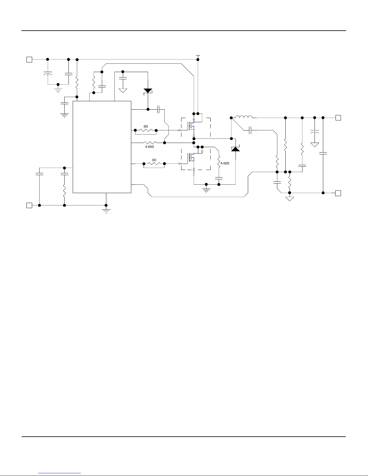
MIC2169A Schematic
May 2007
2
M9999-053107-A
Page 3

Micrel, Inc. MIC2169A Evaluation Board
Bill of Materials
Item Part Number Manufacturer Description Qty.
C1,C8,
C10,C14
C2
C3,C4
C5,C11
C6 VJ0603A102KXXAT Vishay Victramon
C7
C9
C12 C3225X7R1C106M TDK
C13
D1 SD103BWS Vishay
D2 1N5819HW Diodes Inc.
L1 CDR7D28MN-2R0 Sumida
R1,R4 OPEN (0603 size) 2
R2 CRCW06031002FKEY3 Vishay Dale
R3 CRCW06031152FKEY3 Vishay Dale
R5 CRCW06034R02FKEY3 Vishay Dale
R6,R8 OPTIONAL 0, TRACE ON BOARD 2
R7 CRCW06032R00FKEY3 Vishay Dale
R9 CRCW06036020FKEY3 Vishay Dale
R10 CRCW080510R0FKEY3 Vishay Dale
R11 CRCW06031001FKEY3 Vishay Dale
Q1
U1 MIC2169AYMM Micrel, Inc.
Notes:
1. Vishay: www.vishay.com
2. AVX: www.avxcorp.com
3. TDK: www.tdk.com
4. Dioses, Inc.: www.diodes.com
5. Sumida: www.sumida.com
6. Internacional Rectifier: www.irf.com
7. Analog Power: www.analogpowerinc.com
8. Micrel, Inc.: www.micrel.com
TPSD337M006R0045 AVX
TPSD686M020R0100 AVX
VJ0603Y104KXXAT Vishay Victramon
594D337X06R3D2T Vishay/Sprague
(2)
OPEN 4
08056D106MAT2A AVX
C2012X5R0J106M TDK
C2012X7R1C105K TDK
0805YD105MAT2A AVX
594D686X0020D2T Vishay/Sprague
Si4804BDY Vishay/Siliconix
IRF8910 International Rectifier
AM4920N Analog Power
(2)
1
(3)
(3)
1
(2)
(3)
10µF/16V, X7R, Ceramic Capacitor 1
(2)
(1)
Schottky Diode 1
(4)
(5)
2.0µH, 7A Inductor 1
(1)
(1)
(1)
(1)
(1)
(1)
(1)
(8)
(1)
0.1µF/25V, 0603 4
(1)
(1)
1000pF/25V 1
1µF/16V, X7R, 0805, Ceramic Capacitor
(1)
1
330µF, 6.3V, Tantalum
10µF/6.3V, 0805 Ceramic Capacitor
68µF, 20V Tantalum
1
1
1
OPEN 1
10K, 0603, 1/10W, 1% 1
11.5K, 0603, 1/10W, 1% 1
4.02, 0603, 1/10W, 1% 1
2, 0603, 1/10W, 1% 1
602, 0603, 1/10W, 1% 1
10, 0805 ,1/8W, 1% 1
1K, 0603, 1/10W, 1% 1
(1)
1
(6)
1
(7)
Dual Power N-Channel Transistors
1
Step-Down Controller 1
May 2007
3
M9999-053107-A
Page 4
Micrel, Inc. MIC2169A Evaluation Board
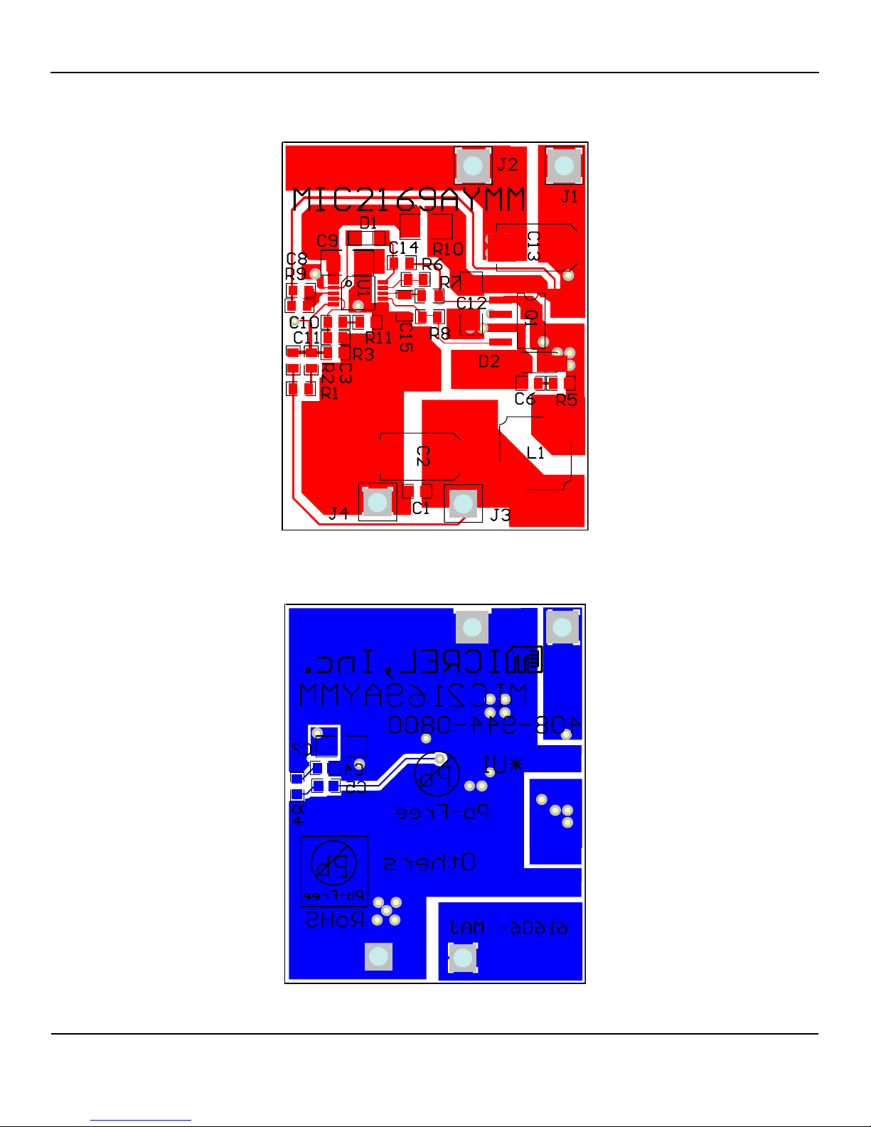
PCB Layout
Top Layer with Silkscreen
May 2007
Bottom Layer with Silkscreen
4
M9999-053107-A
Page 5

Micrel, Inc. MIC2169A Evaluation Board
MICREL, INC. 2180 FORTUNE DRIVE SAN JOSE, CA 95131 USA
TEL +1 (408) 944-0800 FAX +1 (408) 474-1000 WEB http://www.micrel.com
The information furnished by Micrel in this data sheet is believed to be accurate and reliable. However, no responsibility is assumed by Micrel for its
Micrel Products are not designed or authorized for use as components in life support appliances, devices or systems where malfunction of a product
can reasonably be expected to result in personal injury. Life support devices or systems are devices or systems that (a) are intended for surgical implant
into the body or (b) support or sustain life, and whose failure to perform can be reasonably expected to result in a significant injury to the user. A
Purchaser’s use or sale of Micrel Products for use in life support appliances, devices or systems is a Purchaser’s own risk and Purchaser agrees to fully
May 2007
use. Micrel reserves the right to change circuitry and specifications at any time without notification to the customer.
indemnify Micrel for any damages resulting from such use or sale.
© 2007 Micrel, Incorporated.
5
M9999-053107-A
 Loading...