

Page 1

Pollux
MICOS GmbH Version 2.0
Manual
high resolution positioning drive
Page 2

Manual Pollux
Content 2
Contents
Symbols in this documentation...............................................5
Chapter -1- Introduction...................................................................6
Presentation of the controller ........................................................7
Function survey ..............................................................................8
Dimensions Pollux Drive ................................................................9
Dimensions Pollux Box ..................................................................9
Chapter -2- Installation .....................................................................10
Safety notice.....................................................................................11
Declaration by the manufacturer....................................................12
Power supply....................................................................................13
Programming via RS-232 interface ................................................14
Important notices about the RS-232 interface ........................14
RS-232 interface configuration ...............................................14
Motor characteristic adjustments ..................................................15
Commands to adjust the speed torque and holding torque. 15
Speed-Torque characteristic .........................................................16
Pollux-1...................................................................................16
Pollux-2...................................................................................17
Pollux Box with seperated motor ............................................18
Limit switches ..................................................................................19
Limit switch inputs ..................................................................19
Limit switch functions..............................................................19
Switch types ...........................................................................19
Procedure to configure the limit switch inputs ........................20
Limit switch wiring via RJ45 connector...................................21
Safety device (Option) ....................................................................22
Principal function ....................................................................22
Safety switch wiring (Option) ..................................................23
Chapter -3- Connectors ....................................................................24
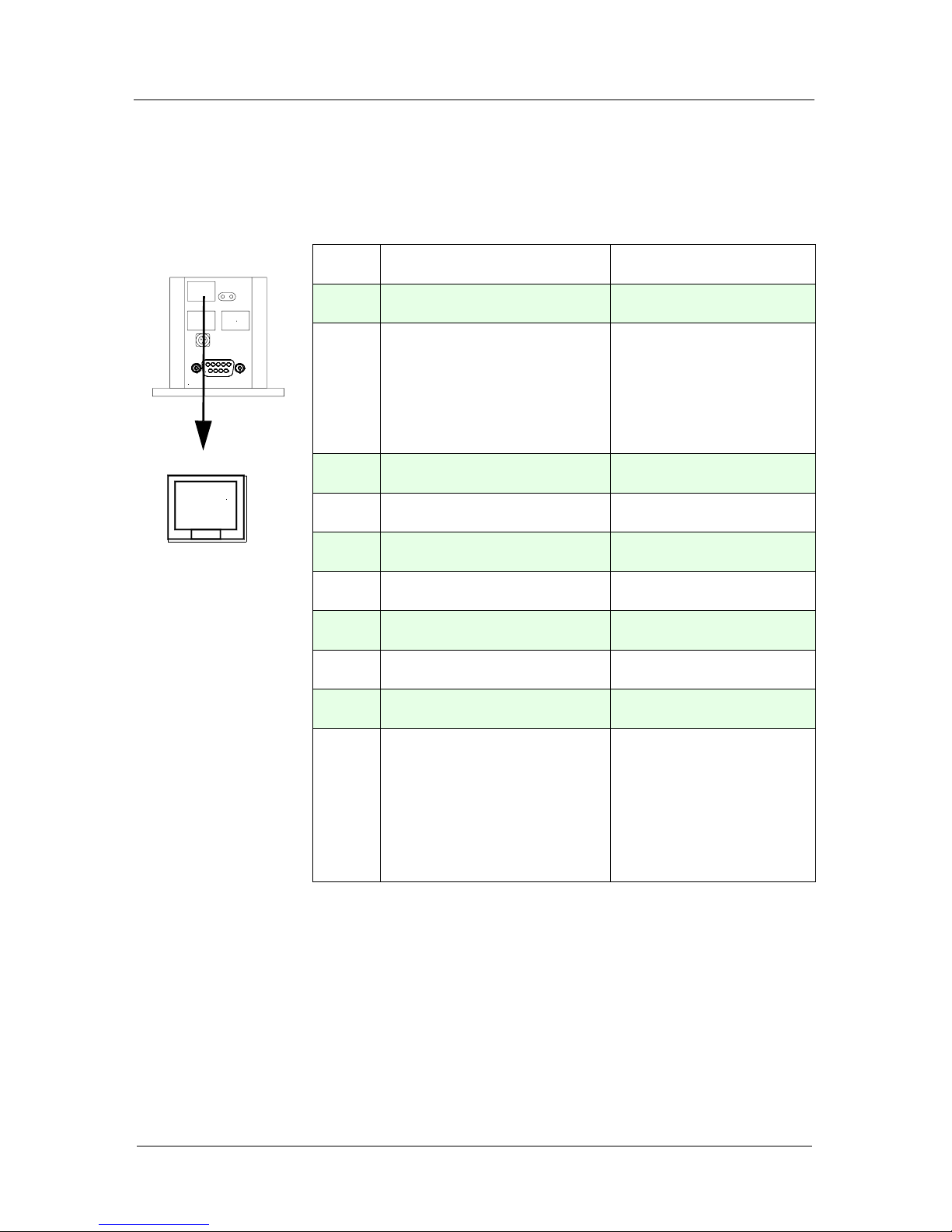
Limit switch connector ( 1 x 10 pin RJ45 ) ...................................25
Page 3

Manual Pollux
Content 3
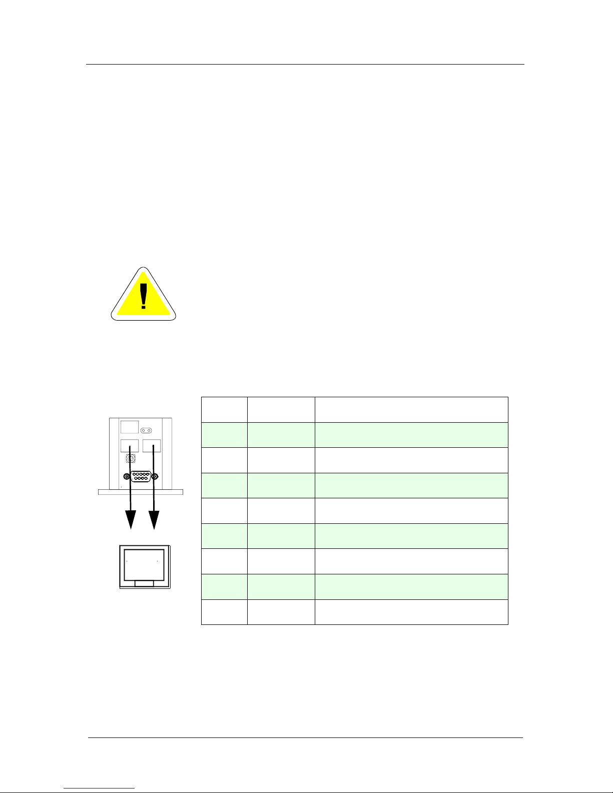
RS-232 connectors (2 x 8 pin RJ45 connector) ............................26
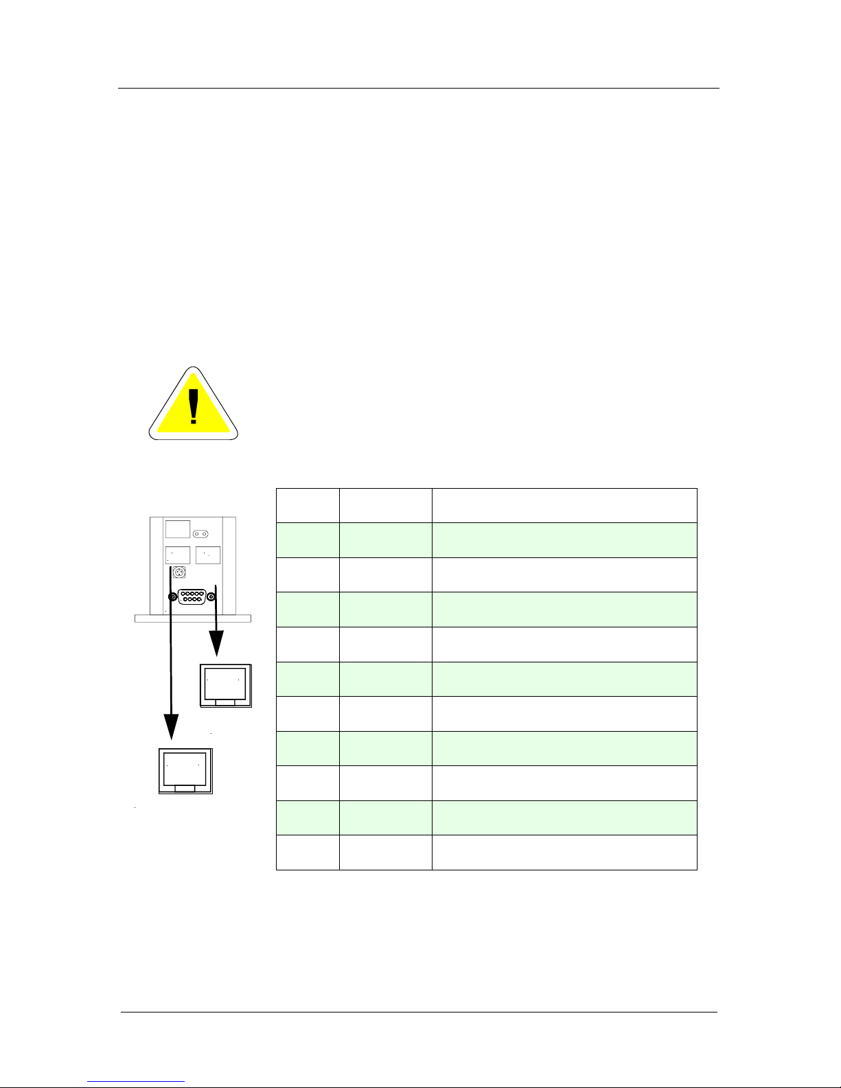
RS-232 connector with "safety device" support (Option) ........... 27
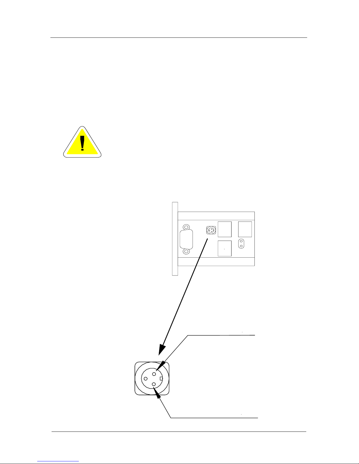
Power Input (3 Pin circular connector) .........................................28
Motor connector Pollux-Box with D" Type 9 (Standard) ............29
Motor connector Pollux-Box with "D" Type 15 ............................30
Pollux Box motor wiring .................................................................31
2 Phase Stepper Motor...........................................................31
For your notices: .............................................................................32
Page 4

Manual Pollux
4
About this documentation
This documentation provides detailed informations on the
hardware features of Pollux Drive or Pollux Box.
Software informations about the Venus-2 command language
are provided in a additional manual.
Page 5
Manual Pollux
5
Symbols in this documentation
To clarify the content following symbols are used.
Symbol Description
Warning.
The informations beside this sign
must be observed strictly
Hint
This function can be released with
a release code
Venus-2 command, see handbook
Option
Venus-2
Page 6

Chapter 1
Manual Pollux
Introduction 6
Introduction
Page 7
Manual Pollux
Introduction 7
Presentation of the controller
Pollux is a extremely compact combination of a high torque
stepper motor and a intelligent positioning controller.
The 1.8° / 0.9°, 42 mm sq. motor is combined with a powerful
motor electronic that provides a calculational step resolution
of minimum 0.001µm and a maximum speed of 40 rev./s.
Controller programming and configuration is executed via a
RS232 interface which allows velocity moves, point-to-point
moves and multiple unit control with only one communication
port.
Optional a CAN-Bus interface is provided.
The ASCII programming language is termed Venus-2.
A On-Board flash memory enables non volatile parametrizing
and software updates via the serial line.
Your dealer will support you if a firmware update is
necessary.
Pollux is available in different variants, which differ from motor
speed, holding torque and the motor assembly.
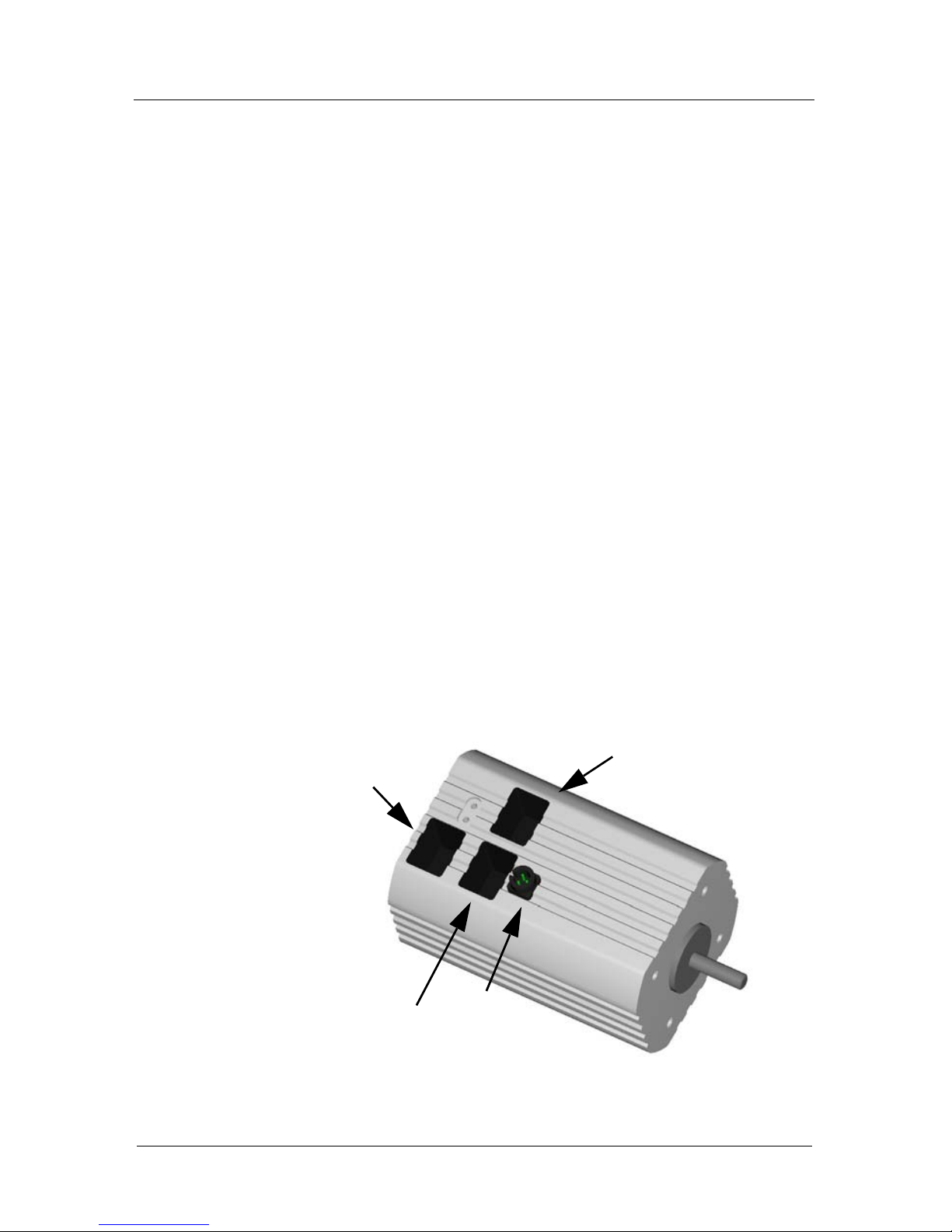
RS-232+Power
RS-232+Power
Power 24V
Limit switch input
(+Safety device)
Page 8
Manual Pollux
Introduction 8
Function survey
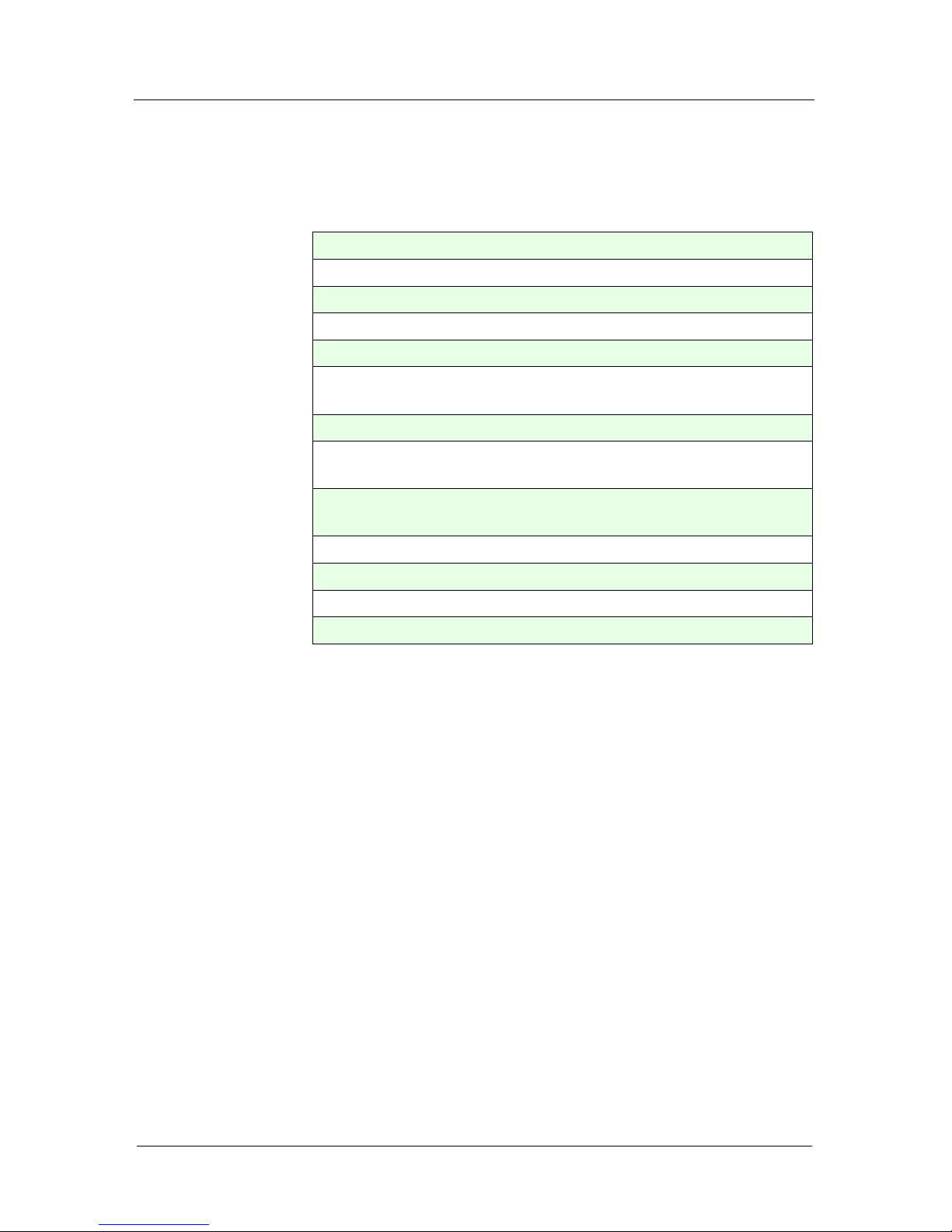
Functions
• Multiple connection, up to 16 devices
• Phase current max 1.2A/Phase
• Velocity: 12.5, 25, 40 rev/s
• Minimum step resolution = 0.001µm
• Limit switch inputs
Homing command and range measure
• RS-232 Interface, 19200 Baud
• Command language
(Venus-2 for Pollux)
• Positioning modes:
Absolute, relative, velocity controlled, synchronous,
• Power Up functions
• Safety device (Motor disable function)
• Firmware update via RS-232 (115000 Baud)
• CAN-Bus Interface (Option)
Page 9
Manual Pollux
Introduction 9
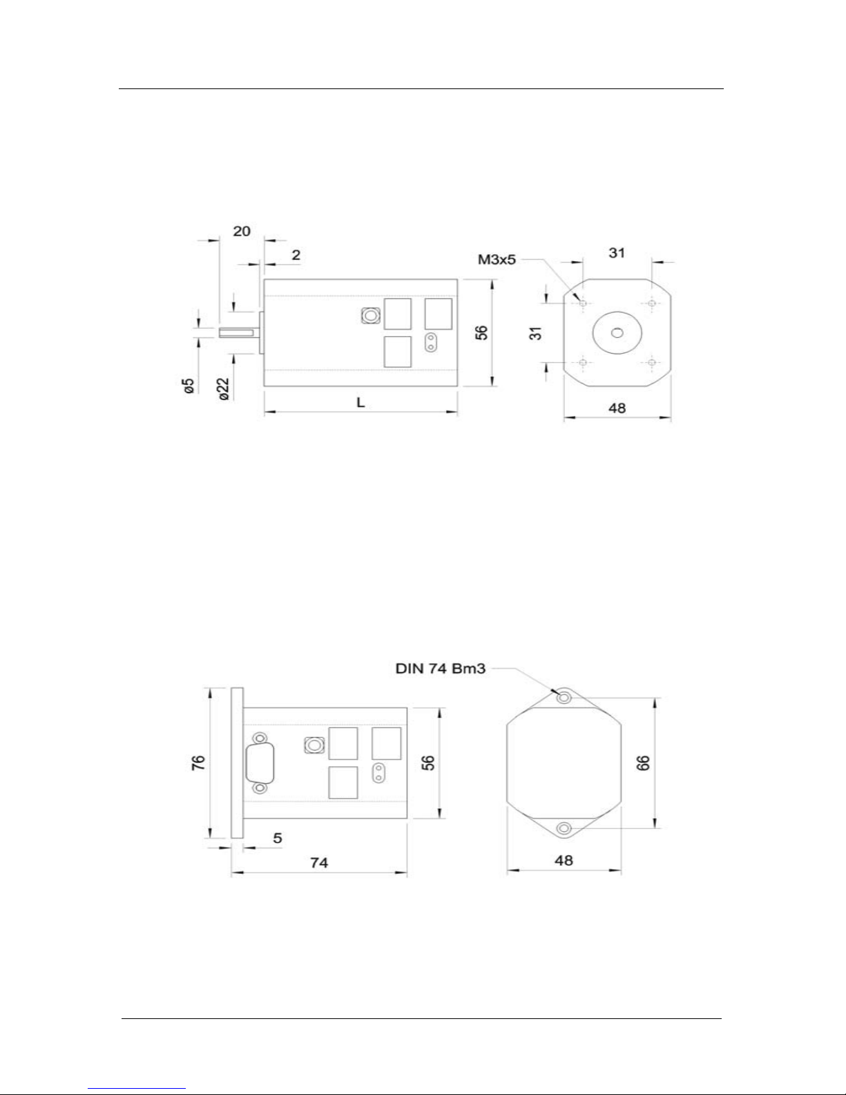
Dimensions Pollux Drive
Dimensions Pollux Box
Pollux Type 1: L=87mm
Pollux Type 2: L=87mm
Pollux Type 3: L=100mm
Pollux Type HT: L=120mm
Page 10

Chapter 2
Manual Pollux
Installation 10
Installation
Page 11
Manual Pollux
Installation 11
Safety notice
The controller is developed, produced, checked and documented in consideration of the relevant standards.
If it is used according to regulations, there are no dangers for
persons and things.
Use according to regulations implies that the device is solely
used in the way that is described in here and that the stated
safety advices are followed.
Page 12

Manual Pollux
Installation 12
Declaration by the manufacturer
The company
MICOS GmbH
Freiburger Strasse 30
D-79427 Eschbach
declares that the product:
Pollux Box, Pollux Drive
intended use:
Positioning Controller
meet the following directives and standards:
Directive 73/23/EEC Directive 89/336/EEC
Electrical Apparatus Electromag. compatibility
Low Voltage Directive
European Standards:
EN61010-1 (08.2002)
EN61326-1
EN61000-3-2, EN61000-3-3
Remarks:
Initial operation of the Pollux Controller sold by us is not
permitted until it has been assured that the machine/system,
in which our Controller is installed, complies with the EU machine guidelines.
L.Amelung (Managing Director)
Eschbach, 01.03.2003
Page 13

Manual Pollux
Installation 13
Power supply
A stabilized 24V power supply is required. The necessary
power depends on the load and speed. Each unit requires a
power supply with minimum 24V/10 W.
Important:
Do not plug in the power cable while the power is On
Page 14
Manual Pollux
Installation 14
Programming via RS-232 interface
Pollux is controlled via the RS-232 interface, therefore a 9 Pin
serial cable with a standard wiring on host side and a 8 pin
RJ45 plug on Pollux side is included in the delivery.
For a daisy chain operation additional cables are necessary.
The command language is "Venus-2 for Pollux".
For simple programming a VT100 ASCII Terminal could be
used to send Venus-2 commands to the controller.
The Venus-2 command language is described in the second
part of this manual.
Important notices about the RS-232 interface
• Preferably use the delivered RS-232 cable
• The RS-232 interface settings of the control unit has to
correspond accurately with the settings of Pollux,
shown in the following table.
• The RS-232 interface of the control unit should not be
be occupied by other programs
RS-232 interface configuration
• Data bits • 8
• Stop bits • 1
• Parity • no
• Handshake • no
• Baudrate • 19200
Page 15

Manual Pollux
Installation 15
Motor characteristic adjustments
The typical motor parameter are determined from the holding
torque, the step angle, the maximum phase current and the
motor pole pairs.
Commands to adjust the speed torque and holding torque
The adjustment is accomplished by the following
Venus-2 commands.
For the Pollux Box Version:
The adjustment to the different motor types is accomplished
with the following Venus-2 commands:
• setphases
• setumotmin
• setumotgrad
• setpolepairs
setumotmin
This command affects the phase
current if the motor is in position.
As a result the holding torque and
power consumption is affected.
setumotgrad
This command affects the phase
current and motor torque if the motor is moving.
Page 16
Manual Pollux
Installation 16
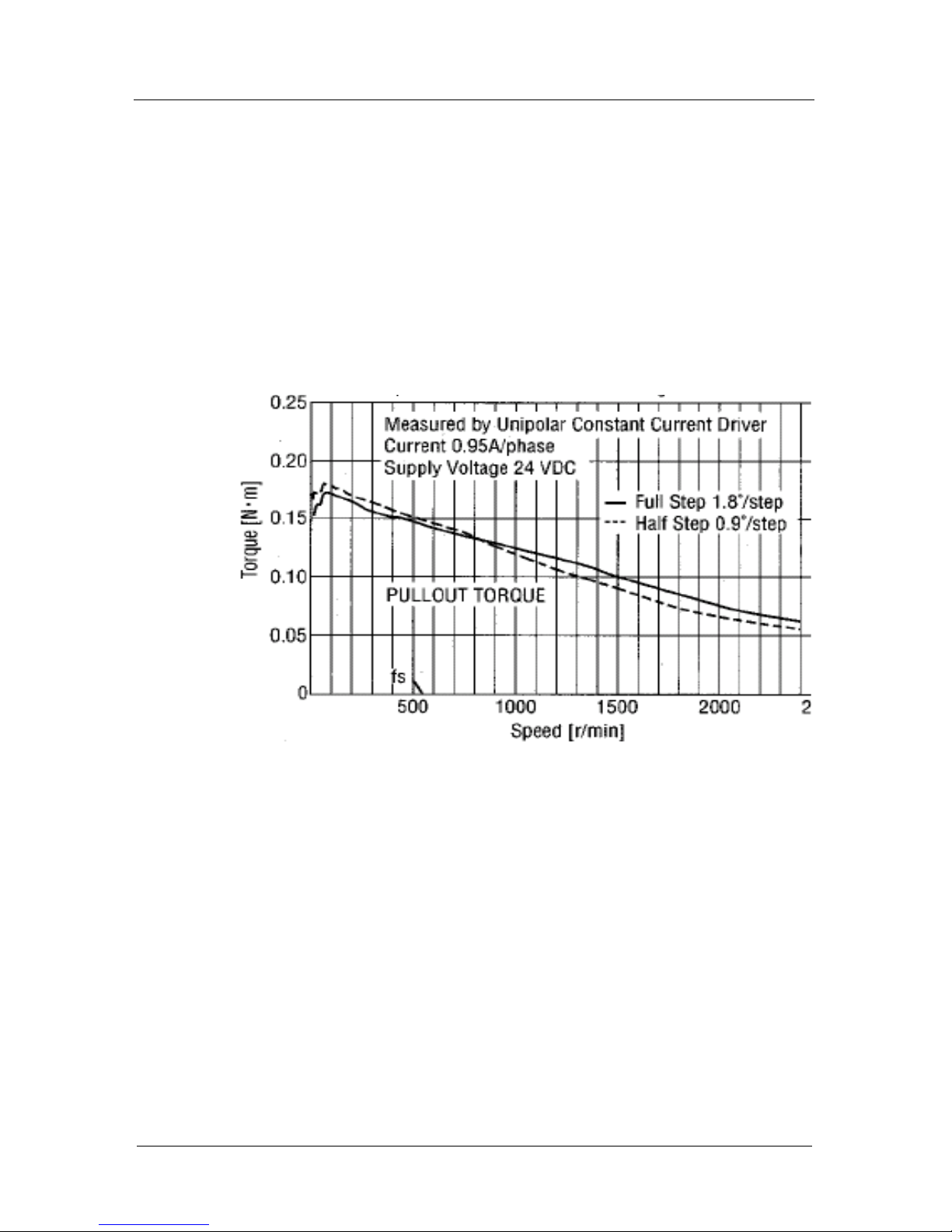
Speed-Torque characteristic
The following diagramms are representing the order of
magnitude of the motor torque.
Pollux-1
Figure 1: Speed Toque characteristic Pollux-1
Page 17
Manual Pollux
Installation 17
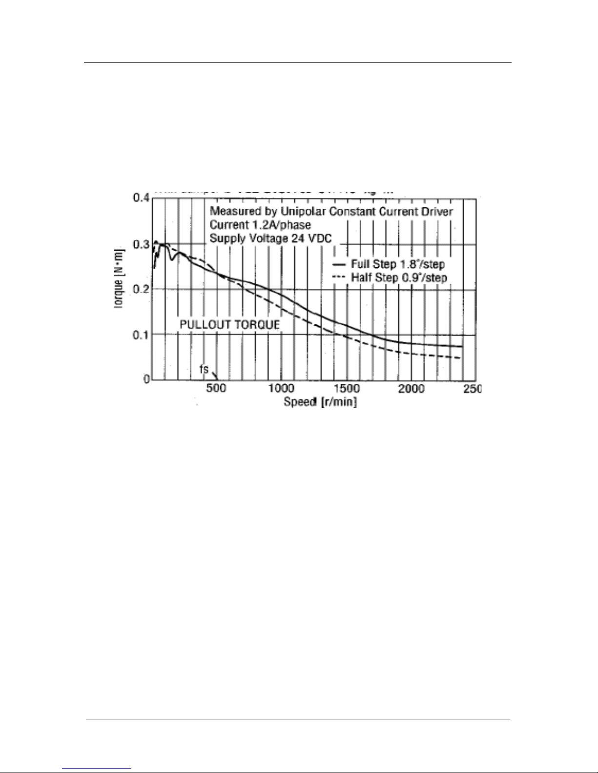
Pollux-2
The following diagramms are representing the order of
magnitude of the motor torqe.
Figure 1: Speed Torque characteristic Pollux-2
Page 18
Manual Pollux
Installation 18
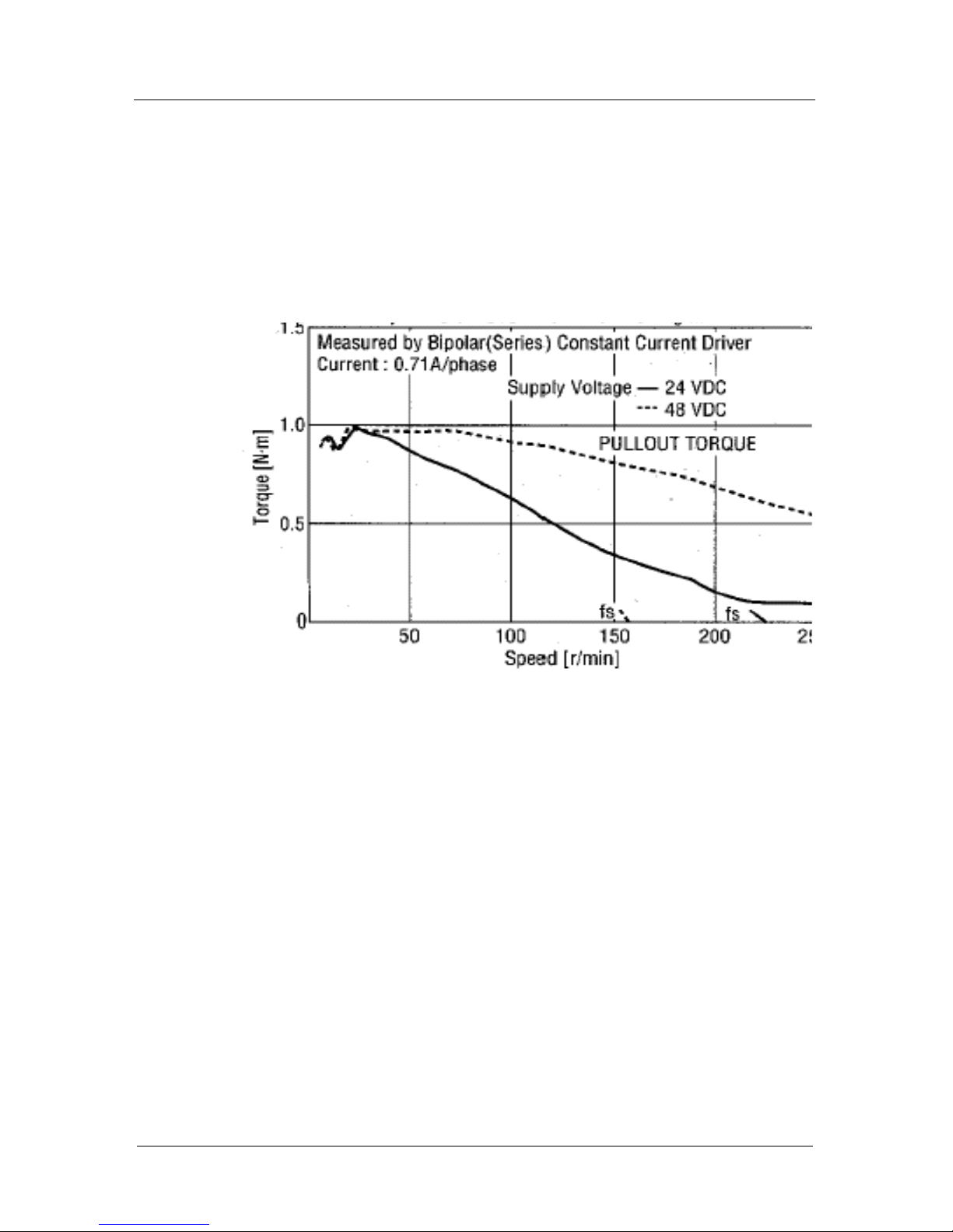
Pollux Box with seperated motor
The following diagramms are representing the order of
magnitude of the motor torqe.
Motor example.
Figure 2: Example Speed-Torque characteristic Pollux-Box
Page 19

Manual Pollux
Installation 19
Limit switches
Limit switch inputs
Pollux provides two endswitch inputs within the 10pin
RJ45 connectors or the "D" Type connector of Pollux-Box.
The switch inputs are termed cal-Input and
rm-Input.
Herewith also the function of these inputs is described.
The limit switch functions supported by Pollux are linked to
these inputs; no other function can be assigned to them.
Limit switch functions
Following limit switch functions are provided.
• move to the cal-switch (Venus-2 command ncal)
The controller moves in negative position until the cal-endswitch is pressed and released.
• move to the rm-switch (Venus-2 command nrm)
The controller moves in positive position until the
rm-switch is pressed and released again.
Switch types
Pollux supports the following endswitch types:
• mechanical switches (opener / closer)
• inductive proximity switches NPN
• photo sensors
The function opener or closer is determined with the
Venus-2 command setsw and is saved with nsave.
Page 20

Manual Pollux
Installation 20
Procedure to configure the limit switch inputs
Go through following steps:
1. Define the switch type settings, see command setsw
2. Store the settings, see command nsave
3. Perform a softreset, see command nreset
Page 21
Manual Pollux
Installation 21
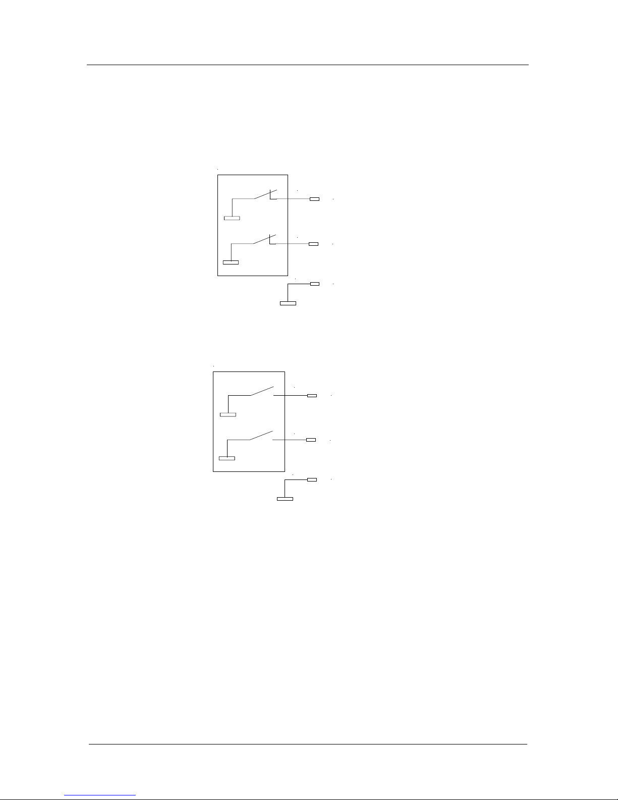
Limit switch wiring via RJ45 connector
Pollux-Box uses the same wiring schemes.
The pin numbers are different. See chapter "Connectors".
cal-Input
rm-Input
2
10
9
GND
Limit switch (normal closed)
cal-Input
rm-Input
2
10
9
GND
Limit switch (normal open)
Page 22
Manual Pollux
Installation 22
Safety device (Option)
For safety reasons Pollux can be equipped with an additional
input to disable motor power. In this state the motor has no
holding torque.
Nevertheless the Pollux controller is able to communicate via
the RS-232 Interface, so the motor disable status can be read
out from the software.
To start the motor driver after a motor disable condition, first
the disable input signal must be removed and a hard reset or
software reset must be performed.
The reply of Venus-2 command nstatus is reflecting the
safety device condition in Bit 7 and Bit 8
See Venus-2 command language.
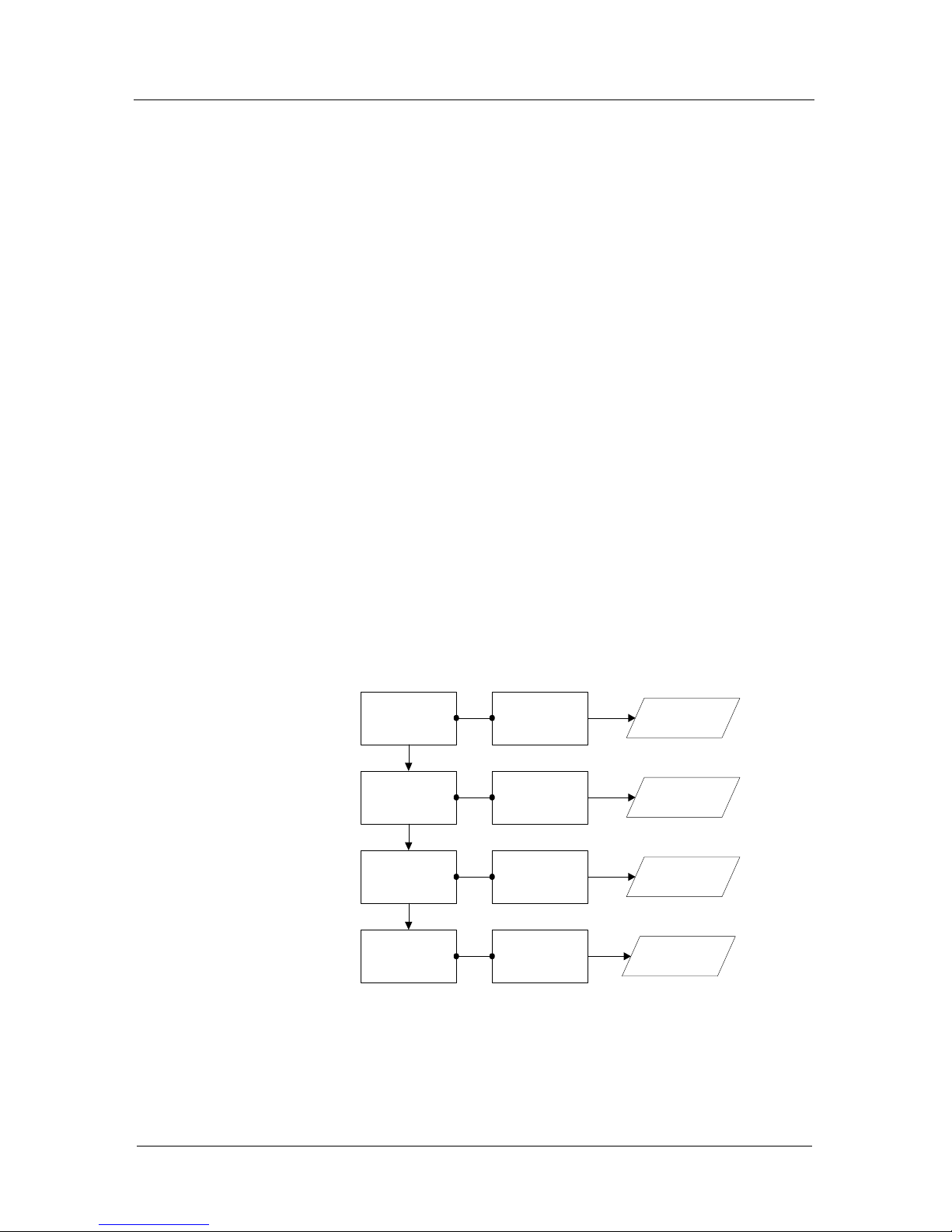
Principal function
Following chart demonstrates the effect of the motor disable
input onto motor driver and controller status replies.
Disable signal
active
Motor disabled
Disable signal not
active
Bit 7 : 0
Bit 8 : 0
Disable signal
removed
Bit 7 : 0
Bit 8 : 1
Bit 7 : 1
Bit 8 : 1
Hardreset or
Softreset (nreset)
Bit 7 : 0
Bit 8 : 0
Motor enabled
Motor still disabled
Motor enabled
Action Effect to motor driver Effect to status reply
Page 23
Manual Pollux
Installation 23
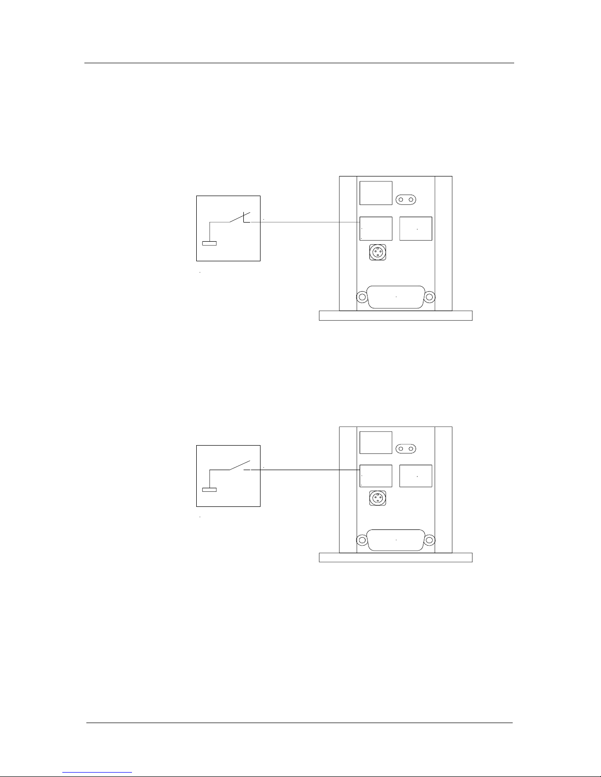
Safety switch wiring (Option)
Motor driver enabled
Motor driver disabled
Motor/Endwitches
motor enable input [1]
1
10pin
Safety switch
Motor/Endwitches
motor enable input [1]
1
10pin
Safety switch
Page 24

Chapter 3
Manual Pollux
24
Connectors
Page 25
Manual Pollux
Connectors 25
Limit switch connector ( 1 x 10 pin RJ45 )
.I
Important:
Do not plug in any cable while the system is running.
Pin Name Description
1 +5V Power output
2
cal-Input
getmotiondir = 0
rm-Input
getmotiondir = 1
Limit switch input
"cal" or "rm",
Depends on the
settings of
setmotiondir
3 not used
4 not used
5 not used
6 not used
7 not used
8
9 GND Ground
10
rm-Input
getmotiondir = 0
cal-Input
getmotiondir = 1
Limit switch input
"cal" or "rm",
Depends on the
settings of
setmotiondir
Motor / Endswitches
1
6
9
5
1
Page 26
Manual Pollux
Connectors 26
RS-232 connectors (2 x 8 pin RJ45 connector)
To simplify daisy chain operation, the Pollux 24V power input
is also integrated in the RS-232 connectors.
In this manner the power supply of maximum two Pollux devices can be daisy chained.
If more than two Pollux devices should connected to the RS232 line, it is recommended to supply the controllers via the
additional circular power connector separately.
If a device is supplied via the power connector, the voltage is
also impressed at the RJ45 connectors.
Important:
Do not plug in any cable while the system is running.
Pin Name Description
1 nc
2nc
3 GND Ground
4 RxD Pollux RS-232 receive input
5 TxD Pollux RS-232 transmit output
6nc
7 GND Ground
824V Power
Motor / Endswitches
1
6
9
5
18
Page 27
Manual Pollux
Connectors 27
RS-232 connector with "safety device" support (Option)
If Pollux supports the safety device function, the hardware is
equipped with one RS-232 10pin RJ45 connector instead of
a 8pin type. With this connector two Pin‘s are added. Therefore the pin arrangement of this connector has changed.
See following table.
Motor enable function:
• If motor enable input is set to GND, the motor is
enabled.
• If motor enable input is open or VCC, the motor is dis-
abled.
9
Pin Name Description
1 Motor enable
2
3
4 GND Ground
5 RxD Pollux RS-232 receive input
6 TxD Pollux RS-232 transmit output
7 nc nc
8 GND Ground
9 24V Power
10 24V Power
Motor enable
RS-232
RS-232
Motor / Endswitches
1
6
9
5
1
RS-232 + Motor enable
10
18
RS-232
24V
Page 28
Manual Pollux
Connectors 28
Power Input (3 Pin circular connector)
With this connector Pollux is provided to connect a power
supply separately.
If the power is connected via the RJ45 connector, the 24V input voltage is also impressed at the circular connector pins.
Important:
Do not plug in the power cable while the power is On.
24V
GND
Pollux Box
Page 29
Manual Pollux
Connectors 29
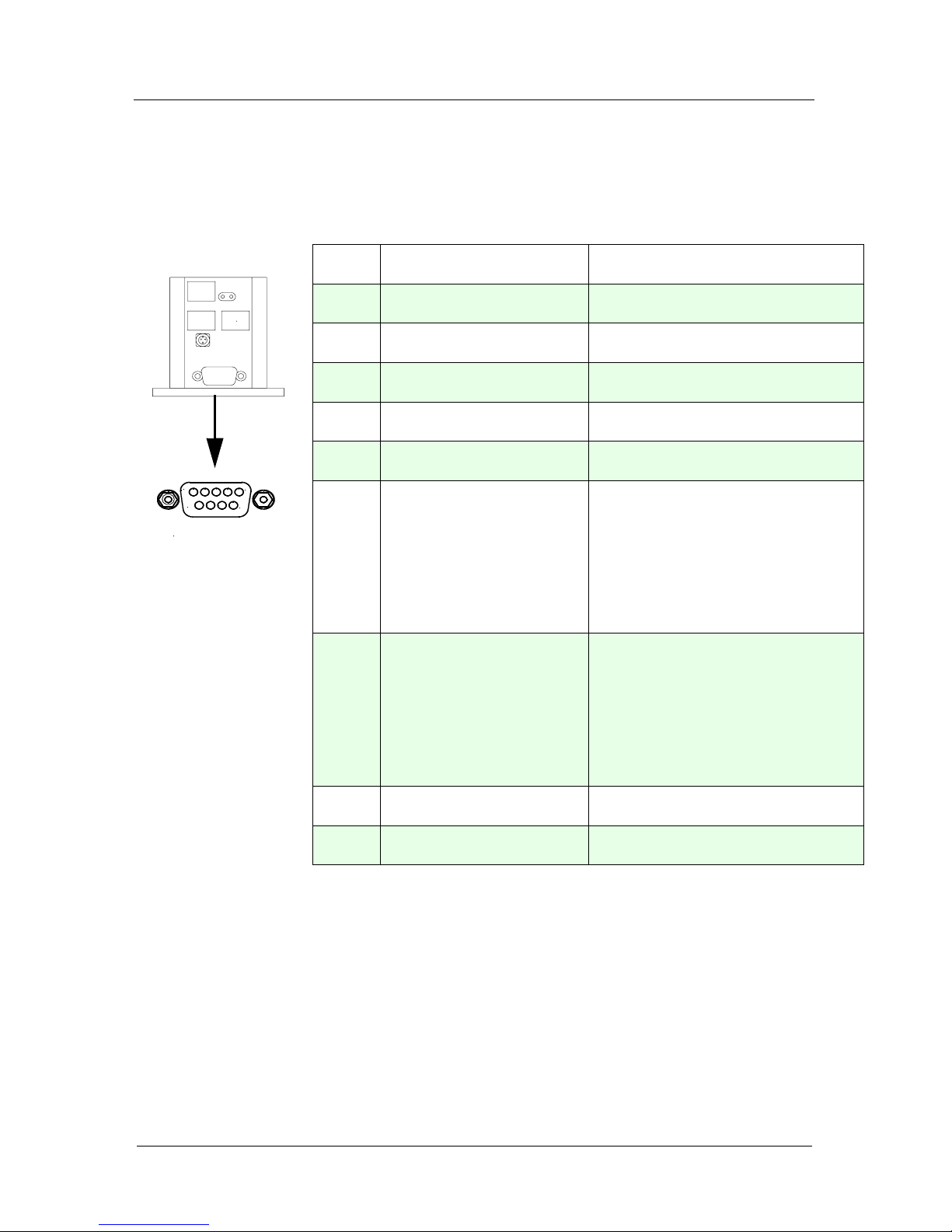
Motor connector Pollux-Box with D" Type 9 (Standard)
.
Pin Name Description
1 Ph 1A Motor phase 1 A
2 Ph 1B Motor phase 1 B
3 Ph 2A Motor phase 2 A
4 Ph 2B Motor phase 2 B
5 GND Ground
6
cal-Input
if getmotiondir = 0
rm-Input
if getmotiondir = 1
Limit switch input "cal" or
"rm".
Depends on the settings of
setmotiondir
7
rm-Input
if getmotiondir = 0
cal-Input
if getmotiondir = 1
Limit switch input "cal" or
"rm",
Depends on the settings of
setmotiondir
8 +5V Power output
9 nc not connected
Motor / Limits
1
6
9
5
Page 30
Manual Pollux
Connectors 30
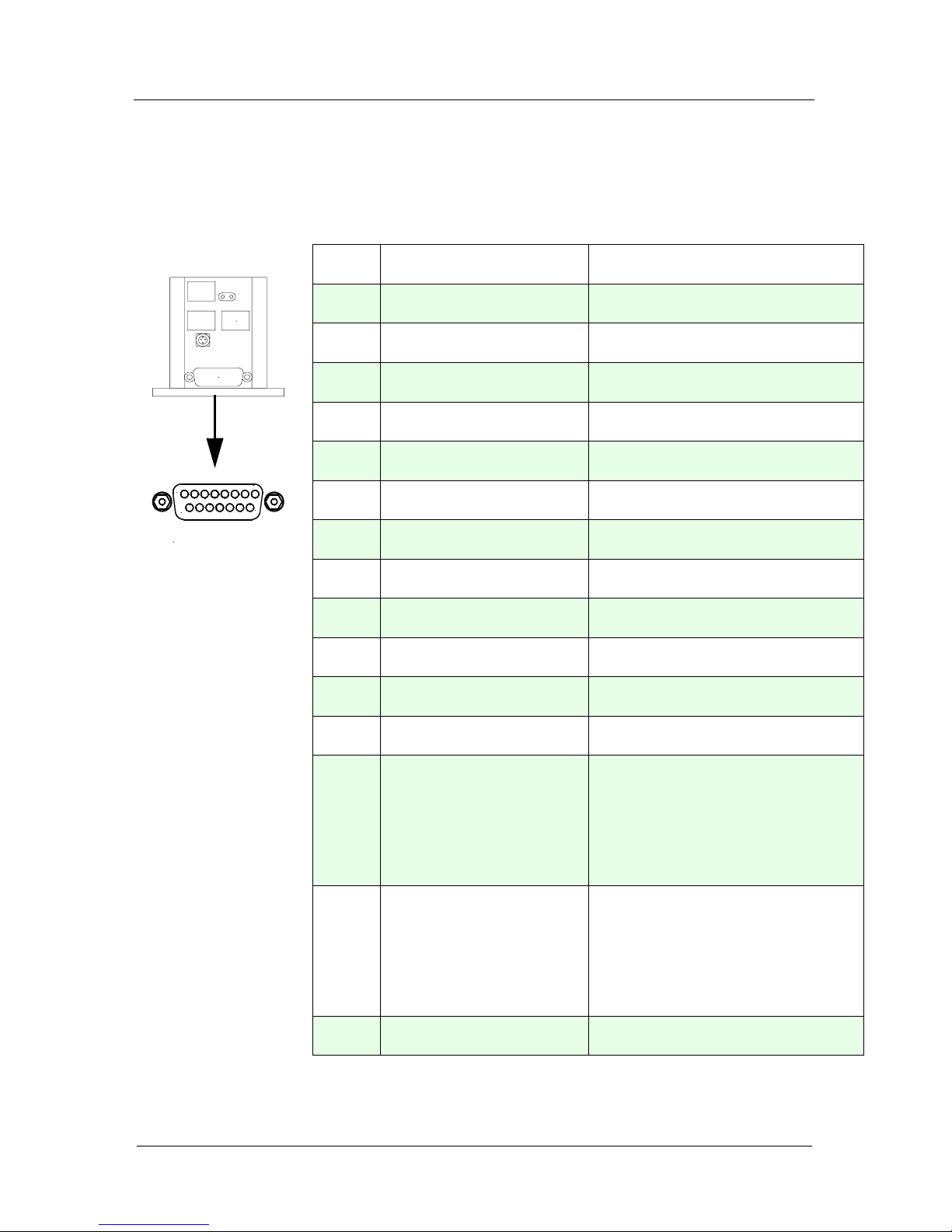
Motor connector Pollux-Box with "D" Type 15
.
Pin Name Description
1 Ph 1A Motor phase 1 A
2 Ph 1B Motor phase 1 B
3 Ph 2A Motor phase 2 A
4 Ph 2B Motor phase 2 B
5 nc not connected
6 +5V Power output
7 nc not connected
8 nc not connected
9 Ph 1A Motor phase 1 A -> (Pin 1)
10 Ph 1B Motor phase 1 B -> (Pin 2)
11 Ph 2A Motor phase 2 A -> (Pin 3)
12 Ph 2B Motor phase 2 B -> (Pin 4)
13
cal-Input
if getmotiondir = 0
rm-Input
if getmotiondir = 1
Limit switch input "cal" or
"rm".
Depends on the settings of
setmotiondir
14
rm-Input
if getmotiondir = 0
cal-Input
if getmotiondir = 1
Limit switch input "cal" or
"rm",
Depends on the settings of
setmotiondir
15 GND Ground
Motor/Endwitches
Motor / Limits
15
8
9
1
Page 31
Manual Pollux
Connectors 31
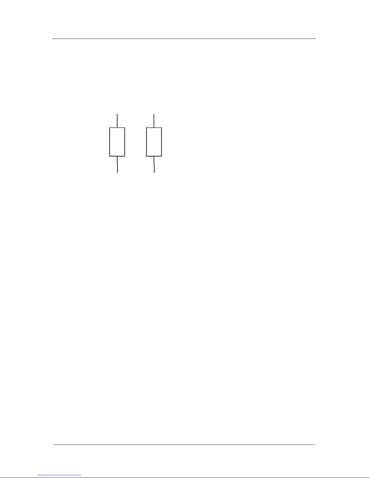
Pollux Box motor wiring
2 Phase Stepper Motor
PH2A
PH2B
PH1B
PH1A
Page 32

Manual Pollux
32
For your notices:
 Loading...