

Micom SWING SW, SWING SWSP Installation Manual
MICOM SWING SW & SWSP
Installation Manual
Page 1
MICOM AUTODOOR
Automatic Swing Door Operator
Model: MICOM SWING
Model SW & SWSP
Original Instructions
INSTALLATION MANUAL
The installation instruction detailed within are soley for profesional installers and not intended to be
handed over to the end user.
OSAKA – JAPAN
www.micomautodoor.com
vers.0001

MICOM SWING SW & SWSP
Installation Manual
Page 2
Contents:
No.
Section
1
INTRODUCTION
2
TECHNICAL SPECIFICATIONS
3
COMPONENTS
4
PARTS
4.1
ID COMPONANT
4.2
ID OPERATOR
5
INSTALLATION OF THE OPERATOR
5.1
PREPARATION - Tools required
5.2
PREPERATION
6
FIXING
6.1
INTRODUCTION
6.2
SET AND ADJUST ARTICULATED ARM (PUSH)
6.3
SET SLIDING ARM (PULL)
6.4
SET UP TENSION STRING
6.5
ADJUST OPENING LIMIT LEVER
7
OPERATION OF THE MICOM SWING-SW & SP SYSTEM
7.1
START UP. SELF-LEARNING
7.2
NORMAL OPERATION
7.3
ELECTRICAL FAULT
7.4
ERRORS
8
CONNECTIONS
8.1
CONNECTION TO THE ELECTRICAL NETWORK
8.2
BASIC INTERNAL CONNECTIONS
9
CONNECTION FROM OTHER COMPONENTS
9.1
P1 connector. Connection from control card for ST-500 access control
9.2
P2 connector. 24V output
9.3
P3 connector. Supervision output(Security Sensor Monitor)
9.4
P4 connector. Emergency stop (Emergency Stop)
9.5
P13 connector. (Emergency Open/Close)
9.6
P5 connector. NIGHT BANK (Forced opening)
9.7
P6 connector. Feed in order to block or automatic 24Vdc latch (Lock)
9.8
P12 connector. lock or automatic Feed in order to block or automatic 12Vdc latch (Lock)
9.9
P9 connector. Internal movement sensor (Internal Sensor)
9.10
P8 connector. External movement sensor(External Sensor)
9.11
P10 connector: Security sensor 1 (Security 1)
9.12
P14 connector: Security sensor 2 (Security 2)
9.13
P7 connector: Selector switch A ( 3 point switch)
9.14
P11 connector: Selector switch B (Digital)
10
DOUBLE DOOR (DUAL) CONNECTION
11
PROBLEMS
11.1
INTERFERENCE
12
PROGRAMMING OF THE CONTROL UNIT
12.1
INTRODUCTION

MICOM SWING SW & SWSP
Installation Manual
Page 3
12.2
PROGRAMMING MENU
12.2.1
Enter into the programming menu
12.2.2
Modify the programming parameter
12.2.3
Exit the programming menu and save the modifications
12.2.4
Programming example
12.2.5
Programming RESET
13
PROGRAMMING PARAMETRES
14
PROBLEM SOLVING. ERROR TABLE
15
MAINTENANCE
16
DECLARATION OF COMPLIANCE
MICOM SWING SW & SWSP
Installation Manual
Page 4
IMPORTANT NOTICE
Please carefully read the instructions before installing the door operator. We hold no
responsibility for loss or damages caused if the following precautions are not
observed.
NOTCIE: It is important for security reasons that all persons follow these instructions.
Please keep these instructions.
When performing Maintenance and Installation tasks, the machine must be disconnected
from the standard electricity supply.
Use the correct electrical feed (See section “2.-Technical Specifications”)
Ensure that the operator is earthed! The operator covering is made of a metal material
which conducts electricity and it is easy for conduction to appear, so please ensure that
the earth cable is connected.
The operator covering is not totally sealed and therefore dampness can destroy the
electronic components within.
Do not remove screws and bolts from the internal structure of the Control Unit. Do not
open, repair or alter any part of the Control Unit. Failure to comply will result in loss of
warranty.
Installation and maintenance of this product can be performed by MICOM authorized
personnel only.
Before plugging in the 3-way connector (power on), make sure that no objects obstruct
the travel of the automatic door.
Follow all the indicated instructions, bearing in mind that an incorrect installation could
provoke serious damage.
It is important to separate Sensor and Selector cables from mains power (230Vac)
cables. As it could provoke the micro-processor to function incorrectly - in the short term
or long term - or even cause irreversible damage.
In the event that all the cables require to be passed through one pipe, those pertaining to
the automatic door must be shielded and must be earthed at both ends. The installation
technicians must not mix the cables within the operator. Always attempt to separate
signals cables (photocell, selector, radar, motor, etc.) from power cables (230V or 110V).
Follow all indicated instructions, as improper installation could cause severe damage.
Please keep these instructions.
Note: Installation instructions detailed here within meet the requirements of BSEN 16005 and if
necessary can be verified.
MICOM SWING SW & SWSP
Installation Manual
Page 5
Notes: For more information, please read the “Section 3.1” of the Installation Manual.
In certain installations of automatic doors, some installers may sometimes place
operation selector cables and power supply cables (230Vac) within the same tube.
This must never be done as it may cause, in the short or long term, the
microprocessor to work incorrectly or to break down irreversibly.
It is advised to avoid placing cables within the same tube. Those belonging to the
automatic door must be shielded and properly grounded at both ends.
It is always necessary to try to separate signal cables (photocell, selector, radars,
engine, etc.) from voltage cables (230V or 110V).
IMPORTANT SAFETY NOTICE!!!
When the door starts for the first time, it will automatically perform a series
of opening and closing cycles (normally between 3 to 5 times) – Known as
teaching or self-learning mode.
Please note these learning cycles are performed at high speed without
safety features enabled.
Keep clear of the entrance and doors. Ensure that no pedestrians pass
through the doors during the initial learning, installation or maintenance.
Keep clear of doors when opening or closing during learning. It is advisable
to identify and restrict the area with warning signs.

MICOM SWING SW & SWSP
Installation Manual
Page 6
1. INTRODUCTION
This instruction manual contains all the information to carry out the installation, maintenance and service
of the MICOM SWING SW and SWING SWSP operators.
These operators are used for to automate swing doors of either one or two panels, both for inside
and outside, opening inwards or outwards.
The mechanism incorporates an opening limiter inside, it is not necessary to have any stopper on the
floor or wall.
The difference between the operators MICOM SWING-SW and MICOM SWING-SP is:
SW: Power Close
SWSP: Spring Close
The MICOM SWING is a non handed swing door operator system is to be utilized for automatic
swinging pedestrian doors. It is suitable for Single and Double applications. Its small size and
attractive housing design will compliment the aesthetics of any door. MICOM SWING SW & SWSP is
very compact, durable and high-quality automatic swing door operator system.
MICOM SWING operator is totally reversible and therefore it can be adapted without needing to
change the mechanics or the programming. It can accommodate Left and Right Push as well as Left
and Right Pull applications.
INSTALLATIONS – TO FOLLOW

MICOM SWING SW & SWSP
Installation Manual
Page 7
2. TECHINCAL SPECIFICATION
MICOM SWING SW
MICOM SWING SWSP
Closure with spring
NO
YES
Arm system
Push (Articulate) and Pull (Slide)
Push & Go
Yes (Adjustable)
Power
230/110VAC 50,60Mhz 2Amp
Opening speed
15-75deg/sec. (Adjustable)
Weight of operator
9kg
Control system
Micro-processor
Braking regulator
Automatic
Opening time
0-60 sec. (10 positions)
Close Pressure
Elimination of door to frame gap.
Electric pressure in 5 steps (adjustable)
Safety Function
Obstruction during opening, door will stop and an alarm will sound.
Obstruction during closing, door will reverse and slowly close.
Obstruction remains, door will stop and an alarm will sound.
Failure Detection
Alarm on failure detection (acoustic and on LED display)
Operation
Continuous opening and closing
Emergency Battery
The door will continue to function in the event of an
electrical outage (optional)
Locking
Electrical Lock of 12/24 VDC (optional)
Operating Environment
Ambient temperature from -20C ~ +50C (no condensation or icing).
Ambient humidity 30% ~ 85%.
(no hazardous materials in the atmosphere)
Max open angle
110 degrees (adjustable).
Max leaf
250 kg
Operator dimensions
120 x 130 x 570 mm (height, depth, length).
MICOM SWING SW & SWSP
Installation Manual
Page 8
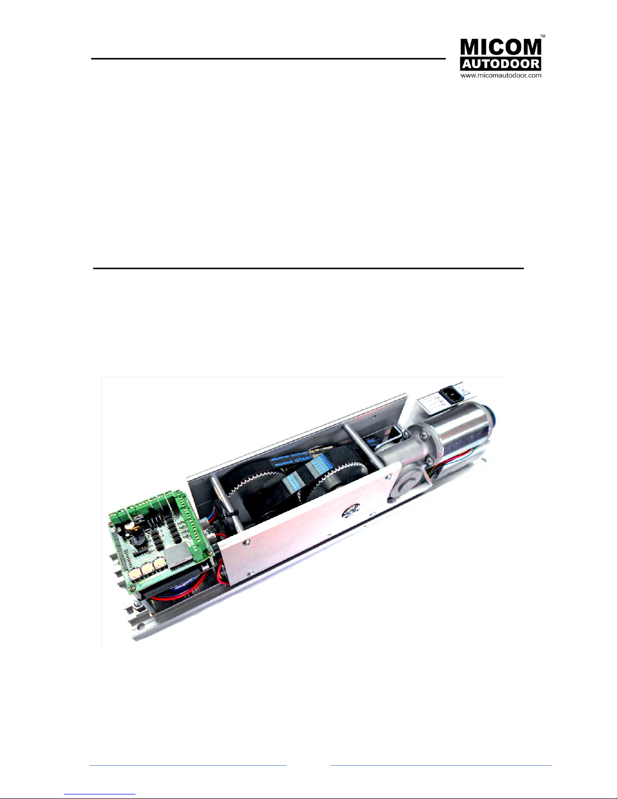
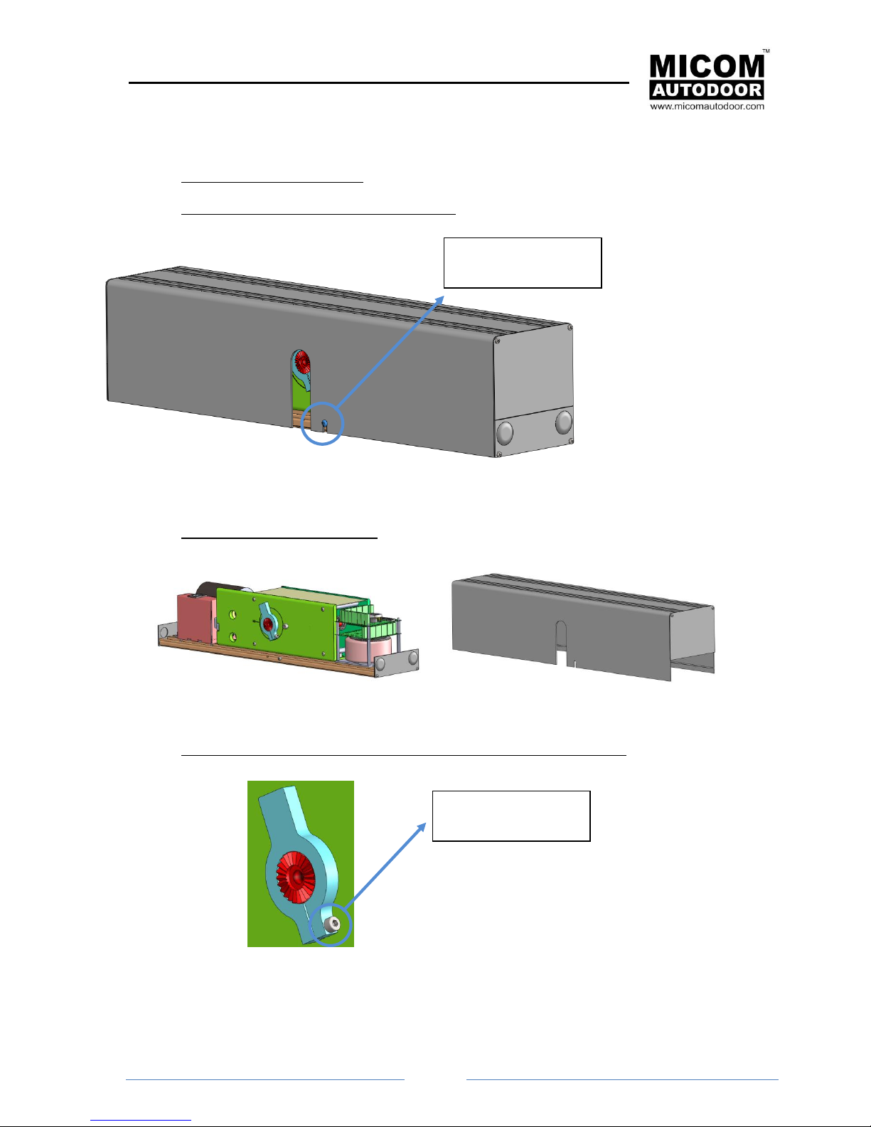
3. COMPONANT PARTS
Exterior views of the operator
Interior view of the operator
2 1 9
7
6
8
10
11 4 5
12
3
MICOM SWING SW & SWSP
Installation Manual
Page 9
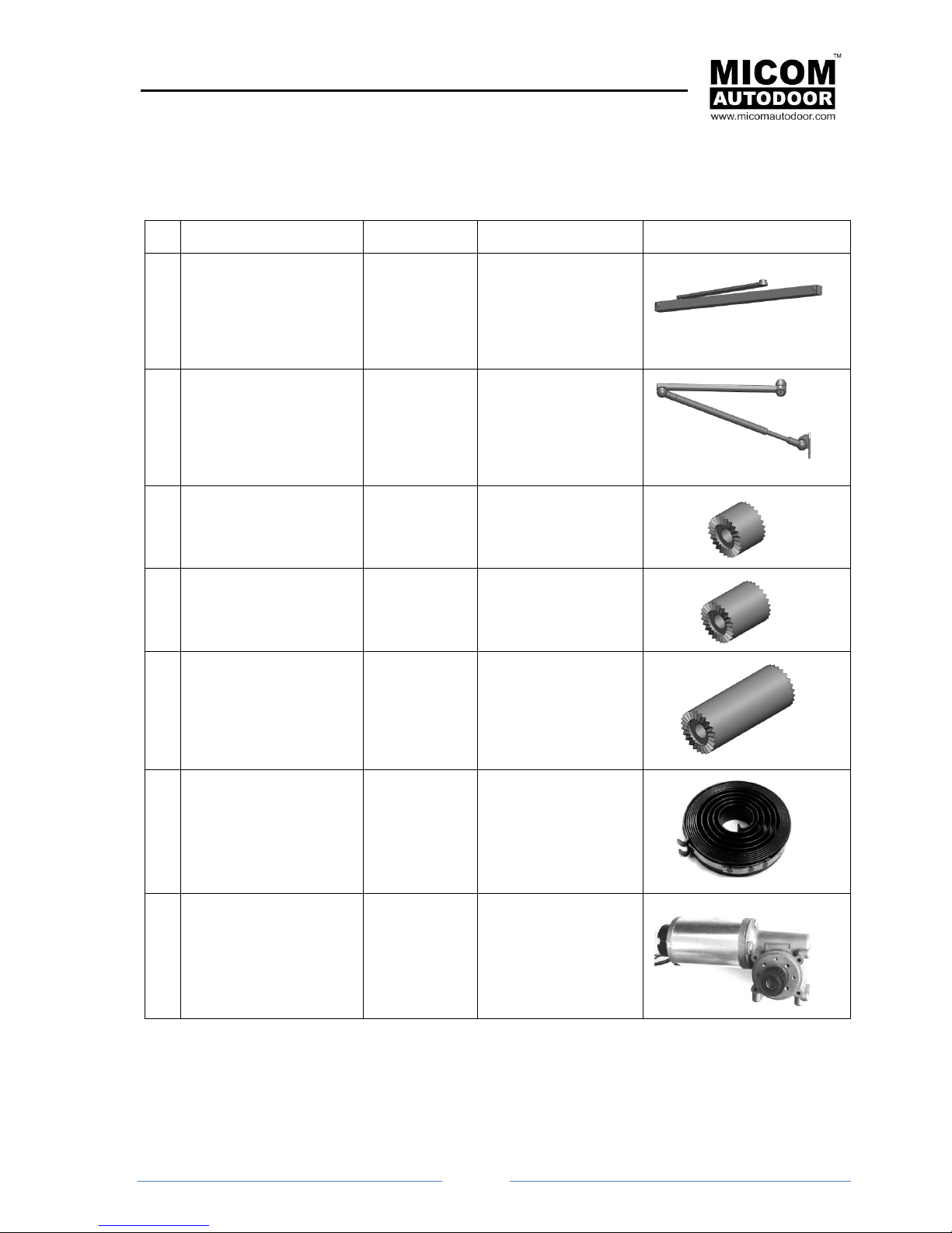
4. PARTS LIST
4.1 List of components and operators
Nº
Components
Reference
Description
Image
01
Sliding arm (pull)
For MI-SW-Pull
2002277
Transmits the force of
the mechanism to the
door. Normally this is
used when the door
panel must open
inwards.
02
Articulated arm(push)
For MI-SW-Push
2002278
Transmits the force of
the mechanism to the
door. Normally this is
used when the door
panel must open
outwards.
03
Separator for MICOM
SWING-SW of 20mm
(optional)
2030001
This allows an increase
the height of the
mechanism by 20 mm
04
Separator for MICOM
SWING -SW of 30mm
(optional)
2030002
This allows an increase
the height of the
mechanism by 30 mm
05
Separator for MICOM
SWING -SW of 60mm
(optional)
2030003
This allows an increase
the height of the
mechanism by 60 mm
06
MICOM SWING-SP
SPRING
Only available for MICOM
SWING-SP operators
2002273
Allows door to close
when there is a power
cut
07
Motor-reducer for
MICOM SWING-SW
2002270
Continuous current
motor
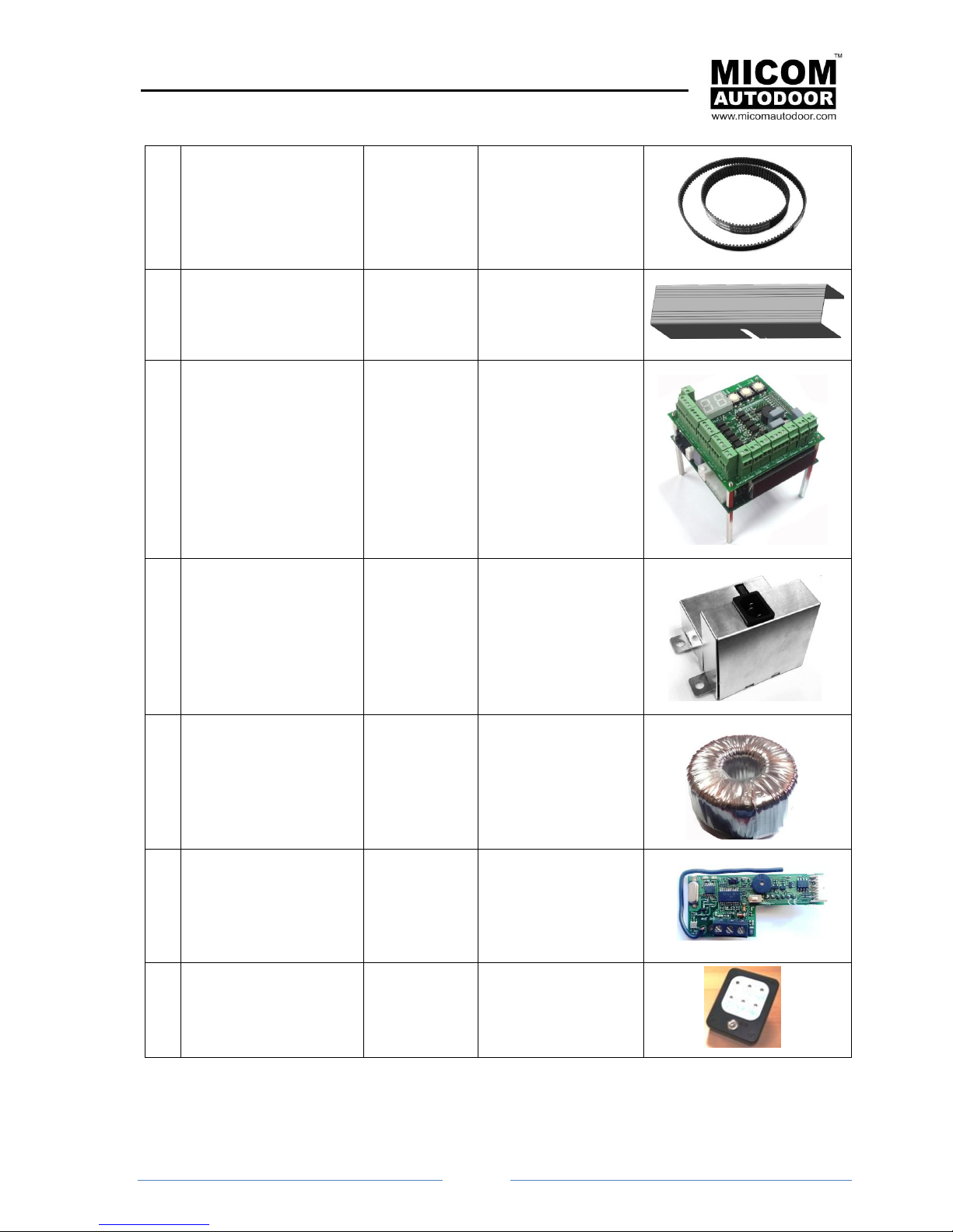
MICOM SWING SW & SWSP
Installation Manual
Page
10
08
25mm BELT for MICOM
SWING -SW
2002271
Belt Reduction Gear
09
Front cover for MICOM
SWING -SW
2002274
Extruded Aluminum
10
Control unit for MICOM
SWING -SW
2002269
Microprocessor Control
11
Feed source for MICOM
SWING -SW
2002276
12
Transformer for MICOM
SWING -SW
2002275
13
Access control card ST500 (option)
5001097
To open the door by
means a radio
transmitter, proximity
key, tag, etc...
14
Digital selector SLD-5
(option)
2002109
Digital selector
MICOM SWING SW & SWSP
Installation Manual
Page
11
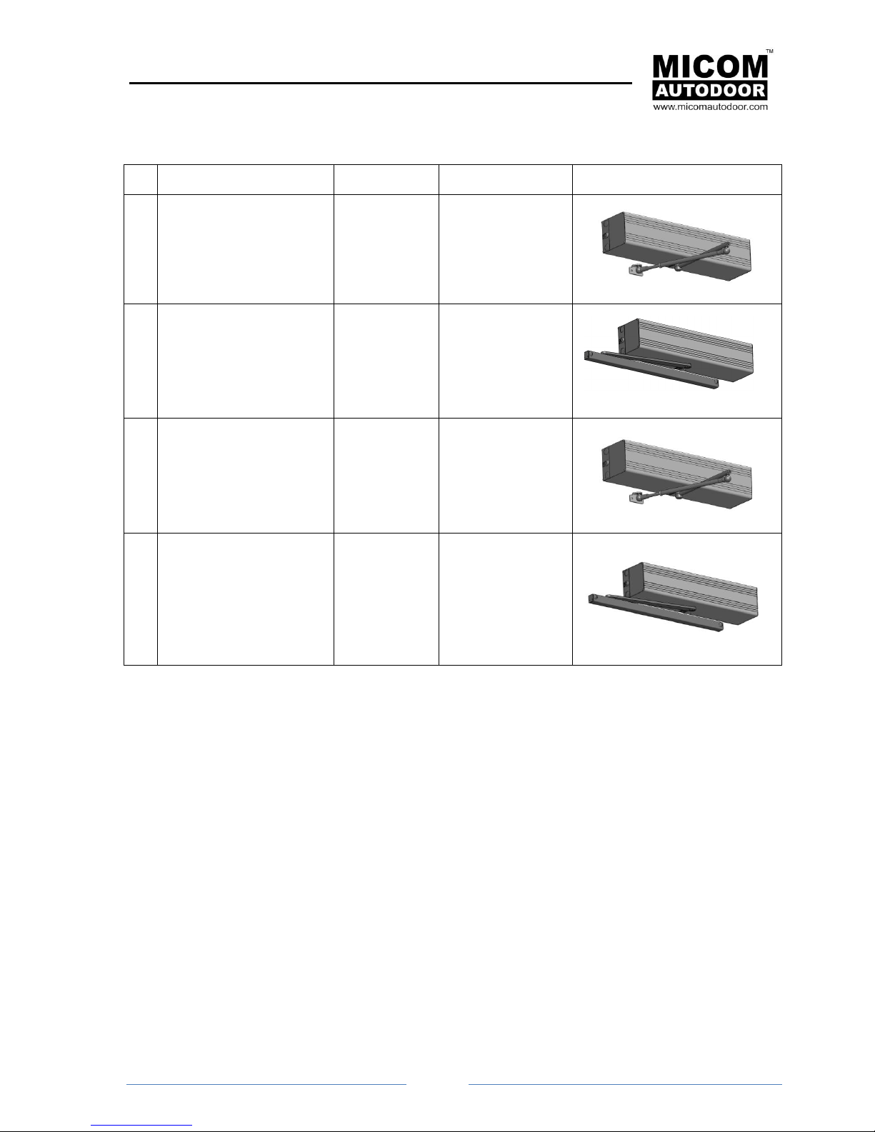
4.2 Identification of Operators
Nº
Operators
Reference
Description
Image
A1
MICOM SWING
SW-Push
2002279
Operator for swing
doors with
articulated arm
A2
MICOM SWING
SW-Pull
2002280
Operator for swing
doors with sliding
arm
A3
MICOM SWING
SWSP-Push
2002281
Operator for swing
doors with
articulated arm and
incorporated closing
spring
A4
MICOM SWING
SWSP-Pull
2002282
Operator for swing
doors with sliding
arm and
incorporated closing
spring
MICOM SWING SW & SWSP
Installation Manual
Page
12
5. INSTALLATION OF THE OPERATOR
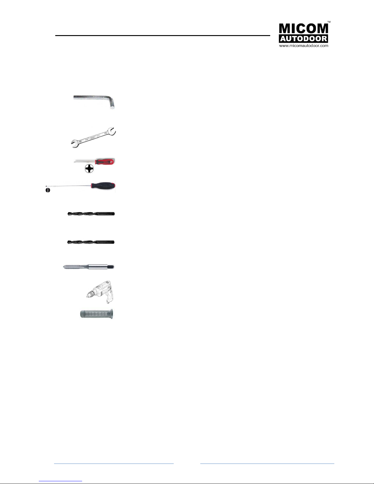
5.1 Preperation - Required tools
Allen key. Sizes:
● 2’5
● 3
● 5
Spanner. Sizes:
● 13
● 14
Phillips screwdriver. Sizes:
● #0
● #1
Flat Screwdriver. Sizes:
● 2
Drill bit for wall/concrete. Sizes:
● 8
● 6
Drill bit for metal. Sizes:
● 5
● 4
Plug for metric thread:
● M6
Drill
Wall plug
MICOM SWING SW & SWSP
Installation Manual
Page
13
5.2 Prepare Operator
● Unpack the operator with care.
● Remove the central screw from the front cover
1. Remove the front cover with care
2. Loosen the screw at the end of the reel so that this can move or turn easily.
Remove screw with
2’5 Allen key
Loosening with Allen
key 3
MICOM SWING SW & SWSP
Installation Manual
Page
14
3. Orientate the operator. Before fixing the operator to the door frame or wall, we should study
the orientation of the same, which can be: Normal or Reversed.
The orientation of the operator depends on the following factors:
opening direction
placement (this can be on the framework or on the door panel)
situation of the door (right or left)
Installation Examples
The operator is totally reversible and therefore it can be adapted to any of the previous factors without
needing to change the mechanics or the programming. It is sufficient to turn it around to orientate it in
one direction or the other.
Therefore, if by mistake the operator was installed upside down. Upon giving the order to open it
actually closes, by simply changing the orientation we can solve the problem.
Normal Position
Reverse Position
Normal Position
(Left Push)
Reverse Position
(Right Push)
Normal Position
(Right Pull)
Reverse Position
(Left Pull)
MICOM SWING SW & SWSP
Installation Manual
Page
15
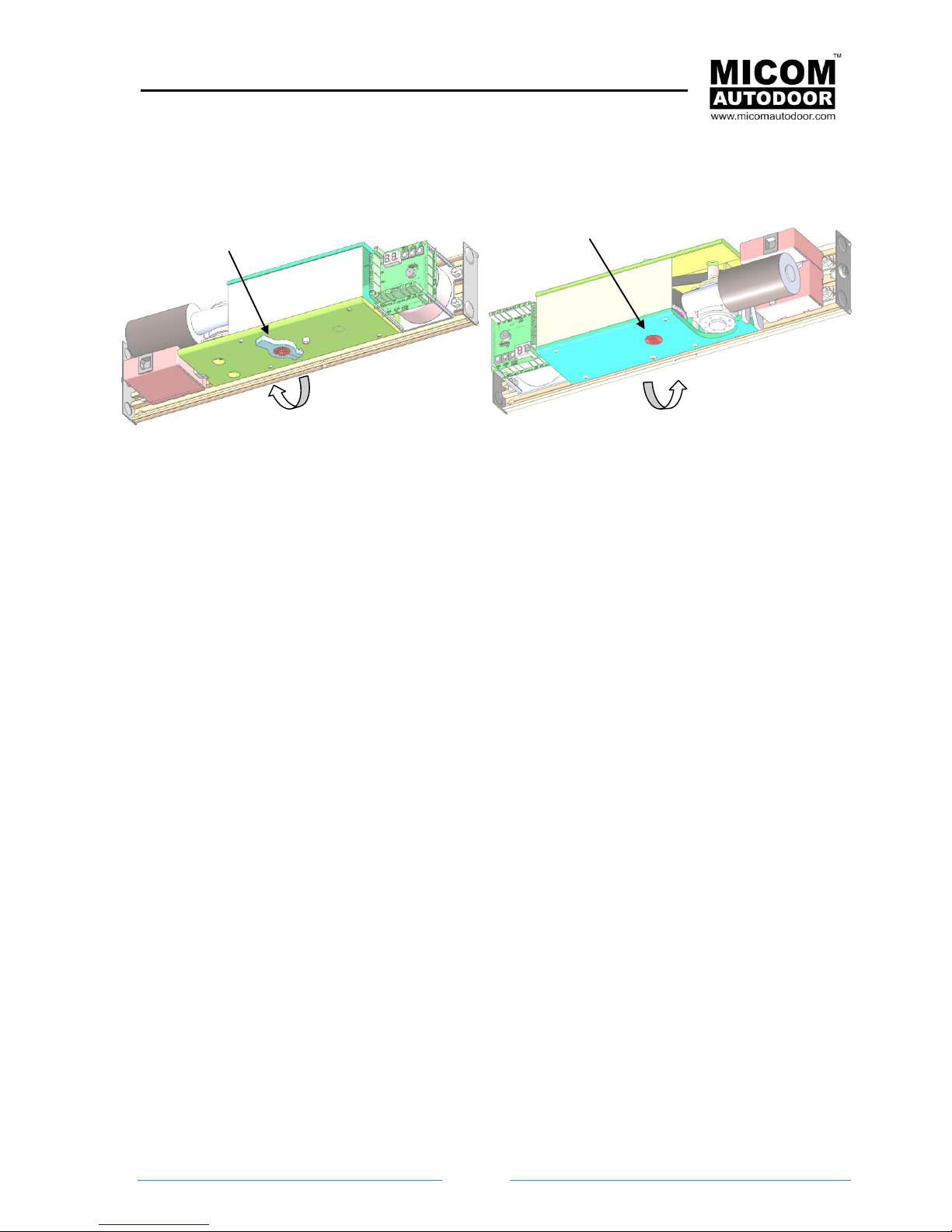
There are two ways to know how to orientate the operator:
A. By Motor Pivot Direction:
A. One method consists of turning the motor’s pivot manually. We can use the operator arm
B.
B. Turning the motor’s pivot manually, we can use the operator arm to assist us. By turning
motor pivot in both directions, using the operator arm to assist in this moment by hand, we
can see that the motor turns with no resistance in one direction; while on the other hand,
turning the motor in the other direction needs greater force. In summary:
Low resistance when turning corresponds to the opening direction of the door.
High resistance when turning corresponds to the closing direction of the door.
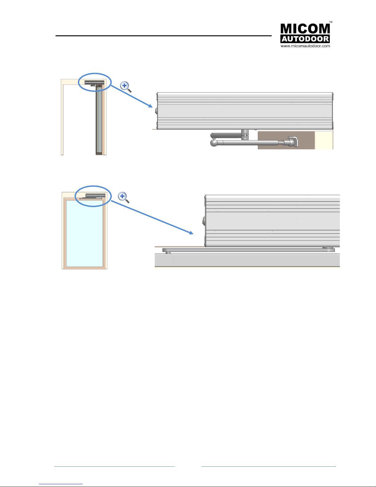
6. FIXING OPERATOR
6.1 Introduction
In order to fix the operator to the door frame, a template is provided with indication as to where the
fixture holes should be. There are 6 holes represented (4 fix the operator to the frame and 2 fix the
operator arm to the door).
These 6 holes are the minimum required that must be used to fix the mechanism correctly.
Before proceeding to fix the operator we recommend keeping the following advice in consideration:
● If the operator is fixed to a thin metal surface (less than 10mm thickness) it is strongly advised
to use threaded screws metric size M6 instead of self-tapping screws.
● If the operator is fixed onto a hollow brick it is strongly advised to use a plastic wall plug and a
threaded rod metric size M6.
Motor Pivot Direction
Motor Pivot Direction
MICOM SWING SW & SWSP
Installation Manual
Page
16
● When the operator with an articulated arm (push) is fixed, a security distance should be used
so that the arm does not hit against the door frame.
● When installing and operator with a sliding arm (pull), leave a safe distance so that the arm
does not knock against the door panel.
Important notice: In the event of using less fixture points than those required, or not following the
previous advice, there is a risk of the mechanism coming unfixed or falling. This would put the people
using the automatic door in danger.
Clearance or security distance
with respect to the door frame.
Security distance = 11mm
Clearance or
security
distance with
respect to the
door panel
(max. 9mm)
MICOM SWING SW & SWSP
Installation Manual
Page
17
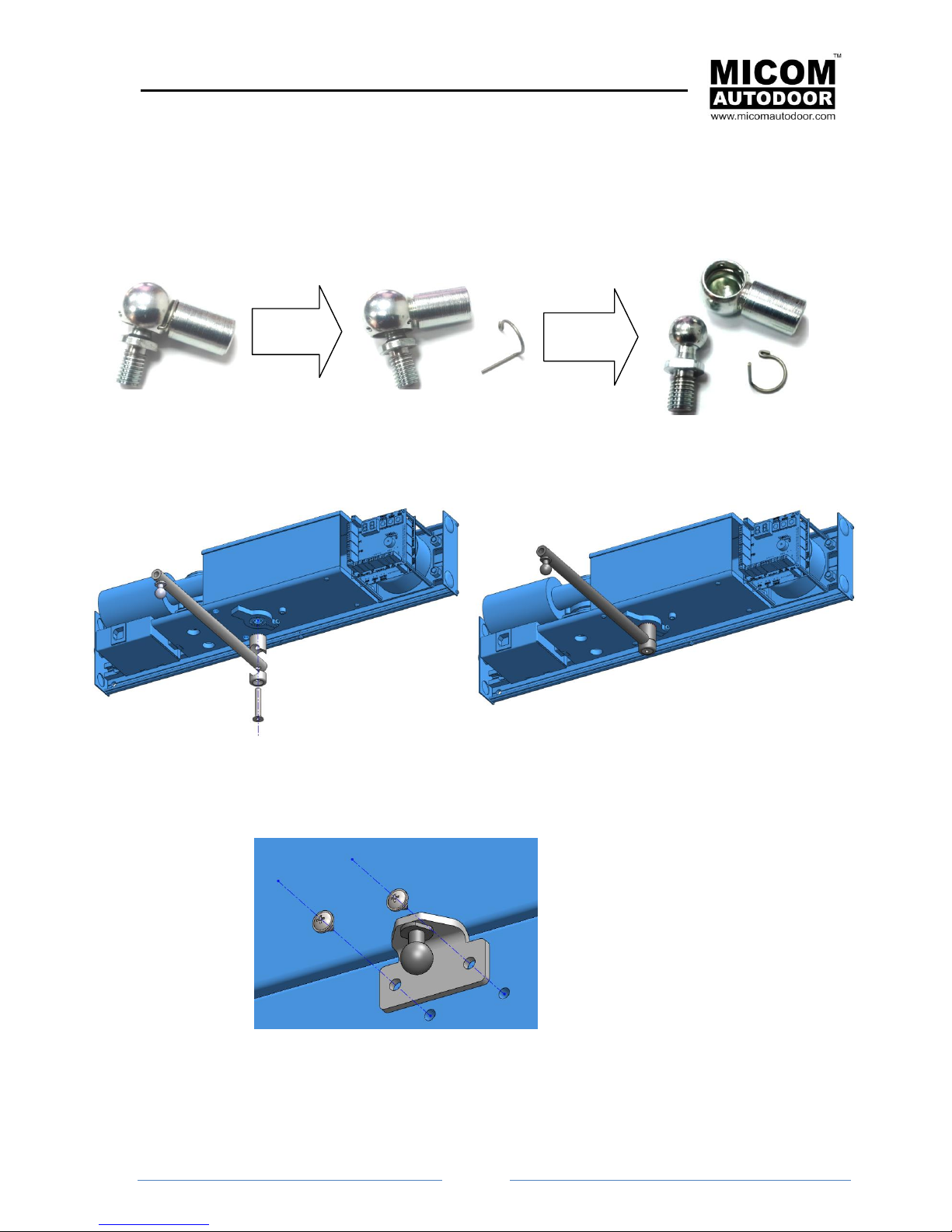
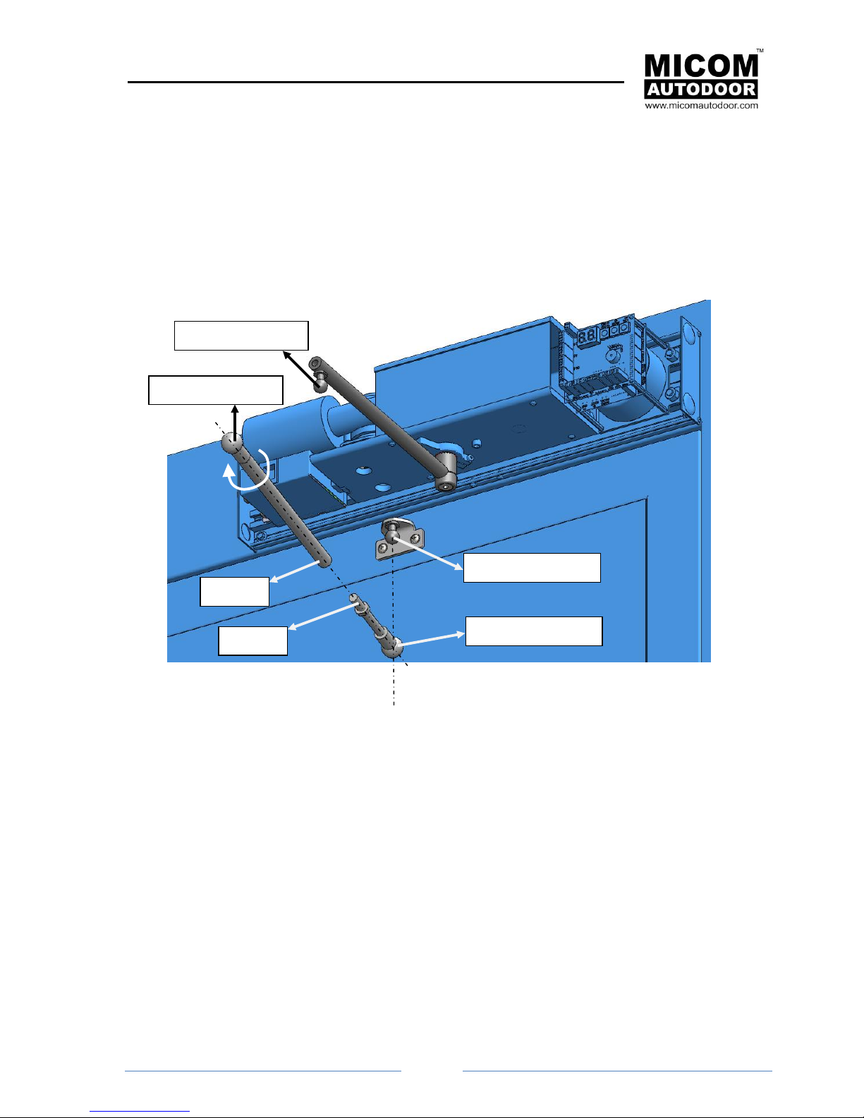
6.2 Fix and Adjust to Articulated (Push) Arm
In order to fix and adjust the articulated arm:
1. Separate the two parts of the arm joints. In order to separate them, you will have to remove
the security ring.
2. Screw in the upper part of the arm.
3. Make two holes in the door by following the indications as shown in drawings.
Remove
circlip
Separate
parts
MICOM SWING SW & SWSP
Installation Manual
Page
18
4. Introduce joint 1 (socket) into joint 2 (plug) (see the following figure).
5. Join “Part A” with “Part B” (see following figure).This will be achieved by screwing it in.
6. Close the door and keep it closed until the arm has been installed.
7. By turning “Part A” we can lengthen or shorten the arm if we turn it in one direction or the
other. Turn “Part A” so that joint 4 (socket) meets up with joint 3 (plug) (see the following
figure).
8. Then place each joint into its security ring.
9. Open and close the door and check that it is working correctly.
Note: Adjust the end of the rod (for more details see section “6.5.-ADJUST OPENING LIMIT”).
Label 2 (plug)
Label 1 (socket)
Part B
Part A
Label 4 (plug)
Joint 3 (socket)
 Loading...