

Page 1
MICOM SWING SW & SWSP
Installation Manual
Page 1
MICOM AUTODOOR
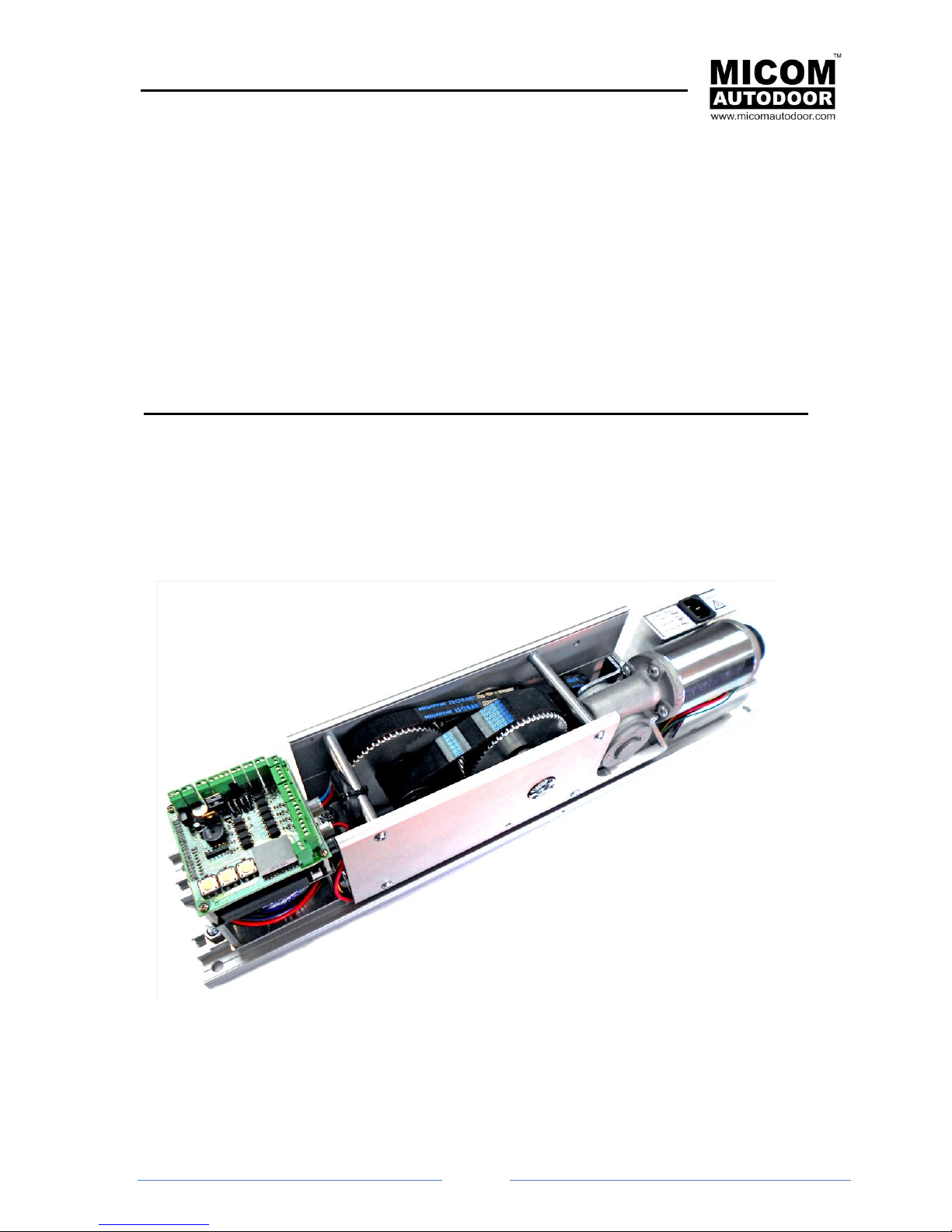
Automatic Swing Door Operator
Model: MICOM SWING
Model SW & SWSP
Original Instructions
INSTALLATION MANUAL
The installation instruction detailed within are soley for profesional installers and not intended to be
handed over to the end user.
OSAKA – JAPAN
www.micomautodoor.com
vers.0001
Page 2

MICOM SWING SW & SWSP
Installation Manual
Page 2
Contents:
No.
Section
1
INTRODUCTION
2
TECHNICAL SPECIFICATIONS
3
COMPONENTS
4
PARTS
4.1
ID COMPONANT
4.2
ID OPERATOR
5
INSTALLATION OF THE OPERATOR
5.1
PREPARATION - Tools required
5.2
PREPERATION
6
FIXING
6.1
INTRODUCTION
6.2
SET AND ADJUST ARTICULATED ARM (PUSH)
6.3
SET SLIDING ARM (PULL)
6.4
SET UP TENSION STRING
6.5
ADJUST OPENING LIMIT LEVER
7
OPERATION OF THE MICOM SWING-SW & SP SYSTEM
7.1
START UP. SELF-LEARNING
7.2
NORMAL OPERATION
7.3
ELECTRICAL FAULT
7.4
ERRORS
8
CONNECTIONS
8.1
CONNECTION TO THE ELECTRICAL NETWORK
8.2
BASIC INTERNAL CONNECTIONS
9
CONNECTION FROM OTHER COMPONENTS
9.1
P1 connector. Connection from control card for ST-500 access control
9.2
P2 connector. 24V output
9.3
P3 connector. Supervision output(Security Sensor Monitor)
9.4
P4 connector. Emergency stop (Emergency Stop)
9.5
P13 connector. (Emergency Open/Close)
9.6
P5 connector. NIGHT BANK (Forced opening)
9.7
P6 connector. Feed in order to block or automatic 24Vdc latch (Lock)
9.8
P12 connector. lock or automatic Feed in order to block or automatic 12Vdc latch (Lock)
9.9
P9 connector. Internal movement sensor (Internal Sensor)
9.10
P8 connector. External movement sensor(External Sensor)
9.11
P10 connector: Security sensor 1 (Security 1)
9.12
P14 connector: Security sensor 2 (Security 2)
9.13
P7 connector: Selector switch A ( 3 point switch)
9.14
P11 connector: Selector switch B (Digital)
10
DOUBLE DOOR (DUAL) CONNECTION
11
PROBLEMS
11.1
INTERFERENCE
12
PROGRAMMING OF THE CONTROL UNIT
12.1
INTRODUCTION
Page 3

MICOM SWING SW & SWSP
Installation Manual
Page 3
12.2
PROGRAMMING MENU
12.2.1
Enter into the programming menu
12.2.2
Modify the programming parameter
12.2.3
Exit the programming menu and save the modifications
12.2.4
Programming example
12.2.5
Programming RESET
13
PROGRAMMING PARAMETRES
14
PROBLEM SOLVING. ERROR TABLE
15
MAINTENANCE
16
DECLARATION OF COMPLIANCE
Page 4
MICOM SWING SW & SWSP
Installation Manual
Page 4
IMPORTANT NOTICE
Please carefully read the instructions before installing the door operator. We hold no
responsibility for loss or damages caused if the following precautions are not
observed.
NOTCIE: It is important for security reasons that all persons follow these instructions.
Please keep these instructions.
When performing Maintenance and Installation tasks, the machine must be disconnected
from the standard electricity supply.
Use the correct electrical feed (See section “2.-Technical Specifications”)
Ensure that the operator is earthed! The operator covering is made of a metal material
which conducts electricity and it is easy for conduction to appear, so please ensure that
the earth cable is connected.
The operator covering is not totally sealed and therefore dampness can destroy the
electronic components within.
Do not remove screws and bolts from the internal structure of the Control Unit. Do not
open, repair or alter any part of the Control Unit. Failure to comply will result in loss of
warranty.
Installation and maintenance of this product can be performed by MICOM authorized
personnel only.
Before plugging in the 3-way connector (power on), make sure that no objects obstruct
the travel of the automatic door.
Follow all the indicated instructions, bearing in mind that an incorrect installation could
provoke serious damage.
It is important to separate Sensor and Selector cables from mains power (230Vac)
cables. As it could provoke the micro-processor to function incorrectly - in the short term
or long term - or even cause irreversible damage.
In the event that all the cables require to be passed through one pipe, those pertaining to
the automatic door must be shielded and must be earthed at both ends. The installation
technicians must not mix the cables within the operator. Always attempt to separate
signals cables (photocell, selector, radar, motor, etc.) from power cables (230V or 110V).
Follow all indicated instructions, as improper installation could cause severe damage.
Please keep these instructions.
Note: Installation instructions detailed here within meet the requirements of BSEN 16005 and if
necessary can be verified.
Page 5
MICOM SWING SW & SWSP
Installation Manual
Page 5
Notes: For more information, please read the “Section 3.1” of the Installation Manual.
In certain installations of automatic doors, some installers may sometimes place
operation selector cables and power supply cables (230Vac) within the same tube.
This must never be done as it may cause, in the short or long term, the
microprocessor to work incorrectly or to break down irreversibly.
It is advised to avoid placing cables within the same tube. Those belonging to the
automatic door must be shielded and properly grounded at both ends.
It is always necessary to try to separate signal cables (photocell, selector, radars,
engine, etc.) from voltage cables (230V or 110V).
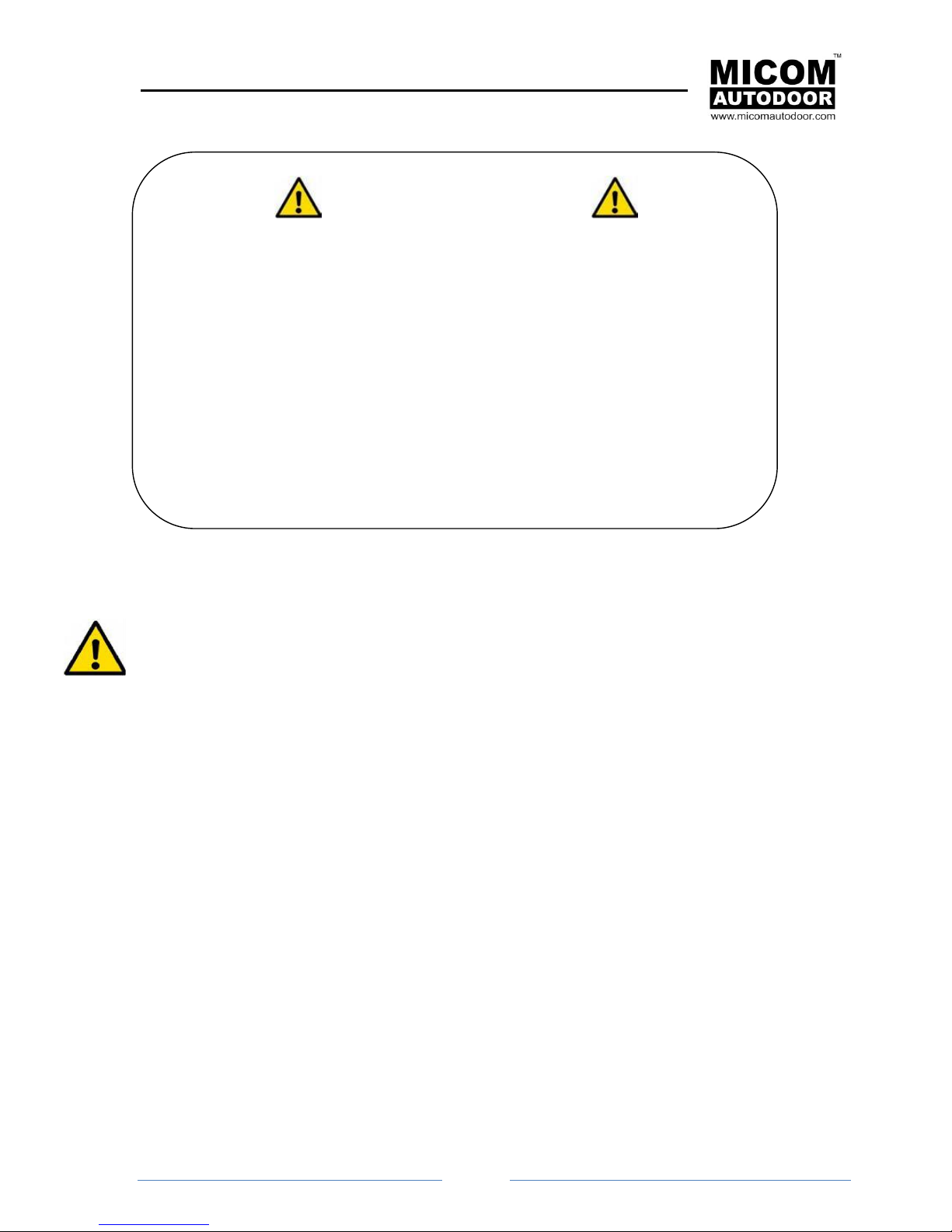
IMPORTANT SAFETY NOTICE!!!
When the door starts for the first time, it will automatically perform a series
of opening and closing cycles (normally between 3 to 5 times) – Known as
teaching or self-learning mode.
Please note these learning cycles are performed at high speed without
safety features enabled.
Keep clear of the entrance and doors. Ensure that no pedestrians pass
through the doors during the initial learning, installation or maintenance.
Keep clear of doors when opening or closing during learning. It is advisable
to identify and restrict the area with warning signs.
Page 6

MICOM SWING SW & SWSP
Installation Manual
Page 6
1. INTRODUCTION
This instruction manual contains all the information to carry out the installation, maintenance and service
of the MICOM SWING SW and SWING SWSP operators.
These operators are used for to automate swing doors of either one or two panels, both for inside
and outside, opening inwards or outwards.
The mechanism incorporates an opening limiter inside, it is not necessary to have any stopper on the
floor or wall.
The difference between the operators MICOM SWING-SW and MICOM SWING-SP is:
SW: Power Close
SWSP: Spring Close
The MICOM SWING is a non handed swing door operator system is to be utilized for automatic
swinging pedestrian doors. It is suitable for Single and Double applications. Its small size and
attractive housing design will compliment the aesthetics of any door. MICOM SWING SW & SWSP is
very compact, durable and high-quality automatic swing door operator system.
MICOM SWING operator is totally reversible and therefore it can be adapted without needing to
change the mechanics or the programming. It can accommodate Left and Right Push as well as Left
and Right Pull applications.
INSTALLATIONS – TO FOLLOW
Page 7

MICOM SWING SW & SWSP
Installation Manual
Page 7
2. TECHINCAL SPECIFICATION
MICOM SWING SW
MICOM SWING SWSP
Closure with spring
NO
YES
Arm system
Push (Articulate) and Pull (Slide)
Push & Go
Yes (Adjustable)
Power
230/110VAC 50,60Mhz 2Amp
Opening speed
15-75deg/sec. (Adjustable)
Weight of operator
9kg
Control system
Micro-processor
Braking regulator
Automatic
Opening time
0-60 sec. (10 positions)
Close Pressure
Elimination of door to frame gap.
Electric pressure in 5 steps (adjustable)
Safety Function
Obstruction during opening, door will stop and an alarm will sound.
Obstruction during closing, door will reverse and slowly close.
Obstruction remains, door will stop and an alarm will sound.
Failure Detection
Alarm on failure detection (acoustic and on LED display)
Operation
Continuous opening and closing
Emergency Battery
The door will continue to function in the event of an
electrical outage (optional)
Locking
Electrical Lock of 12/24 VDC (optional)
Operating Environment
Ambient temperature from -20C ~ +50C (no condensation or icing).
Ambient humidity 30% ~ 85%.
(no hazardous materials in the atmosphere)
Max open angle
110 degrees (adjustable).
Max leaf
250 kg
Operator dimensions
120 x 130 x 570 mm (height, depth, length).
Page 8
MICOM SWING SW & SWSP
Installation Manual
Page 8
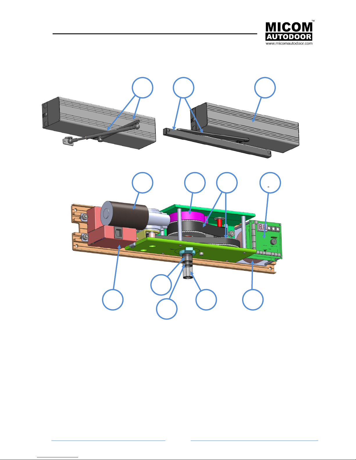
3. COMPONANT PARTS
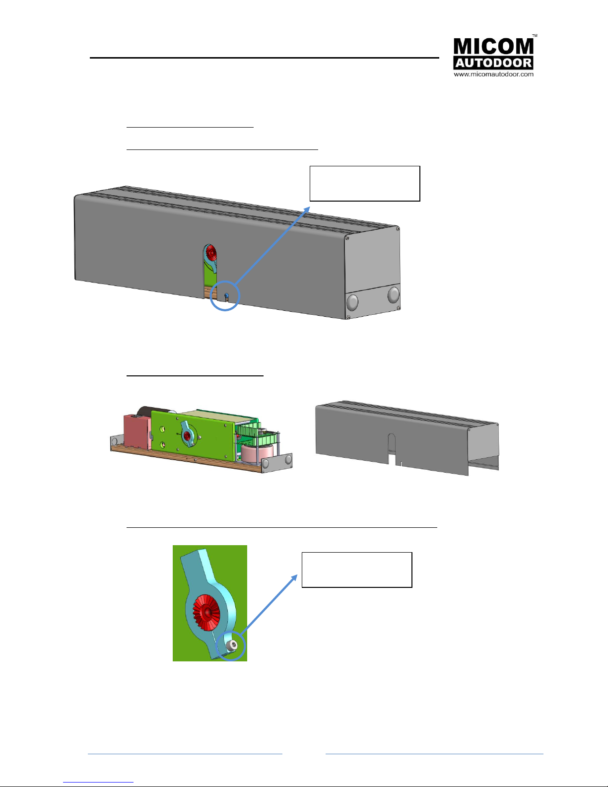
Exterior views of the operator
Interior view of the operator
2 1 9
7
6
8
10
11 4 5
12
3
Page 9
MICOM SWING SW & SWSP
Installation Manual
Page 9
4. PARTS LIST
4.1 List of components and operators
Nº
Components
Reference
Description
Image
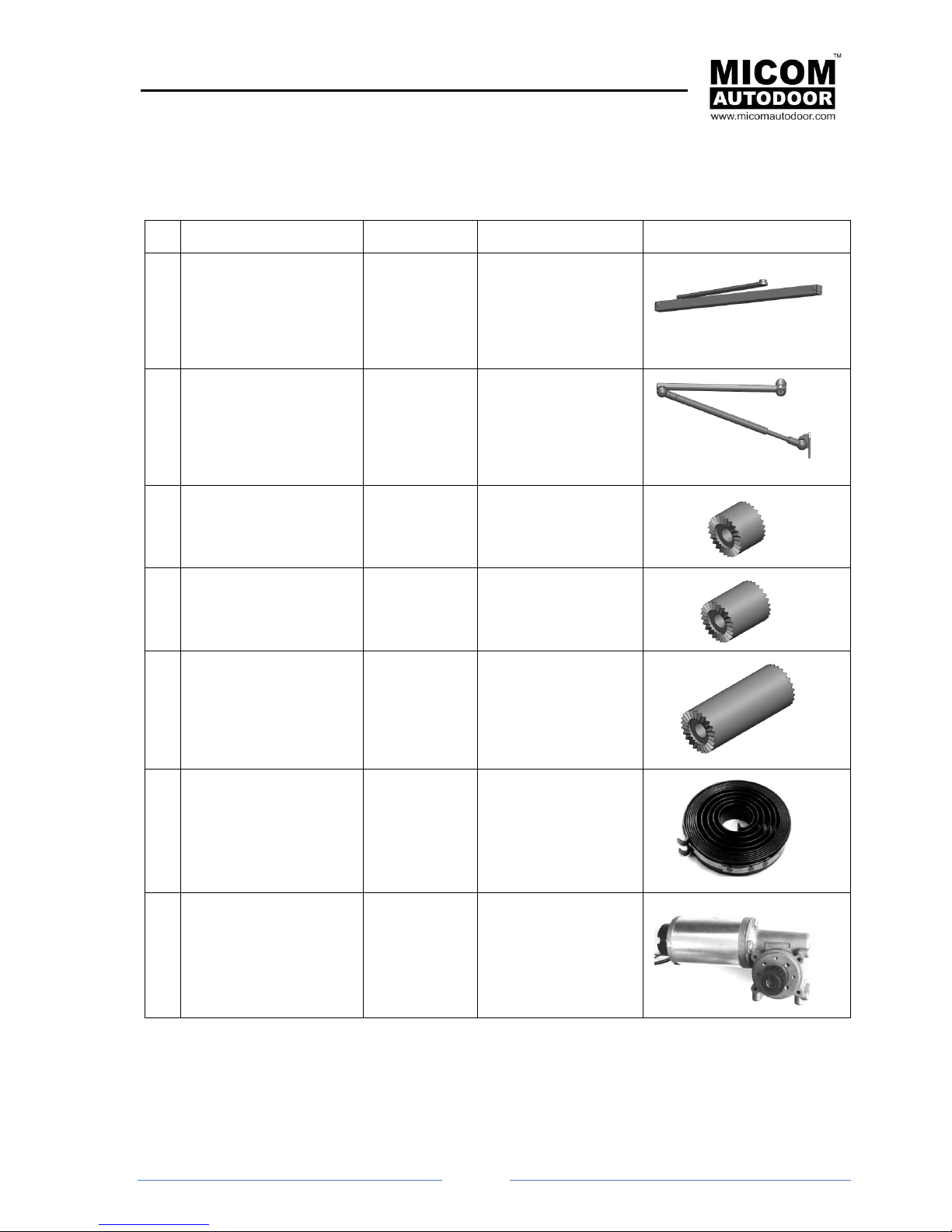
01
Sliding arm (pull)
For MI-SW-Pull
2002277
Transmits the force of
the mechanism to the
door. Normally this is
used when the door
panel must open
inwards.
02
Articulated arm(push)
For MI-SW-Push
2002278
Transmits the force of
the mechanism to the
door. Normally this is
used when the door
panel must open
outwards.
03
Separator for MICOM
SWING-SW of 20mm
(optional)
2030001
This allows an increase
the height of the
mechanism by 20 mm
04
Separator for MICOM
SWING -SW of 30mm
(optional)
2030002
This allows an increase
the height of the
mechanism by 30 mm
05
Separator for MICOM
SWING -SW of 60mm
(optional)
2030003
This allows an increase
the height of the
mechanism by 60 mm
06
MICOM SWING-SP
SPRING
Only available for MICOM
SWING-SP operators
2002273
Allows door to close
when there is a power
cut
07
Motor-reducer for
MICOM SWING-SW
2002270
Continuous current
motor
Page 10
MICOM SWING SW & SWSP
Installation Manual
Page
10
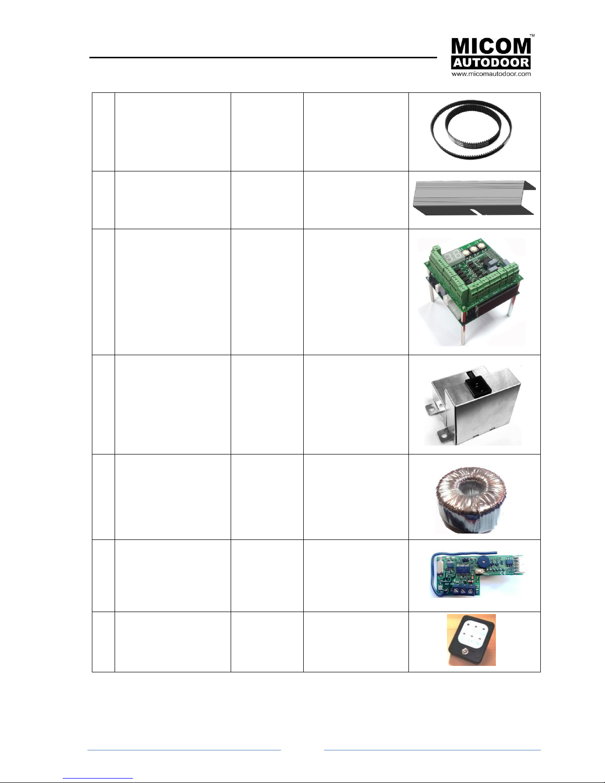
08
25mm BELT for MICOM
SWING -SW
2002271
Belt Reduction Gear
09
Front cover for MICOM
SWING -SW
2002274
Extruded Aluminum
10
Control unit for MICOM
SWING -SW
2002269
Microprocessor Control
11
Feed source for MICOM
SWING -SW
2002276
12
Transformer for MICOM
SWING -SW
2002275
13
Access control card ST500 (option)
5001097
To open the door by
means a radio
transmitter, proximity
key, tag, etc...
14
Digital selector SLD-5
(option)
2002109
Digital selector
Page 11
MICOM SWING SW & SWSP
Installation Manual
Page
11
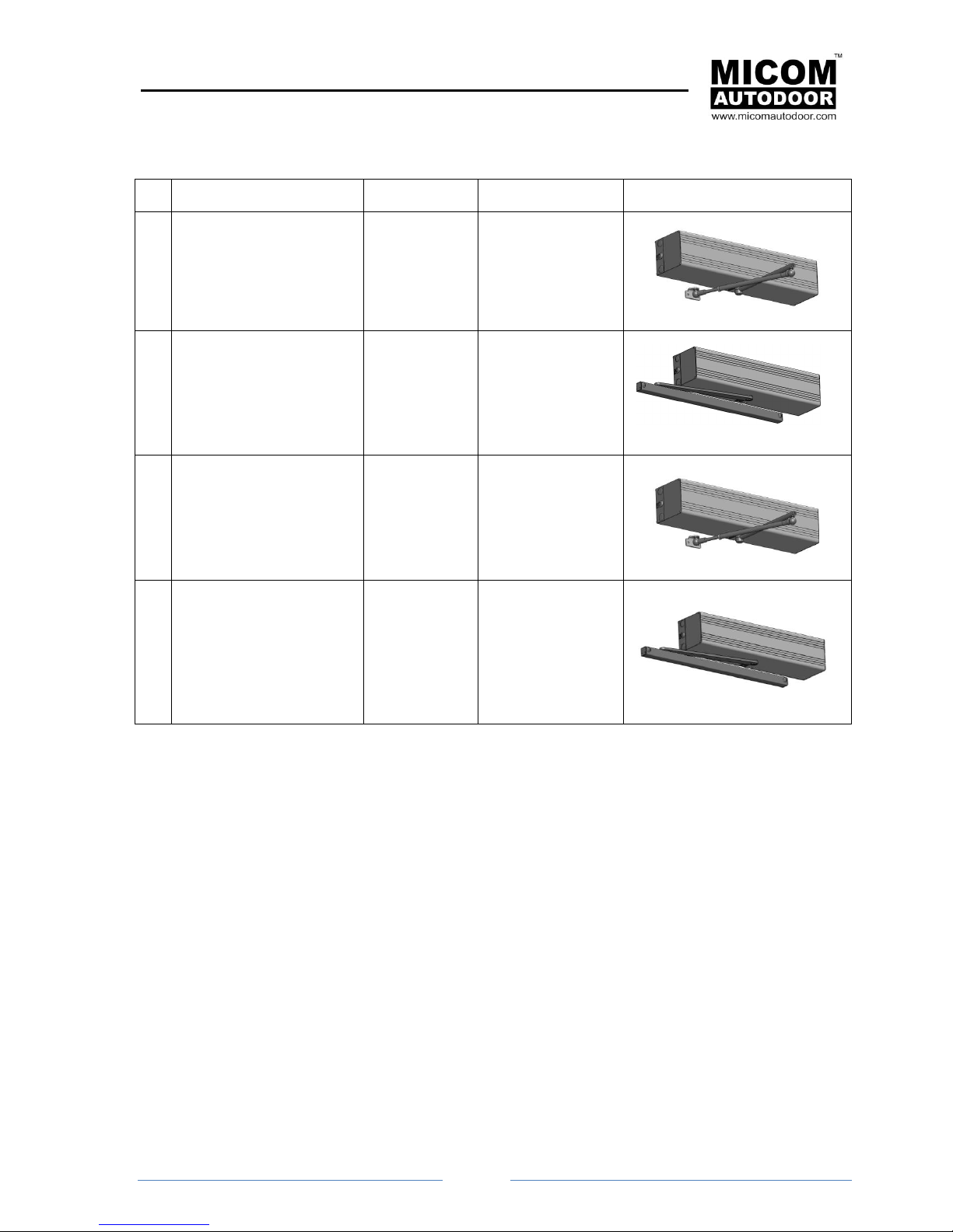
4.2 Identification of Operators
Nº
Operators
Reference
Description
Image
A1
MICOM SWING
SW-Push
2002279
Operator for swing
doors with
articulated arm
A2
MICOM SWING
SW-Pull
2002280
Operator for swing
doors with sliding
arm
A3
MICOM SWING
SWSP-Push
2002281
Operator for swing
doors with
articulated arm and
incorporated closing
spring
A4
MICOM SWING
SWSP-Pull
2002282
Operator for swing
doors with sliding
arm and
incorporated closing
spring
Page 12
MICOM SWING SW & SWSP
Installation Manual
Page
12
5. INSTALLATION OF THE OPERATOR
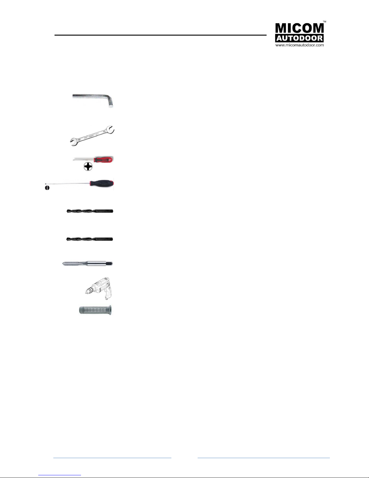
5.1 Preperation - Required tools
Allen key. Sizes:
● 2’5
● 3
● 5
Spanner. Sizes:
● 13
● 14
Phillips screwdriver. Sizes:
● #0
● #1
Flat Screwdriver. Sizes:
● 2
Drill bit for wall/concrete. Sizes:
● 8
● 6
Drill bit for metal. Sizes:
● 5
● 4
Plug for metric thread:
● M6
Drill
Wall plug
Page 13
MICOM SWING SW & SWSP
Installation Manual
Page
13
5.2 Prepare Operator
● Unpack the operator with care.
● Remove the central screw from the front cover
1. Remove the front cover with care
2. Loosen the screw at the end of the reel so that this can move or turn easily.
Remove screw with
2’5 Allen key
Loosening with Allen
key 3
Page 14
MICOM SWING SW & SWSP
Installation Manual
Page
14
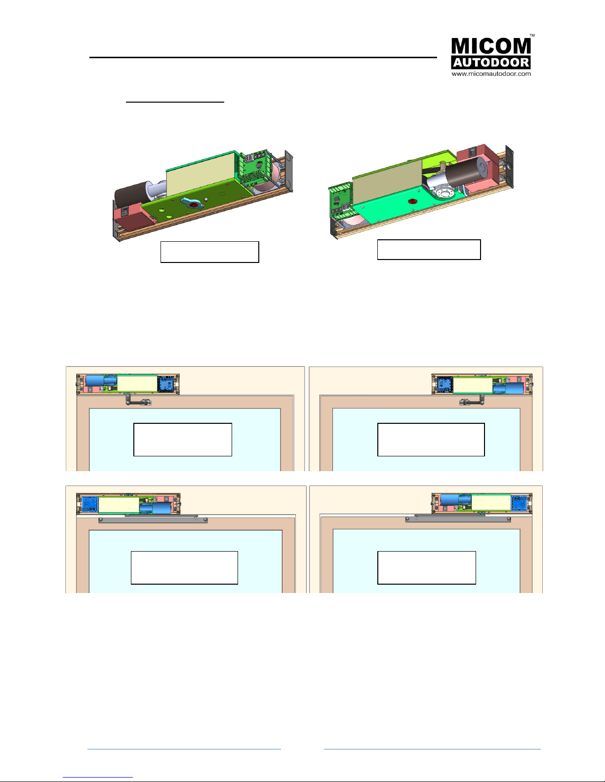
3. Orientate the operator. Before fixing the operator to the door frame or wall, we should study
the orientation of the same, which can be: Normal or Reversed.
The orientation of the operator depends on the following factors:
opening direction
placement (this can be on the framework or on the door panel)
situation of the door (right or left)
Installation Examples
The operator is totally reversible and therefore it can be adapted to any of the previous factors without
needing to change the mechanics or the programming. It is sufficient to turn it around to orientate it in
one direction or the other.
Therefore, if by mistake the operator was installed upside down. Upon giving the order to open it
actually closes, by simply changing the orientation we can solve the problem.
Normal Position
Reverse Position
Normal Position
(Left Push)
Reverse Position
(Right Push)
Normal Position
(Right Pull)
Reverse Position
(Left Pull)
Page 15
MICOM SWING SW & SWSP
Installation Manual
Page
15
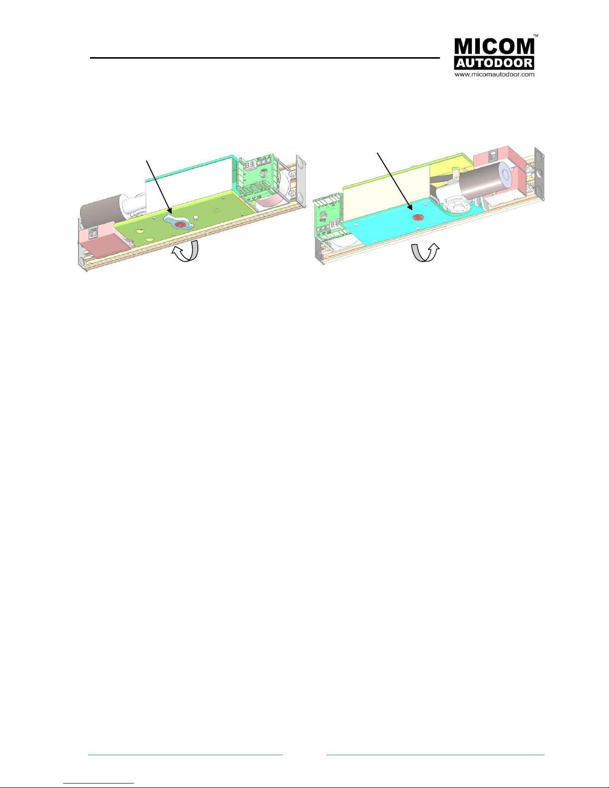
There are two ways to know how to orientate the operator:
A. By Motor Pivot Direction:
A. One method consists of turning the motor’s pivot manually. We can use the operator arm
B.
B. Turning the motor’s pivot manually, we can use the operator arm to assist us. By turning
motor pivot in both directions, using the operator arm to assist in this moment by hand, we
can see that the motor turns with no resistance in one direction; while on the other hand,
turning the motor in the other direction needs greater force. In summary:
Low resistance when turning corresponds to the opening direction of the door.
High resistance when turning corresponds to the closing direction of the door.
6. FIXING OPERATOR
6.1 Introduction
In order to fix the operator to the door frame, a template is provided with indication as to where the
fixture holes should be. There are 6 holes represented (4 fix the operator to the frame and 2 fix the
operator arm to the door).
These 6 holes are the minimum required that must be used to fix the mechanism correctly.
Before proceeding to fix the operator we recommend keeping the following advice in consideration:
● If the operator is fixed to a thin metal surface (less than 10mm thickness) it is strongly advised
to use threaded screws metric size M6 instead of self-tapping screws.
● If the operator is fixed onto a hollow brick it is strongly advised to use a plastic wall plug and a
threaded rod metric size M6.
Motor Pivot Direction
Motor Pivot Direction
Page 16
MICOM SWING SW & SWSP
Installation Manual
Page
16
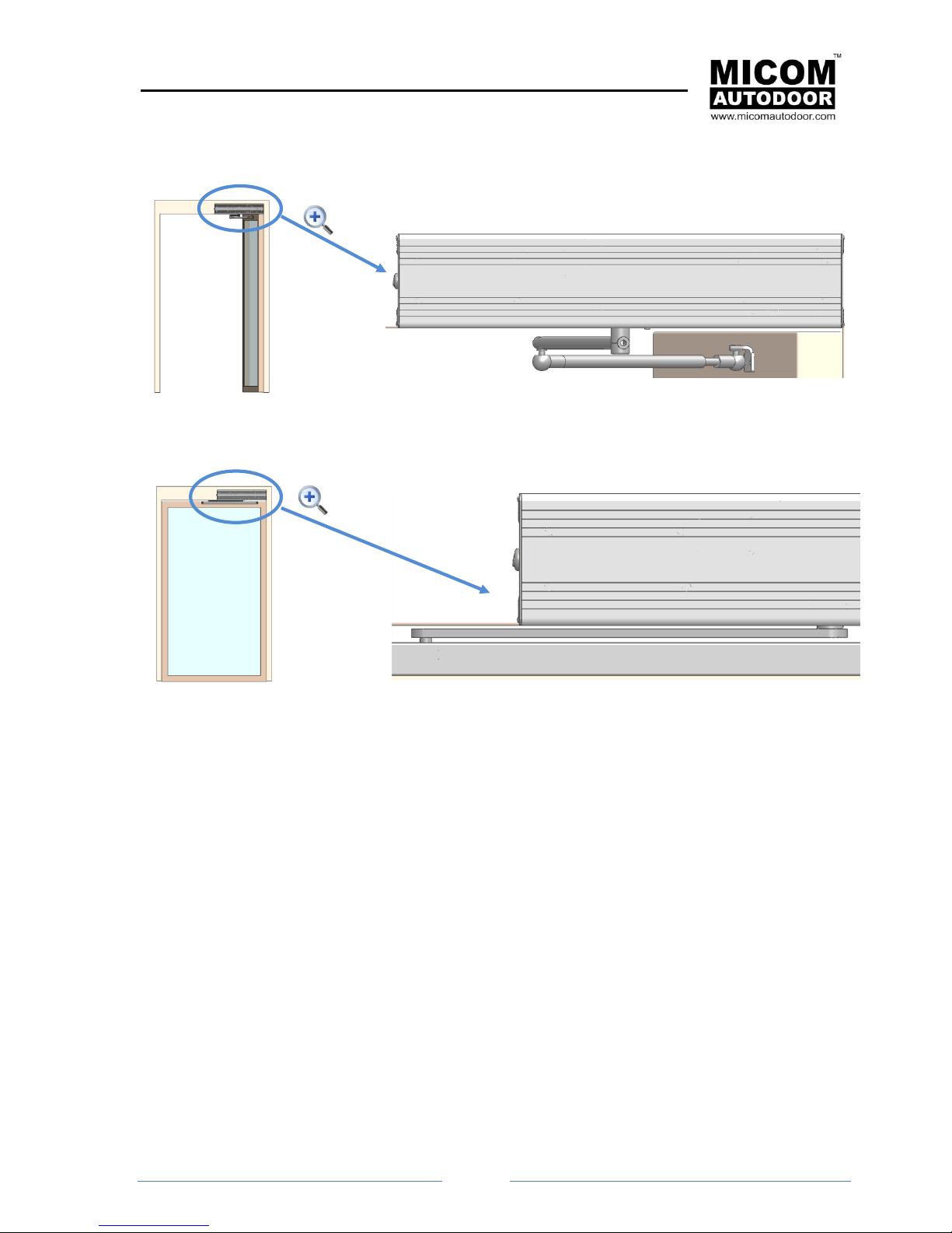
● When the operator with an articulated arm (push) is fixed, a security distance should be used
so that the arm does not hit against the door frame.
● When installing and operator with a sliding arm (pull), leave a safe distance so that the arm
does not knock against the door panel.
Important notice: In the event of using less fixture points than those required, or not following the
previous advice, there is a risk of the mechanism coming unfixed or falling. This would put the people
using the automatic door in danger.
Clearance or security distance
with respect to the door frame.
Security distance = 11mm
Clearance or
security
distance with
respect to the
door panel
(max. 9mm)
Page 17
MICOM SWING SW & SWSP
Installation Manual
Page
17
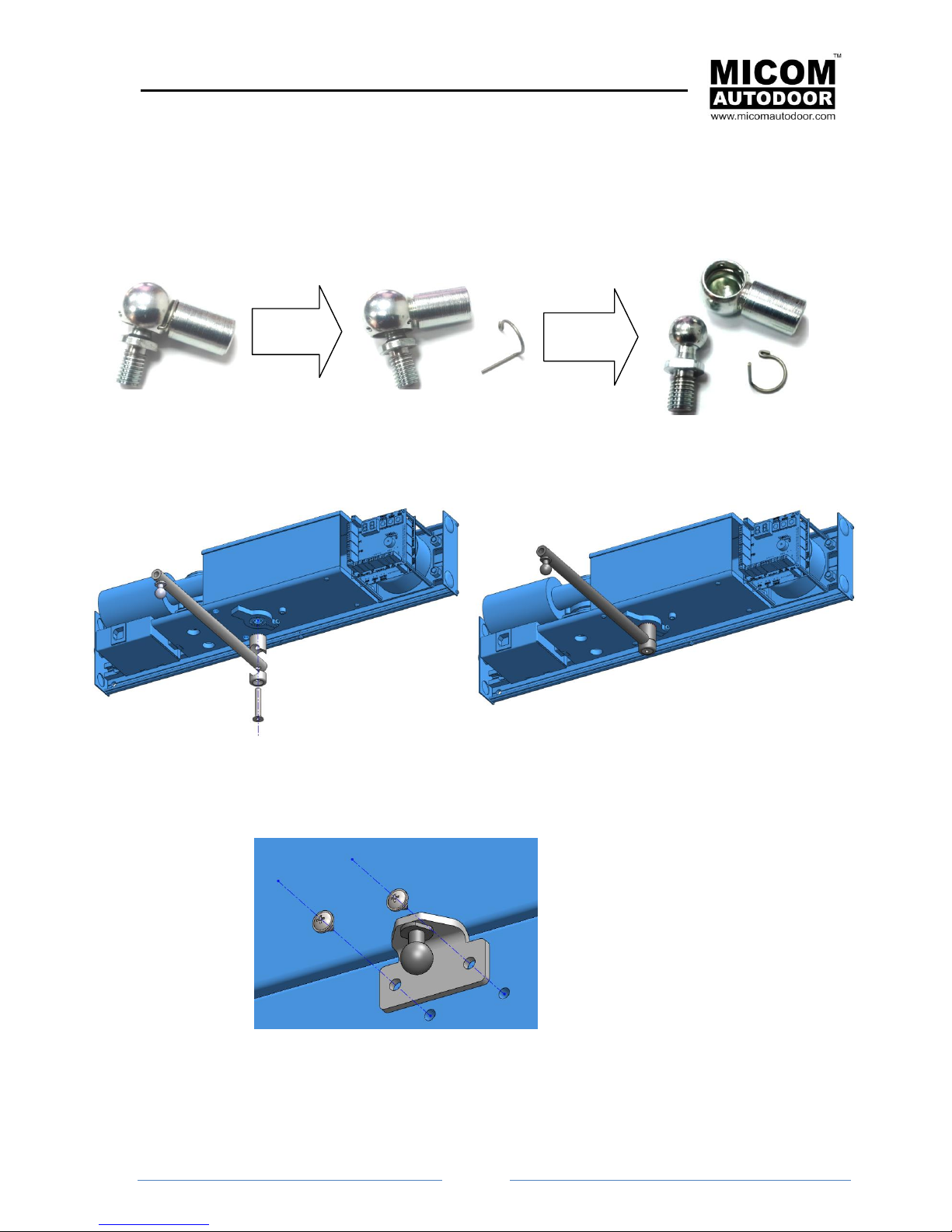
6.2 Fix and Adjust to Articulated (Push) Arm
In order to fix and adjust the articulated arm:
1. Separate the two parts of the arm joints. In order to separate them, you will have to remove
the security ring.
2. Screw in the upper part of the arm.
3. Make two holes in the door by following the indications as shown in drawings.
Remove
circlip
Separate
parts
Page 18
MICOM SWING SW & SWSP
Installation Manual
Page
18
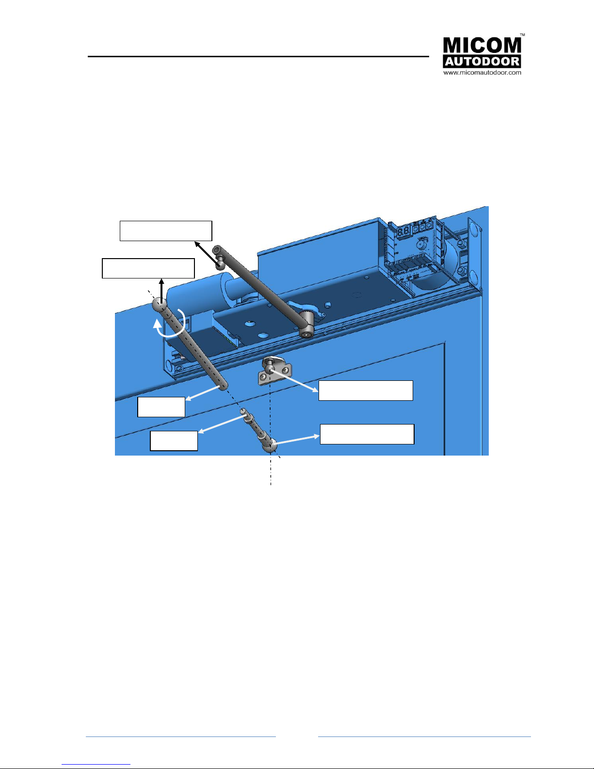
4. Introduce joint 1 (socket) into joint 2 (plug) (see the following figure).
5. Join “Part A” with “Part B” (see following figure).This will be achieved by screwing it in.
6. Close the door and keep it closed until the arm has been installed.
7. By turning “Part A” we can lengthen or shorten the arm if we turn it in one direction or the
other. Turn “Part A” so that joint 4 (socket) meets up with joint 3 (plug) (see the following
figure).
8. Then place each joint into its security ring.
9. Open and close the door and check that it is working correctly.
Note: Adjust the end of the rod (for more details see section “6.5.-ADJUST OPENING LIMIT”).
Label 2 (plug)
Label 1 (socket)
Part B
Part A
Label 4 (plug)
Joint 3 (socket)
Page 19

MICOM SWING SW & SWSP
Installation Manual
Page
19
6.3 Fixing Slide Arm (Pull)
In order to fix and adjust the sliding arm:
1. Remove the end covers to be able to work freely.
2. Introduce Part_B into Part_A, for one of its extremes.
3. Following the drawing instructions Make 2 holes in the door and fix the arm to the door panel.
4. With the door in the closed position. Fix Part_B of the arm to the motor pivot. Put the covers
back on.
Part_A
Part_B
Part_A
Part_B
Page 20

MICOM SWING SW & SWSP
Installation Manual
Page
20
6.4 Set up of the Tension Spring
MICOM SWING SPSW has a door-closing system. In order for this to function perfectly, the tension
spring must be pre-loaded. This load can be higher or lower depending upon the size/weight of the
door panel or the clients’ requirements. To load the spring:
1. Make sure the operator is not connected to the electricity supply. If it is, take the plug out from
the feed source.
2. Remove the operator arm; it will be sufficient to remove the screw that links the arm to the
motor pivot.
3. Loosen the lever screw so that this can move and turn easily.
4. Press the ‘-TEST’ button and without letting it go, connect the electricity supply to the operator
using the 3pin plug. If it has been done correctly the letter F will appear, followed by the
number 0 on the screen.
5. On the screen the letter F appears followed by the number 0, which represents the force
loaded on the spring; value 0 is the lowest. If we press +RESET, the number will increase and
the motor will start to turn. As the motor turns the spring will be charged. The higher we
increase the value, the more the spring will be charge. Please see the following table how
value F relates to the spring force.
“F” Value
Force loaded on the spring
Recommendation
0
0
Invalid
1
9Nm
Doors up to 50Kg
2
13Nm
Doors up to 100Kg
3
18Nm
Doors up to 150Kg
4
22Nm
Doors up to 180Kg
Loosen with Allen
key 3
Keep pressing before
and after connecting
the operator to the
electrical supply
Page 21

MICOM SWING SW & SWSP
Installation Manual
Page
21
6. After assigning a value to F, wait for the motor to stop turning (normally no more than a
minute). When the motor stops, close the door and fix the arm to the motor pivot.
7. Then press “-TEST” once more to save the changes and to check that the letter “F”
disappears from the screen.
8. Disconnect the operator from the electricity supply
9. Open the door manually and check that it closes by itself.
10. Adjust the end of the run.
6.5 Adjusting Opening Limit
Steps to follow:
1. Loosen the screw for the limit lever so that it can move and turn freely.
2. Open the door to the desired opening point. If the operator is spring closing, it is necessary to apply
either a door stopper or something similar so that the door stays open, until finished adjusting the
limit.
3. Turn the lever until the final limit is obtained.
Loosen with Allen
key 3
Page 22

MICOM SWING SW & SWSP
Installation Manual
Page
22
4. Tighten the lever screw so that it is fixed firmly to the motor pivot.
7. OPERATION OF MICOM SWING SW & SWSP UNIT
7.1 Start Up and Self Learning
IMPORTANT NOTICE: When the MICOM SWING SW & SWSP system starts up for the first time, the
self-adjustment process will start for the system. This process will carry out an opening and closing
cycle to find the actual length of the door stroke.
It is very important to allow the door to carry out these cycles freely, i.e. with no obstacles. It is
therefore recommended that no-one goes near the door. If the panel has any obstruction during the
learning cycle, the whole process should be re-started via the RESET on the control unit (see section
12.2.5 - for more information).
During the Self-learning process, the automatic door will automatically carry out the following actions:
1. Prior to starting, ensure that the operator selector has been connected, as well as the electricity
supply, transformer, motor and the control unit.
2.Plug in connector to the supply situated to the right of the Control Unit and place the operator
selector on any function, except that of closing or manual.
3.The door opens slowly until it reaches its opening position.
4.The door closes slowly until it reaches its closing position.
5.From here on the door will work normally, although the first movements will often brake early. As the
operator continues with the closing and opening cycles, the door will gradually find the most efficient
braking point.
This process is only carried out on the first occasion when the automatic door is activated and
every time the RESET is used. (see section“12.2.5.-”).
If for any reason you are unable to carry out the Self-learning process correctly, you must go
through the process again through “RESET” on the Control Unit.
Tighten with Allen
key 3
Page 23

MICOM SWING SW & SWSP
Installation Manual
Page
23
Every time that important changes take place on the automatic door, such as: change of
position of the stoppers, change to the size of the panels or change to the weight of the
panels, in these cases you always have to do a “RESET” in order for the Control Unit to adapt
to the changes.
After carrying out a “RESET” on the Control Unit, as well as re-starting the Self-learning, the
parameters will be cancelled off and will return to the factory settings. There are certain
parameters that will not cancel off after a “RESET”, such as: the number of cycles and the
function time.
7.2 Normal Function
In order to ensure that the System is working correctly, check the “POWER ON”, located on the
Control Unit is always switched ON.
When the Control Unit receives an impulse to open (for example, a movement sensor, an emergency
command or switch/sensor) the “INPUT ON” on the display screen will activate. The motor will then
start to turn and provide movement to the automatic door panels to open.
When there is no signal to open, the motor will turn in reverse direction until the door is fully closed.
When it receives the signal to stop (by means of pressing the emergency stop button) the door will
brake and will remain still while the signal to stop is in place.
POWER ON
INPUT ON
Page 24

MICOM SWING SW & SWSP
Installation Manual
Page
24
7.3 Electrical Fault
If the operator is equipped with a battery system (optional) and there is a cut in the electricity supply,
the door will continue to function normally until the battery is dead.
Once the battery is almost empty, the automatic door will cease to function until the general electricity
supply returns or until the “Night Bank” or Night Switch is activated.
If the “Night Bank” (switch) comes into action, it will activate the battery system and the motor will
open/close the door.
When the electricity supply fails and if the operator is not equipped with a battery system:
- with the MICOM SWING-SW model will stop working.
- with the MICOM SWING-SWSP model the door will only close.
7.4 Errors
A case could occur where the system has suffered a problem and therefore would cease to function
correctly, e.g. in the event of a power cut or when the automatic door hits a pedestrian.
In these cases, the automatic door will give both a visual and acoustic signal to indicate what error
has taken place (for more information see section”14. PROBLEM SOLVING. ERROR TABLE”).
Page 25

MICOM SWING SW & SWSP
Installation Manual
Page
25
8. CONNECTIONS
8.1 Connection to the Electrical supply
The control unit can work at 230V or 110V, depending on client requirements. The feed power is 230V
when it leaves the factory but the system can be configured to work at 110V; only a small modification
has to be carried out inside of the feed supply (contact us for more details).
The control unit is compatible with frequencies 50Hz and 60Hz.
Power connection is by way of 3 pin connector plug located in the upper part of the operator (see the
following image). It is compulsory to earth the power supply in order to avoid problems when the
product is working and also to protect users from dangerous situations.
ATTENTION!!
Be extremely careful
with this
connection. An error
can damage the
Control Unit and
cause serious injury
or death.
Live
Earth
Neutral
Page 26

MICOM SWING SW & SWSP
Installation Manual
Page
26
8.2 Internal Basic Connections
Connection from the transformer to the feed supply.
The connection from the transformer to the supply should be done with an 8-wire cable. This
connection takes place in the factory and the technician should only have to do it in the event of a
breakdown or when having to replace components (see the following figure for more details).
Connection from the supply to the control unit.
The connection from the supply source to the control unit will be done with a 4-wire cable. This
connection will be done in the factory and the technician should only have to do it in the event of a
breakdown or when having to replace components (see the following figure for more details).
Connection from the motor to the Control Unit
The connection from the motor is done with two cables: one of 2 wires (feed) and the other 4 wires
(position coder). This connection is done in the factory and the technician should only have to do it in
the event of a breakdown or when having to replace components (see the following figure for more
details).
Connection:
Motor / Control Unit
Connection:
Transformer / Power Supply
Connection:
Power Supply / Control Unit
Page 27

MICOM SWING SW & SWSP
Installation Manual
Page
27
9. Connection of other Components
The EMICON card provides the function of inter-connecting the Control Unit to the various
components: emergency battery, sensors, emergency button, control system, selectors, etc.
The following are the connections:
P2: 24Vdc Output. 0,3A max
P3: Security sensor monitor (TEST)
P4: Emergency Stop
P13: Emergency Open/Close
P11: Selector B
P7: Selector A
(It is located
on the side of the
operator)
P6:
24Vdc bolt
(Lock)
P9: Internal Sensor
P10: Closing safety
Sensor (Security 1)
P8: External Sensor
P5:
Night
Bank/
Switch
P14: Opening safety
Sensor (Security 2)
P12:
12Vdc bolt
(Lock)
P1: Access control card ST-500
Page 28

MICOM SWING SW & SWSP
Installation Manual
Page
28
9.1 P1 Connector. Access control card ST-500 connection
The P1 connector links to the access control card, which allows control of the opening and closing of
the door by means of remote controls, proximity key, tag, etc.
9.2 P2 Connector. 24V output
The P2 connector has a power supply output of 24V. This output can be used when additional
components are required to be connected to the automatic door, e.g. access control systems via
password, etc.
Consider the consumption required by the component being connected as the maximum current is
300mA.
Access control
card ST-500
Page 29

MICOM SWING SW & SWSP
Installation Manual
Page
29
9.3 P3 Connector. Monitoring output (Security Sensor Monitor)
The P3 connector is a communication output used by some presence detectors. It will check if the
sensor is working correctly with this communication and therefore increasing the level of security for
the automatic door (EN16005).
This connection takes place between the P3 connector and the sensor input, which is usually called
“MONITORING”, or supervision input”.
The P3 connector output is 24V and its polarity must be taken into consideration as shown in the
following image:
Page 30

MICOM SWING SW & SWSP
Installation Manual
Page
30
NOTE: The Control Unit does not have the Monitoring function activated when it leaves the factory.
In order to activate it, parameters 18, 19 or 35 need to be programmed - depending upon which
sensor we want to Monitor in the Control Unit (see section “12.-PROMGRAMMING OF THE
CONTROL UNIT”).
Parameter 18 activates the Monitoring of the sensors connected to P10 (Closing Safety), Parameter
19 P9 (internal sensor).
Parameter 35 activates the Monitoring of the sensors connected to P14 (Opening Safety).
P3 is connection of the Monitoring signal of multiple sensors. i.e : safety when closing, movement or
safety when opening.
9.4 P4 Connector. Emergency Stop
The P4 connector is an input used for connection to the emergency stop device. This input is
programmed when leaving the factory to work with Normally Open contacts (NO), but can be
programmed to work with Normally Closed contacts (NC), (please see section “13 PROGRAMMING PARAMETRES” - Parameter Nº22”).
When this input is activated the door will immediately stop.
9.5 P13 Connector. Emergency Open/Close
This input is connected mainly to the fire alarm and anti-panic systems and its function is to Open or
Close the door in any situation, except when the function selector is in the position of CLOSED or
MANUAL.
This input is programmed at the factory so that it works with Normally Open (NO) contacts. The door
can open but it can be programmed to function with Normally Closed (NC) contacts, or for the door to
close (see section “13.-PROGRAMMING PARAMETRES” - Parameter Nº32”).
9.6 P5 Connector. Night Bank / Switch
Its function is to Open the door in whatever situation, including a power cut (battery optional).
In the event of a fault in the general electricity supply, this signal can open the door by making use of
an emergency battery (this battery is optional and is not included in the operator).
This input has priority over the function selector.
This input only works with Normally Open (NO) contacts.
9.7. P6 Connector. E-Lock or Automatic Bolt (Lock) 24Vdc
The P6 connector is a 24Vdc output.
NOTICE! Never go over the maximum consumption. If so the control unit will be damaged. The
maximum consumption is 7W (300mA).
Automatic alternating current bolts are not allowed; their use provokes severe damage to the control
unit. Only automatic bolts that work with direct current can be connected. Special attention should be
paid to the voltage value; in the event of placing an automatic bolt that is different from 24V, the
control unit will be damaged.
Page 31

MICOM SWING SW & SWSP
Installation Manual
Page
31
This input has 5 working modes:
Value 0 = No Lock Fitted (recommended when using Push&Go)
Value 1 = Automatic Bolt unlocked with 12/24Vdc; and locked with 0V. *
Value 2 = Automatic Bolt unlocked with 0V; and locked with 12/24Vdc. *
Value 3 = Automatic Bolt unlocked with 12/24Vdc; and locked with 0V. **
Value 4 = Automatic Bolt unlocked with 0V; and locked with 12/24Vdc. **
* It unlocks just prior to the door opening and during the first 0º~20ºof opening.
** It unlocks just prior to the door opening and during the entire process of opening/closing.
These functions are programmable in the Unit Control (see section “13.-PROGRAMMING PARAMETRES” -
Parameter Nº15).
Page 32

MICOM SWING SW & SWSP
Installation Manual
Page
32
In the event that the E-lock used should have polarity, the connection has to be carried out as follows:
Note: If the E-Lock product has no polarity, then connections are free
9.8 P12 Connector. Supply for E-Lock or automatic bolt 12Vdc (Lock)
The P12 connector has the same qualities as the P6. The only difference is that the P12 connector
works with 12Vdc voltage and therefore the automatic bolts connected in the P12 must be 12V DC.
Note: Special attention must be given to the working voltage value; in the event of placing an
automatic bolt that is different from 12 V, the control unit will be damaged.
Page 33

MICOM SWING SW & SWSP
Installation Manual
Page
33
9.9 P9 Connector. Internal movement sensor (Internal Sensor)
The P9 connector is used to connect a motion sensor.
The connector consists of 4 poles:
● Two poles are used to supply the sensor. The output is 24V DC.
● The other two poles are the input of the sensor signal, which can be: free of voltage (relay
output, no polarity) or by transistor (with polarity).
The signal input is programmed at the factory to act as a Normally Open contact. It can also be
configured as Normally Closed contact (see section “13.-PROGRAMMING PARAMETRES” Parameter Nº19).
9.10 P8 Connector. External movement sensor (External Sensor)
The P8 connector is used to connect a movement sensor.
The connector consists of 4 poles:
● Two poles are used to supply the sensor. The output is 24V DC.
● The other two poles are the input of the sensor signal, which can be: free of voltage (relay
output, no polarity) or transistor (with polarity).
The input signal is programmed from the factory to act as a Normally Open contact, although it can be
configured as a Normally Closed contact as well (see section “13.-PROGRAMMING PARAMETRES”
- Parameter Nº20”).
Page 34

MICOM SWING SW & SWSP
Installation Manual
Page
34
Its connection is identical to that of the P9 connector, except that it can be carried out in the P8
connector.
9.11 P10 Connector: Closing Safety Sensor 1 (Security 1)
The P10 connector is used to connect the security sensor (or presence sensor) which protects from
possible obstruction in the door closing movement.
The connector consists of 4 poles:
● Two poles are used to supply the sensor. The output is 24V DC.
● The other two poles are the input to the sensor signal, which can be: free from voltage (relay
output, no polarity) or by transistor (with polarity).
The signal input comes programmed from the factory to act as a Normally Closed contact, although it
can be configured as a Normally Open contact as well (see section “13.-PROGRAMMING
PARAMETRES” - Parameter Nº21”).
Page 35

MICOM SWING SW & SWSP
Installation Manual
Page
35
In the event of needing more than one security sensor with NC (Normally Closed) contacts there
needs to be a connection in series with the signal sensors, just as can be seen in the following figure:
9.12 P14 Connector: Opening Safety Sensor 2 (Security 2)
The P14 connector is used to connect the security sensor. This sensor protects from possible
collisions of door opening movement.
The connector consists of 4 poles:
● Two poles are used to feed the sensor. The output feed is 24V DC.
● The other two poles are the input of the sensor signal, which can be: free of voltage (relay
output, no polarity) or transistor (with polarity).
The signal input comes programmed from the factory to act as Normally Open contact, although it can
be configured as a Normally Closed contact as well (see section “5.3.-PROGRAMMING
PARAMETRES” - Parameter Nº33”).
Its connection is identical to that of the P10 connector except that it is carried out in the P14
connector.
Page 36

MICOM SWING SW & SWSP
Installation Manual
Page
36
9.13 P7 Connector: Selector A (Switch in three positions)
The P7 connector connects the selector on the side of the operator.
This selector has three positions, which are:
I - HOLD OPEN - This mode allows the door to stay open.
0 - MANUAL – The door will only open or close manually.
II - AUTOMATIC - This mode allows entering and exiting automatically.
The connection is carried out by a two-wire cable without polarity.
This connection is carried out in the factory and is very simple to replace if needed.
Note: If Selector B (Digital) is connected the action of this selector will be cancelled. Selector B will
have priority over Selector A.
2 Cables
Page 37

MICOM SWING SW & SWSP
Installation Manual
Page
37
9.14 P11 connector: Selector B (Digital)
The P11 connector connects a Digital Selector. In order to change the function mode of the automatic
door and keep it in its memory.
The connection is by a 4- wire cable. Please be careful in the connection because these cable hasve
polarity.
Note: Bridge P7 of the control unit must be connected (it already comes connected from the factory).
Digital Selector B
The voltage used is 5V.
Multiple selectors B (Digital) can be connected to the same Control Unit.
When this selector is connected to the Control Unit, Selector A (three position selector) becomes
deactivated and stops working.
If multiple Selector B (Digital) are required, the following configuration of Selector B is necessary:
1.- Open the cover to access to the electronic board. For this you will have to remove 4
internal screws.
2.- Once the screws have been removed, remove a “Bridge” called P5.
3.- This procedure should be carried out on all the selectors connected to the operator
EXCEPT in one of them. This should be the one furthest away from the operator. If, for
example, we have an operator with three connected selectors, we should remove the “bridge”
to the two selectors nearest to the operator; the selector which is the furthest away, will not be
modified.
NOTICE! Selector B (Digital) must be connected to the correct Connector. If connected to
wrong connector (for example, sensor or security sensor), it will be irreversibly damaged and
could also damage the Control Unit.
Page 38

MICOM SWING SW & SWSP
Installation Manual
Page
38
Operating Modes
The Selector B (Digital) has 6 buttons, giving various working modes. It also has 6 LED indicators that
show the current working mode. All of the working modes available are as follows:
“Close” mode. This mode allows us to close the door (locked if it has an electro-
magnetic lock). In this mode the emergency opening system (battery) will remain
disconnected.
“Exit only” mode. This mode only allows to exit.
“Entre only” mode. This mode only allows Entry only.
“Automatic” mode. This mode allows to enter and exit.
“Permanently open” mode.
“Manual” mode. In this mode, the operator does not act on the door and allows it to
open or close manually.
Memory Retension
Another function that Selector B (Digital) offers is to save the setting in the memory even after a
power cut. There are 2 possible working modes.
“NO MEMORY” mode. In this programming mode the state of the selector is NOT saved in the
memory in the event of a power cut. When the power resumes the automatic door will always be reestablished in the “close” working mode.
In order to activate the NO MEMORY mode, keep the ‘close’ button pressed down for 5 seconds.
“WITH MEMORY” mode. In this programming mode, the state of the selector is saved in the
memory when there is a power cut and therefore when the electric supply returns, the operator will
Page 39

MICOM SWING SW & SWSP
Installation Manual
Page
39
resume the same state as to prior to the power cut.
In order to activate the WITH MEMORY mode, the ‘Automatic’ button must be pressed down for 5
seconds.
Note: This programming mode has been implemented by the factory.
10. DOULE DOOR OPERATION (DUAL)
Installation of Double Swing operation:
● Two operators are used in double doors - one for each door. Install both operators (for more
information see section 5.-OPERATOR INSTALLATION).
● Place a bridge P17 in each of the control units (this comes installed from the factory).
● Connect the TX signal from the P11 connector from operator 1 with the TX signal connector
P11 of operator 2. Connect the RX signal of the P11 connector of operator 1 with the RX
signal of the P11 connector of operator 2.
● Check the resistance value with a polimetre (Ω) between TX and RX. If everything is correct,
you should obtain a value between 55 and 65 Ω. If this is not the case, check that a bridge
has been done on P17. If you continue to receive an incorrect value, remove the bridge
situated in the B selectors (digital).
● Go into programming and assign the following values to the Master door:
● Parameter 37 = 1
● Go into programming and assign the following values to the Slave door:
● Parameter 37 = 2
● It may be required to alter the following parameters relating to the double doors:
● Parameter 38, Parameter 41, Parameter 42.
Page 40

MICOM SWING SW & SWSP
Installation Manual
Page
40
11. PROBLEMS
11.1 Interference
NOTICE: In certain automatic doors installations it could require to wire cables together. This should
never be done. It is important to keep sensor and function selector cables apart from mains power
cables. If wired together, it could make the microprocessor function incorrectly in either the long term
or short term, resulting in irreversible damage and break down.
If it is necessary to pass all cables through the same pipe, the cables belonging to the automatic door
must be shielded and earthed at both ends. Always try to keep the power cables (230V or 110V) away
from the signal cables (photocell, selector, radar, motor, etc.).
The function selector cable and the power supply cables (230V or 110V) should never be bound
together and must always where ever possible be separated.
Page 41

MICOM SWING SW & SWSP
Installation Manual
Page
41
12. PROGRAMMING THE CONTROL UNIT
12.1 Introduction
The Control Unit has an area dedicated to programming of distinctive parameters of the automatic
door, such as: speed, opening time, brake power, etc.
The programming is carried out via a LED display and 3 buttons, as shown in the following image.
12.2 Programming Menu
12.2.1 Enter into the programming menu
To get into the programming menu press the “ENTER PROG.” for approximately 5 seconds.
While pressing “ENTER PROG.”, the Control Unit will make a sound and the display screen will show
the letter “P”, once every second.
Once 5 seconds have passed, a “00” message will show on the screen and this will indicate that the
programming menu is now active. Stop pressing “ENTER PROG.”.
This operation should only be carried out after the automatic door has stopped.
12.2.2 Modify the programming parameter
When in the programming menu, modify the programming parameters as follows:
- Initially the display will show two digits that go from “00” to “50”, this represents the parameter
we wish to modify (see section “5.3.-Programming parameters”).
Pressing “ENTER”, it will show the value of the parameter which is represented by “=”,
followed by the number representing this value, e.g. “=0”.
Every time press “ENTER” it will go between the change parameter mode and change
parameter value mode.
- When the buttons “+” and “-” are in the change parameter mode, select the parameter
required. When in the change of parameter value mode, these buttons will increase or
decrease this particular value.
DISPLAY
Buttons
Page 42

MICOM SWING SW & SWSP
Installation Manual
Page
42
12.2.3 Exit Programming Menu & Saving Modifications
In order to exit the programming menu and save all the changes carried out, you must do the
following:
● Go into the “00”parametre
● Press “ENTER”
● Press “+”
12.2.4 Programming Example
We wish to change the option how the emergency stop works and we want this function to act as
normally closed contact. In order to do this we need to follow the following steps:
● If the door is working, we have to wait until it finishes opening or closing. In order to avoid
possible accidents while we reprogrammed, we recommend putting the function selector at
“door closed” or “door open”.
● Hold the “ENTER” button for 5 seconds until the display screen shows the “00” message.
● Now press 22 times on the “+”, that is until the number 22 appears on the display (if we look
at the table from section “5.3.- Programming parameters”, we will see that 22 represents the
emergency stop parameter).
● Press “ENTER”. The display screen will show the “=0” value which indicates that the
emergency stop is configured to work as a normally open contact.
● Press “+”. The display screen will show the “=1” value which indicates that the emergency
stop is configured to work as a normally closed contact.
● Press “ENTER”. The display screen will show the value “22”.
● At this moment, the emergency stop has been programmed as a normally closed contact.
Now we are need to Exit the programming and save the data:
● Press “-“ 22 times, i.e. until the value of “00” appears on the display screen.
● Press “ENTER”.
● Press “+”.
Page 43

MICOM SWING SW & SWSP
Installation Manual
Page
43
2. Press and hold “ENTER PROG.”
1. Press and hold “+ RESET”
3. If done correctly, 3 red lines will blink on the
display. Press and hold both buttons until sound
signal disappear (5 seconds approx.).
12.2.5 RESET of the programming
The control unit retains programming parameters in its memory and also other important details such
as door operation setting from the learning process as well as braking adjustments etc…
This data can be reset to factory default setting.
The RESET of the Control Unit can be done in two ways:
First (recommended)
● Remove the power supply from the Control Unit (if so, also the battery).
● Press the “RESET” button and keep it pressed, then re-insert the power supply to the Control
Unit.
● Wait 5 seconds until the Control Unit stops beeping.
● Stop pressing the “RESET” button.
Second
● Press the “+ RESET” button and then “ENTER PROG.” and maintain them both pressed for
5 seconds.
Page 44

MICOM SWING SW & SWSP
Installation Manual
Page
44
13. PROGRAM PARAMETERS
Parameter
Description
Adjust
Value
Factory
Setting
00
Exit programming
01
Display screen rotation
From 0 to 2
0
Value 0 = Automatic
Value 1 = Normal
Value 2 = Reserve
02
Automatic Closing Timer
From 1 to 9
2
Value 1 = 1 second
Value 2 = 2 seconds
Value 3 = 3 seconds
Value 4 = 4 seconds
Value 5 = 5 seconds
Value 6 = 10 seconds
Value 7 = 20 seconds
Value 8 = 30 seconds
Value 9 = 60 seconds
03
Opening Speed
From 0 to 9
6
Value 1 = 15º/s
Value 2 = 25º/s
Value 3 = 35º/s
Value 4 = 45º/s
Value 5 = 50º/s
Value 6 = 55º/s
Value 7 = 60º/s
Value 8 = 65º/s
Value 9 = 75º/s
04
Closing Speed
From 0 to 5
2
Value 1 = 15º/s
Value 2 = 25º/s
Value 3 = 35º/s
Value 4 = 45º/s
Value 5 = 50º/s
05
Dynamic Opening Force
From 1 to 9
9
Value 1 = Even Minimum Strength
Value 9 = Even Maximum Strength
06
Dynamic Closing Force
From 1 to 9
9
Value 1 = Even Minimum Strength
Value 9 = Even Maximum Strength
Page 45

MICOM SWING SW & SWSP
Installation Manual
Page
45
07
Opening Deceleration
From 0 to 9
5
Value 0 =Gradual Deceleration
Value 9 = Rapid Deceleration
08
Closing Deceleration
From 0 to 9
0
Value 0 = Gradual Deceleration
Value 9 = Rapid Deceleration
09
Static Opening Force
From 0 to 4
0
Value 0 = 0 N
Value 1 = 10 N
Value 2 = 20 N
Value 3 = 30 N (recommended in areas of high winds)
Value 4 = 40 N ((recommended in areas of high winds)
10
Static Closing Force
From 0 to 4
1
Value 0 =0 N (recommended when using the Push&Go)
Value 1 = 10 N
Value 2 = 20 N
Value 3 = 30 N (recommended in areas of high winds)
Value 4 = 40 N (recommended in areas of high winds)
11
Push & Go
0 or 5
0
Value 0 = Deactivated
Value 1 = Activated in 2º
Value 2 = Activated in 3º
Value 3 = Activated in 5º
Value 4 = Activated in 9º
Value 5 = Activated in 15º
12
Acoustic Warning
0 or 1
1
Value 0 = Deactivated
Value 1 = Activated
13
Brake Point on Opening
From 0 to 6
2
Value 0 = At 0º of the total opening
Value 1 = At 5º of the total opening
Value 2 = At 10º of the total opening
Value 3 = At 15º of the total opening
Value 4 = At 20º of the total opening
Value 5 = At 25º of the total opening
Value 6 = At 30º of the total opening
14
Brake Point on Closing
From 0 to 6
2
Value 0 = At 0º of closing (this value is only available if there is
no automatic bolt)
Value 1 = At 5ºof closing (this value is only available if there is no
automatic bolt)
Page 46

MICOM SWING SW & SWSP
Installation Manual
Page
46
Value 2 = At 10º of closing
Value 3 = At 15ºof closing
Value 4 = At 20ºof closing
Value 5 = At 25º of closing
Value 6 = At 30º of closing
15
Electromagnetic Lock
From 0 to 4
1
Value 0 = No Lock Fitted (recommended when using Push&Go)
Value 1 = Automatic Bolt unlocked with 12/24Vdc;
and locked with 0V. *
Value 2 = Automatic Bolt unlocked with 0V;
and locked with 12/24Vdc. *
Value 3 = Automatic Bolt unlocked with 12/24Vdc;
and locked with 0V. **
Value 4 = Automatic Bolt unlocked with 0V;
and locked with 12/24Vdc. **
* It unlocks just prior to the door opening and during the first
0º~20ºof opening.
** It unlocks just prior to the door opening and during the entire
process of opening/closing.
16
Electromagnetic Lock Release Force
From 0 to 4
1
Value 0 = 10N
Value 1 = 15N
Value 2 = 20N
Value 3 = 25N (recommended in areas of high winds)
Value 4 = 30N (recommended in areas of high winds)
17
Acoustic Warning prior to Closing
0 or 1
0
Value 0 =Deactivated warning
Value 1 = Activated warning
18
Safety Sensor in Monitoring Mode (Closing side)
0 or 1
0
Value 0 =Monitoring Mode deactivated
Value 1 =Monitoring Mode activated
19
Internal Activation Sensor / Device Input
From 0 to 2
0
Value 0 = NO (Normally Open).
Value 1 = NC (Normally Closed).
Value 2 = Bi-stable.
20
External Activation Sensor / Device Input
0 or 1
0
Value 0 = NO (Normally Open).
Value 1 = NC (Normally Closed).
Page 47

MICOM SWING SW & SWSP
Installation Manual
Page
47
21
Safety Sensor Input (Closing Side)
0 or 1
1
Value 0 = NO (Normally Open)
Value 1 = NC (Normally Closed)
22
Emergency Stop Input
0 or 1
0
Value 0 = NO (Normally Open)
Value 1 = NC (Normally Closed)
23
NIGHT BANK / Switch
0
Value 0 = Emergency Opening Mode NO (Normally Open)
24
Low Energy System (Low Kinetic Energy)
From 0 to 6
0
Value 0 = System deactivated.
Value 1 = Activated. Weight of the lower panel or equal to 50Kg.
Value 2 = Activated. Weight of the lower panel or equal to 60Kg.
Value 3 = Activated. Weight of the lower panel or equal to 70Kg.
Value 4 =Activated. Weight of the lower panel or equal to 80Kg.
Value 5 = Activated. Weight of the lower panel or equal to 90Kg.
Value 6 =Activated. Weight of the lower panel or greater than
90Kg.
25
Acoustic warning at the entrance
From 0 to 3
0
Value 0 =Deactivated warning.
Value 1 =Warning lasting 1 second.
Value 2 =Warning lasting 2 seconds.
Value 3 =Warning lasting 3 seconds.
26
Battery Monitoring
From 0 to 2
0
Value 0 = No Battery.
Value 1 =Monitoring Activated
Value 2 = Monitoring Deactivated
27
Reserved
Not available
28
Closing Force after Deceleration
From 0 to 5
1
Value 0 = Low
Value 1 =Medium-Low
Value 2 = Medium
Value 3 = Medium-High
Value 4 = High (recommended in areas of high winds)
Value 5 = Very High (recommended in areas of high winds)
29
Opening Force after Deceleration (motor damping effect)
From 0 to 5
2
Value 0 = Low (recommended when using Push&Go system)
Value 1 = Medium-Low
Value 2 = Medium
Value 3 = Medium-High
Page 48

MICOM SWING SW & SWSP
Installation Manual
Page
48
Value 4 = High (recommended in areas with high winds)
Value 5 = Very High (recommended in areas with high winds)
30
Lock Delay
From 0 to 1
0
Value 0 = 0,5 second
Value 1 = 1 second
Value 2 = 2 second
Value 3 = 3 second
Value 4 = 4 second
31
Interlock Mode
From 0 to 1
0
Value 0 = Deactivated
Value 1 = Activated
32
Emergency Open/Close Input
From 0 to 3
0
Value 0 = Emergency Opening Mode NO
Value 1 = Emergency Opening Mode. NC
Value 2 =Emergency Closing Mode. NO
Value 3 =Emergency Closing Mode. NC
33
Safety Sensor Input (Opening Side)
From 0 to 1
0
Value 0 = NO Door stops on detection
Value 1 = NC Door stops on detection
Value 2 = NO Door opens slowly on detection
Value 3 = NC Door opens slowly on detection
34
Open Limit Prior to Physical Stop
From 0 to 1
0
Value 0 = Deactivated
Value 1 = Activated
35
Safety Sensor Monitoring Mode (Opening Side)
0 or 1
0
Value 0 = Monitoring deactivated
Value 1 = Monitoring activated
36
Selector B (Digital) SLD-5 Monitoring Mode
0 or 1
0
Value 0 = Monitoring deactivated
Value 1 = Monitoring activated
37
Double Door (Dual) Function
From 0 to 2
0
Value 0 = Not defined (Single door)
Value 1 = Master
Value 2 = Slave
38
Double Door Closing Sequence
From 0 to 2
0
Value 0 =Both doors open at the same time.
Value 1 = The master door opens first and closes after the slave
door.
Page 49

MICOM SWING SW & SWSP
Installation Manual
Page
49
Value 2 = The master door will open before the slave door and
they close at the same time
39
Function of the Channel 2 receptor
From 0 to 2
0
Value 0 =Close the door immediately
Value 1 = Activates and deactivates the Push & Go (one beep
confirms the activation; two beeps the deactivation)
Value 2 = Activates and Deactivates the function of door opening
40
Lock Out (Opening Against a Wall or Fixed Structure)
From 0 to 2
0
Value 0 = No Wall or Fixed Structure
Value 1 = Opening Safety sensor (safety 2) is deactivated last 10º
of opening
Value 2 = Opening Safety sensor (safety 2)is deactivated last 20º
of opening
41
Master & Slave Door Offset
From 0 to 4
0
Value 0 = 5º
Value 1 = 10º
Value 2 = 15º
Value 3 = 20º
Value 4 = 25º
42
Master & Slave Door Closing Offset
From 0 to 5
0
Value 0 = No security distance
Value 1 = 5º
Value 2 = 10º
Value3 = 20º
Value 4 = 30º
Value 5 = 40º
43
Internet System (Optional)
From 0 to 2
0
44
Internet System (Optional)
From 0 to 9
0
45
Obstruction Sensitivity
From 0 to 4
0
Value 0 = very low (it takes 4sec. to detect an obstruction)
Value 1 = low (it takes 3sec. to detect an obstruction)
Value 2 = medium (it takes 4sec. to detect an obstruction)
Value 3 = high (it takes 1sec. to detect an obstruction)
Value 4 = very high (it takes 0.5sec. to detect an obstruction)
46
Automatic bolt unlocked on ‘manual function mode’
From 0 to 1
0
Value 0 = Deactivated
Value 1 = Activated
50
Technical Diagnostics
From 0 to 7
Value 1 = Number of cycles completed.
Display will show the number of cycles via digits, scrolling from left
hand digit.
Page 50

MICOM SWING SW & SWSP
Installation Manual
Page
50
For example, to show the number 2500, it will appear as follows:
● “2”
● …..
● ”5”
● …..
● ”0”
● …..
● ”0”
● …..
Value 2 = Shows the charge level of the battery.
I I I I = Level Maximum
I I I I
I I I I = Level High
I I I I
I I = Level Medium
I I
= Level Low
I
Value 3= Number of days functioning.
To show the number of days working on the display the numeral
digits will appear, one after the other, starting with the digit
situated to the left.
For example, to show the number of 2500, the following will
appear:
● “2”
● …..
● ”5”
● …..
● ”0”
● …..
Page 51

MICOM SWING SW & SWSP
Installation Manual
Page
51
● ”0”
● …..
Value 4= Software Version.
Value 5= Test Monitoring Output (activates for 4 seconds).
Value 6= Indicates the strength charged on the spring.
Value 7= Indicates, approximately, the weight of the door panels.
Value 8= Indicates the type of operator installed: 1=SW; 2=SWSP
Value 9= Indicates the value of the motor.
Value 10=Shows error counter 0
Value 11= Shows error counter 1
Value 12= Shows error counter 2
Value 13= Shows error counter 3
Value 14= Shows error counter 4
Value 15= Shows error counter 5
Value 16= Shows error counter 6
Value 17= Shows error counter 7
Value 18= Shows error counter 8
Value 19= Shows error counter 9
Value 20= Shows error counter 10
Value 21=Shows error counter 11
Value 22= Shows error counter 12
Page 52

MICOM SWING SW & SWSP
Installation Manual
Page
52
14. TROUBLE SHOOTING – ERROR TABLE
When the automatic door finds itself in a state of error, a message will appear on the Control Unit
display screen which indicates the type of error that has occurred. An acoustic signal will be heard.
In order to recognize the type of error that has occurred from the signal as long and short sounds are
employed:
__ Long sound
_ Short sound
Error
Acoustic
Sound
Description
Solution
E0
__ __ __
Error in
calculation
of the door
run.
- The door movement should be no less than 20º.
- Remove any obstacle that stops the door panels from carrying
out its movement.
- If the weight of the door goes over the maximum allowed, the
load must be lightened.
- The mechanical components in the door are not functioning
correctly, whether because of abnormal rubbing, imbalance or
breakage.
- The motor connector is in bad condition or disconnected.
E1
_ __ _ __ _ __
Knocks
when
opening
- The door has been knocked during the opening movement.
Remove any obstacle that could obstruct its movement.
- If the problem persists, remove the supply and check that the
door panels are working correctly throughout their run. When the
door receives its supply again, the error should disappear.
- If the problem occurs now and again without there having been
an obstacle or impediment, carry out a RESET or reduce the even
opening motor.
- Decrease the impact sensitivity value (parameter 45)
E2
__ _ _ __ _ _
__
Knocks
when
closing
-- The door has been knocked during the closing movement.
Remove any obstacle that could obstruct its movement.
- If the problem persists, remove the supply and check that the
door panels are working correctly throughout their run. When the
door receives its power supply again, the error should disappear.
- If the problem occurs now and again without there having been
an obstacle or blockage, carry out a RESET or reduce the even
closing motor.
- Decrease the impact sensitivity value (parameter 45)
E4
_ _ _ _ __
Error in the
supervision
of the
opening
security
- Check that the opening security sensor connected has the
supervision is activated. (Monitoring).
- Check that the security sensor is correctly connected.
Page 53

MICOM SWING SW & SWSP
Installation Manual
Page
53
sensor
(monitoring
the opening)
- If the problem persists, replace the security sensor with a new
one.
E5
_ _ _ _ _ __
Broken belt
or reducer of
the broken
motor
- Check the good working state of the motor belts. If the belt is
damaged, replace it with a new one.
- Test the motor to turn manually. In the event that it does not turn
easily (a small force applied to the end of the arm should make it
turn), replace the motor with a new one of identical characteristics.
E6
_ _ _ _ _ _ __
Error in the
supervision
of the
closing
security
sensor(moni
toring)
- Check that the security sensor connected has the supervision
option activated (Monitoring).
- Check that the security sensor is correctly connected.
- If the problem persists, replace the security sensor with a new
one.
E7
_ _ _ _ _ _ _
__
Emergency
open in the
case of an
electrical
fault
- If there has been an electrical fault, then it is normal that this
error appears.
- If there has been no electrical fault, check that the supply
connection on the Control Unit has a voltage of between 100V and
230V AC.
- If the problem persists, change the Control Unit with a new one.
E8
_ _ _ _ _ _ _ _
__
Error in the
automatic
bolt
- The automatic door is closed and will not open. Check that the
automatic lock is connected and is working correctly.
- Check that the automatic lock parameter has been programmed
correctly (see section “5.3.-PROGRAMMING PARAMETRES”
parameters nº15).
- Lightly lubricate the movement zone of the lock (Caution: the
electrical area should not be lubricated).
- If the problem persists replace the electrical lock with a new one.
- Decrease the impact sensitivity value (parameter 45)
E9
A short sound
every 30
seconds
Battery in
poor
condition
- Check the battery is connected to the unit control.
- If the problem persists the battery is discharged and should be
left to charge for at least 15 minutes. For this it will only be
necessary to plug the Control Unit into the electricity supply.
- If the problem persists then replace the battery by a new one.
E10
_ _ _ _ _ _ _ _
_ _ __
Error in the
motor
- The motor is in bad condition or the operator is too inclined or
uneven.
E11
_ _ _ _ _ _ _ _
_ _ _ __
Erroneous
position
- Check that the cabling of the motor coder is correctly connected
and in good condition along the length of its run.
- Check that the arm of the mechanism is correctly fixed and
Page 54

MICOM SWING SW & SWSP
Installation Manual
Page
54
doesn’t have any space.
E12
_ _ _ _ _ _ _ _
_ _ _ _ __
Error in the
supervision
of the
internal
sensor
movement
(internal
sensor)
- Check that the internal movement sensor connected has the
supervision option activated (Monitoring).
- Check that the movement sensor is correctly connected.
-If the problem persists, replace the movement sensor with a new
one.
14.1 Trouble Shooting
Problem
Solution
The POWER symbol on the
LED display does not light
up.
- There is a fault in the supply or the Control Unit to the electricity
supply (110-230Vac).
- Turn off the Control Unit. After some seconds have gone past,
connect the Control Unit up again.
- If the problem persists, replace the Control Unit by a new one.
The INPUT ON signal does
not light up on the display
when the sensor is
activated.
- Check that the function selector is correctly connected and is
working correctly.
- Check that the function selector is not in the position of “Door
closed” or “Manual Door”.
- Check that the sensors are correctly connected. It could be that
one of the components connected to the control unit is creating a
short circuit due to a bad connection. Check the 24Vdc in
connector P2.
- If the problem persists, replace the Control Unit by a new one.
The door doesn’t close or
open completely and there
are some centimeters
required to complete the
operation.
- Check that there is no friction in the movement.
- Check that the arm is working correctly to the end.
- If the problem persists, increase the even closing and opening
motor after the brake (Parameter 28 and 29) until the problem is
resolved.
-If the problem persists, adjust parameters 13 and 14.
Page 55

MICOM SWING SW & SWSP
Installation Manual
Page
55
The door doesn’t open and
always remains closed
- Check that the opening security sensor is not activated or
defective.
-Check that the function selector is not on “close” or “manual”
mode.
- If the function selector has a lock and key, place the key on the
ON position.
- If the problem persists, disconnect the function selector and
check with a Vdc voltage meter that the P7 connector has a
voltage of 5V (for more information consult sector 4.2.).
● If the voltage is “0V”, it is possible that the Control Unit
could be broken and we therefore recommend you to
disconnect and then re-connect again.
● If the voltage is “5V”, replace the function selector with a
new one.
The door doesn’t close.
- Check that the closing security sensor is not activated or is
defective.
The B Selector (Digital) is
not working correctly
- Check that the connections have been done correctly (for more
information consult section 4.3.14.-).
- Check that between the TX and RX Control Unit terminals there is
a resistance value of 60 ohms (measure this with a digital
multicentre). If the resistance value shows 1200 ohms or higher,
then more bridges than necessary have been removed. If the
resistance value in 30 ohms or less, then more than one selector
has been connected and not enough bridges have been removed
(for more information consult section “4.3.14.- P11 Connector:
Selector B (Digital)”).
The door takes a while to
react upon opening
If parameter 15 is different from 0, then the control unit will wait 0,5
seconds prior to commence opening in order for the automatic bolt
not to get stuck. If the door doesn’t have an automatic bolt, then
change the parameter value 15 to 0.
The mechanism starts to
brake too soon
If more than 10 complete opening cycles have not taken place, this
is normal. One has to wait for at least 15 opening/closing cycles
have taken place.
If the problem is not resolved, carry out a RESET.
If the problem is not resolved, increase the value in parameters: 7,
8, 13, and 14.
Page 56

MICOM SWING SW & SWSP
Installation Manual
Page
56
If considerable force is
required to push the door
when the Push&Go option is
in use
Assign value 0 to the following parameters: 10, 15, 29
Assign value 1 to parameter 11
Page 57

MICOM SWING SW & SWSP
Installation Manual
Page
57
15. MAINTENANCE
The automatic doors require servicing and maintenance. It is essential to be aware of the importance
in carrying out maintenance in order to enjoy a secure and trustworthy product.
The adjustments and service will ensure a safe and correct function of the automatic doors.
Regular inspections should be carried out as indicated under the national regulations and the times
deemed necessary. It is especially important when dealing with approved fire doors or doors operating
as emergency opening doors.
In the event that there are no specific scheduled inspection regulations, we recommend these are
carried out maximum every 6 months.
For the correct function of the automatic door, we recommend replacement of the parts that have a
limited life span. In the following table we indicate the parts which have to be periodically checked.
Part
Reference
MICOM-SWING-SP SPRING
2002273
25mm BELT for MICOM SWING-SW
2002271
15mm BELT for MICOM SWING-SW
2002272
 Loading...