

Micom RM500, RM500R Owner's Manual

Unclassified
MICOM RM500/RM500R
500W HF-SSB Rack-Mount Continuous
Duty Transceivers
Owner’s Guide
Proprietary Notice
The information contained in this document is proprietary to Elbit Systems Ltd.
Use or transfer of this document or the information contained herein without the
express written consent of Elbit Systems Ltd. is prohibited.
Finders of this document are required to forward it to the nearest police station.
20720943300 REV. A 15 SEPTEMBER 2011


Unclassified
MICOM RM500/RM500R
500W HF-SSB Rack-Mount Continuous
Duty Transceivers
Owner’s Guide
Proprietary Notice
The information contained in this document is proprietary to Elbit Systems Ltd.
Use or transfer of this document or the information contained herein without the
express written consent of Elbit Systems Ltd. is prohibited.
Finders of this document are required to forward it to the nearest police station.
Produced by Elbit Systems Customer Training and Knowledge Services.
© All Rights Reserved, Elbit Systems Ltd.
20720943300 REV. A 15 SEPTEMBER 2011

Unclassified
INSERT LATEST CHANGED PAGES. DESTROY SUPERSEDED PAGES.
LIST OF EFFECTIVE PAGES
NOTE: The portion of text affected by changes is indicated by a vertical line in the outer page margins.
Changes to illustrations are indicated by miniature pointing hands, shading, or legend.
Dates of issue for original and changed pages are:
Original . . . 0 . . . 15 September 2011
TOTAL NUMBER OF PAGES IN THIS PUBLICATION IS 34 CONSISTING OF THE FOLLOWING:
Page *Change
No. No.
Title .........................................................................0
A ..............................................................................0
i -vi ..........................................................................0
1-1 - 1-10…. ............................................................0
2-1 - 2-5 ...................................................................0
2-6 Blank .................................................................0
3-1 - 3-7…. ..............................................................0
3-8 Blank .................................................................0
4-1 - 4-2 ...................................................................0
(*) Zero indicates an original page.
A

Unclassified
TABLE OF CONTENTS
Para. Title Page
How to Use This Manual ........................................................................................................................ iii
List of Abbreviations .............................................................................................................................. iv
Foreword .................................................................................................................................................. v
CHAPTER 1 - GENERAL DESCRIPTION
1.1 Introduction ................................................................................................................... 1-1
1.2 General Description ...................................................................................................... 1-1
1.3 Equipment Versions ...................................................................................................... 1-3
1.4 Main Features ............................................................................................................... 1-3
1.4.1 Voice that's loud & clear ............................................................................................... 1-3
1.4.2 User-Friendly ................................................................................................................ 1-3
1.4.3 Years of trouble-free communications.......................................................................... 1-4
1.4.4 Comprehensive communication and networking services ............................................ 1-4
1.4.5 A proven family of radio products ................................................................................ 1-4
1.5 Major Accessories and Options .................................................................................... 1-5
1.6 Performance Specifications .......................................................................................... 1-5
1.6.1 Main Technical Characteristics .................................................................................... 1-5
1.6.2 Connector Data ............................................................................................................. 1-6
1.7 RM500/RM500R Main Options ................................................................................. 1-10
1.7.1 Main Ordering Options ............................................................................................... 1-10
CHAPTER 2 - HMI
2.1 Familiarization with Equipment ................................................................................... 2-1
2.2 RM500 Front Panel ....................................................................................................... 2-1
2.3 RM500R Front Panel .................................................................................................... 2-3
2.4 RM500/RM500R Rear Panel ........................................................................................ 2-4
CHAPTER 3 - INSTALLATION PROCEDURE
3.1 Installation Planning Guidelines ................................................................................... 3-2
3.2 Grounding ..................................................................................................................... 3-2
3.3 Power Requirements ..................................................................................................... 3-2
3.4 Cooling .......................................................................................................................... 3-2
3.5 Installation Data ............................................................................................................ 3-2
3.6 Antenna System ............................................................................................................ 3-3
3.6.1 Antenna Feed System ................................................................................................... 3-3
3.7 Preparations for Installation .......................................................................................... 3-3
3.7.1 Installation Procedure – Basic Radio ............................................................................ 3-4
3.8 Installation Procedure – Radio with PPS Option .......................................................... 3-5
3.8.1 PPS Functions ............................................................................................................... 3-5
i

Unclassified
TABLE OF CONTENTS (Continued)
Para. Title Page
CHAPTER 4 - USER GUIDE
4.1 General .......................................................................................................................... 4-1
4.2 Preparations for Operation ............................................................................................ 4-1
4.3 Calibration Procedure ................................................................................................... 4-1
4.4 Operating Instructions ................................................................................................... 4-2
4.5 Bypassing the 500W Amplifier Section ....................................................................... 4-2
LIST OF ILLUSTRATIONS
Figure Title Page
1-1 RM500R, General View ............................................................................................... 1-1
2-1 RM500 Front Panel ....................................................................................................... 2-2
2-2 RM500R Front Panel .................................................................................................... 2-3
2-3 RM500/RM500R Rear Panel ........................................................................................ 2-4
3-1 Connections to Optional PPS ........................................................................................ 3-7
LIST OF TABLES
Table Title Page
1-1 25 Pin Accessories Connector, Pin Functions .............................................................. 1-7
1-2 ISB Connector, Pin Functions ...................................................................................... 1-8
2-1 RM500 Front Panel Indicators ...................................................................................... 2-1
2-2 RM500/RM500R Rear Panel Items .............................................................................. 2-4
ii

Unclassified
HOW TO USE THIS MANUAL
If you want to learn about the RM-500/RM-500R HF-SSB transceiver:
Read Chapter 1 and locate the required general information.
If you need to operate the RM-500/RM-500R transceiver, proceed as follows:
Read Chapter 2 and 3 and locate the desired operation procedure and follow its instructions.
If you need to review maintenance procedures, proceed as follows:
Read Chapters 4 and view their associated figures and tables.
Relevant figures and tables are referenced under the paragraph title in the manual, to direct the reader
to figures and/or tables which provide a better understanding of the text.
If this manual is updated in the future, all updated pages must be properly placed in the manual, and
all old pages must be removed and destroyed.
iii

Unclassified
LIST OF ABBREVIATIONS
AC Alternating Current
ACC Accessories
AES Advanced Encryption Standard
ALE Automatic Link Establishment
AMD Automatic Message Display
ATU Antenna Tuner Unit
BNC Bayonet Neill Connector
CW Continues Wave/ Carrier Wave
DC Direct Current
DSP Digital Signal Processor
EXT Exit
GND Ground
HMI Human-Machine Interface
ISB Independent Side Band
LCD Liquid Crystal Display
LSB Lower Side Band
MTBF Mean Time between Failures
PC Personal Computer
RF Radio Frequency
RSS Really Simple Syndication
Rx Receiver
SPKR Speaker
SQ Squelch
SSB Single Side Band
STD Standard
TDM Time Division Multiplexer
Tx Transmitter
UBS Upper Side Band
VAC Voltage Alternating Current
VDC Voltage Direct Current
VSWR Voltage Standing Wave Ratio
MKL MICOM Key Louder
iv

Unclassified
FOREWORD
ARRANGEMENT OF THIS MANUAL
The manual contains three chapters listed below, with a brief description of each.
CHAPTER 1 - GENERAL DESCRIPTION
This chapter provides a description of the RM-500/RM-500R HF-SSB transceiver including purpose and use
and technical characteristics.
CHAPTER 2 - HMI
This chapter provides a detailed description of RM-500/RM-500R HF-SSB transceiver.
CHAPTER 3 - INSTALLATION PROCEDURE
This chapter provides step-by-step instructions for RM-500/RM-500R HF-SSB transceiver installation
procedure.
CHAPTER 4 - USER GUIDE
This chapter provides general guidelines for performing RM-500/RM-500R HF-SSB
transceiver
maintenance.
v

Unclassified
WARNINGS, CAUTIONS AND NOTES
The following notations are used when it becomes necessary to place special emphasis on procedures,
or call the operator’s attention to precautionary measures.
An operating procedure, practice and so forth, which if
not followed correctly, could result in personnel injury
or loss of life.
An operating procedure, practice and so forth, which if
not followed correctly, could result in damage to, or
destruction of equipment.
NOTE
An operating procedure, condition and so forth, which
special attention should be paid.
vi

CHAPTER 1
GENERAL DESCRIPTION

Unclassified
General Description
1.1 INTRODUCTION
The MICOM RM500 (ordering option G160) and RM500R (ordering option G179) are
500W HF SSB rack-mount continuous duty transceivers, part of the MICOM 3 line of HF
SSB radio sets. This manual covers the installation and operation of the RM500/RM500R
transceivers. The manual covers only procedures specific to the RM500 and RM500R; the
other procedures, which are common to the whole MICOM 3 product line, are described
in Publication 6886867J01, “Owner’s Guide, MICOM 3E/3T/3R HF-SSB Transceivers”.
Optional features applicable to your radio set can be found in MICOM-3 Supplements.
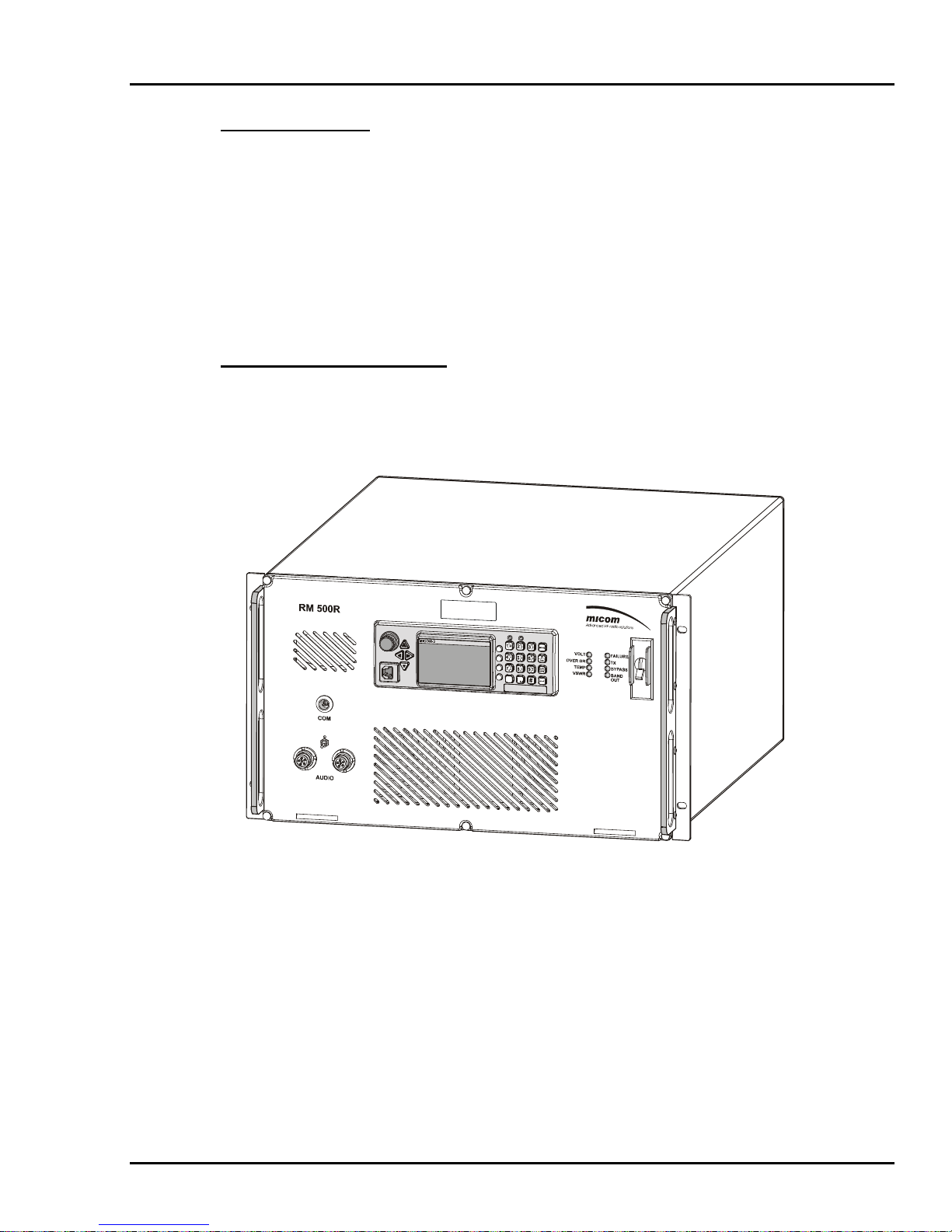
1.2 GENERAL DESCRIPTION
The MICOM RM500 and RM500R are 500W HF SSB continuous duty radio sets. Figure
1 shows a general view of a typical 500W transceiver (the RM500R).
F1
F2
F3
F4
0
*
Figure 1-1. RM500R, General View
RM500 and RM500R expand the MICOM 3 product line by offering higher transmit
power and thus longer reach, and improved communications under bad propagation
conditions and/or strong interference.
RM500 and RM500R can be equipped with the ISB option (option G191), described in
Publication 6888882V01, which enables MICOM-3 radio sets to simultaneously
communicate on both the upper sideband (USB) and the lower sideband (LSB) of the
selected channel (RF carrier frequency). Moreover, when transmitting data, the internal
MICOM-3 modem enables using the whole bandwidth of the two sidebands (more than 6
1-1

Unclassified
General Description
kHz) to transmit the data stream. Therefore, the maximum available data rate is doubled
(19200 bps instead of 9600 bps).
Digital encryption, supported when the vocoder option is installed, provides privacy for
sensitive applications. The encryption keys are loaded by means of the MKL Key Loader.
An RM500 or RM500R radio set consists of a standard MICOM 3 transceiver tightly
integrated with a 500W RF power amplifier and a 110/220 VAC, 50/60 Hz AC-powered
power supply, all contained within a compact chassis suitable for installation in 19 in.
racks and shelves.
The AC input voltage range (110 and 220 VAC) is automatically switched, allowing
operation in the United States of America as well as in other countries. Internal cooling
fans allow for continuous-duty data transmission and operation over a wide temperatures
range. The radio set features four accessories connectors located on the rear panel to
facilitate the connection of optional accessories.
For operation in multiple-transmitter or split sites, the RM500 and RM500R can be
ordered with an interface for the Pre-Selector/Post-Selector (PPS) (option G65).
NOTE
The G65 option does not include the Pre-Selector/PostSelector (PPS) unit, which must be separately ordered.
The RM500/RM500R are very well suited for base station applications, and also support
remote control, using option G422AA (refer to Publication 2072-09682-00 for details)
RM500 and RM500R can be directly connected to a wide range of broadband or tuned
antennas, including whip, dipole, traveling wave, delta, and semi-delta antennas. To obtain
maximum forward power, a low VSWR antenna system should be used; however, in case
of excessive VSWR, protection circuits prevent damage by reducing the transmit power to
safe values. Thus, the RM500 and RM500R will always attempt to transmit at the
maximum safe power, even in case of mismatch.
Special circuits protect the RM500 and RM500R against overheating and various types of
malfunctions. In case a critical problem is detected, the protection circuits are activated
and bypass the internal 500W power amplifier: in this case, the MICOM 3 transceiver is
directly connected to the antenna. This enables normal reception, as well as transmission,
albeit at the lower power levels (up to 125W) the MICOM 3 transceiver can provide.
Front panel indicators indicate the type of problem that has been detected, to help the
operator correct it.
Because the RM500 and RM500R are part of the MICOM 3 line, they have similar
capabilities, characteristics and operational procedures as MICOM 3, thereby enabling
personnel familiar with the operation of MICOM 3 equipment to start using the
RM500/RM500R with minimal training.
1-2
 Loading...