

Micom RM125, RM125R Owner's Manual

RM125/RM125R
125W HF-SSB Rack-Mount/Desktop
Continuous Duty Transceivers
Owner’s Guide
Table of Contents
Introduction................................................................................................................... 2
Description.................................................................................................................... 2
General..................................................................................................................... 2
Equipment Versions .................................................................................................. 3
Main Features ........................................................................................................... 3
Major Accessories ..................................................................................................... 4
Performance Specifications ............................................................................................ 5
Main Technical Characteristics .................................................................................. 5
Accessories Connectors ............................................................................................. 7
Ordering Options...................................................................................................... 8
Familiarization with Equipment...................................................................................... 9
Front Panels .............................................................................................................. 9
RM125/RM125R Rear Panels .................................................................................. 10
RM125/RM125R Installation ........................................................................................ 12
Installation Planning Guidelines............................................................................... 12
Preparations for Installation ..................................................................................... 14
Installation Procedure – Basic Radio........................................................................ 14
Installation Procedure – Radio with PPS Option ...................................................... 16
RM125/RM125R Operation......................................................................................... 18
General................................................................................................................... 18
Preparations for Operation...................................................................................... 18
Operating Instructions............................................................................................. 18
RM1200 1 kW Power Amplifier Option ....................................................................... 19
1 kW System Description ........................................................................................ 19
Functional Description ............................................................................................ 20
RM1200 Main Technical Characteristics.................................................................. 22
Familiarization with RM1200 Equipment................................................................. 24
RM1200 Equipment Installation .............................................................................. 30
Preparations for Installation ..................................................................................... 31
Installation Procedure ............................................................................................. 32
RM1200 Operation................................................................................................. 34
6888882V02 1
Introduction
This manual covers the installation and operation of the MICOM RM125 and RM125R 125W HF-SSB
rack-mount/desktop continuous duty transceivers, part of the MICOM-3 line of HF-SSB radio sets. It
also presents the FLN3175 MICOM RM1200 1 kW linear high-power RF amplifier unit, which uses the
RM125 or RM125R as exciter for a complete 1 kW transceiver.
The manual covers only procedures specific to the MICOM RM125/RM125R and RM1200; the other
procedures, which are common to the whole MICOM-3 product line, are described in the “Owner’s
Guide, MICOM-3E/3T/3R HF-SSB Transceivers”, Publication 6886867J01, and in other MICOM-3
Supplements that cover optional features applicable to your radio set.
Description
General
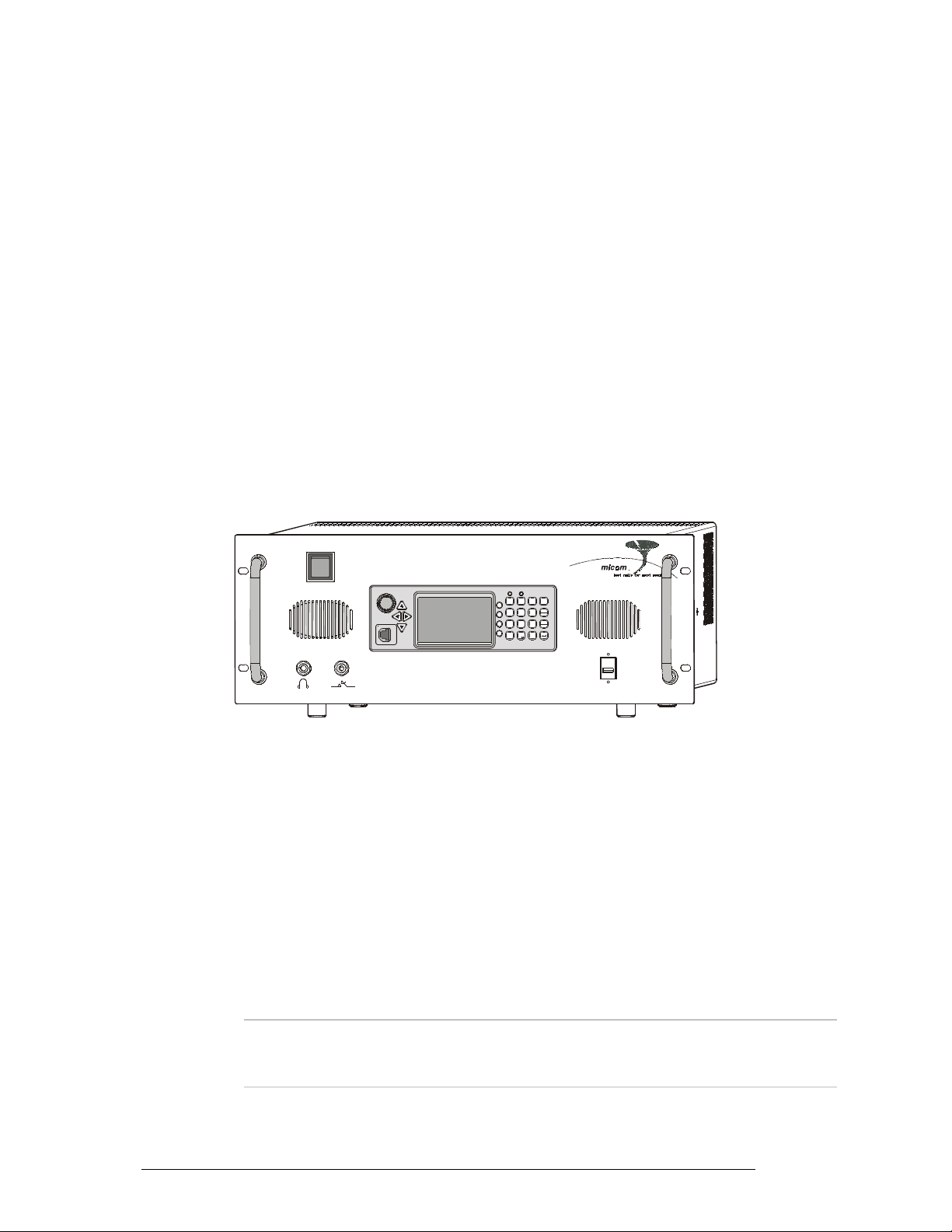
Figure 1 shows a general view of a typical 125W transceiver (the RM125 version).
MICOM RM-125
MICOM-3
A
D
?
BE
@
MENU
23
1
/
CF
F1
M
J
G
P
KN
H
56
4
Esc
L
I
O
F2
P
Y
T
ALARM
R
W
U
F3
Q
X
7
89
GPS
V
Z
S
F4
0
#
*
USB
Figure 1. Typical RM125, General View
The RM125/RM125R radio set includes a standard MICOM-3 transceiver, with a 110/220 VAC,
50/60 Hz power supply contained in a compact chassis, suitable for installation in a 19” rack or
desktop.
Internal cooling fans enable operation over a wide range of temperatures, for continuous-duty data
transmission. The radio has multiple accessories connectors, for system interconnections.
The AC input voltage range is automatically switched between 110 and 220 VAC, and therefore the
equipment can be used in the United States of America as well as in other countries. As a backup,
RM125/RM125R can also use 13.8 V DC power from an external lead-gel or lead-acid battery, which
is automatically charged by the internal AC power supply. When an external battery is connected, the
RM125/RM125R can continue operating on battery power during AC mains failure or in case the AC
power is switched off.
Note
An external 13.8 VDC DC power source, suitable for powering HF-SSB
transceivers, can also be used. The external source must be connected through a
series protection diode and a 30A fuse.
The RM125 and RM125R are well suited for base station applications, and can be directly connected
to a wide range of broadband or tuned antennas, including whip, dipole, traveling wave, delta, and
2 6888882V02
semi-delta antennas. Two main options further enhance the range of applications for the RM125 and
RM125R:
• MICOM RM1200 Linear High-Power RF Amplifier, FLN3175. This compact amplifier, which
covers the full transmit range of the RM125/RM125R, 1.60 to 30 MHz range, offers
significantly higher transmit power (1 kW PEP and average), and thus enable improved
communications under bad propagation conditions and/or strong interference.
• Interface for Pre-Selector/Post-Selector (PPS), option G65: the PPS is intended for RM125 and
RM125R installed in multiple-transmitter or split sites, as it permits operation of collocated
receivers and transmitters on frequencies separated by as little as 10%. The PPS operating
frequency range is 1.60 to 29.99 MHz.
Note
The G65 option does not include the Pre-Selector/Post-Selector (PPS) unit,
which must be separately ordered.
Being part of the MICOM-3 line, RM125 and RM125R offer similar capabilities and characteristics
and use common operating procedures, thereby enabling personnel familiar with the operation of
MICOM-3 equipment to start using the RM125/RM125R with minimal training.
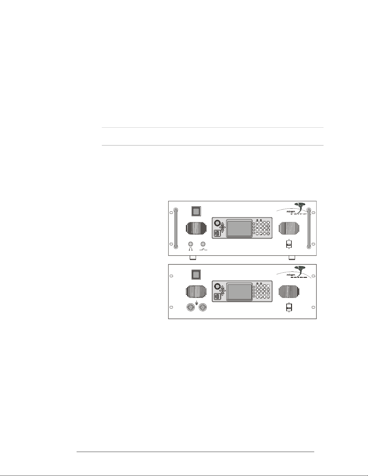
Equipment Versions
MICOM RM-125
MICOM RM125
Transceiver for long range wireless voice,
fax, data and email communications.
MICOM RM125R
Ruggedized transceiver with military
handset and connectors, for applications
requiring the utmost dependability and
reliability.
MICOM-3
MICOM RM-125R
MICOM-3
AUDIO
AD
?
@
MENU
BE
1
23
/
C
F
F1
JM
G
P
N
K
H
56
4
Esc
LO
I
F2
P
Y
T
ALARM
R
W
U
F3
89
Q
X
7
GPS
Z
V
S
F4
0
#
*
USB
AD
?
@
B
MENU
E
1
23
/
C
F
F1
M
J
G
P
N
K
H
56
4
Esc
LO
I
F2
P
Y
T
ALARM
R
W
U
F3
89
Q
X
7
GPS
S
Z
V
F4
0
#
*
USB
Main Features
• Automatic Link Establishment per FED-1045 & MIL-STD-188-141B standards (JITC certified)
• ISB (Independent Side Band) ready
• Full interoperability with other manufacturers' radios complying with the same ALE standards.
Voice that's loud & clear
• Built-in voice quality system utilizes proprietary algorithms to filter out background noises,
giving users exceptional communication clarity.
• Selectable bandwidth allows fine tuning for optimal voice and data communications.
• Voice-activated digital squelch.
6888882V02 3

User-friendliness
• New control head features a large LCD, full-dot matrix digital display and an enhanced
keyboard for programming and set-up.
• Radio operation can be executed using any standard USB keyboard.
• Multiple language display available.
• Transceiver can be controlled using PC and programming application.
• Remote control configuration, allows the transceiver to be operated from a remote location (at
a distance of up to 5 km) using the optional 2-wire remote control head.
Years of trouble-free, most advanced communications
• Upgrading to future technologies easily done by installing new software into the transceiver's
DSP unit.
• Easily replaceable digital components ensure cost-effective maintenance.
• Very high MTBF, as with all MICOM radios.
• Unique Built-In self Test (BIT) system provides exceptional dependability.
• Protection circuits enable transmission at maximum safe power
Comprehensive communication and networking services
• Office-quality communication services integrating fax, e-mail and data transmission and
reception.
• MultiNet option, enables integration of different HF radio networks into one seamless
network, allowing excellent coordination between different operational nets.
• AMD (Automatic Message Display) for free and pre-set text messages.
A proven family of radio products
• RM125 and RM125R are members of the MICOM transceiver family – fixed and mobile
stations – covering the long-range wireless communication needs of thousands of
organizations worldwide.
Major Accessories
• Antenna system and grounding kit
• 1 kW linear power amplifier
• Pre/Post-Selector (PPS)
• ATUs
• FM to HF repeater
• Automatic telephone interconnect
• HF modems
• Secure voice and data
• Vocoder
4 6888882V02

Performance Specifications
Main Technical Characteristics
This section presents the main technical characteristics of the RM125 and RM125R. For a listing of
the additional performance specifications, refer to the “Owner’s Guide, MICOM-3E/3T/3R HF-SSB
Transceivers”, Publication 6886867J01, and to the applicable MICOM-3 Supplements that cover the
optional features available on your radio set.
Models
General
RM125
RM125R
Number of channels
Transmission frequency range
Transmit power (PEP and average)
Reception frequency range
Sensitivity (SINAD)
Audio bandwidth
Data bandwidth
Frequency stability
Frequency resolution
Number of accessories connectors
M91AMN0KV5-K with G638
M95AMN0KV5-K with G638
200
1.6 to 30 MHz
User-selectable levels
• Max: 125W
• High: 100W
• Medium: 62.5W
• Low: 25W
100 kHz to 30 MHz
0.3 µV for 10 dB SINAD
350 to 2700 Hz
300 to 3300 Hz
0.6 ppm (0.1 ppm optional)
10 Hz
4 (see Table 1)
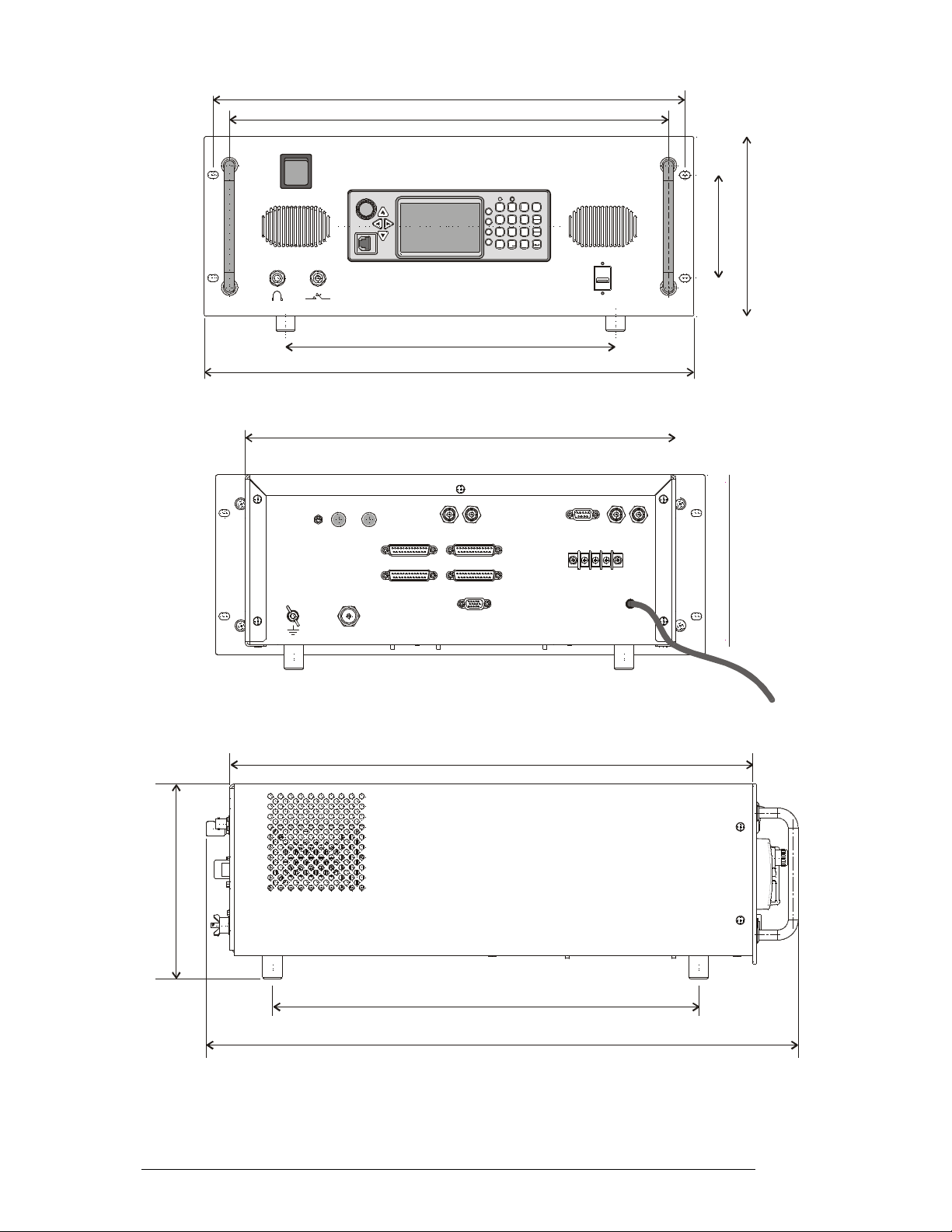
Dimensions
6888882V02 5
Operating voltage
Power requirements
External battery
Operating temperature range
Humidity
See Figure 2
• 110 /220 VAC, 50/60 Hz, with automatic
switching
• 13.8 VDC nominal from external battery
or DC power source
• Maximum 28 A from DC source
• Maximum 500W from AC source
(without charging)
Lead-gel or lead-acid, 13.8 VDC, max. 45Ah
C to +60°C/14°F to +140°F
°
-10
Up to 95% relative humidity @ 50
C/122°F
°
@
465
432.5
MICOM RM-125
MICOM-3
325
482.5
424
AD
?
BE
MENU
23
1
/
C
F
F1
M
J
G
P
KN
H
56
4
Esc
I
L
O
F2
T
P
Y
ALARM
R
W
U
F3
Q
X
89
7
GPS
Z
V
S
F4
0
#
*
177
101.6
USB
REMOTE CONTROL
ON
OFF
RF OUT
ACC-J1
ACC-J2
TX IN
RX IN
ACC-J4
ACC-J3
AMP-CONT
PPS-CONT TX OUT RX OUT
BAT
-
+
13.8V
AC
110/220V
169
AC Power
Cable
515
192
420
583.1
Figure 2. RM125/RM125R Dimensions
6 6888882V02

Accessories Connectors
The functions of the 25-pin accessories connectors, ACC-J1 to ACC-J4, are listed in Table 1. The
connectors include PTT and CW control lines, audio and baseband lines for external equipment,
auxiliary power output, serial RS-232 asynchronous data interfaces, and additional dedicated
handshaking and control lines. The functions supported by the serial data interfaces are determined
by the RM125/RM125R software.
Table 1. 25-Pin Accessories Connector, Pin Functions
Pin Designation Description
1 SPKR-
2 EXT RX DATA-
3 SPKR+
4 EXT RX AUDIO+
5 EXT RX AUDIO-
6 EXT TX AUDIO+
7 EXT TX AUDIO-
8 PTT IN VOICE Transmission command (short to ground) for voice signals
9 PTT IN DATA Transmission command (short to ground) for data signals
10 PTT IN CW Transmission command (short to ground) for CW (Morse) signals
11 SW A+ Primary DC voltage current limited output (max 1A)
12 DSI/KW C C BDM – Data serial in/kW amplifier channel change
13 KW ON/OFF kW amplifier power on/off output
14 EXT RX DATA+
15 RXA Receive input (point-to-point protocol to host/HLC)
16 TXA Transmit output (point-to-point protocol to host/HLC)
Differential output to the external 8Ω, 8W speaker
Baseband output (0 dBm, 600 Ω)
Differential output to the external 8Ω, 8W speaker
Differential received audio output (0 dBm, 600Ω; not controlled by volume, but
affected by squelch)
Differential transmit audio input (600Ω input impedance; 0 dBm is required for
full power)
Baseband output (0 dBm, 600 Ω)
17 EX RESET External RESET input (for BDM)
18 GND Ground
19 KW PTT PTT output to kW amplifier
20 EXT ALARM External alarm output (open collector, pulled to ground when external alarm is
activated
21 VPP Flash programming voltage, input to BDM
22 DSC/KW_ALC BDM – Data serial clock/kW amplifier ALC
23 SQ GATE Squelch open/closed indication output
24 DSO/FAN ON/OFF BDM – Data serial out/Fan control
25 FREEZE/KW TU BDM – Freeze/kW amplifier tune
6888882V02 7

Ordering Options
G424 (FVN4841) Add PC control and programming software package
S809 (FLN2515) Enhanced Interface cable kit for CW key & headphones
G112 Enhanced High frequency stability option (0.1 ppm)
G849 Add Interface option for external voice privacy device (VP-116)
G419 Enhanced USB COM port for connecting external keyboard
G423 Add ALE DTM/DBM (data transfer message/data block message)
S308 (FLN2517) Add Interface cable kit for phone patch
G561 (FLN2530) Add Interface cable for MICOM link unit
G65 Add Interface for Pre/Post-Selector (PPS) for co-site and split-site
applications
G420 Add 2-wire remote control head
G156 Add Interface cable kit for MICOM RM1200 1 kW linear amplifier
FLN3175 Add MICOM RM1200 1 kW (PEP and average) continuous duty linear
amplifier unit
8 6888882V02
Familiarization with Equipment
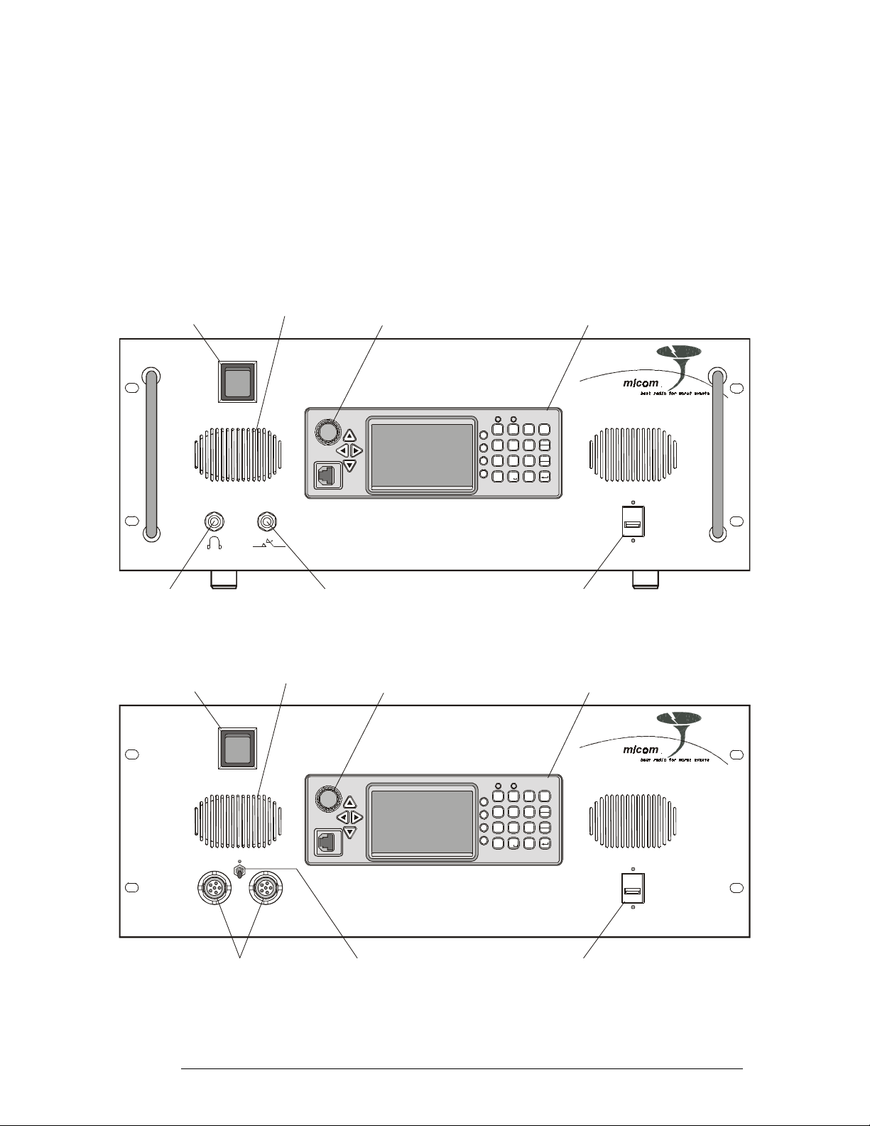
Front Panels
The front panels of the RM125 and RM125R include a standard MICOM-3 control panel and the
additional items identified in Figure 3, respectively Figure 4.
For a description of the MICOM-3 control panel, refer to the “Owner’s Guide, MICOM-3E/3T/3R
HF-SSB Transceivers”, Publication 6886867J01.
AC Power
ON/OFF Switch
Internal Speaker
ON/OFF & Volume Control
Turns transceiver on and off
and controls the speaker volume
MICOM RM-125
Standard MICOM-3
PanelControl
Headphone
Jack
AC Power
ON/OFF Switch
Telegraphy Key
Jack
Internal Speaker
MICOM- 3
A
?
@
BE
23
1
/
C
F1
JM
G
KN
H
56
4
LO
I
F2
P
T
R
U
F3
Q
7
89
V
S
F4
0
*
Connector for Optional
External USB Keyboard
Figure 3. RM125 Front Panel
ON/OFF & Volume Control
Turns transceiver on and off
and controls the speaker volume
MICOM RM-125R
MICOM-3
A
?
@
BE
23
1
/
CF
F1
J
G
KN
H
56
4
LO
I
F2
P
T
R
U
F3
Q
7
89
V
S
F4
0
*
D
MENU
F
P
Esc
Y
ALARM
W
X
GPS
Z
#
Standard MICOM-3
D
MENU
M
P
Esc
Y
ALARM
W
X
GPS
Z
#
USB
PanelControl
AUDIO
Audio Connectors for
External Speaker
and Handset
Internal Speaker
ON/OFF Switch
Connector for Optional
External USB Keyboard
USB
Figure 4. RM125R Front Panel
6888882V02 9
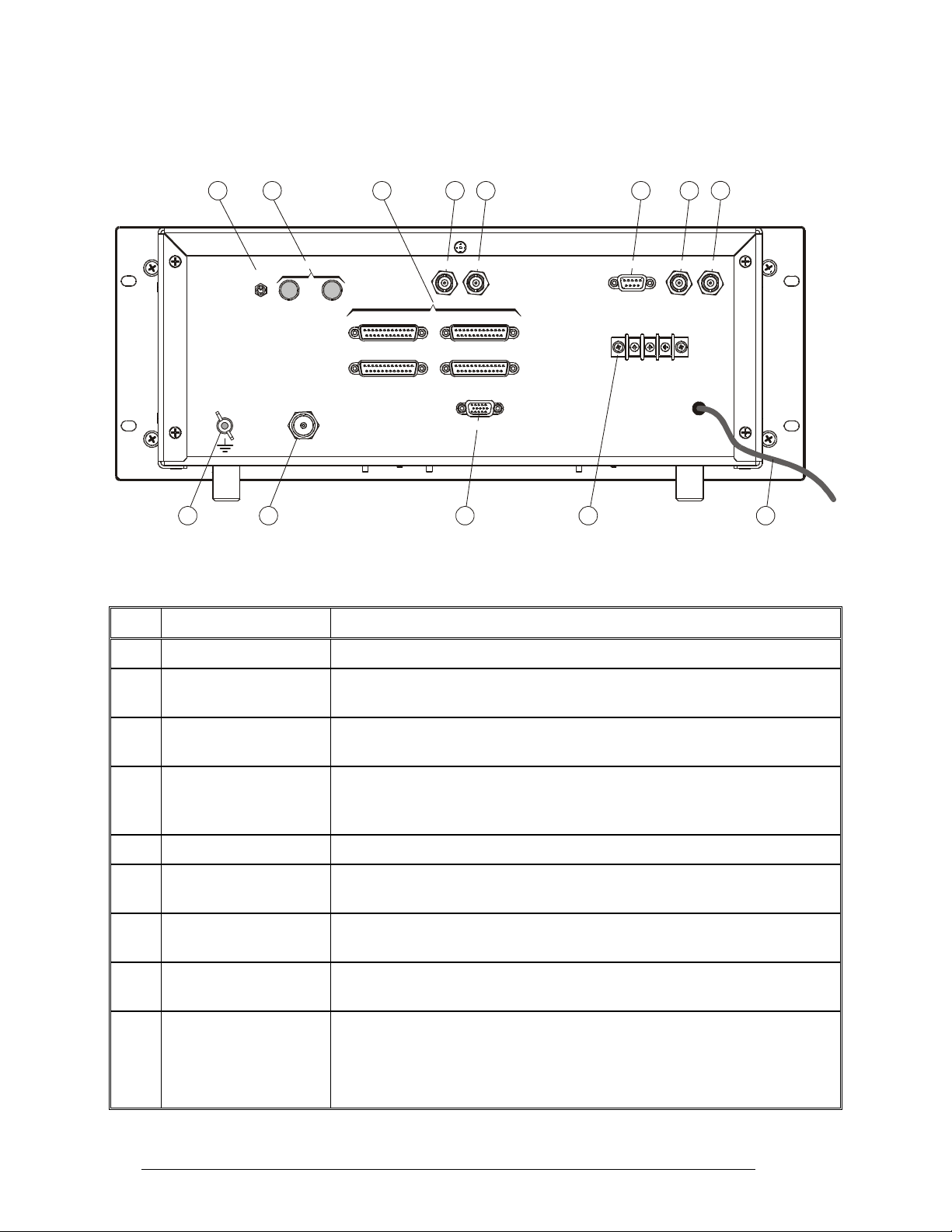
RM125/RM125R Rear Panels
Figure 5 shows the rear panel of the RM125 and RM125R. The functions of the various items are
explained in Table 2.
13 12 11 10
REMOTE CONTROL
ON
OFF
ACC-J1
ACC-J2
RF OUT
Figure 5. RM125/RM125R Rear Panel
Table 2. RM125/RM125R Rear Panel Items
Item Description Function
TX IN
9 6
RX IN
ACC-J4
ACC-J3
AMP-CONT
PPS-CONT TX OUT RX OUT
BAT
-
+
13.8V
78
AC
110 /22 0V
53214
1 Grounding Screw Connection of ground to the RM125/RM125R
2 RF OUT Connector UHF connector for connection of feed cable to antenna. Serves as the radio
set RF input in the receive mode, and as the RF output in the transmit mode
3 AMP-CONT Connector 15-pin D-type male connector, for connection of control signals to the 1 kW
power amplifier, RM1200
4 DC Connection Strip Connection to external 13.8 V rechargeable lead-gel or lead-acid battery, or
input for 13.8 VDC from external power source (via series protection diode
and fuse)
5 AC Power Cable Connection to 110/220 VAC power source
6 RX OUT Connector BNC RF output connector, for connection of unfiltered RF receive signal to
the optional Pre/Post-Selector (PPS)
7 TX OUT Connector BNC RF output connector, for connection of unfiltered RF transmit signal to
the optional Pre/Post-Selector (PPS)
9 PPS-CONT Connector 9-pin D-type female connector, for connection of control signals to the
optional Pre/Post-Selector (PPS)
11 ACC-J1 to ACC-J4
Connectors
Four 25-pin D-type male connectors, for connection to external options, for
example, voice privacy devices, modems, vocoders, etc.
Connector ACC-J2 is used for connection to the parallel I/O interface of the
optional Pre/Post-Selector (PPS)
10 6888882V02

Table 2. RM125/RM125R Rear Panel Items (Cont.)
Item Description Function
11 TX IN Connector BNC RF input connector, for connection of filtered RF transmit signal from
the optional Pre/Post-Selector (PPS)
12 REMOTE CONTROL
Connection of 2-wire line to optional 2-wire control head
Terminals
12 RX IN Connector BNC RF input connector, for connection of filtered RF receive signal from
the optional Pre/Post-Selector (PPS)
13 REMOTE CONTROL
Enables/disables remote control by the optional 2-wire control head
Switch
6888882V02 11
 Loading...