

Page 1

OM-E 2072-09287-00
INSTALLATION AND OPERATOR
MAINTENANCE MANUAL
FOR
Micom Pathfinder
5 - 25 Watt HF-SSB
Manpack Transceiver
Revision C
NOVEMBER 2010
Page 2

Page 3
OM-E 2072-09287-00
WARNINGS, CAUTIONS AND NOTES
The following notations are used to place special emphasis on procedures, or to call attention to
precautionary measures.
WARNING
An operating procedure, practice and so forth, which if not followed correctly,
could result in personal injury, or loss of life.
CAUTION
An operating procedure, practice and so forth, which if not followed correctly,
could result in damage to, or destruction of equipment.
NOTE
An operating procedure, condition and so forth, to which special attention
should be paid.
GENERAL SAFETY PRECAUTIONS
During transmission, high RF voltages may appear at the RF connectors, the
antenna cable, and on the antenna itself.
Avoid touching the antenna and the RF connectors of a radio set while it
operates.
Make sure the antenna is not located near high-voltage lines.
Operating and maintenance personnel must be familiar with the applicable
safety requirements before attempting to install or operate the radio set.
WARNING
Lithium-Ion batteries contain dangerous chemicals. Handle and dispose of
Lithium-Ion batteries according to the prescribed safety regulations. In
particular, observe the following precautions:
1. Do not short-circuit Lithium-Ion batteries.
2. Do not damage battery case and do not tamper with battery in any way.
3. Do not try to recharge the battery, except by means of the supplied
battery charger.
4. Do not expose to heat or flame.
5. Do not dispose of used Lithium-Ion batteries by burning.
CAUTION
Do not transmit with radio on your back. Place radio on ground before
starting transmit/receive communication, and connect it to the grounding
spike in accordance with Chapter 2.
i
Page 4

OM-E 2072-09287-00
FEDERAL COMMUNICATION COMMISSION REGULATIONS
The FCC has established limits for safe exposure to radio frequency (RF) emissions from mobile
two-way radios. The FCC requires manufacturers to demonstrate compliance with RF exposure limits
before mobile two-way radios can be marketed in the U.S. When two-way radios are approved for
occupational/controlled environment exposure limits, the FCC requires users to be fully aware of, and
exercise control over, their exposure. Awareness and control of RF exposure can be accomplished by
education or training through appropriate means such as information and instructions in user manuals
or safety booklets, or other appropriate means. This user safety booklet includes useful information
about RF exposure and helpful instructions on how to control your RF exposure.
Your two-way radio is designed and tested to comply with a number of national and international
standards and guidelines (listed below) regarding human exposure to radio frequency electromagnetic
energy. This radio complies with the IEEE (FCC) and ICNIRP exposure limits for
occupational/controlled RF exposure environments at usage factors of up to 10% talk-90% listen. In
terms of measuring RF energy for compliance with FCC exposure guidelines, your radio radiates
measurable RF energy only while it is transmitting (during talking), not when it is receiving (listening) or
in standby mode.
Your two-way radio complies with the following RF energy exposure standards and guidelines:
• United States Federal Communications Commission, Code of Federal Regulations; 47CFR part
2 sub-part J
• American National Standards Institute (ANSI)/Institute of Electrical and Electronic Engineers
(IEEE) C95.1-1992
• Institute of Electrical and Electronic Engineers (IEEE) C95.1-1999 Edition
• International Commission on Non-Ionizing Radiation Protection (ICNIRP) 1998
• Ministry of Health (Canada) Safety Code 6: Limits of Human Exposure to Radiofrequency
Electromagnetic Fields in the Frequency Range from 3 kHz to 300 GHz, 1999
• Australian Communications Authority Radiocommunications (Electromagnetic Radiation –
Human Exposure) Standard, 2001
• ANATEL, Brasil Regulatory Authority, Resolution 256 (April 11, 2001). Additional Requirements
for SMR, Cellular and PCS Product Certification.
SAFETY SUMMARY
The following are general safety precautions that are not related to any specific procedures and
therefore do not appear elsewhere in this publication. These are recommended precautions that
personnel must understand and apply during various phases of operation and maintenance.
KEEP AWAY FROM LIVE CIRCUITS. Operating personnel must at all times observe all safety
regulations. Do not replace components or make adjustments inside the equipment with the high
voltage supply turned on. Under certain conditions, dangerous potentials may exist even when the
power control is in the OFF position, due to charges retained by capacitors. To avoid casualties,
always remove power and discharge and ground a circuit before touching it.
DO NOT SERVICE OR ADJUST ALONE. Under no circumstances should any person reach into the
equipment enclosure for the purpose of servicing or adjusting the equipment except in the presence of
someone who is capable of rendering aid.
RESUSCITATION. Personnel working with or near high voltages should be familiar with modern
methods of resuscitation.
USE SAFETY APPROVED EQUIPMENT. When cleaners and primers are being applied, approved
explosion-proof lights, blowers, and other equipment shall be used. Insure that firefighting equipment is
readily available and in working order.
GIVE CLEANERS SPECIAL CARE. Keep cleaners in special polyethylene bottles or in safety cans
and in minimum quantities. Discard soiled cleaning cloths into safety cans.
ii
Page 5

OM-E 2072-09287-00
TABLE OF CONTENTS
CHAPTER 1 GENERAL DESCRIPTION
1-1. SCOPE .......................................................................................................................... 1-1
1-2. PURPOSE AND USE .................................................................................................... 1-1
1-3. EQUIPMENT DESCRIPTION........................................................................................ 1-2
1-3.1 Micom Receiver/Transmitter.................................................................................... 1-2
1-3.2 Carrying Harness .................................................................................................... 1-3
1-3.3 FAD5530 Collapsible 9-Foot Whip Antenna ........................................................... 1-3
1-3.4 FAA5548 Portable Dipole Antenna ......................................................................... 1-4
1-3.5 GPS Antenna, AT-1000 (for Use with Option G421) ............................................... 1-4
1-3.6 Handset, FMN5501 ................................................................................................. 1-4
1-3.7 Loudspeaker, LS-108M (Optional) .......................................................................... 1-4
1-3.8 16 Ah Lithium-Ion Battery, FRN8577....................................................................... 1-5
1-3.9 Utilities..................................................................................................................... 1-5
1-4. TECHNICAL CHARACTERISTICS ............................................................................... 1-6
CHAPTER 2 INSTALLATION
2-1. SCOPE .......................................................................................................................... 2-1
2-2. UNPACKING ................................................................................................................. 2-1
2-3. MICOM PATHFINDER ASSEMBLY PROCEDURE...................................................... 2-2
2-3.1 Installation of Battery ............................................................................................... 2-2
2-3.2 Installation in Carrying Harness .............................................................................. 2-3
2-3.3 Installation of Whip Antenna ................................................................................... 2-7
2-3.4 Connection of Audio Accessories............................................................................ 2-8
2-3.5 Wearing Backpack Carrying Harness ..................................................................... 2-8
2-3.6 Operating Micom Pathfinder on Ground.................................................................. 2-8
2-4. USING THE FAA5548 TACTICAL DIPOLE ANTENNA ................................................ 2-8
CHAPTER 3 OPERATING PROCEDURES
3-1. SCOPE .......................................................................................................................... 3-1
3-2. MICOM CONTROLS, INDICATORS AND CONNECTORS ......................................... 3-1
3-3. FAMILIARIZATION WITH MICOM OPERATING PROCEDURES ............................... 3-3
3-3.1 Display Functions .................................................................................................... 3-3
3-3.2 Audible Indications .................................................................................................. 3-7
3-4. MENU STRUCTURE..................................................................................................... 3-8
3-4.1 Displaying the Main Menu ....................................................................................... 3-8
3-4.2 What you can Select on the Main Menu.................................................................. 3-9
3-4.3 Notational Conventions ........................................................................................... 3-9
3-5. GETTING STARTED................................................................................................... 3-10
3-5.1 Turning the Radio On and Off ............................................................................... 3-10
3-5.2 Preparation for Operation ...................................................................................... 3-11
3-5.3 Transmitting and Receiving ................................................................................... 3-13
3-6. USING THE CHANNEL MODE ................................................................................... 3-14
3-6.1 Channel Mode Options.......................................................................................... 3-14
3-6.2 Selecting the Channel Mode ................................................................................. 3-15
3-6.3 Choosing a Different Channel ............................................................................... 3-16
3-7. USING THE FREQUENCY MODE.............................................................................. 3-17
3-7.1 Frequency Mode Options ...................................................................................... 3-17
3-7.2 Selecting the Operating Frequency in the FREQ Mode ........................................ 3-19
3-7.3 Storing Frequencies .............................................................................................. 3-22
3-8. USING THE SCAN MODE .......................................................................................... 3-23
3-8.1 Selecting the Scan Mode ...................................................................................... 3-23
3-8.2 Scan Mode Options ............................................................................................... 3-23
3-9. USING THE GPS RECEIVER (OPTIONAL) ............................................................... 3-24
3-9.1 Overview of GPS Receiver Functions ................................................................... 3-24
3-9.2 How to Get the Best Results from your Micom GPS Receiver .............................. 3-24
3-9.3 Operating the GPS Receiver ................................................................................. 3-24
3-10. LOCKING/UNLOCKING THE RADIO ......................................................................... 3-27
3-11. CHANGING THE PASSWORD ................................................................................... 3-28
Page
iii
Page 6

OM-E 2072-09287-00
TABLE OF CONTENTS (Cont'd)
3-12. USING AUTOMATIC LINK ESTABLISHMENT (ALE)................................................. 3-29
3-12.1 Enabling the ALE Mode......................................................................................... 3-29
3-12.2 ALE Mode Options ................................................................................................ 3-30
3-12.3 Receiving and Transmitting Calls in ALE Mode .................................................... 3-31
3-12.4 Using ALE Mode to Send and Request GPS Position Data.................................. 3-57
3-13. USING THE VOCODER.............................................................................................. 3-58
3-13.1 Introduction............................................................................................................ 3-58
3-13.2 Using the Vocoder ................................................................................................. 3-58
3-13.3 Programming the Vocoder .................................................................................... 3-59
3-14. OPERATION UNDER UNUSUAL CONDITIONS........................................................ 3-62
3-14.1 Operation in Desert Areas ..................................................................................... 3-62
3-14.2 Operation at Low Temperatures ............................................................................ 3-62
3-14.3 Operation During Storms....................................................................................... 3-62
CHAPTER 4 USING THE PROGRAMMING MODE
4-1. SCOPE .......................................................................................................................... 4-1
4-2. THE PROG MENU ........................................................................................................ 4-1
4-3. PROGRAMMING THE RADIO PARAMETERS ............................................................ 4-2
4-3.1 Programming Channels........................................................................................... 4-3
4-3.2 Configuring Radio Parameters ................................................................................ 4-5
4-3.3 Setting Radio Options ............................................................................................. 4-6
4-4. ALE PROGRAMMING................................................................................................... 4-7
4-4.1 Programming Nets .................................................................................................. 4-9
4-4.2 Setting the Net Options ......................................................................................... 4-11
4-4.3 Directory Parameters ............................................................................................ 4-11
4-4.4 AMD Message Configuration................................................................................. 4-11
4-4.5 ALE Options Configuration .................................................................................... 4-12
4-4.6 Auto Dial Parameters ............................................................................................ 4-13
4-4.7 Storing ALE parameters ........................................................................................ 4-14
4-4.8 Using the New Station Address Filter.................................................................... 4-14
CHAPTER 5 OPERATOR MAINTENANCE
5-1. GENERAL ..................................................................................................................... 5-1
5-2. VISUAL INSPECTION AND MECHANICAL CHECKS.................................................. 5-1
5-2.1 Inspection ................................................................................................................ 5-1
5-2.2 Cleaning .................................................................................................................. 5-2
5-3. CORRECTIVE MAINTENANCE.................................................................................... 5-3
APPENDIX A USING BATTERY CHARGER, FRN8570B
A-1. PURPOSE AND USE ....................................................................................................A-1
A-2. FRN8570B DESCRIPTION ...........................................................................................A-1
A-3. FUNCTIONAL DESCRIPTION ......................................................................................A-1
A-4. FRN8570B OPERATING INSTRUCTIONS ..................................................................A-2
A-4.1 Familiarization with Charger Unit............................................................................. A-2
A-4.2 Preparations for Charging ....................................................................................... A-3
A-4.3 Charging Process.................................................................................................... A-3
A-5. MAIN FRN8570B TECHNICAL SPECIFICATIONS ......................................................A-4
APPENDIX B INSTALLATION OF FAA5548 TACTICAL DIPOLE ANTENNA
B-1. SCOPE ..........................................................................................................................B-1
B-2. FAA5548 DESCRIPTION ..............................................................................................B-1
B-3. ANTENNA CONFIGURATIONS....................................................................................B-1
B-3.1 Horizontal Dipole ..................................................................................................... B-2
B-3.2 Inverted V Dipole..................................................................................................... B-2
B-3.3 Sloping Dipole ......................................................................................................... B-3
B-3.4 Wire Antenna Configuration .................................................................................... B-4
B-4. FAA5548 INSTALLATION PROCEDURE.....................................................................B-4
APPENDIX C ALE CAPABILITIES AND FEATURES
C-1. SCOPE..........................................................................................................................C-1
C-2. SCANNING....................................................................................................................C-1
Page
iv
Page 7

OM-E 2072-09287-00
TABLE OF CONTENTS (Cont'd)
C-3. SOUNDING ...................................................................................................................C-1
C-3.1 Sounding Cycle Time .............................................................................................. C-1
C-3.2 Manual Sounding .................................................................................................... C-2
C-4. LQA MEMORY ..............................................................................................................C-3
C-5. BIDIRECTIONAL HANDSHAKE....................................................................................C-3
C-6. SELECTIVE CALLING ..................................................................................................C-4
C-6.1 ALE Addressing Method.......................................................................................... C-4
C-6.2 Address and Call Types .......................................................................................... C-4
C-7. USING THE MULTINET FEATURE ..............................................................................C-8
C-8. MESSAGES...................................................................................................................C-8
C-9. USING THE CALLER STACK.......................................................................................C-8
C-10. QUICK CALL .................................................................................................................C-9
Page
v
Page 8

OM-E 2072-09287-00
LIST OF ILLUSTRATIONS
Page
Figure 1-1. Micom Pathfinder, General View ................................................................................................. 1-1
Figure 1-2. Micom Receiver/Transmitter........................................................................................................ 1-2
Figure 1-3. Micom Pathfinder Carrying Harness, General View (Closed for Transport) ............................1-3
Figure 1-4. GPS Antenna, AT-1000 ...............................................................................................................1-4
Figure 1-5. GPS Antenna Adapter, AD-1000P ..............................................................................................1-4
Figure 1-6. Rechargeable Lithium-Ion Battery, FRN8577............................................................................. 1-5
Figure 1-7. PC-Micom Data Cable ................................................................................................................. 1-5
Figure 2-1. Installing the Battery ..................................................................................................................... 2-2
Figure 2-2. Carrying Harness, Front View (Closed)....................................................................................... 2-3
Figure 2-3. Carrying Harness with Front Flaps Raised ................................................................................. 2-4
Figure 2-4. Installing Transceiver in Carrying Harness.................................................................................. 2-5
Figure 2-5. Detail of Transceiver in its Carrying Harness............................................................................. 2-6
Figure 2-6. GPS Antenna Installed on Harness.............................................................................................2-6
Figure 3-1. Micom Front Panel Controls, Indicators and Connectors........................................................... 3-1
Figure 3-2. MICOM Rear Side Connectors....................................................................................................3-2
Figure 3-3. Main Menu .................................................................................................................................... 3-9
Figure 3-4. Channel (CHAN) Menu..............................................................................................................3-14
Figure 3-5. FREQ (Frequency) Menu...........................................................................................................3-17
Figure 3-6. GPS Menu ..................................................................................................................................3-25
Figure 3-7. ALE Operator Menu ...................................................................................................................3-30
Figure 3-8. VCD Programming Menu........................................................................................................... 3-60
Figure 4-1. PROG Menu – Radio Parameters Programming.......................................................................4-2
Figure 4-2. PROG Menu – ALE Parameters Programming ......................................................................... 4-7
Figure A-1. Charger Unit, General View.........................................................................................................A-2
Figure B-1. Horizontal Dipole Configuration ...................................................................................................B-2
Figure B-2. Inverted V Configuration...............................................................................................................B-3
Figure B-3. Sloping Dipole Configuration........................................................................................................B-3
Figure C-1. Network Occupancy .....................................................................................................................C-2
vi
Page 9

OM-E 2072-09287-00
LIST OF TABLES
Page
Table 1-1. DATA Connector, Pin Functions.................................................................................................. 1-8
Table 1-2. AUDIO Connectors, Pin Functions..............................................................................................1-8
Table 5-1. Visual Inspection and Mechanical Checks.................................................................................. 5-1
Table 5-2. Fault Messages............................................................................................................................ 5-4
Table A-1. Status Indications .........................................................................................................................A-2
Table C-1. Use of “@” Stuffing Symbol..........................................................................................................C-5
Table C-2. Use of “?” Wildcard Symbol.........................................................................................................C-6
vii
Page 10

OM-E 2072-09287-00
Intentionally Left Blank
viii
Page 11
OM-E 2072-09287-00
CHAPTER 1
GENERAL DESCRIPTION
1-1. SCOPE
This manual provides instructions regarding the installation and operator maintenance of the Micom
Pathfinder, a portable high-frequency (HF) single sideband (SSB) manpack radio set. The manual is
organized as follows:
Chapter 1 General Description: provides a general description of the Micom Pathfinder and its
main components, and presents the main technical characteristics.
Chapter 2 Installation: provides installation instructions for Micom Pathfinder.
Chapter 3 Operating Instructions: describes the equipment and the functions of the various
controls and indicators, and presents operating instructions.
Chapter 4 Using the Programming Mode: provides detailed instructions for programming the
Micom Pathfinder parameters needed in the various operating modes.
Chapter 5 Operator Maintenance: provides operator maintenance instructions.
Appendix A Using Battery Charger, FRN8570B: provides instructions for using the FRN8570B to
charge Micom Pathfinder battery, FRN8577.
Appendix B Installation of FAA5548 Tactical Dipole Antenna: provides concise installation
instructions for the FAA5548 tactical dipole antenna.
Appendix C ALE Capabilities and Features: provides a concise description of the ALE
capabilities and features supported by Micom Pathfinder.
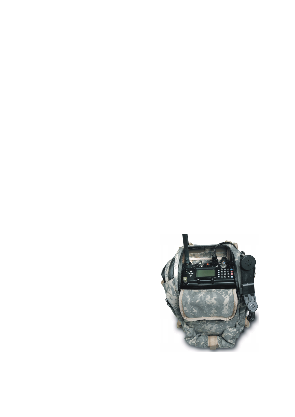
1-2. PURPOSE AND USE
Micom Pathfinder, a manpack version of the robust
Micom-3 mobile radio, is an advanced HF-SSB
transceiver that provides a complete solution to the
communication requirements in the crowded HF band.
It is part of the Micom-3 family of HF/SSB radio sets,
has compatible characteristics, and uses the same
operating procedures as other Micom-3 radio sets.
Micom Pathfinder has selectable transmit RF power of
5, 10, 15 and 25 W, and high sensitivity. Its built-in
automatic antenna tuner supports a wide range of
antennas, including a 2.7 meter (9 ft) whip which can
be easily folded for storage. For static operation,
Micom Pathfinder can also be used with dipole, long
wire and other types of broadband antennas.
Micom Pathfinder can be ordered with an optional
internal GPS receiver that provides accurate time and
navigation data.
Micom Pathfinder is powered by a rechargeable
Lithium-Ion battery, and is carried in a convenient,
lightweight harness that completely envelops the
transceiver, and enables carrying all the necessary
accessories.
Figure 1-1. Micom Pathfinder, General
View
1-1
Page 12
OM-E 2072-09287-00
The Micom Pathfinder capabilities provide reliable long-range HF-SSB radio communications in a
rugged yet lightweight manpack configuration. Designed to meet the needs of users who carry out
on-foot operations in remote areas, it is built to withstand years of shock and vibration as well as
severe weather conditions. Micom Pathfinder is certified for dependability and durability, and
complies with the applicable sections of MIL-STD-810F and MIL-STD-810E.
Micom Pathfinder supports voice and data communications. Micom Pathfinder supports data rates up
to 4800 bps by means of an optional internal (embedded) modem.
Extensive use of digital signal processing (DSP) ensures high performance; a built-in voice quality
system with proprietary DSP algorithms filter out background noise and elevates sound bytes
providing exceptional communication clarity and voice quality. Many advanced features are standard,
such as digital noise blanking and voice-activated digital squelch. Optional features such as embedded
data modem, embedded vocoder, embedded AES encryption, etc., are also available. Moreover, the
addition of new features and upgrading to future technologies are easily made by software updating.
To ensure the best possible communication reliability, Micom Pathfinder Automatic Link
Establishment (ALE) has been certified by the Joint Interoperability Test Center (JITC) to MIL-STD188-141B. In addition, the ALE function also provides Automatic Message Display (AMD), that
enables operators to exchange preprogrammed messages while establishing a link. The AMD function
is also used in several advanced optional features, such as automatic position reporting (either
operator-initiated or in response to queries) when a GPS receiver is installed, and automatic adoption
of the encryption key used by the transmitting station (provided the necessary key is available at the
receiving station).
1-3. EQUIPMENT DESCRIPTION
This section describes the main equipment units of the Micom Pathfinder radio set.
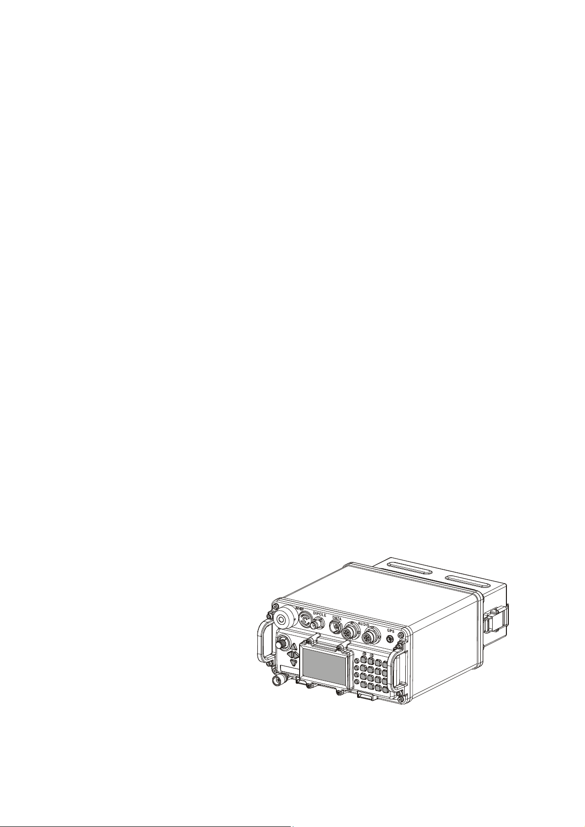
1-3.1 Micom Receiver/Transmitter
The Micom receiver/transmitter unit performs the following main functions:
• Generates the transmit signals.
• Demodulates the received signals.
• Processes the GPS signals (optional).
• Provides the interfaces to the operator, and to data equipment using Micom Pathfinder for radio
communications.
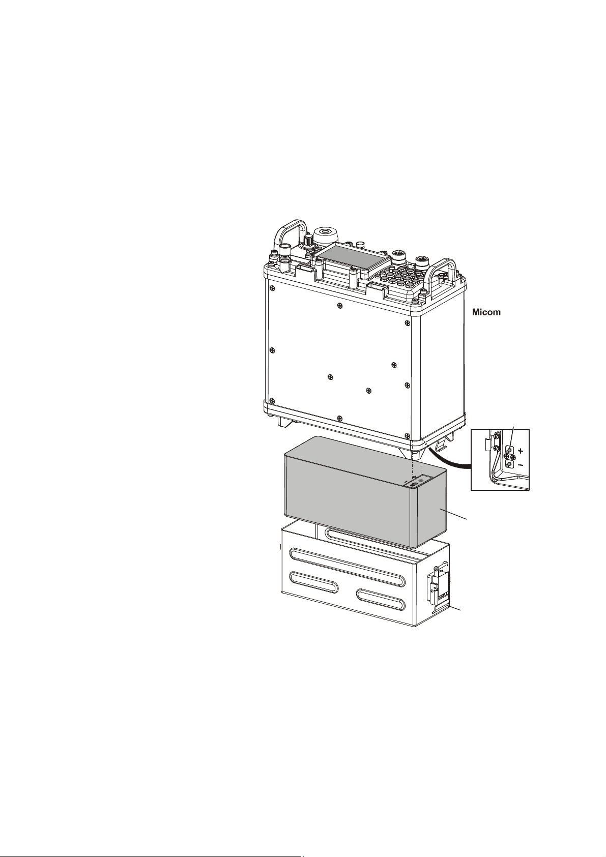
Figure 1-2 shows a general view of Micom, including its battery box.
Figure 1-2. Micom
Receiver/Transmitter
The Micom is a complete HF/SSB receiver-transmitter, powered by a 14.4 V Lithium-Ion battery
installed in a battery box attached to the rear side of the Micom by two clamps. The box houses the
battery and protects the battery against environmental elements.
1-2
Page 13
OM-E 2072-09287-00
The nominal output impedance of the Micom is 50 Ω, and therefore it can be directly connected to
broadband antennas (dipoles, traveling wave antennas, delta and semi-delta antennas). An internal
antenna tuner enables using various whip antennas (in addition to the 2.7 meter (9 ft) antenna offered
as a standard for the Micom Pathfinder). The transmitter includes antenna mismatch protection: if the
VSWR (Voltage Standing Wave Ratio) is too high, for example, because the antenna is disconnected
or damaged, the transmission will be inhibited to avoid damage, and a message will be displayed. In
addition, if for any reason, the transmitter internal temperature exceeds the maximum permitted
temperature, the transmitter output power is automatically reduced to avoid fault due to excessive heat.
The Micom has an intelligent, user-friendly man-machine interface that enables easy operation. The
display provides feedback to the operator and shows extensive information concerning system status
(e.g., mode of operation, link status, call progress indications, low battery condition, etc.), as well as
the GPS data (when this option is used). Support for multiple languages is also available.
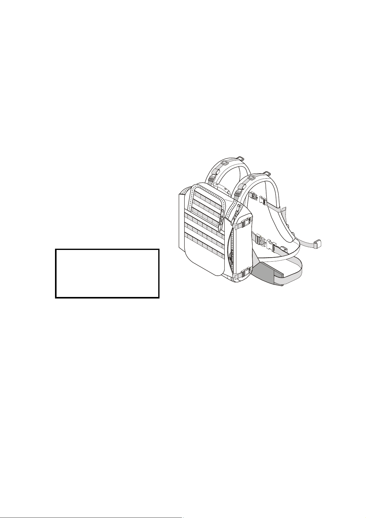
1-3.2 Carrying Harness
Micom Pathfinder carrying harness consists of
a lightweight nylon harness with adjustable
shoulder straps that enable carrying all the
necessary accessories. Additional waist and
breast straps, also easily adjustable for best fit
and user’s comfort, stabilize the harness while
walking and running.
A foldable rear support enables placing the
harness on ground, vertically, for dismounted
operation.
CAUTION
During dismounted operation, use
the supplied grounding spike and
strap to ground the Micom
Pathfinder unit.
Figure 1-3. Micom Pathfinder Carrying Harness,
General View (Closed for Transport)
For best equipment protection, the carrying harness completely envelops the transceiver. A front flap
with zippers provides easy access to the internal storage compartments for cables and spare battery,
and also permits the installation of the Micom transceiver. After installing the transceiver, the front
flap remains closed: a separate top flap can be opened to access the Micom front panel, install the
antenna and the handset, and operate the radio set.
Side pouches can be used to carry the folded whip antenna, and other accessories. The optional GPS
antenna is attached to the side of the harness.
1-3.3 FAD5530 Collapsible 9-Foot Whip Antenna
The FAD5530 whip antenna is the standard Micom Pathfinder antenna used for short-range
ground-wave communication, and is suitable for portable operation. Antenna matching is performed
by the Micom internal automatic antenna tuner, and thus FAD5530 is directly connected to the WHIP
connector of the Micom.
The FAD5530 whip antenna consists of two components:
• AT-271A Collapsible Antenna. The antenna is composed of six sections. Each section fits into
the end of a wider section. A stainless-steel plastic-covered cable (or braided plastic cord),
under spring tension, is threaded through the sections to keep them together when operating.
When the sections are folded, the cable keeps them together as a group, to prevent the loss of
individual sections. Spring tension is provided by a spiral spring in the base section.
1-3
Page 14
OM-E 2072-09287-00
• AB-591 Antenna Base Adapter. The antenna base adapter serves as the main support for the
AT-271A.
A safety strap is supplied to fasten the antenna sections together, when the radio set is transported with
the antenna folded.
1-3.4 FAA5548 Portable Dipole Antenna
The optional FAA5548 dipole antenna is a lightweight portable antenna for the frequency range of 2 to
30 MHz. This antenna is recommended for use during static operation, when long communication
ranges are required: when using a properly selected operating frequency, FAA5548 provides
continuous coverage for communication ranges of up to 1,000 kilometers.
The FAA5548 antenna consists of two antenna wires, which are attached to an insulator (center unit).
The insulator is connected by means of the coaxial feed cable to the front-panel DIPOLE connector.
The length of the antenna wires is coarsely adjusted in accordance with the operating frequency. Two
cords are used to stretch the wires. The cords are fastened to nearby supports, e.g. trees, poles, etc.
When properly adjusted to the operating frequency range, the FAA5548 input impedance is close to
50 Ω, and therefore it is possible to connect FAA5548 directly to the DIPOLE connector of the
Micom. When the selected operation mode involves automatic changing of the operating frequency,
e.g., for ALE operation, the antenna should be adjusted to the average operation frequency.
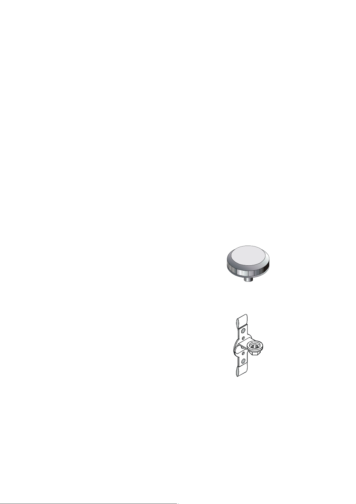
1-3.5 GPS Antenna, AT-1000 (for Use with Option G421)
The GPS antenna, AT-1000, is a compact active omnidirectional antenna which connects to the GPS
connector of the Micom through a coaxial cable that carries both DC power and the received GPS
signals. The AT-1000 has a threaded stud on its base, which can be used to fasten the antenna to an
appropriate adapter. Figure 1-4 shows a general view of the antenna.
Figure 1-4. GPS Antenna, AT-1000
For use in Micom Pathfinder, the required adapter is AD-1000P, and the coaxial cable is CG-5602.
AD-1000P is used to attach the AT-1000 to the Micom Pathfinder carrying harness. Figure 1-5 shows
a general view of the antenna adapter.
Figure 1-5. GPS Antenna Adapter, AD-1000P
1-3.6 Handset, FMN5501
FMN5501 is a dynamic handset with a noise-suppression microphone complying with MIL-H-49078
(EL). It has a five-pin audio connector for connection to one of the Micom AUDIO connectors.
1-3.7 Loudspeaker, LS-108M (Optional)
The LS-108M is a portable 0.3 W loudspeaker that connects to one of the AUDIO connectors on the
front panel of the Micom. The LS-108M is designed for field combat use, and may be attached to a
belt or harness. It allows a commander to monitor radio communications while the radio operator
remains in full control of the radio set.
1-4
Page 15
OM-E 2072-09287-00
Charge
Connector
Connector
PC-COM1
PC-COM2
A volume control on the housing provides adjustable sound level. The loudspeaker has an additional
AUDIO connector, which permits the connection of an additional handset.
1-3.8 16 Ah Lithium-Ion Battery, FRN8577
FRN8577 is a rechargeable Lithium-Ion battery that
provides a 14.4 V nominal voltage, and a nominal
Radio
capacity of 16 ampere-hours. The battery has a
plastic outer case with safety vent. The battery has
two connectors, one for powering the transceiver,
and the other for charging. Internal electronic
circuits protect against short-circuits, undervoltage,
excessive temperature, and overcharging.
1-3.8.1 Battery Charger, FRN8570B
Figure 1-6. Rechargeable Lithium-Ion Battery,
FRN8577
FRN8570B is a portable automatic battery charger for FRN8577 rechargeable Lithium-Ion batteries.
FRN8570B can be powered from 100 to 240 VAC, 50/60 Hz. Its operation is fully automatic, and thus
ensures full charging of batteries to their rated capacity, while prolonging the operational life of
batteries by providing optimum charging conditions.
Refer to Appendix A for additional information.
1-3.9 Utilities
To fully and efficiently utilize the Micom Pathfinder’s advanced capabilities, the following utility
packages are offered as options:
• The radio operational parameters can be programmed using the Micom Radio Control
Application (MRC), option FVN4841 (G424). For further details, refer to “Micom Radio
Control Application Owner’s Guide”, Publication OM-E 2072-09602-10.
• Data communications are supported by the MicomNET e-Mail/Gateway over HF Software
Package, covered by the “MicomNET e-Mail/Gateway over HF Software Package User’s
Guide”, Publication 6886864J01.
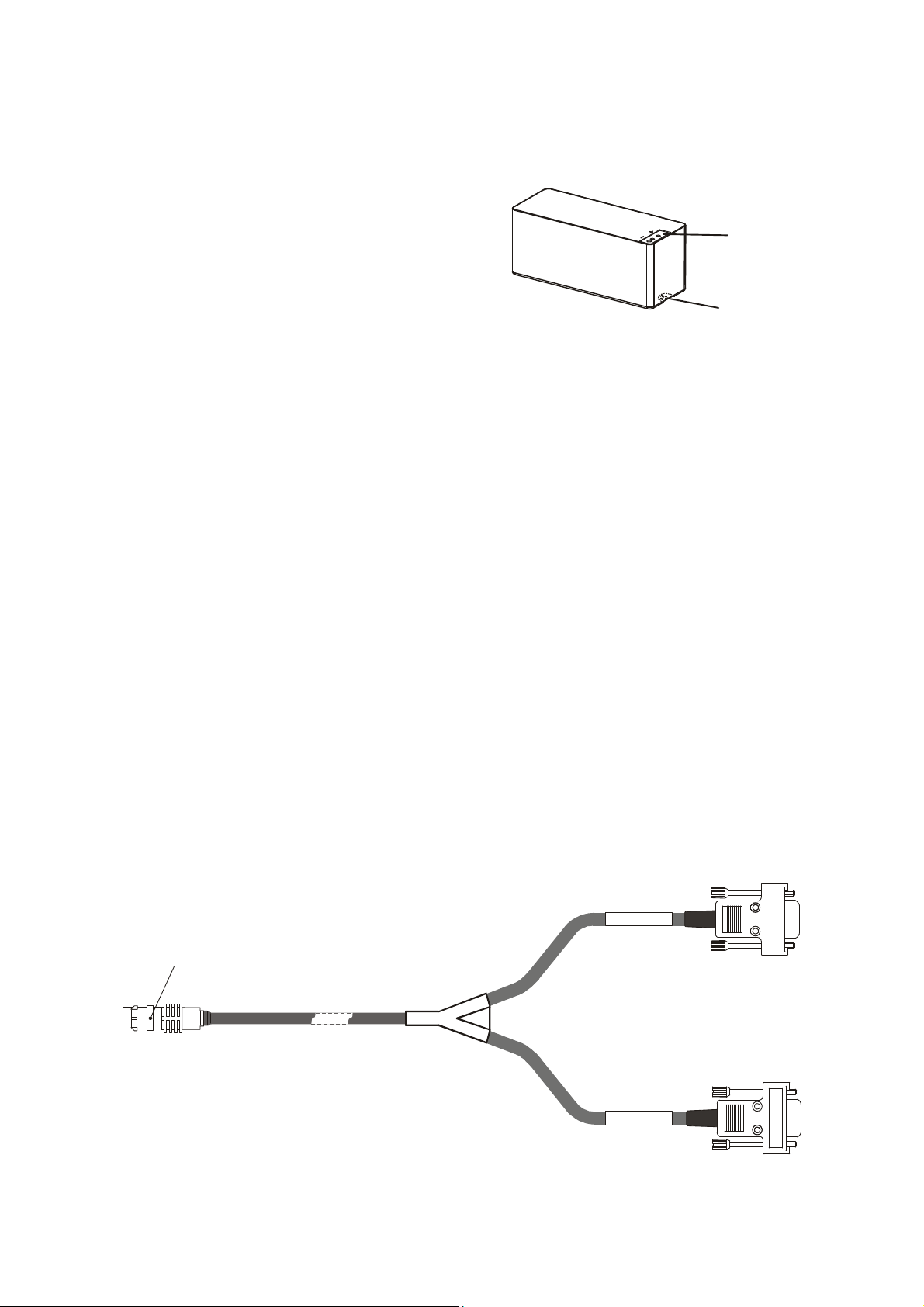
All the utilities listed above run on PCs using the Windows(™) operating system, and require two of
the serial RS-232 asynchronous (COM) ports of the PC for communication with the Micom
receiver/transmitter: COM2 is used as the radio control port, and COM1 is used as the modem data
port. A special data cable is available for connecting the two PC serial ports to the Micom DATA
connector.
Orientation
Dot
Figure 1-7. PC-Micom Data Cable
1-5
Page 16

OM-E 2072-09287-00
1-4. TECHNICAL CHARACTERISTICS
General
Model M95AMN0KV5-K+G873
Transmit Frequency Range 1.6 to 30 MHz
Receive Frequency Range 0.1 to 30 MHz (0.1 to 1.6 MHz reduced performance)
RF Impedance
• DIPOLE connector: 50 Ω
• WHIP connector: internal automatic tuner for whip antenna
Number of Channels 200 simplex or half duplex, user programmable
Scanning
• 5 groups with up to 100 channels per group, including 1 guard
channel.
• Programmable scan rate: 1 to 5 sec. per channel, in 1 sec. steps
ALE MIL-STD-188-141B, JITC certified, MultiNet support
Frequency Stability 0.6 ppm (0.1 ppm optional)
Frequency Resolution 10 Hz
Data and Remote Control
RS-232C
Interfaces
Modes of Operation
• SSB (USB or LSB, user-selectable)
• PILOT
• AME
Services
• Analog voice
• Digital voice (internal low-rate vocoder)
• Data using internal modem (50 to 4800 bps)
• COMSEC (digital NIST-certified advanced encryption system
(AES), available as option for the vocoder and/or internal
modem, internal storage of up to 7 keys)
Audio Bandwidth Automatic switching between voice and data
Voice Bandwidth 350 to 2700 Hz
Data Bandwidth Operator-selectable:
2.1 kHz: 350 to 2100 Hz
3.0 kHz: 350 to 3000 Hz
3.3 kHz: 350 to 3300 Hz (also used by internal modem)
Operating Voltage
Dimensions
13. 8 VDC ±20%, negative ground
110 H × 222 W × 220 D mm (4.33 H × 8.74 W × 8.66 D inch)
Weight (without battery) 3.6 kg (7.93 lb)
1-6
Page 17

Battery
Type Lithium-Ion, rechargeable
Capacity 16 Ah
Nominal Voltage 14.4 V
Minimum Voltage 10.0 V
OM-E 2072-09287-00
Maximum Continuous
13 A
Current
Operating Temperature
-30 to +50°C/-22 to +122ºF
Range
Charging Temperature
0 to +50°C/32 to +122ºF
Range
Dimensions (H × W × L) 78.5 × 72.6 × 187.5 mm (3.09 × 2.86 × 7.38 inch)
Weight 1.8 kg
Temperature Range
Operating
Storage
Humidity
-30 to +60°C/-22 to +140ºF
-40 to +85°C/-40 to +185ºF
Max. 95% at 50°C
Shock and Vibration MIL-STD-810E and MIL-STD-810F
Transmitter
Output Power 5, 10, 15, 25 W P.E.P and average, user-selectable
TX/RX Switching Time 10 msec
Tx Tuning Adjustments None
Current Consumption
Max 11A
(single tone)
Receiver
Sensitivity (SINAD) SSB
• 0.5 µV for 10 dB SINAD (0.35 µV typical)
• 0.1 to 1.6 MHz with reduced performance
Audio Power at Speaker External 5W @ 2.5% distortion
Squelch Constant SINAD (digital)
Clarifier Range
Current Consumption
±200 Hz in 10 Hz steps
• Max 0.9A without modem
• Max 1.1A with modem option
1-7
Page 18

OM-E 2072-09287-00
Connectors
Pin Description
1 Not connected
2 Serial control communication transmit output (to RADIO connector)
3 Serial control communication receive input (to RADIO connector)
4 Not connected
5 Ground line
6 Serial data communication transmit output (to RADIO and MODEM connectors)
7 Serial data communication receive input (to RADIO and MODEM connectors)
Pin Description
A Ground line
B Receive audio output to external speaker
C Activates transmission by short to ground
D
E
F Power output to microphone
Table 1-1. DATA Connector, Pin Functions
Table 1-2. AUDIO Connectors, Pin Functions
Input audio signals generated by the microphone (600 Ω
impedance; 6 mV tone is required for full output power)
Receive audio output (600 Ω) to earphone
1-8
Page 19

CHAPTER 2
INSTALLATION
2-1. SCOPE
This Chapter provides installation instructions for Micom Pathfinder.
WARNING
Lithium-Ion batteries, FRN8577, contain dangerous chemicals. Handle
and dispose of Lithium-Ion batteries according to the prescribed safety
regulations. In particular, observe the following precautions:
1. Do not short-circuit Lithium-Ion batteries, FRN8577.
2. Do not damage battery case and do not tamper with battery in any
way.
3. Do not expose to heat or flame.
OM-E 2072-09287-00
4. Do not dispose of Lithium-Ion batteries by burning or incinerating.
5. Always charge battery only with the FRN8570B charger.
2-2. UNPACKING
a. A preliminary inspection of the equipment containers should be made prior to unpacking.
Evidence of damage should be noted and reported immediately to the proper authorities.
Unpack the equipment as follows:
(1) Place each container on a clean flat surface, cut all straps, and open or remove the top.
(2) Take out each item carefully and place it securely on a clean surface.
(3) Remove the packing material while looking for small items.
(4) Fold and store the containers and packing materials for future use.
b. Checking Unpacked Equipment.
(1) Inspect all items for damage. Immediately report any damage found.
(2) Check all items against the items listed in the accompanying packing slip and/or the
appropriate list of items given in the equipment manual.
(3) Report any missing items or discrepancies. Shortage of a minor part which does not
affect the proper functioning of the equipment should not prevent use of the equipment.
2-1
Page 20
OM-E 2072-09287-00
Battery
Connector
Battery, FRN8577
2-3. MICOM PATHFINDER ASSEMBLY PROCEDURE
The assembly of a Micom Pathfinder radio set and its preparation for operation includes the following
steps:
• Installation of Micom battery
• Installation in carrying harness
• Installation of antenna and audio accessories
• Wearing the carrying harness.
2-3.1 Installation of Battery
1. Check that the volume/power control
of the Micom Pathfinder is set to the
fully counter-clockwise detent
position, OFF.
2. Place the unit face down on a clean,
flat surface.
3. Release the two clamps holding the
battery cover on the bottom of the
unit and remove the cover.
4. Remove old battery, if any.
5. Align battery connector with the two
power pins protruding from the
bottom of the unit, and push the
battery in place.
6. Visually check battery cover for dirt
or damage. Clean if necessary.
7. Reinstall the battery cover and fasten
with the two clamps.
Battery
Cover
Figure 2-1. Installing the Battery
2-2
Page 21
OM-E 2072-09287-00
Front
Adjustment
(Deployed Position)
Shoulder Strap
Pocket
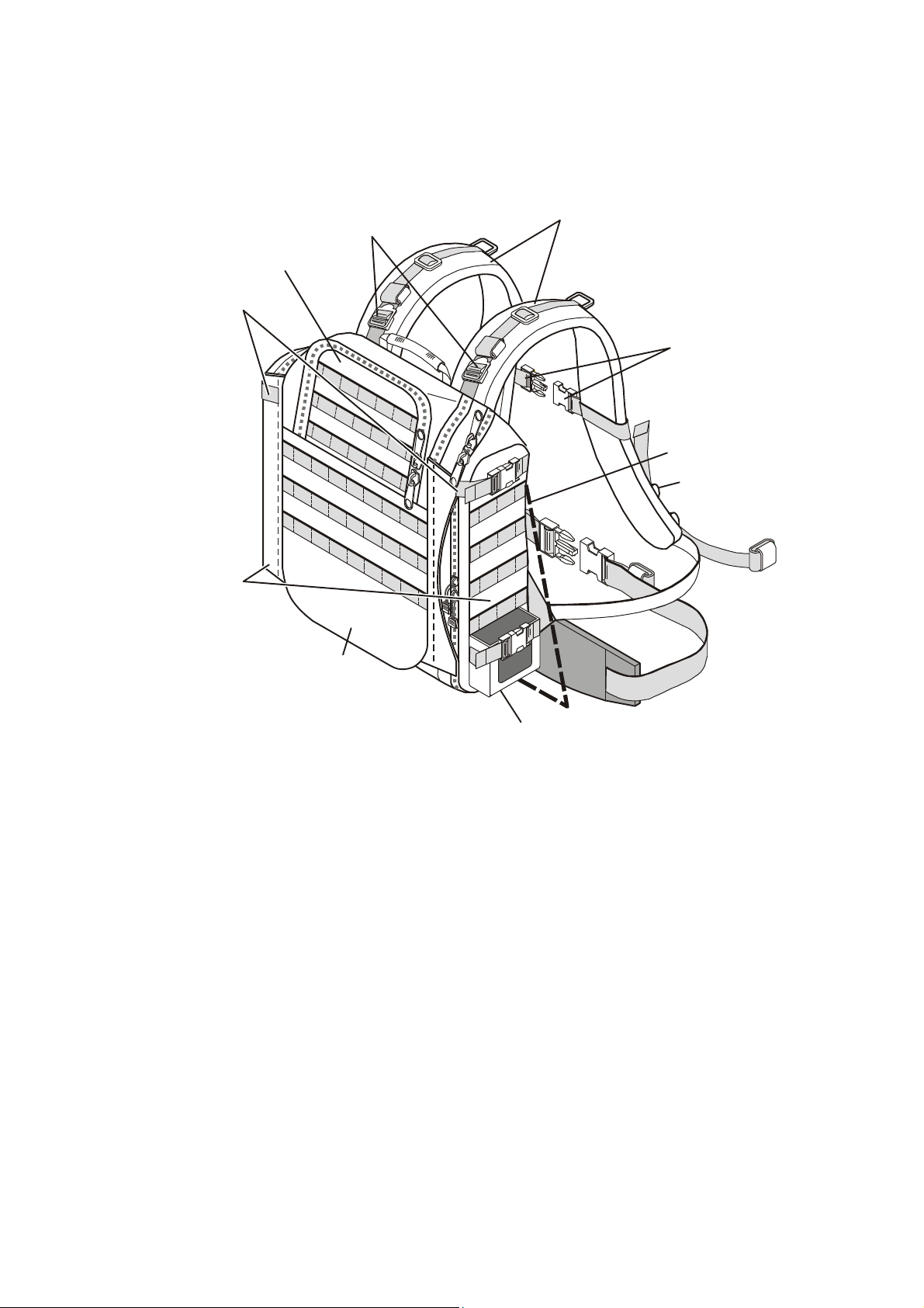
2-3.2 Installation in Carrying Harness
2-3.2.1 Familiarization with Carrying Harness
Figure 2-2 shows a general front view of the closed carrying harness. The harness can be weared on
the operator’s back, or placed on the ground, using the rear support to hold it in a vertical position.
Buckles
Top Protection
Flap
Attach GPS
Antenna Adapter
to one
of these Strapss
Breast Strap
Rear Support
Adjustment
Buckles
Side Accessories
Pouches
Waist
Strap
Flap
Loudspeaker
Figure 2-2. Carrying Harness, Front View (Closed)
The carrying harness transceiver compartment is closed by a front flap, which can be unzipped and
raised as shown in Figure 2-3. This provides full access to the interior of the carrying harness for
installing the transceiver, or retrieving stored items (spare battery, charger, cables, etc.). Additional
storage pouches for large accessories, e.g., folded whip antenna, handset, etc., are located on the sides
of the carrying harness. The optional GPS antenna (mounted on the adapter, AD-1000P) can be
attached to one of the top side straps (either on the left or right hand side of the harness). The optional
portable loudspeaker, LS-108M, can be inserted in a special pocket at the right-hand side, or attached
with a strap to the harness. During operations, the audio accessory (handset or microphone) can be
attached with a strap to the front side of the desired shoulder strap.
In addition to the front flap, the carrying harness has a top protection flap: when the front flap is
closed, it is possible to open the top flap to gain access to the Micom front panel and to most of the
stored items.
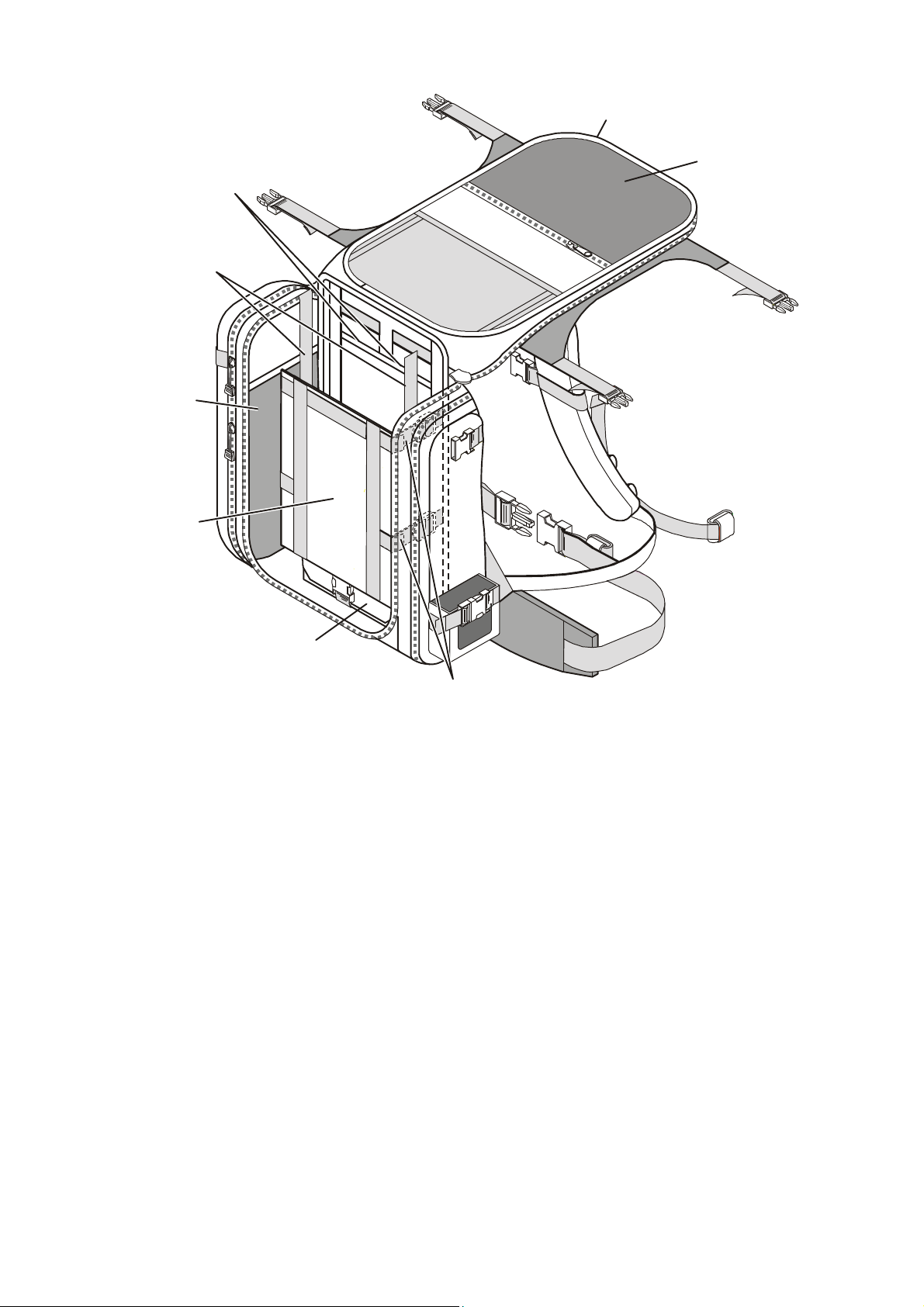
Figure 2-3 shows the carrying harness with the front flap open. Note the internal storage pockets, and
in particular the spare battery compartment. The transceiver, with battery, is installed in the
compartment located above the spare battery storage, behind a restrainer plate. After the transceiver is
in place, the restrainer is pressed against the transceiver body by tightening the four side restraining
straps. Two additional top restraining straps, passing along the sides of the transceiver, are attached to
the handles, to prevent vertical movement. After the transceiver is secured, the front flap can be
closed.
2-3
Page 22
OM-E 2072-09287-00
Transceiver Restraining
Front Flap
Passthrough Slots
for Cables
Top Transceiver
Restraining Straps
Internal
Storage
Pockets
in Open Position
Cable Storage
Pocket
Restrainer
Spare Battery
Compartment
Side Straps
(4 places)
Figure 2-3. Carrying Harness with Front Flaps Raised
2-3.2.2 Installation Procedure
1. Place the carrying harness on a clean, level surface.
2. Release the four straps (two on each side).
3. Unzip the front flap, and then raise the flap as shown in Figure 2-4.
4. If necessary, store a spare battery in its storage compartment.
5. Release the two top transceiver restraining straps, and the four side restraining straps.
6. Orient the transceiver as shown in Figure 2-4, and then place it in position, behind the restrainer
plate.
2-4
Page 23
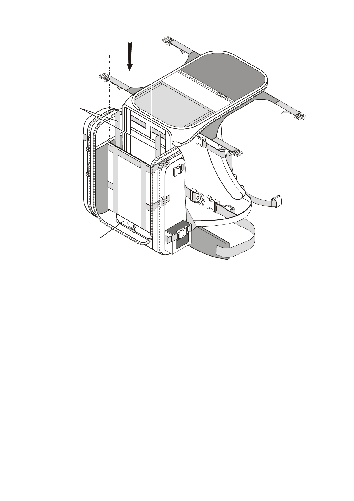
Front Flap
in Open Position
2. Insert Transceiver
1. Open Top and
(6 places)
OM-E 2072-09287-00
Insert Spare Battery
in Storage Compartment
Figure 2-4. Installing Transceiver in Carrying Harness
7. Fasten the four transceiver restraining straps to secure the transceiver behind the restrainer plate.
8. Pass each top transceiver restraining strap over the corresponding transceiver handle, and fasten
the straps. See detail of transceiver installed in harness in Figure 2-5.
9. Ensure all transceiver restraining straps are tight.
10. Place all the items to be stored inside the carrying harness in the corresponding storage pockets.
11. Close the front flap and secure with its zipper.
12. Insert all the items to be stored in the side accessories pouches, close the pouches, and then
secure the pouches with the corresponding straps.
2-5
Page 24
OM-E 2072-09287-00
Support Strap
Top Restraining Straps
(2 places)
Figure 2-5. Detail of Transceiver in its Carrying Harness
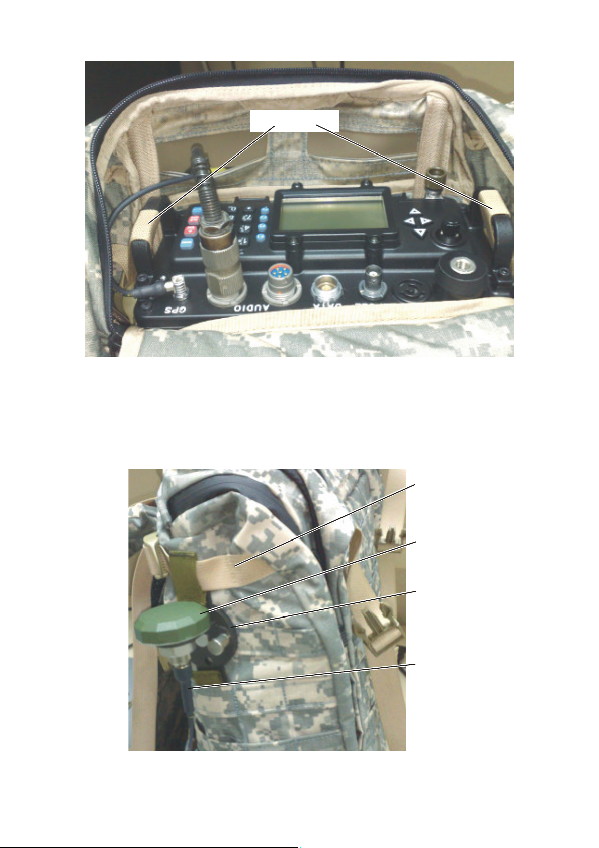
2-3.2.3 Installation of Optional AD-1000P and GPS Antenna AT-1000
1. If the optional GPS receiver will be in use, insert the GPS support strap in the top loop of the
optional AD-1000P, and slide the AD-1000P in place.
2. Insert the other end of the AD-1000P in a suitable slot, as shown in Figure 2-6, and then secure
the AD-1000P by fastening the strap.
GPS Antenna
AT-1000
AD-1000P
CG-5602
Figure 2-6. GPS Antenna Installed on Harness
2-6
Page 25
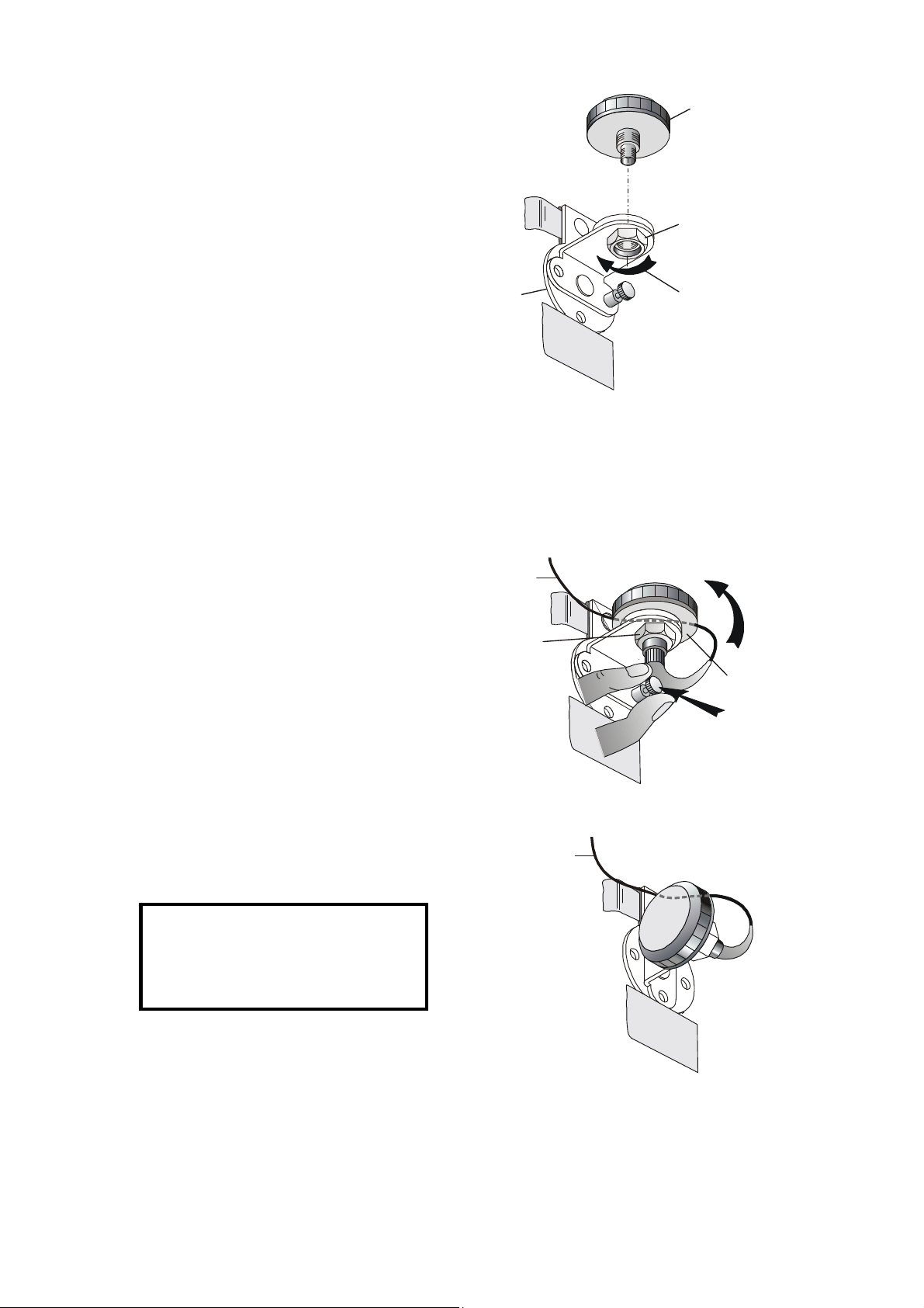
OM-E 2072-09287-00
Turn Clockwise to
AT-1000
Captive
Locking Nut
2. Turn GPS Antenna
AT-1000
To GPS Connector
1. Pull Lock Pin Out
To GPS Connector
1. Insert the threaded stud of the AT-1000 in
the AD-1000P hole.
2. Turn the captive nut of the AD-1000P
clockwise to fasten the AT-1000 to the
adapter.
3. Remove the cover from the GPS
connector of the Micom.
4. Connect the TNC connector of the
CG-5602 cable to the AT-1000 connector,
and tighten the connector.
AD-1000P
Fasten Antenna
5. Plug the connector at the other CG-5602
end into the Micom GPS connector.
2-3.2.4 Orienting the GPS Antenna Toward the Sky
When the GPS function is used, the GPS antenna must point toward the sky at all times.
The AD-1000P has two positions:
• Standing position: directs the antenna toward the sky when the Micom operator stands or walks.
• Prone position: directs the antenna toward the sky when the Micom operator lays on the ground.
3. Release Pin
To rotate the GPS antenna from the standing
CG-5602
AD-1000P
position to the prone position:
1. Pull the AD-1000P lock pin out.
2. Turn the GPS antenna counter-clockwise.
3. Release the lock pin, and make sure it snaps
into the corresponding hole locking the antenna
and preventing it from rotating.
The same procedure is used to return the GPS
antenna to the standing position.
GPS Antenna in Standing Position
CG-5602
CAUTION
Make sure that the CG-5602 cable is
not pulled nor stressed when the
AD-1000P is rotated.
GPS Antenna in Prone Position
2-3.3 Installation of Whip Antenna
Before starting make sure that the top protection flap is fully open.
2-7
Page 26

OM-E 2072-09287-00
To install the antenna:
1. Remove cover from the WHIP connector on the Micom front panel.
2. Visually check the connector for dirt or damage. Clean if necessary.
3. Screw antenna support AB-591 into the Micom WHIP connector. Tighten by hand only.
4. Extend the whip, and secure all sections by inserting them one into the other by hand.
5. Screw whip antenna sections into antenna support, AB-591.
NOTE
When the radio set is not in use, you may fold the antenna without
disconnecting it from the WHIP connector. In this case, fasten the
folded sections using the safety belt supplied with the antenna. Before
starting transmission, make sure to release the safety belt and extend
the antennas.
To remove the whip antenna, perform the above tasks in the reverse order.
CAUTION
When folding the whip, always start with the upper section, otherwise
it may be damaged.
2-3.4 Connection of Audio Accessories
Connect the handset, FMN5501, to either of the AUDIO connectors on the front panel of the Micom.
You may secure the handset to the front side of a supporting strap.
If the optional LS-108M loudspeaker is used, insert it in the pocket and secure it with the straps, or
attach it with a strap passing through its top and bottom hooks. Connect the loudspeaker cable to one
of the AUDIO connectors on the front panel of the Micom. Route the audio cables through the
dedicated passthrough slots on the back of the harness.
2-3.5 Wearing Backpack Carrying Harness
To wear backpack:
• Put harness on your back by inserting arms through shoulder straps.
• Tighten shoulder straps if necessary by adjusting the strap buckles.
• Buckle waist straps to belt and adjust to size.
• Adjust the breast strap length and then attach the strap.
At this stage, the Micom Pathfinder is ready for use as a manpack radio set.
2-3.6 Operating Micom Pathfinder on Ground
To operate the Micom Pathfinder on the ground, place the backpack on a flat, dry area, and deploy the
rear support to stabilize the harness in a standing position.
For safety, and to achieve best perform, ground the Micom Pathfinder: drive the grounding spike into
the ground close to the radio, and then connect the grounding strap between the front panel grounding
post and the grounding spike.
2-4. USING THE FAA5548 TACTICAL DIPOLE ANTENNA
In static operation, the Micom Pathfinder can be used with an FAA5548 tactical dipole antenna. Refer
to Appendix B for FAA5548 installation and operation instructions.
2-8
Page 27
OM-E 2072-09287-00
GP S
1
?@A
G
J
T
D
M
W
P
B
H
K
U
E
N
X
Q
C
I
L
V
F
O
YRZ
S
/
2
3
456
789
0
#
*
ALM
GPS
P.
SC
MENU
A U D IO
ON/OFF & Volume Control
AUDIO Connectors
Tx Indicator
transmitting
CHAPTER 3
OPERATING PROCEDURES
3-1. SCOPE
This Chapter describes the Micom Pathfinder controls, indicators and connectors, and explains its
specific operating procedures. The Chapter is organized as follows:
• information needed to familiarize with the equipment panels – para. 3-2
• procedures for using the Micom Pathfinder keypad and display to perform any desired task –
para. 3-3, and para. 3-10, 3-11
• how to start using a radio ready for operation (i.e., a radio installed in accordance with Chapter
2 and programmed in accordance with Chapter 4) – para. 3-5
• specific operating procedures for each main operating mode of the radio:
Channel mode – para. 3-6
Frequency mode – para. 3-7
Scan mode – para. 3-8
ALE mode – para. 3-12
• procedures for using the GPS receiver – para. 3-9.
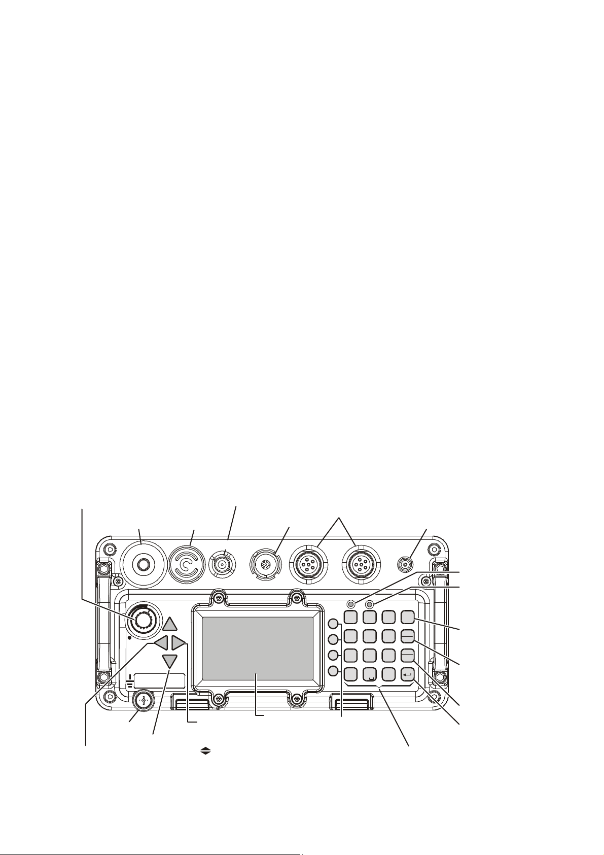
3-2. MICOM CONTROLS, INDICATORS AND CONNECTORS
Figure 3-1 explains the functions of the front panel controls, connectors and indicators.
Turns radio on and off and
controls the speaker volume
WHIP Connector
(for FAD5530)
W H IP
OFF
DIPOLE Connector
(for FAA5548)
Internal
Speaker
D I P O LE
DATA
Connector
D AT A
Connectors for
external speaker
and handset
F1
F2
F3
F4
Connector
for GPS
Antenna
E
Not used
Lights when
radio is
MENU Key
Displays the
main menu
ESC Key
Cancels last action
and reverts to the
previous screen
Grounding
Move
cursor to
the left
Post
Scrolling Keys
Display
Function Keys
Activates the function
or selects the option
displayed next to
each key
A set of keys used to
enter alphanumeric data
Keypad
Up/Down
Used to scroll
values
MORE Key
Displays additional
menu options when
appear in the display.
Also moves cursor
to the right
Figure 3-1. Micom Front Panel Controls, Indicators and Connectors
Not used
ENTER Key
Saves the selection
and/or value
3-1
Page 28
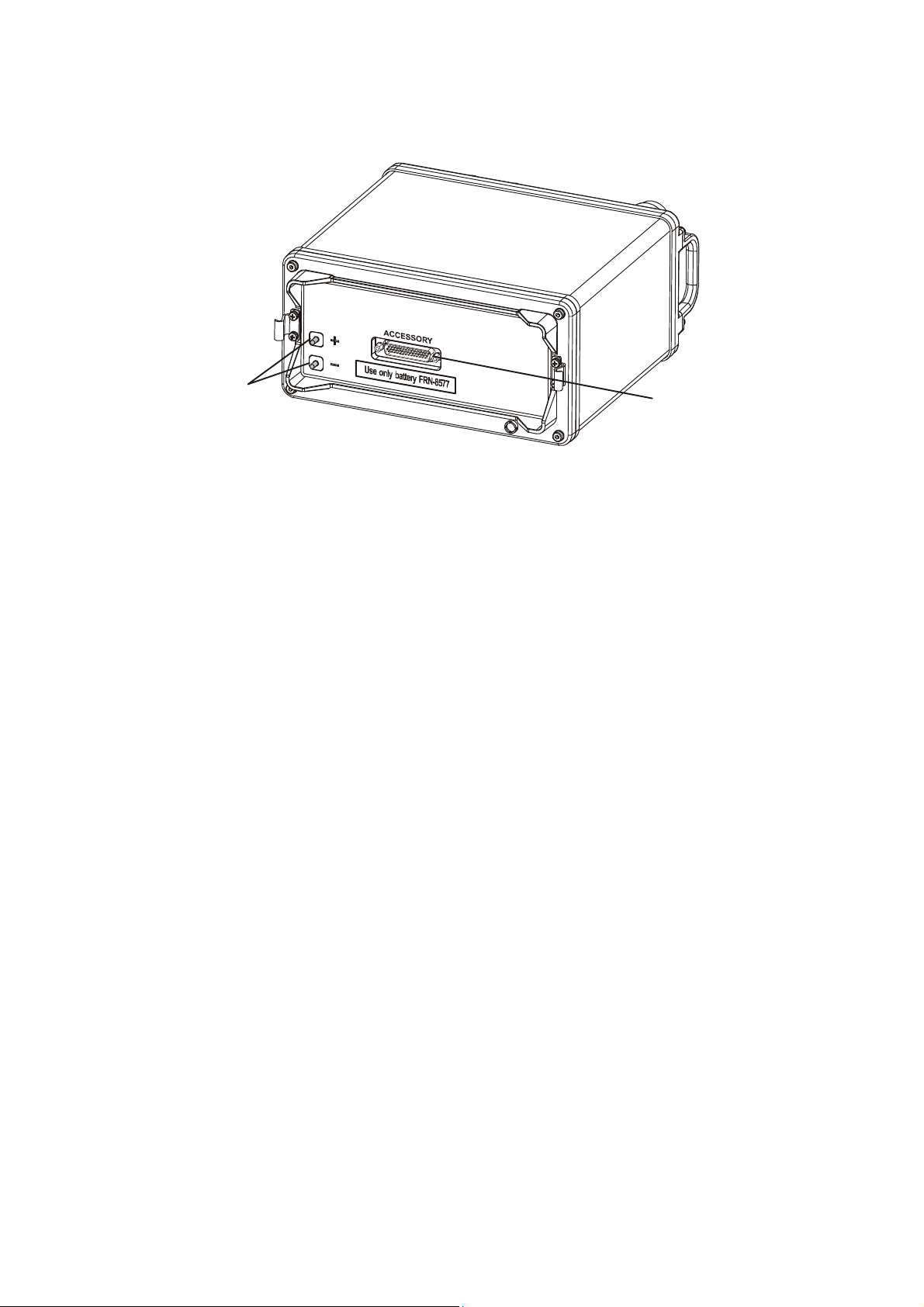
OM-E 2072-09287-00
ACCESSORY
Connector
Figure 3-2 identifies the connectors located on the Micom rear side. The rear side includes a two-pin
connector, for connecting the power, and a 44-pin connector. The 44-pin connector is normally
covered by the battery, and therefore it is not available for use in manpacks.
Battery
Connector
Figure 3-2. MICOM Rear Side Connectors
3-2
Page 29
OM-E 2072-09287-00
PWR
MODE
6
754
3
3-3. FAMILIARIZATION WITH MICOM OPERATING PROCEDURES
This section provides general procedures that will help you start using your radio and get the most of
its advanced features. Most of the activities that can be performed by you (selection of operating mode,
programming, testing, etc.) are done using the keypad together with the navigation and function keys,
and the front panel display.
To simplify operation, Micom function keys operate as soft keys and therefore they permit you control
the radio simply and efficiently, using a menu-driven mode that guides you and helps you make the
required selections. “Menu-driven” simply means that whenever you must select a parameter, an
operating mode, etc., you select it from a list of allowed values displayed on the front panel display,
thereby reducing the chance of error:
• To make a selection, you use navigation keys to reach the desired parameter value or action, and
then confirm the selection by pressing the ENTER key.
• To go back to previous options, or cancel the current selection or action, press the ESC
P.
E
SC
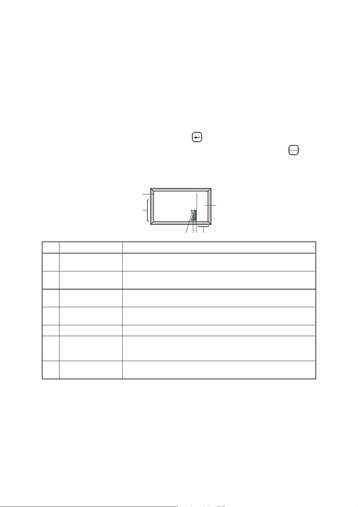
3-3.1 Display Functions
3-3.1.1 Display Organization
1
CH 6
F 16,000.00
2
SQ BW3.3
AGC
NF
USB
NB
CLAR
AGC
BW
I
No. Designation Description
1 Mode indicator Indicates the current working mode (e.g., channel, frequency, ALE,
etc.) or the action being performed (e.g., programming, testing, etc.)
2 Work area Displays information on the current working mode, the main operating
parameters, the active options, status, etc.
3 Transmit level
indicator
4 Receive level
indicator
In the transmit mode, displays the relative transmit power
In the receive mode, displays the relative received signal strength
key.
5 Tx bar Appears when the radio is transmitting
6 More options Icon The presence of this icon indicates that more options can be displayed
in the options area. When this icon appears, press the MORE key to
see menu options
7 Options display area Displays a list of options you can select, by pressing the corresponding
key, in the current working mode
3-3
Page 30
OM-E 2072-09287-00
D
M
W
E
N
X
F
O
YRZ
3
6
9
#
ALM
GPS
P.
SC
3-3.1.2 Mode and Function Indications
The following indications may appear in the work area of the LCD display, to indicate the selected
mode or functions that are active.
Indication
USB
LSB
SQ
MON
AGC
BW
NB
CLAR
NF
Using upper sideband for transmission and reception
Using lower sideband for transmission and reception
Squelch is active: the speaker is turned on only when the radio identifies speech, to
prevent reception noise from being heard
When using ALE, indicates that the speaker is normally off, and is automatically
turned on when the link is established
Non-standard AGC mode (AGC off, or fast AGC) has been selected
Non-standard bandwidth has been selected (the bandwidth appears next to the BW
indicator, for example, 3.3 (3.3 kHz) in the screen shown above)
Noise blanker is active
Clarifier is active (meaning that you selected a frequency deviating from the nominal
channel frequency)
Notch filter is active
3-3.1.3 RF Level Indications
Indication Meaning
Meaning
Strong received signal
Weak received signal
– Full transmit power
– Relative transmit power
– Low transmit power
– Reflected power
Received RF signal strength indication, displayed when the radio is
in the receive mode. The height provides a relative indication,
which may fluctuate as a result of fading, etc.
Transmit bar, appears when the radio is switched to the transmit
mode (for example, when the PTT is pressed). Its length indicates
the maximum radio transmit power in the selected mode (MAX,
HIGH, MED or LO). The triangle height indicates the instantaneous
relative transmit output power, and therefore it fluctuates as a result
of modulation.
The relative reflected power is indicated by the base line: its length
indicates the fraction of power reflected because of antenna VSWR
(the length should be small relative to the total height of the
transmit bar, which is proportional to the forward power)
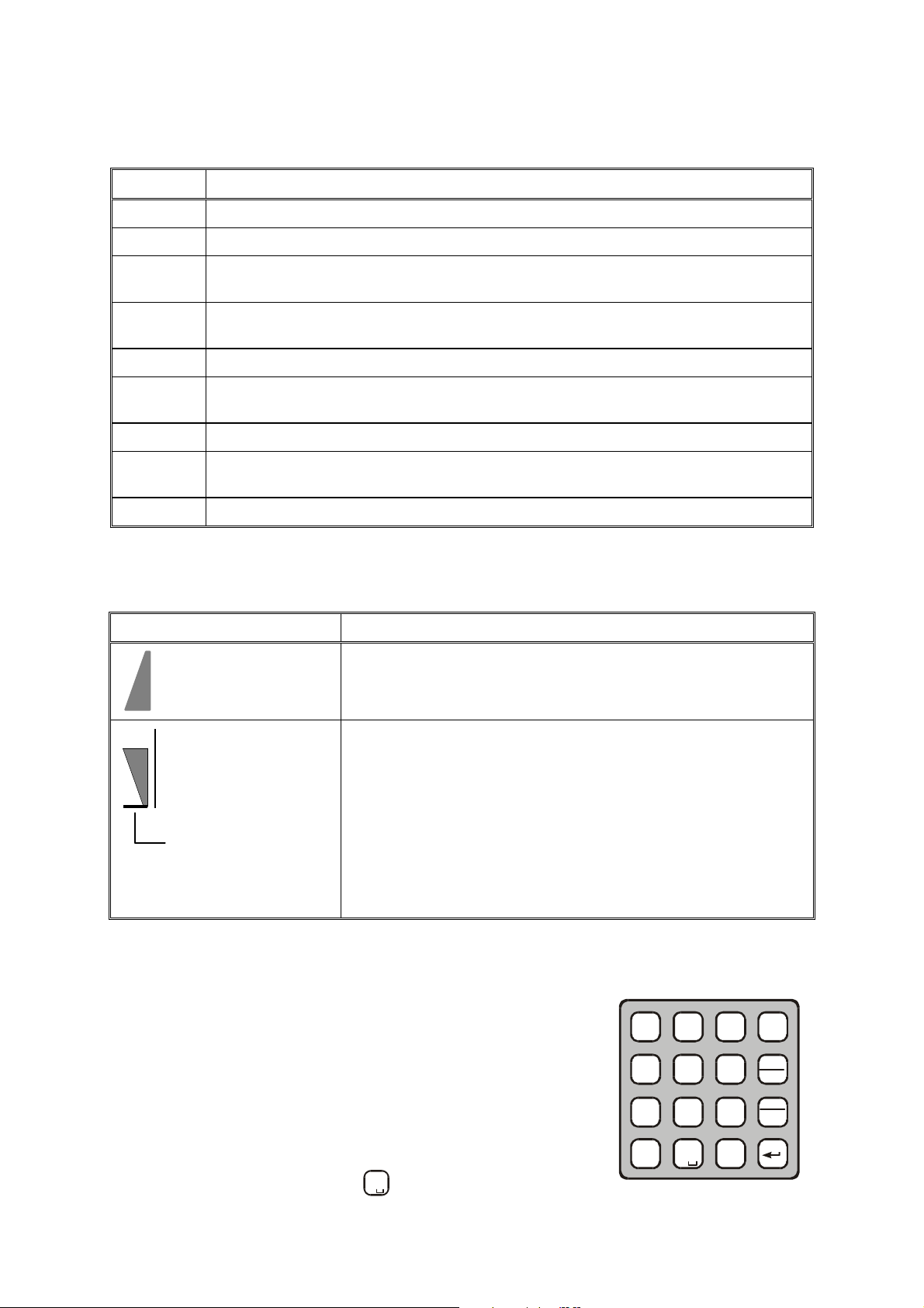
3-3.1.4 Using the Keypad
Each key is imprinted with a numeral and several letters.
These characters are accessed in clockwise order, as follows:
• A single key press enters the numeral
• Two consecutive key presses enter the first letter
• Three consecutive key presses enter the second letter
• Four consecutive key presses enter the third letter.
?
@
1
/
G J
H K
4
I L
P
7
S
A
B
2
C
5
T
Q
U
8
V
MENU
E
• Five consecutive key presses enter the fourth letter.
• To enter a blank space, press
3-4
0
twice.
*
0
Page 31

OM-E 2072-09287-00
RAD
ALE
LANG
F1
F2
F4
F3
Up
More
Down
When entering frequencies, use the * key as a decimal point, if needed. In the ALE mode, the *
key is also used to enter the wild-card character (? or @).
To enter the ampersand @ symbol, press the
key twice.
#
Example: To enter a number in a field, or edit (change) the number, you type the desired digits on the
keypad.
Example: To enter an alphanumeric string in a field, or edit a string, you type the desired
alphanumeric character by pressing the appropriate key several times in sequence. For example, to
enter “MIKE 01”:
M
Press
Press
Press
Press
N
twice (for the letter M).
6
O
G
H
four times (for the letter I).
4
I
J
K
three times (for the letter K).
5
L
D
E
three times (for the letter E).
3
F
Press 0 twice (for the blank space).
Press 0 once (for the numeral 0).
?
Press
3-3.1.5 Function Keys
@
once (for the numeral 1).
1
/
The function keys F1, F2, F3 and F4 appearing next to the display are
soft keys used to select options which depend on the current radio
mode. The current function of each key is shown in the options area of
PROG
the display, next to the key. For example, on the PROG screen you can
press F2 to start programming the ALE parameters.
If a certain function key is not used, no label appears next to the key
(see for example F4), and pressing that key has no effect.
3-3.1.6 Options Scroll (MORE) Key
When more than four options are available in the options area of the display, press the MORE key to
display the additional options.
To return to the first option, press the ESC key.
3-3.1.7 Up/Down Scroll Keys
The up and down scroll keys are used to scroll between values that are already
programmed into the radio. For example:
• In the Channel mode, pressing the up or down scroll key once lets you
view the previous, respectively next, programmed channel. Pressing
either key continuously scrolls the channels in the selected direction.
• In the Frequency mode, you can change the frequency in the
corresponding direction.
• In the radio Programming mode, you can use these keys to scroll
among the programmable parameters.
• When displaying GPS data, you can use these keys to toggle the display
format.
3-5
Page 32

OM-E 2072-09287-00
ADT - 9 SEC
ALE - NO
EDIT
ERAS
AMD 0
3-3.1.8 Selection from List of Predetermined Values
When the parameter you want to select can assume only one of several
predetermined values, you select the desired value by pressing the function
keys:
• F1 enters the lowest possible value (or OFF)
• F4 enters the highest possible value
• F2 and F3 increment or decrement the value. When you reach either
end, the corresponding key disappears.
You cannot use the keypad to enter a value for such parameters.
3-3.1.9 Toggle Mode
When the function being set can only be toggled on or off, one function key
will be marked YES and another NO.
To expedite turning on and off often-used functions (for example, turn the
squelch on or off) only one key is used. In this case, just press the key
assigned to the function to be toggled: the new state is shown for a few
seconds, and then disappears as it takes effect immediately.
3-3.1.10 Alphanumeric Edit Mode
PROG
PROG
1
<--
-->
10
YES
NO
When you need to enter an alphanumeric string in a field, or edit a string, you type the desired
alphanumeric character on the keypad. A blinking cursor _ indicates the location being edited.
In addition, the following function keys are available:
SAVE (F1)
<−−
<−− (F2)
<−−<−−
−−>
−−> (F3)
−−> −−>
CLR (F4)
Saves editing changes (equivalent to pressing the ENTER key).
Used to move the cursor backwards and forwards. When you reach either end, the
corresponding key disappears.
Pressing this key momentarily erases the digit/letter at which the cursor is presently
located, and shifts the entire field one place to the left.
Press this key continuously clears the entire field.
3-3.1.11 Numeric Edit Mode
When you need to enter a number in a field, or edit the number, you type the desired digits on the
keypad. A blinking cursor _ indicates the location being edited.
In addition, the following function keys are available:
BACK (F3)
CLR (F4)
Erases the last digit.
Erases all newly entered digits and restores the original value.
3-3.1.12 View Mode
When the string to be displayed is longer than the number of characters
that fit in one line (for instance, with long addresses or messages), the
view mode enables scrolling to the rest of the string.
The view mode is indicated by the symbol < − >
< − > next to one of the
< − >< − >
function keys.
3-6
01 AMD MESS
<->
Page 33

OM-E 2072-09287-00
Scroll one character to the left or right, respectively. If
you press either key continuously, the scrolling
HOME
AMD 0
MESSA
When you press < − >
HOME (F1)
<−−
<−− (F2)
<−−<−−
−−>
−−> (F3)
−−> −−>
END (F4)
< − >, the key functions change:
< − >< − >
Scrolls to display the first character of the string.
1 AMD
continues at a rate of four characters per second.
Scrolls to display the last character of the string.
<--
-->
END
When you reach the beginning of the string, the HOME (F1) and <−−
whereas when you reach the end of the string, the −−>
3-3.1.13 Message Attached Alert
−−> (F3) and END (F4) function keys disappear.
−−> −−>
When a message is attached to the received call (an option available for
ALE calls, even if you are using the Channel mode), an exclamation
sign ! appears to the left of the originating station name.
<−− (F2) function keys disappear,
<−−<−−
FROM
!ABC
You can view the message contents after you accept the call.
3-3.2 Audible Indications
The user can configure the radio to generate audible tones to indicate events related to the radio
operating conditions. The tone volume, low or high, may also be set using the MRC, or by
programming from the front panel.
Event Description
Valid key pressing Beep sounds when a key is pressed, to indicate that the key pressing has been
accepted. No beep – no action.
PTT release A beep sounds on the remote radio to indicate that the local PTT button has
been released.
ALE alerts During ALE operation, beeps alert you to events you should be aware of, e.g.,
link establishment/disconnection, etc.
3-7
Page 34

OM-E 2072-09287-00
CHAN
FREQ
LOCK
PROG
SPKR
LOCK
PROG
RAD
ALE
LANG
ENGLISH
3-4. MENU STRUCTURE
The menu is used to select and control what you want your radio to do.
3-4.1 Displaying the Main Menu
To display the menu:
1. Press MENU to display the first part of the Menu screen.
You can press the MENU key at any time during any sequence of
operations: that sequence is then discontinued and the menu screen is
immediately displayed.
NOTE
The menu structure depends on the operating mode selected
by the user. For example, when the ALE function is not used,
the third item is either SCAN.
2. Press MORE to scroll to the second part of the Menu screen.
Press MORE again to scroll to the third part of the Menu screen.
3. To select any item, press the function key next to it.
MENU
MENU
MENU
I
ALE
BIT
I
PSW
DIM
I
To exit the menu and return to regular radio operations (e.g., CHAN or FREQ):
4. Press the ESC key. The deeper you are in the menu, the more times you need to press ESC.
3-4.1.1 Selecting the Display Language
MENU
5. Display the second part of the Menu screen as explained above.
PROG
6. Press PROG (F2) to enter the Programming mode.
7. Press the function key next to the desired language.
LANG
8. Confirm the selection by pressing the ENTER key.
I
PSW
DIM
ENGL
FREN
ESPA
3-8
Page 35

3-4.2 What you can Select on the Main Menu
to find details on the selections available on the CHAN
OM-E 2072-09287-00
Main Menu
CHAN
1
2
3
4
FREQ
SMPX
DPLX
RXO
TXO
ALE (PROG) = YES ALE (PROG) = NO
ALE
NET
or
ENTER
NO
SCAN
STOP
SLOW
FAST
GRP
More More
BIT
FULL
CHAN
L.RF
A
B
C
D
LOCK
LOCK
PSW
PROG
RAD
ALE
LANG
VCD
PSW
ENGLISH
FRENCH
ESPA
OPTION
PSW
OLD
DIM
LEVEL
0 1 2 3
Figure 3-3. Main Menu
Use the following description with Figure 3-3, which shows the details of the main menu.
Menu item ... and its purpose
CHAN
Channel mode: the radio uses a set of preset parameters. Up to 200 sets of parameters
can be defined and stored in the Micom, where each set is assigned a channel number (1
to 200). You can use Figure 3-4
menu.
FREQ
Frequency mode: you can select manually the frequency (free tune mode) and the other
parameters to be used. You can use Figure 3-5 to find details on the selections available
on the FREQ menu.
SPKR
ON
OFF
ALE
ALE mode: when you want to call other radio, the radio automatically sets up a link on
the best free frequency that can be found. You can also call specific radio sets, a group
of radio, or broadcast to all the radio sets. The sets of parameters needed for this
operation mode are stored under net numbers (1 to 20), the radio sets are identified by
addresses stored by the radio in a directory supporting up to 100 addresses.
SCAN
SCAN mode: when neither the ALE, nor the CCIR mode, is used, you can define a set
of channels to be scanned before starting a call. The scan parameters are always loaded
by the MRC together with the other operational parameters, and cannot be changed
using the Micom panel.
BIT
LOCK
PROG
BIT mode: lets you check that the Micom is OK.
Lock the radio to prevent unauthorized use. To lock and unlock, you enter a password.
Programming mode: lets you program (select and store) the required parameters. Refer
to Chapter 4 for details on the selections available on the PROG menu.
PSW
DIM
SPKR
3-4.3 Notational Conventions
Used to change the password.
Used to adjust LCD lighting.
Used to enable/disable the internal speaker.
In this manual, the following conventions are used to simplify the description of the steps you need to
carry out actions using the keys and the LCD:
When a procedure begins with a sequence of steps, that sequence is represented in an abbreviated
format, with the > symbol indicating the next key to be pressed.
For instance, the following represents a sequence of steps that involves five key pressings:
MENU > MORE > PROG (F2) > RAD (F1) > CHAN (F1).
3-9
Page 36

OM-E 2072-09287-00
SELF TEST
BAND
14,000.00
3-5. GETTING STARTED
This section provides basic operating instructions: it covers issues such as turning the radio on and off,
preparing it for operation in your particular environment, receiving and transmitting, selecting a
channel or a frequency, etc.
NOTES
• The information needed to use Micom in the ALE mode appears in
para. 3-12.
• The information needed to use the Micom GPS receiver appears in
para. 3-9.
You can use these instructions to start using your Micom radio. To become familiar with all the radio
capabilities and features, refer to the following sections. In most cases, the radio reaches you after
being configured for use in your radio net. However, if you need to make changes, refer to Chapter 4.
3-5.1 Turning the Radio On and Off
To turn the radio on:
1. Turn the ON/OFF/VOLUME knob clockwise to midrange. You
may hear a click as the radio is turned on.
2. The display turns on and shows SELF TEST for a few seconds.
NOTE
If the display is too dim, adjust its brightness using
MENU > MORE > DIM.
3. If the self-test procedure is successfully completed, the radio
automatically resumes operation in the last used mode (CHAN,
FREQ, ALE, or SCAN).
4. If necessary, adjust the volume control for your convenience.
NOTE
To increase the battery life, Micom Pathfinder has an automatic
dimmer feature. The automatic dimmer feature turns the lighting
off (that is, automatically sets the dimmer level to 0) when the
radio is not in use for 20 seconds. However, as soon as you
press any key or the PTT, the lighting is automatically turned on
at the operator-selected brightness, and remains ON for 20
seconds after the last key pressing, or after the PTT is released.
If automatic dimming is enabled (DIM is YES), the display may
turn off after a few seconds of inactivity. To cancel this feature,
use MENU > MORE > PROG > RAD > PRMT > DIM to select
NO for DIM.
CH 1
F
SQ
USB
SQ
DSP
I
If a problem is detected during self-test, the display shows ERR and a code number, followed by a
concise description of the error (if the description does not fit in one row, its parts alternate in the
display). If the detected problem does not prevent using the radio, press EXIT to cancel the display
and continue.
3-10
Page 37

OM-E 2072-09287-00
To turn the radio off:
Turn the ON/OFF/VOLUME knob counterclockwise beyond the detent. You
may hear a click as the radio is turned off.
The display turns blank.
3-5.2 Preparation for Operation
3-5.2.1 Antenna Type Selection
After turning the Micom Pathfinder on, it is necessary to check the antenna type, and change it as
necessary.
Use the following procedure to select the antenna type:
1. Press the MENU key, and scroll to MENU > MORE > PROG > RAD, to display the RADIO
PROGRAMMING screen.
2. Navigate to the last item (next to F4) on the RADIO PROGRAMMING screen, which shows
the current antenna type:
• WHI – whip, for example, FAD5530. In this case, the internal antenna tuner is automatically
enabled (select ON on the MENU>MORE>PROG>ACC TUNE screen) and it is not
possible to disable the tuner as long as the selected antenna is WHI.
• DIP – dipole, for example, FAA5548. When you select DIP, the internal antenna tuner is
disabled by default (NONE on the MENU>MORE>PROG>ACC TUNE screen), however
you can enable the tuner if necessary (for example, it is recommended to enable the tuner
when using a long wire antenna configuration for operation over a wide range of frequencies,
for example, in the ALE mode).
If necessary, press F4 to toggle the selection.
NOTE
When the tuner is enabled, you will see TUNE on the default CH
(channel) mode screen.
In addition, when you change the operating channel, you will see for a
few seconds a ...TUNE... message on the screen: this indicates that
the tuner adjusts automatically to operation on the new frequency.
3. If you select DIP and want to enable the tuner, navigate to MENU>MORE>PROG>ACC, and
press F2 (TUNE). Note however that this setting is lost when Micom Pathfinder is turned off.
Therefore, the next time Micom Pathfinder is powered up you must be select TUNE again if the
tuner must be used when the antenna is set to DIP.
At this stage, you can start using Micom Pathfinder in accordance with the standard operating
procedures.
3-5.2.2 Enable/Disable the Internal Loudspeaker
When you do not want to use the internal loudspeaker (for example, when connecting the external
loudspeaker, LS-108M), use the following procedure:
1. Press the MENU key, and press the MORE key twice to reach SPKR. The screen displays the
current state, SPEAKER OFF or SPEAKER ON.
2. To toggle the state, press F3. The screen displays the new state.
3-11
Page 38

OM-E 2072-09287-00
3-5.2.3 Radio Filter Bandwidth and Service Type
The radio filter bandwidth must be selected in accordance with the type of signal to be transmitted and
received. For the transmit mode, the type of signal is identified by detecting the active PTT signal,
which is one of the following:
• MIC PTT – PTT from the microphone connected to the front panel AUDIO connector;
transmits your voice.
• Data PTT – PTT from a data device, for example, a modem, connected to the radio set through
the DATA connector; it causes the radio to switch to the data mode and transmit the modem
signal.
The radio operating mode is automatically adapted for best performance with the signal expected for
the detected PTT type.
A default filter bandwidth can be configured for each channel using MENU > MORE > PROG >
RAD > CHAN (if no particular filter is set for the current channel, the radio retains the previously
used filter). When a new type of call is received or sent, the bandwidth filter changes automatically,
depending on the PTT source (voice, data or CW), and the programmed bandwidth for the channel
being used.
Bandwidth set to: Service type: Filter changes after:
2.1 kHz Data First data PTT
2.7 kHz Voice First microphone PTT
3.0 kHz Data First data PTT
3.3 kHz High speed data First data PTT
CW Morse First CW PTT
LSM Low speed data First data PTT
NOTE
When the filter bandwidth is set to CW, the following CW filter
bandwidths can be configured in the Programming mode using
MENU > MORE > PROG > RAD > PRMT: 0.25, 0.5 or 0.8 (kHz).
3-12
Page 39

OM-E 2072-09287-00
Tx Bar
Reflected
Power
Strong received signal
3-5.3 Transmitting and Receiving
CAUTION
Do not transmit with radio on your back. Place radio on ground before
starting transmit/receive communication, and connect it to the
grounding spike in accordance with Chapter 2.
To transmit a voice message:
Press and hold down the Push-to-Talk (PTT) button of the microphone, and speak slowly and clearly
after the channel is clear.
You should hear a sidetone, which verifies that your radio transmits normally.
NOTE
No sidetone is heard when using the optional
vocoder.
The display changes to show the TX bar, together with indications of
forward and reflected power.
During normal speech, these indications fluctuate in accordance with
your voice.
To receive calls:
When the radio identifies a call addressed to it, it sounds a beep and if
it is a voice message – you start hearing it in the speaker. The display
shows the name of the calling station (blinking) and the call type. The
display now shows the RX indication, which is proportional to the
received signal strength.
Forward
Power
Weak received signal
3-13
Page 40

OM-E 2072-09287-00
3-6. USING THE CHANNEL MODE
The Channel mode is used to operate on a channel already programmed in the Micom.
The following sections describe how to use the Channel mode.
3-6.1 Channel Mode Options
In the Channel mode, you can operate a variety of functions and options which can help eliminate
noise, or otherwise assist reception and/or transmission.
The structure of the CHAN menu is shown in Figure 3-4.
CH 6
CH 6
CH 6CH 6
FFFF
16,000.00
16,000.00
16,000.0016,000.00
USB
BAND
I
SQ
DSP
More
VCD
Option
PVT#
DGTL
CLR
TXM
For duplex
and TX only
channels
More
Only for ALE Enabled
More
BAND
LSB
USB
SQ
DSP PWR
ON
OFF
CLAR
NF
CLIP
NB
ATTN
.
.
.
.
.
.
.
.
.
.
.
.
-200
.
.
.
.
OFF
.
.
.
.
+200
ON
OFF
ON
OFF
ON
OFF
MODE AGC
LOW
MED
HIGH
MAX
SSB
AME
PLT
SLOW
FAST
OFF
BW
2.1
2.7
3.0
3.3
LSM
CW
RCLV
GPS
Option
More
Figure 3-4. Channel (CHAN) Menu
NOTES
• The changing of channel options is temporary. When you select a
different channel, all the current options will be lost and replaced
by the values configured for the newly selected channel.
CALL
SEND
PAGE
MULT
MON
ALL
NET
GRP
ANY
WILD
SELF
ON
OFF
SEND
PAGE
CHAN
SEL
SEND
PAGE
CHAN
SEL
SEND
PAGE
GLOB
SEL
SEND
PAGE
CHAN
SEND
PAGE
CHAN
SEL
SEND
CHAN
• The RCLV item appears only if the received signal level display is not
permanently enabled using MENU>PROG>RAD>PRMT> RCLV.
• The GPS item appears only if your radio includes the GPS option.
The following table presents a concise description of the options available in the Channel mode.
Option
TXM
Press to switch to the channel transmit frequency (appears only when using a duplex or Tx
only channel). After releasing, the radio returns to the receive frequency.
For a Micom with the internal vocoder option, this position displays PVT, DGTL, or CLR.
Pressing F1 then toggles the operating mode of the vocoder.
3-14
Description
Page 41

OM-E 2072-09287-00
Option
BAND
SQ
DSP
PWR Selects the transmit power level: LOW – 5W; MED – 10W; HIGH – 15W; MAX – 25W.
MODE
AGC
BW
Toggles between upper sideband (USB) and lower sideband (LSB).
Toggles the squelch on/off. Always select OFF for CW operation.
Accesses the Digital Signal Processing menu, which includes the following options:
•••• CLAR
•••• NF
•••• CLIP
•••• NB
•••• ATTN
Selects the operation mode:
• SSB – single sideband
• AME – amplitude modulation equivalent
• PLT – single sideband with pilot signal.
Controls the automatic gain control function (fast/slow/off).
Selects the filter bandwidth:
• 2.1 – 300 to 2100 Hz
• 2.7 – 300 to 2700 Hz
• 3.0 – 300 to 3000 Hz
• 3.3 – 300 to 3300 Hz. Always select this bandwidth for data transmission
• LSM – bandwidth optimized for use with low speed modems (1450 to 1950 Hz)
• CW (Continuous Wave or Morse operation). The bandwidth used in this case is
selected by MENU > PROG > RAD > PRMT > CW.
Controls the clarifier (off/lower frequency/higher frequency). The function key
is not available for TXO (transmit only) channels.
Controls the notch filter (off/lower frequency/higher frequency). The function
key is not available for TXO (transmit only) channels.
Toggles the clipper on/off.
Toggles the noise blanker on/off.
Toggles the attenuator on/off.
Description
RCLV Displays the receive level. The RCLV item appears only if the received signal level display
is not permanently enabled using MENU > PROG > RAD > PRMT > RCLV.
GPS
Displays the GPS data. Refer to para. 3-9 for details.
NOTE
When ALE is active, the following options appear:
• CALL – initiates an ALE call.
• PAGE – displays the stacked received messages.
• MON – enables/disables the speaker during link establishment.
For a description of these options, refer to para. 3-12 (ALE mode).
3-6.2 Selecting the Channel Mode
In general, the Micom automatically enters the Channel mode when it is turned on, and starts using the
last used channel.
If not, use the Menu screen to select the Channel mode: this is the first item on the menu you see when
you press MENU.
3-15
Page 42

OM-E 2072-09287-00
CHAN
FREQ
CH 1
BAND
16,000.00
CHAN
FREQ
BACK
D
M
W
E
N
X
F
O
Y
Z
3
6
9
#
ALM
GPS
P.
SC
MENU
Type 12
BAND
CH 12
15,000.00
To enter the Channel mode:
1. Press MENU to display the Menu screen.
2. Press CHAN.
The last active channel flashes in the display.
MENU
ALE
BIT
I
3. Press ENTER to confirm your choice, or select another channel as
explained in para. 3-6.3.
3-6.3 Choosing a Different Channel
To choose a channel:
1. Press MENU to display the menu screen, and press CHAN.
The last used channel number is displayed, blinking.
NOTE
To access the priority channel, press ESC momentarily.
The priority channel is available only in the Scan mode,
that is, when ALE is disabled, provided it has been
preprogrammed by the MRC.
2. Select a channel by pressing the UP/DOWN keys until you reach
the required channel,
or
Type the desired number in the keypad.
CH 6
F
MENU
CH 1
USB
SQ
DSP
ALE
BIT
CLR
I
I
Example: To choose channel 12:
The channel number blinks, indicating that the selection has not yet
been confirmed.
3. When the desired channel is displayed, press ENTER to confirm
your choice.
NOTE
If you enter a channel that is not yet programmed, a NOT
PROG message appears. To program a new channel,
refer to Chapter 4, or use the MRC software.
3-16
1
4
7
*
F
?
@
/
G J
H K
I L
P
Q
R
S
A
B
2
C
5
T
U
8
V
E
0
I
SQ
USB
DSP
Page 43

OM-E 2072-09287-00
3-7. USING THE FREQUENCY MODE
The Frequency mode enables you to select freely the receive and transmit frequencies. You can select
the operating frequency type, change the frequency being used, and operate a variety of functions and
options to assist transmission and reception. You can also store the frequency in a channel of your
choice.
There are four types of operating frequencies:
• SMPX (Simplex Frequency): the same frequency is used for both transmission and reception.
• DPLX (Duplex Frequency): the radio transmits on one frequency and receives on a different
frequency.
• RXO (Receive Only Frequency): defines a frequency for reception only. You cannot transmit
on a frequency configured as RXO.
• TXO (Transmit Only Frequency): defines a frequency for transmission only. You will not
receive on a frequency configured as TXO.
The supported frequency ranges are:
• Reception: 100 kHz to 30 MHz.
• Transmission: 1.6 to 30 MHz.
NOTES
• The Frequency mode is accessible only if the radio is not locked.
To unlock, refer to para. 3-10.
• ALE and Frequency modes are mutually exclusive.
3-7.1 Frequency Mode Options
In the Frequency mode, you can operate a variety of functions and options which can eliminate noise
or otherwise assist reception and/or transmission.
The structure of the FREQ menu is shown in Figure 3-5.
USB
BAND
LSB
USB
T/R
BAND
I
SQ
DSP
SQ
DSP PWR
ON
OFF
VCD
CLAR
NF
Option
PVT#
DGTL
CLR
More
-200
.
.
.
.
OFF
.
.
.
.
+200
.
.
.
.
Select
T/R
options
More More More
SMPX
only
MODE AGC
LOW
.
.
.
MED
.
HIGH
.
.
.
MAX
.
SSB
AME
PLT
SLOW
FAST
OFF
BW
2.1
2.7
3.0
3.3
LSM
CW
RCLV
STOR
BACK
CLR
A/B
A=B
<− −
<− −
<− −<− −
− −>
− −>
− −>− −>
GPS
Option
Frequency
Change
FREQ
FREQ
FREQFREQ
FFFF
15,000.00
15,000.00
15,000.0015,000.00
SQ
T/R A/B
SMPX
DPLX
R
RXO
T
TXO
CLIP
NB
ATTN
Figure
ON
OFF
ON
OFF
DRAWING2
ON
Edit: 10/11/10
OFF
Print: 10/11/10
3-5. FREQ (Frequency) Menu
3-17
Page 44

OM-E 2072-09287-00
The following table presents a concise description of the options available in the Frequency mode.
Option Description
T/R
BAND
SQ
DSP
PWR Selects the transmit power level: LOW – 5W; MED – 10W; HIGH – 15W; MAX – 25W.
MODE
Selects the transmit and receive frequencies and frequency type.
For a Micom with the internal vocoder option, this position displays PVT, DGTL, or CLR.
Pressing F1 then toggles the operating mode of the vocoder.
Toggles between upper sideband (USB) and lower sideband (LSB).
Toggles the squelch on/off. Always select OFF for CW operation.
Accesses the Digital Signal Processing menu, which includes the following options:
•••• CLAR
•••• NF
•••• CLIP
•••• NB
•••• ATTN
Selects the operation mode:
• SSB – single sideband
• AME – amplitude modulation equivalent
• PLT – single sideband with pilot signal.
Enables to control the clarifier (off/lower frequency/higher frequency). The
function key is not available for TXO (transmit only) channels.
Enables to control the notch filter (off/lower frequency/higher frequency).
The function key is not available for TXO (transmit only) channels, and in
the CCIR mode.
Toggles the clipper on/off.
Toggles the noise blanker function on/off.
Toggles the attenuator on/off.
AGC
BW
RCLV Displays the receive level. The RCLV item appears only if the received signal level display
STOR
< − −
< − −
< − −< − −
and
− − >
− − >
− − >− − >
GPS
Controls the automatic gain control (fast/slow/off).
Selects the filter bandwidth.
• 2.1 – 300 to 2100 Hz
• 2.7 – 300 to 2700 Hz
• 3.0 – 300 to 3000 Hz
• 3.3 – 300 to 3300 Hz. Always select this bandwidth for data transmission
• LSM – bandwidth optimized for use with low speed modems (1450 to 1950 Hz)
• CW (Continuous Wave or Morse operation). The bandwidth used in this case is
selected by MENU > PROG > RAD > PRMT > CW.
is not permanently enabled using MENU > PROG > RAD > PRMT > RCLV.
Stores the frequency parameters in the selected channel.
Move the cursor backwards and forwards. When these function keys are used in
conjunction with the UP/DOWN scroll keys, the frequency scrolls according to the location
of the cursor, enabling you to change the frequency with greater ease.
Displays the GPS data. Refer to para. 3-9 for details.
NOTES
• The RCLV item appears only if the received signal level display is not
permanently enabled using MENU>PROG>RAD>PRMT> RCLV.
3-18
• The GPS item appears only if your radio includes the GPS option.
Page 45

3-7.2 Selecting the Operating Frequency in the FREQ Mode
CHAN
FREQ
SMPX
DPLX
14,000.00
CHAN
FREQ
SMPX
DPLX
14,000.00
T/R
BAND
F 15,000.00
SMPX
DPLX
14,000.00
To enter the frequency mode:
1. Press MENU to display the Menu screen.
OM-E 2072-09287-00
MENU
I
ALE
BIT
2. Press FREQ (F2). The last used frequency blinks, and the frequency
type is displayed in the top line.
F
SQ
USB
The letter preceding the frequency in the second line of the display indicates whether the
frequency is used for Transmission (T), Reception (R) or both transmission and reception (F).
3. To use the displayed frequency and frequency type, press ENTER. If the Frequency type is
DPLX, press ENTER twice to accept both transmission and reception frequencies.
or
Change the frequency type and the frequency as explained below.
SMPX
To change the current frequency/frequencies:
MENU
1. If you are not in Frequency mode, press MENU to access the Menu
screen, and press FREQ (F2).
SMPX
The last used frequency blinks, and the frequency type is displayed
in the top line.
F
SQ
USB
RXO
TXO
ALE
BIT
RXO
TXO
I
or
If you are already in the Frequency mode, press MORE until the
FREQ
T/R function appears next to the F1 function key, and then press
T/R (F1).
AGC
USB
DPLX
The current frequency type is displayed in the top line, followed by
the frequencies in use.
F
SQ
USB
2. If necessary, change the frequency type by pressing the relevant function key:
SMPX (F1), DPLX (F2), RXO (F3) or TXO (F4).
NOTE
Different frequency types may have default frequency settings, which
will appear automatically when that frequency type is selected.
SQ
DSP
RXO
TXO
I
3-19
Page 46

OM-E 2072-09287-00
BACK
12,345.67
SMPX
DPLX
15,000.00
BACK
23,456.00
SMPX
DPLX
14,000.00
BACK
12,345.67
T/R
BAND
F 30,000.00
3. If you are using the SMPX, RXO or TXO frequency type, and you wish to use the displayed
frequency, press ENTER.
or
Enter a new frequency. There are two ways to change the frequency.
Method A:
• Press LEFT/RIGHT to move the cursor to the digit in the frequency value that you want
to change. The blinking digit indicates the cursor location.
• Press UP/DOWN to scroll to the value of your choice.
Method B:
• Type the frequency on the keypad. The frequency digits blink,
indicating that the selection has not yet been confirmed.
• When the desired frequency is displayed, press ENTER to
confirm your choice.
4. If you are using the DPLX frequency type, the frequency displayed
first is the Rx frequency. If you want to use the displayed frequency,
press ENTER.
SMPX
F
SQ
DPLX
R
SQ
or
Enter a new frequency.
USB
USB
CLR
RXO
TXO
The frequency digits blink, indicating that the selection has not yet
been confirmed.
When the desired frequency is displayed, press ENTER to confirm
your choice.
5. After confirming the Rx frequency, the Tx frequency blinks in the
display.
If you want to use the displayed Tx frequency, press ENTER.
or
Enter a new frequency.
The frequency digits blink, indicating that the selection has not yet
been confirmed.
When the desired frequency is displayed, press ENTER to confirm
your choice.
6. Press ENTER to confirm the frequency type and the frequencies you
have set.
DPLX
R
SQ
DPLX
T
SQ
DPLX
T
SQ
FREQ
AGC
USB
USB
USB
USB
CLR
RXO
TXO
CLR
SQ
DSP
I
3-20
Page 47

OM-E 2072-09287-00
T/R
BAND
F 15,000.00
A/B
<--
-->
F 15,000.00
A/B
A=B
<--
-->
FRQ-A
F 15,000.00
A/B
A=B
<--
-->
FRQ-B
F 14,000.00
A/B
<--
-->
F 15,_00.54
3-7.2.1 VFO Operation
VFO (Variable Frequency Offset) is a feature available in the Simplex mode, that enables you to
operate the transceiver simultaneously on two different channels, designated A and B.
• Using the A/B function, you can “freeze” the frequency of channel A, switch to channel B and
then return to channel A again.
• Using the A=B option, you can copy the frequency of the current channel to another channel.
To operate the VFO function:
1. If you are not in the Frequency mode, enter the Frequency mode
and verify that the frequency type is Simplex: MENU > FREQ
FREQ
(F2) > SMPX (F1) > ENTER.
USB
For more information, see page 3-20.
AGC
2. Select the required frequency and press ENTER to confirm your
choice.
FREQ
3. Press MORE until the A/B function appears next to the F1 function
key.
AGC
USB
4. Press A/B (F1) to select the A/B mode.
The A=B function appears next to the F2 function key’ together
with the first frequency (frequency A).
5. Press A/B (F1) to alternate between the two frequencies.
AGC
AGC
USB
USB
6. Press A=B (F2) to copy the frequency of the displayed channel to the alternate channel.
SQ
DSP
I
I
I
I
7. You can adjust the frequency of either A or B at any time, using the following methods:
• Press < − −
< − − (F3) and − − >
< − −< − −
− − > (F4) to move the cursor backwards and forwards, depending on
− − >− − >
the digit you wish to change, and then type the desired digit on the keypad.
• When < − −
< − − (F3) and − − >
< − −< − −
− − > (F4) are used in conjunction with the UP/DOWN scroll keys,
− − >− − >
the frequency digit scrolls according to the location of the cursor.
For instance, if the current frequency is 15,400.54 and the
FREQ
cursor is at the 100 kHz location (15,_00.54), pressing the
UP/DOWN scroll key will scroll the 100 kHz digit to
1,500.54; 15,600.54; 15,700.54 and so on.
To return to the regular Frequency mode:
AGC
1. Press MORE until the T/R function appears next to the F1 function key.
2. Press T/R (F1) to select the regular mode.
USB
I
3-21
Page 48

OM-E 2072-09287-00
3-7.3 Storing Frequencies
You can store specific frequencies and frequency parameters in channels which you have
programmed.
To store a frequency in a channel:
1. If you are not in the Frequency mode, press MENU to display the Menu screen.
2. Press FREQ.
The last used frequency blinks, and the frequency type is displayed in the top line.
3. If you wish to use the displayed frequency and frequency type, press ENTER. If the frequency
type is DPLX, press ENTER twice to accept both transmission and reception frequencies.
or
Change the frequency type and the frequency as required (see para. 3-7.1).
4. If necessary, select the other parameters, using the MORE key and pressing the required
function keys.
5. Press MORE twice, and then press STOR.
3-22
Page 49

OM-E 2072-09287-00
CHAN
FREQ
SCAN
3-8. USING THE SCAN MODE
The Scan mode is available only when ALE is turned off by selecting NONE on MENU > PROG >
RAD > OPTS > ALE.
In the Scan mode, Micom scans preprogrammed channels. In addition, when a guard channel is
selected, it is monitored after every other scanned channel.
The channels used in the Scan mode are organized in groups (you can use the Scan function only after
at least one group has been downloaded by means of the MRC). Up to five scan groups, identified as
A to E, may be created using the MRC, each containing up to 200 channels.
3-8.1 Selecting the Scan Mode
1. Press MENU to display the Menu screen.
2. Press SCAN. The last used group flashes in the display.
MENU
NOTE
If no scan group is stored in the radio, after selecting
Scan you will see NO GROUPS, and then the display
skips to the PROG menu.
3. If you want to use the currently displayed scan group, press ENTER. To select another group,
press the function key corresponding to the group you want to choose, and then press ENTER.
I
BIT
NOTES
• In the Scan mode, one of the five groups is always selected, and
the other groups (up to 4) are displayed next to the function keys.
• If the selected group is not yet programmed, the message GRP X
EMPTY appears in the display, where X is the selected group.
3-8.2 Scan Mode Options
In the Scan mode the parameters that control the scanning and options, and options which can help
eliminate noise or otherwise assist reception and/or transmission.
The following parameters control the scanning operation:
Option
STOP Stops the scanning. When scanning is stopped, the label changes to SCAN: pressing F1
again starts the scanning.
SLOW
FAST
Decreases the scanning speed.
Increases the scanning speed. The scan speed can be varied in the range of 150
milliseconds to 5 seconds:
• From 150 to 950 msec, each F2 or F3 pressing results in a 50-msec change.
• From 1 to 5 seconds, each pressing results in a 1-second change.
Description
GRP
Selects a scan group
The other options are identical to those available in the Channel mode (see para. 3-6).
NOTE
The changing of the Scan mode options is temporary. When you exit
the Scan mode and then return to Scan, all the current options will be
lost and replaced by the values configured for the various channels.
3-23
Page 50

OM-E 2072-09287-00
3-9. USING THE GPS RECEIVER (OPTIONAL)
3-9.1 Overview of GPS Receiver Functions
The GPS receiver is an integral part of the Micom transceiver, and can be used whenever the GPS
antenna supplied together with the Micom transceiver is properly connected and installed.
The GPS receiver provides accurate time and navigation data. The navigation data includes the
geographical coordinates (position data) and the altitude. When the Micom transceiver is moving, you
can also see the speed and direction (heading).
The format of the navigation data can be selected in accordance with your needs:
• LLA format: Latitude, longitude and altitude (LLA). The latitude and longitude are displayed in
degrees, with a precision of hundredths of arc minutes (1/100 min); the altitude is reported in
meters, relative to the mean sea level (MSL).
Velocity is reported as the change in the East, North, and Up coordinates, presented in meter/sec
with a precision of 0.001 m/sec.
• ECEF format: Earth-Centered, Earth-Fixed format for position and velocity. Provides your
position and velocity in a Cartesian (X, Y, Z) coordinate frame with its center at the Earth's
center, the Z-axis through the North Pole, and the X-axis through 0 degrees longitude, 0 degrees
latitude. The position is reported in meters.
Velocity for each axis (that is, is the change in the X, Y and Z coordinate) is displayed in
meter/sec, with a precision up to 0.001 m/sec.
The time is always presented on basis of the UTC (Universal Time Coordinated).
The information collected by the GPS receiver can be displayed on the Micom display when using the
CH and FREQ modes. In the ALE and CCIR modes, the position data can be reported by means of
AMD messages; it can also be automatically reported in response to position queries (also sent by
AMD messages).
3-9.2 How to Get the Best Results from your Micom GPS Receiver
The GPS receiver extracts the information it needs by analyzing the signals received from GPS
satellites. These satellite periodically transmit navigation messages, where the transmission of each
complete message requires almost 15 minutes. To calculate all the data your GPS receiver is capable
of providing, it must receive and decode navigation messages from at least 4 GPS satellites (the GPS
receiver can use as many as 8 satellites to improve accuracy).
Therefore, after turning a GPS receiver on for the first time after a long period of inactivity, it is
essential to let the GPS receiver operate continuously for at least 15 minutes, to enable it to collect
updated almanac data. After this initial 15-minute interval, a GPS receiver can relatively rapidly
acquire the satellites and calculate its position; thereafter, a GPS receiver must remain on only for a
few minutes in order to be able to provide navigation data.
The internal GPS receiver is always powered when the transceiver is turned on. Therefore, if the GPS
antenna is connected, the GPS receiver can start the acquisition process as soon as the transceiver is
turned on, and can then track the satellites continuously. Turning the Micom transceiver off will force
the GPS receiver to reacquire the satellites.
3-9.3 Operating the GPS Receiver
3-9.3.1 GPS Menu
The GPS menu is displayed by selecting the GPS item on the FREQ or CH menu. The GPS menu
structure is shown in Figure 3-6.
3-24
Page 51

OM-E 2072-09287-00
CH Mode
More More
FREQ Mode
Existing Menu
in Figure 3-5
More More
Existing Menu
in Figure 3-4
ECEF Format
X
Y
Z
More
DX
DY
DZ
More
TIME
FULL
DEV
FRMT
GPS
LLA Format
FULL
VERT
DHOR
HOR
More
TIME
DEV
FRMT
Figure 3-6. GPS Menu
The menu structure depends on the display format, ECEF or LLA, selected by the FMT item. You
can also press the UP or DOWN panel key to toggle the display format.
a. The items displayed on the GPS menu when using the LLA format are as follows:
FULL
Alternating display of the absolute velocity (VEL) in the horizontal plane, and
its direction relative to the North (azimuth – AZIMTH).
VERT
DHOR
HOR
TIME
DEV
FRMT
Alternating display of altitude and up/down velocity.
Alternating display of North/South and East/West velocities.
Alternating display of latitude and longitude.
Display the time-of-day obtained from the GPS receiver.
Used to check that the GPS receiver is operating.
Toggle the display format (to ECEF).
b. The items displayed on the GPS menu when using the ECEF format are as follows:
X
Y
Z
DX
DY
DZ
TIME
FULL
Display the X coordinate.
Display the Y coordinate.
Display the Z coordinate (altitude).
Display the velocity along the X axis.
Display the velocity along the Y axis.
Display the velocity along the Z axis.
Display the time-of-day obtained from the GPS receiver.
Alternating display of the absolute velocity (VEL), and its direction relative to
the North (azimuth – AZIMTH).
DEV
FRMT
Used to check that the GPS receiver is operating.
Toggle the display format (to LLA).
3-25
Page 52

OM-E 2072-09287-00
3-9.3.2 First-Time Operation
The internal GPS receiver is always powered when the transceiver is turned on. Therefore, if the GPS
antenna is connected and you are in a good place with a clear view of the sky, the GPS receiver can
start the satellite acquisition process as soon as the transceiver is turned on, and can then track the
satellites continuously.
Thus, the GPS item on the FREQ or CH menu only enables/disables the display of GPS data: the
result is that after selecting GPS, the GPS data can be immediately displayed, and is updated once per
second (time is updated once every 5 seconds).
Before using the GPS receiver, turn the Micom transceiver on and let it operate for at least 15 minutes.
3-9.3.3 Operating Instructions
3-9.3.3.1 Switching to the GPS Display
NOTE
You cannot switch to the GPS display if you are using the ALE mode.
1. Select the GPS item by scrolling with the MORE key on the FREQ or CH menu, and then
pressing F2. You will see a message that indicates the current display format, GPS LLA or GPS
ECEF.
2. If necessary, switch to the alternate display format by pressing the UP or DOWN key.
Alternatively, you can use the GPS menu: press MORE as required to see FMT, and then press
the key next to FMT (F4).
3. If the GPS receiver operates normally and is ready, you will see the information selected the last
time the receiver has been used.
3-9.3.3.2 Selecting what to Display
1. Press the key next to the type of information you want to see: use Figure 3-6 to find the key to
be pressed.
2. The displayed information appears on the display and is automatically updated every second.
The time is updated every 5 seconds.
3. To change the display of GPS information, scroll to the desired item.
4. To cancel the display of GPS information, select any other menu except GPS.
3-9.3.4 What to do if …
1. If the GPS display mode, GPS LLA or GPS ECEF, does not appear when switching to the GPS
display, scroll to the DEV item. You should see the GPS receiver type.
• If you see UNKNOWN, turn the Micom transceiver off and after a few minutes turn it back
on. If the problem persists, the GPS receiver must be serviced.
• If you see NONE, your Micom transceiver does not include the optional GPS receiver.
2. If the requested information does not appear within 15 minutes, but the check in Step 1 above is
successful, check for proper connection of the GPS antenna cable to the rear GPS antenna
connector of the transceiver.
3. After checking that the antenna is properly connected, check that the GPS antenna did not shift
from its intended position, and has a clear view of the sky. Try to improve your location: avoid
locations near trees, high buildings or steep hills.
3-26
Page 53

OM-E 2072-09287-00
CHAN
FREQ
LOCK
PROG
PSW:_
3-10. LOCKING/UNLOCKING THE RADIO
You can use the Lock mode to prevent unauthorized persons from accessing the programming and
frequency modes.
To enter the Lock mode, you need to provide a password which consists of six digits. See para. 3-11
for instructions on configuring the desired password.
To lock the radio:
MENU
1. Press MENU to display the Menu screen.
MENU
2. Press MORE to scroll to the second Menu screen.
LOCK
3. Press LOCK.
ALE
BIT
PSW
DIM
I
I
4. Enter the password to lock the radio.
NOTE
If you enter the wrong password, you will see WRONG PSW!. Enter
the password again.
5. Press O.K. or ENTER to confirm.
To unlock the radio:
Use the same procedure as when entering the Lock mode.
3-27
Page 54

OM-E 2072-09287-00
CHAN
FREQ
LOCK
PROG
OLD:_
3-11. CHANGING THE PASSWORD
To be able to lock the radio, it is necessary to use a password. For security reasons, you may want to
change the password often. The factory-default password is 123456.
To change the password:
MENU
1. Press MENU to display the Menu screen.
2. Press MORE to scroll to the second Menu screen.
3. Press PSW.
4. Enter the old password, using the keypad.
When you start to enter the password, you can use the function keys
to move the cursor to the left or right, or to clear the display and
enter the complete string.
MENU
PSW
ALE
BIT
PSW
DIM
I
I
NOTE
If you have not yet set a password, use the factory-default
password, 123456.
5. Press O.K. after you enter the old password.
If you enter the wrong password, Micom displays an error message, and you cannot continue.
6. After entering the correct password, you enter a new password.
7. Press O.K. to confirm the new password.
3-28
Page 55

OM-E 2072-09287-00
CHAN
FREQ
3-12. USING AUTOMATIC LINK ESTABLISHMENT (ALE)
The Micom unit supports the Automatic Link Establishment (ALE) function, a method that enables
automatically selecting the best working channel from a group of preprogrammed channels without
any user intervention, thereby facilitating communication among HF radio stations and improving the
communications quality and reliability. The ALE function incorporates all the advanced data
transmission techniques required by MIL-STD-188-141B and FED-STD-1045. For an overview of
Micom ALE capabilities and services, refer to Appendix C.
The ALE function ensures the best possible link without requiring prior knowledge of radio
communication conditions, and thus enables reliable HF communication even under rapidly changing
propagation conditions. For this purpose, HF radio sets using the ALE function continuously monitor
and evaluate the transmission quality on each frequency assigned for communication, and
automatically select an optimal frequency for each transmission. After selecting the optimal frequency,
a link between the communicating stations is established via an automatic handshake process, which is
performed without requiring operator’s intervention.
ALE combines sounding, scanning, selective calling, channel selection and LQA (Link Quality
Analysis). These features, all automatic, ensure that communication takes place on the channel with
the best link quality, even with an unskilled operator. The ALE also includes many types of calls you
can use to rapidly and efficiently set up links with other ALE users, and features such as messages,
stack and quick call.
ALE supports many features, including:
• Various type of calls
• Up to 20 nets, each with its own set of members and associated frequencies (channels)
• Up to 100 ALE addresses in the directory
• Up to 100 scan channels
• Up to 12 AMD (paging) messages.
All the ALE features you can use on your radio can be programmed: to program or modify features,
you can use the front panel of the radio, as described in Chapter 4. The ALE features can also be
preprogrammed using the MRC.
The following sections provide instructions for communicating in the ALE mode for a radio that has
already been programmed with the necessary parameters in accordance with Chapter 4.
Note that when the ALE mode is enabled, your radio can receive and transmit ALE calls even when
you are using the Channel mode. For this purpose, the CALL key is displayed even in the Channel
mode (see Figure 3-4). The only restriction is that in the Channel mode, Micom uses only the ALE
parameters of net 1. Therefore, if net 1 is not programmed, no ALE functionality is available in the
Channel mode, even when the ALE mode is enabled.
Note that the radio will prevent users from performing calls on Rx only (RXO) or Tx only (TXO)
channels. This is true even when operating in the Channel mode: when selecting a Rx Only or Tx Only
channel, the ALE option is disabled (the CALL key is not displayed when such a channel is selected).
3-12.1 Enabling the ALE Mode
To enter the ALE mode:
1. Press MENU to display the Menu screen.
NOTE
If you see CCIR or SCAN next to F3, first enable the ALE
mode. To enable ALE, select ALE on MENU > MORE >
PROG > RAD > OPTS > SLCL.
MENU
ALE
BIT
I
3-29
Page 56

OM-E 2072-09287-00
CALL
NET 1 1
2. Press ALE.
The last active net flashes in the display.
3. To use the displayed net, press ENTER.
To select another net:
• Press the UP/DOWN keys until you reach the required number.
or
• Type the desired net number or the keypad.
The new net number blinks, indicating that the selection has not yet
been confirmed.
4. Press ENTER to confirm your choice.
The radio then starts scanning the channels in the selected net (the
changing channel number appears to the right of the net number).
3-12.2 ALE Mode Options
Figure 3-7 shows the operator options available in the ALE mode.
ALE
NET 7
ALE
NET 1
ALE
MON
LQA
USB
MON
More
Main Menu
CALL
SEND
PAGE
CHAN
MULT
ALE
ALL
NET
GRP
ANY
SEND
PAGE
GLOB
SEL
SEND
PAGE
CHAN
SEND
PAGE
CHAN
SEL
SEND
PAGE
CHAN
SEL
SEND
EDIT
CHAN
<->
<->
<-><->
LQA
BDIR
SOUND
ON
OFF
More
SEND
PAGE
CHAN
MULT
NET
SEND
EDIT
CHAN
<->
<->
<-><->
SEND
PAGE
CHAN
MON
SEND
EDIT
CHAN
<->
<->
<-><->
ON
OFF
3-30
WILD
SELF
SEND
PAGE
CHAN
SEL
SEND
CHAN
Figure
3-7. ALE Operator Menu
Page 57

OM-E 2072-09287-00
3-12.3 Receiving and Transmitting Calls in ALE Mode
The Micom supports the following types of ALE calls:
• Individual call – call directed to a specific station.
• Net call – call directed to a net (a net is a preprogrammed group of stations).
• Group call – call directed to a group of stations.
• AllCall – call directed to all other stations simultaneously (broadcast call); can also be used as a
distress call.
• AnyCall – call directed to all other stations simultaneously, usually used to detect new stations.
• Wildcard call – call simultaneously addressed to a selected group of stations within a net, with
wildcards used within the address to specify the desired stations. For efficient use of wildcards,
an appropriate station naming plan must be in place.
• Self call – call using the station’s own address, generally used for test purposes.
• Bidirectional call – request for updating the LQA score with another station or stations.
• Sounding call – used to build a link quality database. This database stores ongoing information
on the current quality of the various channels programmed for use by your radio.
All types of calls, except for sounding calls, can also carry messages.
Using the ALE message service, you can also request remote stations equipped with GPS receivers to
send their position. Moreover, if the GPS receiver of your radio is operational, you can also send your
position to other radio sets.
NOTE
Micom also supports the MultiNet feature. When this feature is
enabled, Micom can receive and transmit ALE calls in several different
nets (up to 20). See details in Appendix C.
During ALE calls, a link is established between the stations participating in the call. During the link
state, the radio operators have various options, many of them similar to the options available in the
Channel mode. For a description of the link options, see pages 3-33 to 3-36.
3-12.3.1 Receiving Calls in ALE Mode
When your Micom receives a call, it displays its type and the source
address.
FROM
You are also notified when a message is attached: if a message is received,
!ABC
the name of the calling station is preceded by an exclamation mark.
For any type of call, if the ALERT attribute is programmed to YES, you
will hear the alert tone when a message is received.
Receiving an individual call:
When an individual call (i.e., a call addressed only to your station) is
received, the name of the calling station blinks in the display.
FROM
NOTE
If the calling station name is too long and does not fit in
the display, < − >
enter the View mode (see page 3-6).
< − > appears next to F1. Press < − >
< − >< − >
< − > to
< − >< − >
ABC
3-31
Page 58

OM-E 2072-09287-00
NET CALL
ALLCALL
ANYCALL
S ABCDE
Receiving a net call:
FROM
When your radio receives a net call (i.e., a call addressed to all the stations
in your net), the display flashes a net call alert that alternates the words
NET CALL with the calling station name.
Receiving an AllCall:
NOTE
You can program your radio to ignore incoming AllCalls.
If the radio is set to ignore incoming AllCalls, it stops
scanning when an AllCall is received but it does not
display, nor lets you hear the call. At the end of the
AllCall, the radio automatically returns to the scanning
mode.
When an AllCall is received, the display flashes an AllCall alert that
alternates ALLCALL with the calling station name.
Receiving an AnyCall:
NOTE
You can program your radio to ignore incoming
AnyCalls. If the radio is set to ignore incoming AnyCalls,
it stops scanning when an AnyCall is received but it
does not display, nor lets you hear the call. At the end of
the AnyCall, the radio automatically returns to the
scanning mode.
FROM
ABC
ALE
FROM
ABC
ALE
FROM
ABC
When an AnyCall is received, the display flashes an AllCall alert that
alternates ANYCALL with the calling station name.
Receiving a sounding call:
When the radio is in the ALE mode and it receives a sounding call from
another station, the calling station name appears in the display, preceded by
the letter S to identify that the call is a sounding call.
Within a few seconds, the radio automatically returns to the mode used
before the call was received.
Receiving a bidirectional handshake call:
When the radio receives a bidirectional handshake call from another station, your radio responds
automatically, without your intervention. Within a few seconds, the radio automatically returns to the
mode used before the call was received.
If the bidirectional handshake includes a message, the calling station name and the received message
are stored in the stack, and the STAK function key appears.
To answer an incoming call:
Press any key (including PTT, but not ESC) to accept the call. The calling station name stops blinking,
and is displayed steadily. The alert tone is no longer heard. The radio is now in the link state with the
calling station.
3-32
Page 59

OM-E 2072-09287-00
LQA
MON
PAGE
NOTE
When an AllCall is received, no link is actually established but you can
hear the calling station.
If the received call includes a message, an exclamation mark precedes the station name, and the name
is followed by a colon and the message.
If the calling station name and message are too long and do not fit in the display, press < − >
< − > to enter
< − >< − >
the View mode, where you can scroll right and left to display the whole message.
To display LQA for the received call:
Press LQA. You will see the channel in use, and its LQA score.
3-12.3.2 The Link State
After the radio successfully receives or transmits a call, it is in the link state.
If the call was received from another radio, the display includes the word
FROM in the first line, as well as the name of the station which initiated
FROM
ABC
the call (if a message has been received, it is also displayed).
If the call was initiated by your radio, the display includes the word LINK
LINK
1234
in the first line, as well as the destination address.
3-12.3.2.1 Link State Options
While in the link state, you can operate the following functions using the function keys.
I
MON
Option
< − >
< − >
< − >< − >
Page
LQA
MON
RPL
NOTE
The change of link options is temporary. When you exit the link state,
all the changed parameters will be lost.
Description
Activates the View mode, where you can view the entire station address.
Enables you to select a message to be sent to the station you are linked to. After a
message is selected, you can edit it. The PAGE function is not available when receiving
an AllCall.
Displays the channel on which the link was established, and the LQA score of the current
link. If the name of the station you are linked to is not in your directory, this function will not
be available.
The LQA key is displayed only if you established the link in the ALE mode (in the Channel
mode, this function is not available, because the call is received/transmitted on the current
channel).
Turns on and off monitoring by means of the speaker.
Replaces the currently-used channel with a channel with a better LQA score.
The radio disconnects the link, replaces the channel being used, and initiates the call once
again. The RPL function is available only for individual calls, and only for the call initiator.
The RPL key is displayed only if you established the link in the ALE mode (in the Channel
mode this function is not available, because the call is received/transmitted on the current
channel).
3-33
Page 60

OM-E 2072-09287-00
Cont’d
Option
BAND
SQ
DSP
PWR Selects the transmit power level: LOW – 5W; MED – 10W; HIGH – 15W; MAX – 25W.
MODE
AGC
Toggles between upper sideband (USB) and lower sideband (LSB). The sideband change
takes places only after the current call is ended.
Toggles the squelch on/off. Always select OFF for CW operation.
Accesses the Digital Signal Processing menu, which includes the following options:
•••• CLAR
•••• NF
•••• CLIP
•••• NB
•••• ATTN
Selects the operation mode:
• SSB – single sideband
• AME – amplitude modulation equivalent
• PLT – single sideband with pilot signal).
Controls the automatic gain control function (fast/slow/off).
Enables to control the clarifier (off/lower frequency/higher frequency). The
function key is not available for TXO (transmit only) channels.
Enables to control the notch filter (off/lower frequency/higher frequency).
The function key is not available for TXO (transmit only) channels.
Toggles the clipper on/off.
Toggles the noise blanker on/off.
Toggles the attenuator on/off.
Description
BW
RCLV Displays the receive level. The RCLV item appears only if the received signal level display
FREQ
Selects the filter bandwidth.
• 2.1 – 300 to 2100 Hz
• 2.7 – 300 to 2700 Hz
• 3.0 – 300 to 3000 Hz
• 3.3 – 300 to 3300 Hz. Always select this bandwidths for data transmission
• LSM – bandwidth optimized for use with low speed modems (1450 to 1950 Hz)
• CW (Continuous Wave or Morse operation). The bandwidth used in this case is
selected by MENU > PROG > RAD > PRMT > CW.
is not permanently enabled using MENU > PROG > RAD > PRMT > RCLV.
Displays the current frequency.
3-12.3.2.2 Replacing the Current Channel While in the Link State
If during an individual call you find that the channel in use is not good enough, you can replace it with
a better channel.
NOTES
• Channel replacement is possible only during an individual call in
the ALE mode.
• Only the initiator of a call can replace the channel in use.
3-34
Page 61

OM-E 2072-09287-00
RPL
BAND
REPLACE
To replace the channel:
LINK
1. Press MORE to scroll to the second link state menu.
SQ
DSP
2. Press RPL to replace the channel in use.
3. The radio disconnects the link, replaces the channel being used, and initiates the call once
again.
NOTE
Even if a message was transmitted when the original link was
initiated, the new link will be initiated without the message.
3-12.3.2.3 Using the Caller Stack
The caller stack stores information about unanswered calls. The stack entry contains the self-address
of the calling station, and any message sent by the calling station when it sent the call set up request.
The stack can contain up to 10 calls.
When the stack is not empty, you can see the stack icon in the display.
The radio records an address in the stack only once, even if the same caller made several unanswered
calls. However, if the same caller sent calls with different messages, all such calls will be saved in the
stack. If you see STAK in the options area, the stack includes at least one call you never viewed
before. The stack is arranged in FIFO order, that is, the first address that enters the stack is also the
first that you see on the display.
To view the calls in the stack:
1. Press STAK. The radio displays information on the total number of calls in the stack, and
information on the first call. If the number of characters exceeds the available space, press < − >
< − >
< − >< − >
to activate the view mode.
2. Use the UP/DOWN keys to view any additional calls in the stack.
To return a call to a station registered in the stack:
1. Press STAK.
2. Use the UP/DOWN keys to scroll to the required call.
3. Press CALL.
4. Press PAGE if you want to attach a message when you reply to the call.
5. Press CHAN if you want the call to be initiated on a specific channel in the currently used net.
NOTE
The CHAN key is displayed only if the radio is in the ALE mode.
6. Press SEND or ENTER to initiate the call.
NOTE
After initiating a call to a station, its page in the stack is automatically
deleted, together with all other calls from the same address.
3-35
Page 62

OM-E 2072-09287-00
END CALLING
CALL
NET 1 1
To remove an address from the stack:
The radio automatically removes an address from the stack in the following cases:
• When the operator calls a station registered in the caller stack, all stack calls containing that
address are erased from the stack, regardless of whether the call was returned from within the
stack or during an individual call.
• The stack can contain up to ten addresses. When the stack is full and a new address comes in,
the new address replaces the oldest address in the stack.
In addition, you can manually remove an address from the stack as follows:
1. Press STAK.
2. Use the UP/DOWN keys to scroll to the required call.
3. Press ERAS.
4. Press YES to confirm or, NO to cancel the deletion.
3-12.3.3 Disconnecting Calls
When you are in the link state, your radio can communicate with at least one other ALE station.
To disconnect an incoming call:
Press the ESC key. This disconnects the link and returns the radio to the
mode used before the link was established. When you disconnect a link,
you can instruct the other station(s) to return to the working mode they
were in before they entered the link state. This feature is called Home
Acknowledge, and can be programmed.
If Home Acknowledge is enabled:
• In an individual link, each of the stations in the link can transmit the Home Acknowledgement to
instruct the other stations to disconnect the link.
• In a net/AnyCall link, the Home Acknowledgement can only be transmitted by the radio which
initiated the call.
3-12.3.4 Transmitting Calls in ALE Mode
To transmit an ALE call, you must specify the destination. In general, the destination consists of a net
and one or more stations (members of the specified net):
• When the MultiNet function (Appendix C) is disabled, the
destination net is always the currently selected net (its number is
displayed on the LCD while the radio is scanning). Therefore, if you
do not want to select a different net, you can skip directly to the
ALE
MON
LQA
USB
MON
selection of the destination station(s).
• When the MultiNet function is enabled, first you must always select a net and then the
destination station(s).
To expedite the transmission of an AllCall, you can send a global AllCall by pressing the P/ESC key
for a few seconds.
Micom stores the last called address, so you can simply press the PTT twice in rapid sequence (double
pressing) to call again that address. This also applies to AllCall, and therefore after sending AllCall for
the first time, you can send it again by double pressing the PTT.
NOTE
If you want to monitor the call set up process on the speaker and be
alerted by a beep when the link is set up, turn the monitor on, using
the MON key.
3-36
Page 63

3-12.3.4.1 Selecting the Desired Net
CALL
NET 1 1
SEND
PAGE
CHAN
SEND
PAGE
To select a net:
OM-E 2072-09287-00
1. Press MENU and select ALE.
The radio displays current active net number, flashing.
2. To change the currently used net, press the UP/DOWN keys, or enter
the net number on the keypad, and then press ENTER.
3-12.3.4.2 Calls to an Individual Station
To transmit an individual call with MultiNet OFF:
1. Press CALL.
The radio displays the last called address. This may be a station
address, or any other type of address (for example, net, wildcard,
etc.).
2. To select a different station:
Press the UP/DOWN keys to scroll between stations.
or
ALE
NET# 7
ALE
MON
CALL
1001
LQA
USB
MON
I
Use the keypad to enter a station name and then press SAVE or ENTER when the required
station name appears.
NOTE
When scrolling between stations with the UP/DOWN keys, every key
pressing displays destination addresses in the following order:
• The last called address
• The AIICall address (GL ALLCALL, or SL ALLCALL, if you used it
instead of GL ALLCALL)
• The current active net number
• The addresses of the members in the current net
• Other addresses in the directory.
CALL
3. Press SEND or ENTER to initiate the call.
1234
MON
3-37
Page 64

OM-E 2072-09287-00
STOP
STOP
PAGE
4. The radio now starts the link set up process. During this process, you
will see TO alternating with the number of the channel on which the
set up request is being sent (the channel may change, if the called
station does not answer on the first channel(s)).
NOTE
While the radio is initializing the link, you can press
STOP or ESC to abort the entire process.
5. After the link is established, you will see a LINK message. Now you
may press the PTT and start talking.
NOTE
If the link with the selected station cannot be set up, you
will see for a few seconds a flashing NO LINK message.
6. To disconnect the link, press the ESC key (see page 3-36).
NOTE
If you want to call again the same station, double-press the PTT to
use the quick-call feature (see page 3-40).
TO
1234
CH 2
1234
LINK
1234
I
MON
To transmit an individual call with MultiNet ON:
1. Press CALL. The radio displays the current net number, flashing. If you wish to change the
currently used net, press the UP/DOWN keys or enter the net number on the keypad.
2. Press ENTER to confirm the net number.
3. The radio displays the last called station.
Press the UP/DOWN keys to scroll between stations, or use the keypad to enter a station name
and then press SAVE or ENTER when the required station name appears.
4. Press SEND or ENTER to initiate the call.
5. The radio now starts the link set up process. During this process, you will see TO alternating
with the number of the channel the set up request is being sent (the channel may change, if the
called station does not answer on the first channel(s)).
NOTE
While the radio is initializing the link, you can press STOP or ESC to
abort the entire process.
6. After the link is established, you will see a LINK message. Now you may press the PTT and
start talking.
7. To disconnect the link, press the ESC key (see page 3-33).
3-38
Page 65

To transmit on a specific channel:
SEND
PAGE
CHAN
SEND
PAGE
BEST
CH 3 30%
OM-E 2072-09287-00
1. Initiate a call as explained above (page 3-36 or 3-38) and select the
desired station.
2. Press CHAN to select a specific channel.
The channel with the best LQA score is displayed. The speaker is
unmuted to enable you to check the channel quality by listening to it.
NOTE
If the name of the called station has been edited and the new station
name is not in the directory, no LQA score is displayed.
3. Press BEST to select the channel with the best LQA score...
NOTE
If the name of the called station has been edited and the new station
name is not in the directory, the channel displayed after pressing
BEST is the first scanned channel of the net.
CALL
1009
CALL
I
… or
Press the UP/DOWN keys to scroll to the channel of your choice.
NOTE
You can use this option to transmit a call to a station operating in the
Channel mode. If the other station is in the Channel mode, your radio
switches to the Channel mode for the duration of the call, and then
returns to the ALE mode after the link to that station is disconnected.
4. Press SEND or ENTER to initiate the call.
5. The radio now starts the link set up process. During this process, you will see TO alternating
with the number of the channel on which the set up request is being sent (the channel may
change, if the called station does not answer on the first channel(s)).
NOTE
While the radio is initializing the link, you can press STOP or ESC to
abort the entire process.
6. After the link is established, you will see a LINK message. Now you may press the PTT and
start talking.
7. To disconnect the link, press the ESC key (see page 3-36).
3-39
Page 66

OM-E 2072-09287-00
SELECT#_
3-12.3.4.3 Quick Call
A quick call is a call to the last station you tried to call (regardless of whether the call was successful
or not). In the ALE mode, the channel used for the original call is reused for the quick call.
The Quick Call feature can be enabled or disabled as part of ALE parameters programming.
NOTES
• Quick Call will not transmit a message, even if the last call
contained a message.
• The first time the station is switched to the ALE or Channel mode,
quick call is not possible as no "most recent" station data exists.
To send a quick call:
Double-press the PTT of your microphone or handset. The radio automatically tries to contact the last
called station.
During this process, you will see TO alternating with the number of the channel on which the set up
request is being sent (the channel may change, if the called station does not answer on the first
channel(s)).
NOTE
While the radio is initializing the link, you can press STOP or ESC to
abort the entire process.
3-12.3.4.4 Using Autodial
The Autodial feature lets you use a single digit to call a preprogrammed address. There are ten
programmable Autodial addresses, where each can include a message.
To use Autodial to send a call:
CALL
1. Press # on the keypad.
NOTE
If you do not select an auto-address within a few seconds, the display
automatically reverts to the previous state.
2. Press the desired preprogrammed Autodial number (0 to 9).
The programmed address is immediately displayed; if a message is preprogrammed, an
exclamation sign will appear before the station name.
Press PAGE if you want to attach a message to the call or to replace/edit a preprogrammed
attached message. See page 3-41.
NOTE
If the Autodial number you enter is not programmed, the message
NOT PROG will be displayed.
3. Press CHAN if you want the call to be initiated on a specific channel. See page 3-41.
4. Press ENTER or SEND to start the call.
3-40
Page 67

OM-E 2072-09287-00
SEND
PAGE
CHAN
SEND
EDIT
CHAN
SEND
EDIT
CHAN
AMD11
11 AMD MESS
SAVE
SEND
PAGE
CHAN
5. The radio now starts the link set up process. During this process, you will see TO alternating
with the number of the channel on which the set up request is being sent (the channel may
change, if the called station does not answer on the first channel(s)).
NOTE
While the radio is initializing the link, you can press STOP or ESC to
abort the entire process.
6. After the link is established, you will see a LINK message. Now you may press the PTT and
start talking.
7. To disconnect the link, press the ESC key (see page 3-36).
3-12.3.4.5 Sending Messages
You can send messages (page) together with the initial call (before the link is set up), and also
whenever necessary while the link is already set up (that is, when your station is in a link with the
destination station).
In the link state, if you are making an individual call, both the receiving and the calling station can
send messages to the other station. This is also true for net calls and group calls.
To transmit an individual call with a message:
1. Initiate a call as explained above (page 3-37 or 3-38) and select the
desired station.
2. Press PAGE to add a message. The last sent message is displayed.
• Press the UP/DOWN keys to scroll to the required message.
or
• To edit the message, press EDIT and use the keypad to enter a
new message.
CALL
1009
AMD
5AM
AMD
5AM
I
<->
<--
-->
CLR
3. Press SAVE when the message is ready.
4. Press SEND or ENTER to initiate the call.
5. Proceed with the call as explained above (page 3-37 or 3-38).
CALL
1009
3-41
Page 68

OM-E 2072-09287-00
PAGE
SEND
EDIT
CHAN
AMD11
11 AMD MESS
STOP
STOP
To send a message during a call (link state):
1. Press PAGE.
NOTE
If this function key is not displayed, you cannot send a
message in the present mode.
LINK
1009
I
MON
2. Select or edit the desired message as explained on page 3-40.
3. Press SEND or ENTER to send the message.
<->
4. The radio now starts the link set up process for this message (this
process is similar to the process used to set up the link for this call).
During this process, you will see TO alternating with the number of
TO
1234
the channel being used.
NOTES
• While the radio is initializing the link, you can press STOP
or ESC to abort the entire process.
• If the link needed to send the message to the selected
station cannot be set up, you will see for a few seconds a
flashing NO LINK message.
3-12.3.4.6 Other Types of Calls
CH 2
1234
In addition to calls to individual stations described on the pages 3-36 to 3-41, additional types of calls
can be used to help you call multiple stations (see list on page 3-31).
NOTE
A properly designed address assignment plan is needed to take
advantage of the special ALE calling modes.
The special call types are reached under a special submenu, designated MULT (see Figure 3-7 for its
organization).
To select a special call type:
1. Press CALL.
The radio displays the last called address. This may be a station address, or any other type of
address (for example, AllCall, net, wildcard, etc.).
2. Press MORE once.
3. Press MULT to display the first page of special calls. If the desired call type is located on this
page, press the corresponding function key to select it.
4. If necessary, press MORE again to display the next page.
NOTE
Pressing MORE again return you to the first page of special calls: do
not use the ESC key, as it cancels the MULT option.
5. Go to the page listed below for detailed instructions.
3-42
Page 69

OM-E 2072-09287-00
STOP
GL ALLCALL
STOP
CH 2
GL ALLCALL
Option
ALL
AllCall – call directed to all the other stations simultaneously; usually used as
Capabilities See Page …
3-43
a distress call.
NET
Net call – call directed to a net (a net is a preprogrammed group of stations).
3-45
Up to 20 nets can be defined.
GRP
Group call – call directed to a group of individually selected stations. Groups
3-46
can be preprogrammed, but you can also select the stations to be called and
save the selection for reuse. Up to five groups can be defined.
ANY
AnyCall – call directed to all the other stations simultaneously, usually used to
3-48
detect new stations.
WILD
Wildcard call – call simultaneously addressed to a selected group of stations
3-51
within a net, with wildcards used within the address to specify the desired
stations. Wildcard calls use the special ALE addressing modes. If you are not
familiar with these modes, you should review Appendix C.
SELF
Self call – call using the station’s own address, generally used for test
3-53
purposes.
3-12.3.4.7 Transmitting AIICalls
An AllCall is a message which your radio uses to establish a connection with all the other stations
simultaneously, and is typically used to broadcast a message or send a distress call. An AllCall can
also include a message.
In addition to this type of AllCall (referred to as a global (GL) AllCall), it is also possible to use
selective (SL) AllCall: this is a simultaneous call addressed only to all the stations whose names
(addresses) end with a character you specify.
NOTE
If so required, you can set your radio so that it cannot send AIICalls.
You cannot select the channel on which an outgoing AllCall will be sent: outgoing AllCalls are sent
on the AllCall channel defined for the currently selected net, or on the best scanned channel of the net.
NOTE
When radios in other nets have their MultiNet feature enabled,
AIICalls may also reach these radios.
There are two ways to send a global AllCall: using the ESC key or using the CALL function. A
selective AllCall can be sent only using the CALL function.
To send global AllCall using the ESC key:
1. Press ESC continuously for a few seconds. The radio starts sending
TO
the GL AllCall.
During this process, you will see TO alternating with the number of
the channel on which the set up request is being sent.
NOTE
While the radio is initializing the link, you can press STOP or
ESC to abort the entire process.
3-43
Page 70

OM-E 2072-09287-00
GL ALLCALL
PAGE
GL ALLCALL
END CALLING
SEND
PAGE
CHAN
SEND
PAGE
GL ALLCALL
SEND
PAGE
CHAN
MULT
GL ALLCALL
ALL
NET
GRP
ANY
2. After a delay, you will see LINK with a flashing GL ALLCALL.
LINK
3. Confirm the link set up by pressing ENTER or the PTT. The GL
ALLCALL message stops flashing, and you can start talking.
4. Press PAGE if you want to send a message. See page 3-42 for details.
5. To end the call, press ESC.
To send global AllCall using the CALL function:
1. Press CALL. The radio displays the last called address.
2. Press the UP/DOWN keys until you reach GL ALLCALL.
LINK
CALL
1001
CALL
I
MON
I
I
3. Press PAGE if you want to add a message to the call. See page 3-41 for details.
4. Press SEND or ENTER to start the call.
The call now proceeds as for call initiated by pressing the ESC key.
To send selective AllCall:
1. Press CALL.
CALL
1001
The radio displays the last called address.
CALL
2. Press MORE once.
CALL
3. Press MULT to display the first page of special calls.
I
I
I
3-44
Page 71

4. Press ALL.
SEND
PAGE
GLOB
GL ALLCALL
CLR
SEND
PAGE
GLOB
SL ALLCALL
STOP
SL ALLCALL
STOP
CH 2
SL ALLCALL
PAGE
SL ALLCALL
END CALLING
OM-E 2072-09287-00
CALL
SEL
5. Press SEL.
NOTE
If you decide to send a Global AllCall, press GLOB.
6. Type the desired character (only one character is accepted).
NOTE
You can press ? if you decide to send a global AllCall.
7. Confirm your selection by pressing ENTER.
NOTE
If you decide to send a global AllCall, press GLOB.
8. Press SEND or ENTER to start the call. The radio starts sending the
selective AllCall.
NOTE
ALL
EDIT:_
ALL
EDIT:5
CALL
TO
?
?
SEL
While the radio is initializing the link, you can press
STOP or ESC to abort the entire process.
LINK
9. After a delay, you will see LINK, and you can start talking.
I
MON
10. Press PAGE if you want to send a message. See page 3-42 for
details.
11. To end the call, press ESC.
Transmitting Net Calls
Before starting, select the net you want to use as explained on page 3-36. However, when MultiNet is
enabled, you will be prompted for a net number as soon as you start a call.
NOTES
• You can program nets using the front panel, or the MRC.
• The radio must be programmed as a MASTER radio in the net (an
ALE Programming option) in order to be able to transmit net calls.
3-45
Page 72

OM-E 2072-09287-00
To transmit a net call:
1. Press CALL.
The radio displays the last called address.
If you see the net you want, skip directly to Step 5 below, otherwise continue as explained
below.
2. Select the NET option as explained on page 3-43.
3. Press PAGE if you want to attach a message to the call.
4. Press CHAN if you want to initiate the call on a specific channel.
5. Press SEND or ENTER to initiate the call.
The radio now starts the link set up process. During this process, you will see TO alternating
with the number of the channel on which the set up request is being sent.
NOTE
While the radio is initializing the link, you can press STOP or ESC to
abort the entire process.
When a net call is transmitted, each member in the net responds to the call and the initiator of
the call receives an indication of the response on the display.
6. After links have been established, you can start talking.
7. To end the call, press ESC.
3-12.3.4.8 Transmitting Group Calls
Group calls let you call several individual stations in your net (at least 2) at once. Thus, you can use a
group call to communicate with a few select stations, while other stations can still communicate at
will, using other channels available to your net.
You can call up to 5 stations in a group call. The only restriction is that the total length of all the
addresses cannot exceed 12 ALE words (36 characters). If the maximum allowed length is exceeded,
you get a BUFF FULL error.
NOTES
• If you need to check beforehand the length, remember that each
ALE word must include 3 characters. Therefore, when an address
is not an exact multiple of 3, stuffing symbols are automatically
added in the last positions.
• ALE addresses are categorized in accordance with their leading
ALE word (that is, their first three characters: if the address is short
and has only one or two characters, stuffing symbols @ are
added). When assembling a group you must also take into
consideration that the maximum number of different address
categories (as identified by their leading word) in one group is 5. If
more are included, then when you try to send the call you will see
UFA WRONG. In this case, remove addresses to make the group
more homogenous.
To make a group call, first you must specify the stations to be included in the group. The addresses of
the stations you include in the group can be saved as a group; the radio can store up to 4 different
groups. If a group including the desired stations is already programmed, you can directly initiate the
call to the desired group.
3-46
Page 73

OM-E 2072-09287-00
SEND
PAGE
CHAN
GRP 1
NOTE
Before starting, you may want to select a different net to use: see
instructions on page 3-36.
When MultiNet is enabled, you will be prompted for a net number as
soon as you press CALL to start a call.
To transmit a group call:
1. Press CALL.
The radio displays the last called address.
If you see the group you want, skip directly to Step 6 below, otherwise continue as explained
below.
2. Select the GRP option as explained on page 3-43.
3. The first group displayed is always group 1. If this is the group you want, skip directly to Step 6
below, otherwise press the UP or DOWN arrows until you see the desired group.
4. Press PAGE if you want to attach a message to the group call.
5. Press CHAN if you want to initiate the call on a specific channel.
6. Press SEND or ENTER to initiate the call.
NOTES
• If the selected group does not include at least 2 stations, your
request is rejected and you will see for a few seconds AT LEAST 2.
• If the addresses in the group have more than 5 different leading
words, your request is rejected and you will see for a few seconds
UFA WRONG.
The radio now starts the link set up process. During this process, you will see TO alternating
with the number of the channel on which the set up request is being sent.
NOTE
While the radio is initializing the link, you can press STOP or ESC to
abort the entire process.
When a net call is transmitted, each member in the group responds to the call and the initiator of
the call receives an indication of the response on the display.
7. After links have been established, you can start talking.
8. To end the call, press ESC.
To define or change a group:
1. Press CALL and select the GRP option, as you do to start a group call (page 3-46).
2. The first group displayed is always group 1. If this is the group you
CALL
want, skip directly to Step 3 below, otherwise press the UP or
DOWN arrows until you see the desired group.
3. To select the stations you want in this group, press SEL.
SEL
3-47
Page 74

OM-E 2072-09287-00
ADD
OK
ERAS
ADDED
GROUP
BUFF FULL
SAVE
ADD
The following example explains how to build a new group, but you can
use the same procedures to change an existing group.
NOTE
4. After pressing SEL, you will see the DIR screen. Therefore, you can
select stations from the addresses already stored in the directory, or
DIR
1005
type new addresses using the keypad.
To select an address from these already in the directory:
1. Use the UP and DOWN arrows to display the desired directory entry, and then press ADD.
The label above the selected entry changes to ADDED, to indicate
that it is now included in the group.
1007
Now you can also have the option (ERAS) to delete the entry from
the group.
NOTE
If adding the station would cause the total length of the
station addresses in the group to exceed 12 ALE
words, then after pressing ADD you will see BUFF
FULL and the process stops.
2. Repeat the procedure described above until the group includes only
the desired stations.
As you scroll through the directory, you will see DIR for stations
that can be added, and ADDED for those already added. If the
DIR
BU_
station you want to add to the group is not in the directory:
Enter the new station using the keypad. If you make a mistake,
scroll to the desired position using < − −
< − − and/or − − >
< − −< − −
− − >, or clear
− − >− − >
(CLR ) the whole entry and start again.
OK
<--
-->
CLR
3. When ready, press SAVE to store the new station in the directory.
Now you can add it to the group by pressing ADD.
DIR
BUD
OK
3-12.3.4.9 Transmitting AnyCalls
An AnyCall is a general broadcast which your radio uses to simultaneously establish links with other
stations. An AnyCall can also include a message.
NOTE
If so required, you can set your radio so that it cannot send AnyCalls.
AnyCall is somewhat similar to AllCall, except that it requests responses from the other stations and
therefore it can be used to detect new stations. Another difference is that you can also select the
channel on which the AnyCall will be transmitted (alternatively, you can let the radio select
automatically the channel).
3-48
Page 75

OM-E 2072-09287-00
SEND
PAGE
CHAN
MULT
ALL
NET
GRP
ANY
SEND
PAGE
CHAN
ENDING:_
NOTE
When radios in other nets have their MultiNet feature enabled,
AnyCalls may also reach these radios. See details in Appendix C.
You can send three types of AnyCalls (see also description of addressing modes on Appendix C):
• General: the address sent by your radio is @@?. This is a simultaneous call addressed to all the
stations.
• Selective: you specify the last character of the address. This is a simultaneous call addressed
only to the stations whose names (addresses) end with a character you specify.
• Double selective: similar to selective, except that you specify the last two characters of the
address.
To make an AnyCall, first you must select the address to be used for the call.
Micom will wait for responses for a certain time before entering the link state with all the stations that
responded within this interval (the maximum number of stations that are accepted in an AnyCall is
16).
NOTE
Before starting, you may want to select a different net to use: see
instructions on page 3-36.
When MultiNet is enabled, you will be prompted for a net number as
soon as you press CALL to start a call.
To transmit an AnyCall:
1. Press CALL. The radio displays the last called address.
If you see the address you want (that is, you want to repeat the last
AnyCall), skip directly to Step 10 below, otherwise continue as
explained below.
2. Press MORE once.
3. Press MULT to display the first page of special calls.
4. Press ANY.
CALL
1001
CALL
1001
CALL
CALL
ANY
I
I
I
SEL
5. Press SEL.
ALL
?
3-49
Page 76

OM-E 2072-09287-00
ENDING:_
CLR
ENDING:_
<--
CLR
ENDING:59
SEND
PAGE
CHAN
SEND
PAGE
CHAN
SEND
PAGE
CHAN
PAGE
If you try to send (SEND) the call without first selecting an address,
your attempt is rejected and you see for a few seconds NOT PROG.
NOTE
6. Select the AnyCall address:
• To send a general AnyCall, press ?.
• To send a selective AnyCall, enter the desired character (any
character except #, @ or ?).
• To send a double-selective AnyCall, enter two characters.
7. Confirm your selection by pressing ENTER.
CALL
ANY @@?
CALL
ANY @@2
ALL
ALL
ALL
CALL
ANY
?
?
?
@
59
SEL
SEL
8. Press PAGE if you want to attach a message to the call.
9. Press CHAN if you want to initiate the call on a specific channel.
10. Press SEND or ENTER to initiate the call.
The radio now starts the AnyCall process. During this process, you will see TO alternating
with the number of the channel on which the request is being sent.
NOTE
You can press STOP or ESC to abort the entire process.
When an AnyCall is transmitted, the initiator of the call receives an
indication of each station answering the call (its address flashes in the
LINK
1111
display, until replaced by the next answering station).
LINK
11. After a programmed interval (or after 16 stations answer, whichever
ANY
comes first), the link is established. Now you can start talking.
SEL
I
MON
3-50
Page 77

OM-E 2072-09287-00
END CALLING
SEND
PAGE
CHAN
MULT
ALL
NET
GRP
ANY
WILD
SELF
12. To end the call, press ESC.
3-12.3.4.10 Transmitting Wildcard Calls
Wildcard calls, that is, calls in which the destination address includes the wildcard character ?, let you
to simultaneously address multiple stations with a single address:
• Any station receiving an address with wildcards stops scanning and checks the address length: if
the number of characters in the received address is different from the number of characters in its
own self-address, the station ignores the call.
• If the received address matches the length, a receiving station checks the significant positions in
the received address against its own. For example, the stations JOHN and JOIN will both accept
a call with the address JO?N.
• Each station accepting the call answers the calling station in a pseudo-random slot.
Micom will wait for responses for a certain time before entering the link state with all the stations that
responded within this interval (the maximum number of stations that are accepted in a wildcard call is
16). Therefore, with the wildcard option, the link set up process takes more time, because the radio
waits longer to get responses (it cannot “guess” the number of stations that will answer).
Before continuing, you may wish to review Appendix C, which present details on ALE addressing
(including the use of wildcards in addresses).
NOTE
Before starting, you may want to select a different net to use: see
instructions on page 3-36.
When MultiNet is enabled, you will be prompted for a net number as
soon as you press CALL to start a call.
To transmit a wildcard call:
1. Press CALL. The radio displays the last called address.
If you see the address you want (that is, you want to repeat the last
CALL
1001
I
wildcard call), skip directly to Step 11 below, otherwise continue as
explained below.
CALL
2. Press MORE once.
1001
I
3. Press MULT to display the first page of special calls.
4. Press MORE again to display the next page.
CALL
I
CALL
I
3-51
Page 78

OM-E 2072-09287-00
SEND
PAGE
CHAN
<--
-->
CLR
?135?
SEND
PAGE
CHAN
?135?
PAGE
?135?
PAGE
?135?
5. Press WILD to start.
CALL
WILD
SEL
6. Press SEL.
NOTE
If you try to send (SEND) the call without first selecting an address,
your attempt is rejected and you see for a few seconds NOT PROG.
7. Select the desired address:
• To insert a wildcard, press ?
• Enter the desired characters using the keypad.
8. Confirm your selection by pressing ENTER.
9. Press PAGE if you want to attach a message to the call.
WILD
_
WILD
CALL
?
?
SEL
10. Press CHAN if you want to initiate the call on a specific channel.
11. Press SEND or ENTER to initiate the call.
NOTE
If the selected group does not include at least 2 stations, your request
is rejected and you will see for a few seconds AT LEAST 2.
The radio now starts the process. During this process, you will see TO alternating with the
number of the channel on which the request is being sent.
NOTE
You can press STOP or ESC to abort the entire process.
LINK
12. After a delay, you will see LINK with the wildcard address flashing.
LINK
13. Confirm the link set up by pressing ENTER or the PTT. The address
stops flashing, and you can start talking.
LQA
MON
LQA
MON
I
I
3-52
Page 79

OM-E 2072-09287-00
END CALLING
14. To end the call, press ESC.
3-12.3.4.11 Transmitting a Self Call
The self-call is a test call addressed to your own address within the currently selected net. Its purpose
is to check that your radio set is OK and can transmit calls (to check reception, you can simply listen
to other radio sets).
When you send the self-call, the radio starts sending calls to its own address, successively, on each
channel in the current net. After going through all the channels, the call process stops. No other
response is expected.
NOTE
You can also include the self address in a group call.
To send a self-call:
1. Press CALL. The radio displays the last called address.
2. Press MORE once.
3. Press MULT to display the first page of special calls.
4. Press MORE again to display the next page.
5. Press SELF to start the self-call.
6. You may select now a specific channel to perform the call, by pressing CHAN. See details on
page 3-39.
7. When ready, press SEND to start transmitting. The display alternates between your self-address
and the channel used for the call is sent. If you did not select a specific channel, the channel
number changes as the radio sends the call on each channel assigned to the selected net.
After all the channels have been used, the call automatically stops.
You can press STOP at any time to end the call sooner.
3-12.3.4.12 Bidirectional Handshake
The bidirectional handshake is used to exchange LQA scores with other stations without establishing a
link.
NOTE
The Micom can also be programmed to automatically initiate the call
to the station after finishing the bidirectional handshake (using the
BDLK parameter reached under the ALE programming options).
A bidirectional handshake can be carried out with a single station or with all stations in the net. It can
be carried out either on a single channel, or on all the net channels. When required, a message can also
be added to the procedure. After a bidirectional handshake with a single station, the LQA matrices of
both radios are updated. The operator can then initiate a call to that station and obtain the best channel
automatically.
When the bidirectional handshake procedure is performed with a net, all the stations in the net update
their LQA tables. Micom will wait for responses for a certain time before entering the link state with
all the stations that responded within this interval (the maximum number of stations that are accepted
in a bidirectional handshake is 16).
3-53
Page 80

OM-E 2072-09287-00
BIDR
SOND
SEND
PAGE
CHAN
SAVE
SEND
PAGE
CHAN
BIDR
SOND
NOTE
Before starting, you may want to select a different net to use: see
instructions on page 3-36.
When MultiNet is enabled, you will be prompted for a net number as
soon as you press CALL to start a call.
To execute a bidirectional handshake with an individual station:
1. Press LQA to enter the LQA menu.
LQA
2. Press BIDR. The last called address is displayed. If this is the address
you want, skip directly to Step 6 below.
1001
I
3. To select a different address, use the UP/DOWN keys to scroll to the required address in the
directory, and then press ENTER to confirm your selection.
or
BIDR
If the station you want to add to the group is not in the directory:
• Enter the new station using the keypad. If you make a mistake,
scroll to the desired position using < − −
< − − and/or − − >
< − −< − −
− − >, or clear
− − >− − >
(CLR) the whole entry and start again.
BIDR
BU_
<--
-->
CLR
DIR
• When ready, press SAVE to store the new station in the
directory.
BUD
I
4. Press PAGE if you wish to attach a message to the bidirectional handshake process. After
confirming the message, exclamation mark precedes the name of the called station, indicating
that a message has been attached.
5. Press CHAN if you wish to execute a bidirectional handshake process on a specific channel.
6. Press SEND or ENTER in order to initiate the bidirectional handshake process. During this
process, you will see TO alternating with the number of the channel on which the set up request
is being sent.
NOTE
During the bidirectional handshake process, you can press STOP or
ESC to abort the entire process.
To execute a bidirectional handshake with a net:
LQA
1. Press LQA to enter the LQA menu.
3-54
Page 81

OM-E 2072-09287-00
SEND
PAGE
CHAN
MULT
SEND
PAGE
CHAN
NET
BIDR
SOND
2. Press BIDR. The last called address is displayed. If this is the net you
want, skip directly to Step 6 below.
3. Press MORE.
4. Press MULT.
5. Press NET.
BIDR
1001
BDIR
1001
BIDR
NET 1
BIDR
I
I
I
NOTE
You cannot change the net number at this stage – the bidirectional
handshake is always performed on the currently selected net. To
change the net, see page 3-36.
6. Press PAGE if you want to attach a message to the handshake.
7. Press CHAN if you want to initiate the handshake on a specific channel.
8. Press SEND or ENTER to initiate the handshake. During this process, you will see TO
alternating with the number of the channel on which the handshake is being sent.
NOTE
While the radio is initializing the handshake, you can press STOP or
ESC to abort the entire process.
3-12.3.4.13 Sounding
Sounding is used to test the quality of the channels and propagation paths of all channels in the net.
The sounding signal is normally repeated automatically, at regular intervals. A complete round of
sounding messages, or "sounding cycle" can be programmed to 30, 60, 90, or 120 minutes, or can be
set to OFF.
Sounding can also be initiated manually whenever necessary, even if automatic sounding is enabled.
To manually initiate sounding:
LQA
1. Press LQA to enter the LQA menu.
3-55
Page 82

OM-E 2072-09287-00
OFF
SOUND OFF
SOND
ON
2. Press SOND.
3. Press ON to start manual sounding, or OFF to stop an ongoing sounding process.
NOTES
• The radio automatically returns to ALE mode when sounding is
stopped.
• When the radio transmits a sounding signal, the Tx bar is visible.
3-12.3.5 Using the Inlink Function
When the inlink function is enabled, the stations participating in a call are automatically notified by a
DISC message whenever another participant leaves (disconnects from) the call.
The link is then automatically disconnected when only one station is left (that is, after all the other
participants disconnected).
The inlink function is available in any type of call that involves the setting up of a link using
bidirectional handshaking. Therefore, you can use it in individual calls, group calls, net calls, etc., but
not in AllCalls and self calls.
NOTE
For the inlink function to operate correctly, it must be enabled on all
the stations.
Do not enable the inlink function when communicating with a radio
that does not support the full ALE capabilities in accordance with
MIL-STD-188-141B.
To avoid disconnecting the link too soon as a result of inactivity (that is, after the programmed PTT
time-out interval (PTOT)), each participant can request other stations to wait beyond the PTOT
interval (up to 10 minutes more) before automatic disconnection occurs.
This option (TOT – time-out interval) is displayed over the F4 key after the link is set up: to send a
request for the other stations to wait more time, press the TOT key.
3-12.3.6 Transmitting ALE Calls in the Channel Mode
The ALE option is available in both the ALE and Channel modes and therefore, the radio can also
answer ALE calls.
The transmission process is similar for both operating modes, with the following differences:
• In the Channel mode, every call is initiated on the currently selected channel.
• The LQA function is not available in the Channel mode: sounding and bidirectional calls can
only be initiated in the ALE mode.
• When the radio is in the Channel mode, it uses the parameters programmed for net 1.
NOTE
If net 1 is not programmed, there is no ALE functionality in the
Channel mode, even if the ALE option is turned on.
3-56
Page 83

OM-E 2072-09287-00
3-12.4 Using ALE Mode to Send and Request GPS Position Data
You can use the ALE AMD service to:
1. Send your position to any another destination (including one-to-many).
2. Request the position of another Micom transceiver equipped with a GPS receiver. You can
make this type of request only when you call an individual station.
Note that the operations described above automatically set up a link between the two stations and
therefore it is necessary to disconnect the link when it is no longer needed. For this purpose, it is
recommended to enable Home Acknowledge, and/or enable the PTT time-out function.
NOTE
AMD messages with the GPS position do not enter the stack (the
information such message carries is good only at the time you got it):
if you do not read the message in time, you can no longer retrieve the
message at a later time.
Thus, you must allow sufficient time for the destination station to read
the position message before when link is disconnected. This is
particularly important when Home Acknowledge is enabled: the
message will disappear as soon as you disconnect the link.
3-12.4.1 Request GPS Position
To automatically get the position of another Micom station, use the following procedure:
1. Select the CALL mode (either from the ALE mode or the CHAN mode).
2. Select the destination address (you can make only an individual call).
3. Select the PAGE selection mode.
4. Scroll until you see the RMT POS message, and then send the message.
5. Your station starts the link set up to the selected station; after the link is set up, you will see the
response AMD of the called station, which includes its latitude and longitude. POSITION
INVALID means that the remote station cannot provide its location.
6. You may now continue with voice communication, or disconnect the link to the called station.
NOTE
Radio sets of various vendors can also accept GPS position requests.
The position request is made by sending the string FIXPOSIT as an
AMD message.
3-12.4.2 Sending Own GPS Position
You can use the PAGE service to send the AMD message that appears in position 14 in the default list
of AMD messages to transmit your own position to a remote station.
To send your position report to other station(s):
1. Select the CALL mode (either from the ALE mode or the CHAN mode).
2. Select the destination address and/or the call type.
3. Select the PAGE selection mode.
4. Scroll until you see the I AM AT … message, and then send the message.
5. Your station sends the AMD message with your latitude and longitude.
3-57
Page 84

OM-E 2072-09287-00
CLR
BAND
CH 6
F 16,000.00
3-13. USING THE VOCODER
3-13.1 Introduction
The Micom can be ordered for with the vocoder option. The vocoder provides voice privacy at good
voice quality, using digital signal processing techniques.
The vocoder supports the following protection modes:
• Privacy (PVT) mode. The vocoder can store up to 8 private keys for use in this mode.
• Digital (DGTL) encryption mode.
You can select the desired protection mode, or switch to the clear (CLR) mode. To support protected
communication, the radio bandwidth is automatically switched to 3.3K.
The vocoder can be used in all the modes (Channel, Frequency and ALE).
NOTE
When using the DGTL mode with ALE, the radio scans in the Clear
mode. When a vocoder call is detected, the radio automatically
switches to the protected DGTL mode after the link is established, and
returns to scan in the Clear mode after the link is disconnected.
3-13.2 Using the Vocoder
When operating the radio with the vocoder in the Channel, Frequency or ALE mode, you can choose
between the CLR, DGTL, and PVT (private) modes:
• PVT activates the automatic voice privacy functions
• DGTL activates the vocoder digital encryption function
• CLR reverts to regular radio activity.
NOTES
There are eight preprogrammed PVT keys, PVT1 to PVT8, and one
digital encryption key (DGTL). Program the key to be used as
described in the Programming the Vocoder section starting on page
3-59. The currently-used key number appears on the screen.
In the PVT and DGTL modes, the vocoder controls whether you hear
or not the received signals, and therefore the squelch option (SQ (F3))
is not displayed. The Squelch option (F3) appears only in the Clear
(CLR) mode.
When the PTT is activated, a hold-off tone sounds. Wait for the
hold-off tone to end before talking.
To use the vocoder in the Channel mode:
1. Press the F1 key whenever it is necessary to toggle between the PVT
(Private), DGTL, and CLR (Clear) modes.
3-58
BW3.3K
USB
SQ
DSP
I
Page 85

OM-E 2072-09287-00
PVT3
BAND
CH 6
F 16,000.00
DIG
BAND
CH 6
F 16,000.00
RCLV
STOR
F 16,000.00
CHAN
FREQ
LOCK
PROG
NOTE
BW3.3K
USB
DSP
When using the digital mode, you see
DGTL instead of PVT#.
BW3.3K
USB
DSP
To use the vocoder in the Frequency mode:
FREQ
1. When using the Frequency mode, press MORE twice to access the
third screen.
BW3.3K
USB
CLR
2. Press the F3 key whenever it is necessary to toggle between the PVT (Private), DGTL, and CLR
(Clear) modes.
To use the vocoder in the ALE mode:
1. Enable the ALE mode, as described in para. 3-12.1.
2. When using the DGTL mode, the radio scans automatically in the CLR mode (you may see that
the bandwidth returns to the default, 2.7K) and switches to the DGTL mode without your
intervention when a DGTL call is detected.
I
I
I
When using the PVT mode, you must press the F1 key to switch to the CLR (Clear) mode to
enable the radio to scan or to initiate a call to the desired destination. After a link is established,
press CLR (F1) to switch to the PVT mode. Switch back to the CLR mode after the link is
disconnected.
3-13.3 Programming the Vocoder
The PROG menu of the Micom provides access to the following functions:
• Programming the vocoder private (PVT) key.
• Display the vocoder hardware and software versions, and the vocoder configuration.
• Erasing the stored keys. You should erase the keys after their validity expires, or as a
precaution when the radio must be serviced.
To access the vocoder programming menu:
MENU
1. Press MENU to display the Menu screen.
MENU
2. Press MORE to scroll to the second Menu screen.
ALE
BIT
PSW
DIM
I
I
3-59
Page 86

OM-E 2072-09287-00
RAD
ALE
LANG
3. Press PROG to enter the Programming screen.
4. Press VCD to enter the Vocoder menu.
5. Press the relevant key to access the Vocoder options:
PROG
VCD
• PVT
• CONF
• ERAS
Select the key used in the private mode.
Display information on the vocoder hardware and software.
Erase the stored keys.
Figure 3-8 shows the VCD programming options. The available selections are described in the
following sections.
RAD
ALE
LANG
VCD
PVT
CONF
ERAS
1
.
.
.
.
.
.
.
.
.
.
8
Figure 3-8. VCD Programming Menu
3-13.3.1 Selecting the Vocoder Mode and Keys
PROG
PROG
PROGPROG
Vocoder offers two protection modes: privacy and public key encryption. The keys to be used must be
loaded into the vocoder, before starting operations.
3-13.3.1.1 Selecting the Vocoder Private Key
Private reception and transmission are possible only when a valid key is selected. If the selected key is
not valid or is not stored in the vocoder, a tone will be heard and the selection is rejected.
To select the vocoder private key to be used in this mode:
1. Access the Vocoder Programming menu: MENU > MORE > PROG > VCD (F4).
2. Press PVT to enter the privacy key selection mode.
3. Use the UP/DOWN keys to scroll through PVT1 to PVT8.
NOTE
The displayed key number flashes until its selection is confirmed.
4. Press ENTER to confirm the selection of the key displayed on the screen.
Press ESC to revert to the previous setting.
3-13.3.1.2 Display of Vocoder Information
1. Access the Vocoder Programming menu: MENU > MORE > PROG > VCD (F4).
2. Press CONF (F2).
3. The screen changes to display the vocoder host version, and the function of key F1 changes: it
now enables you to scroll cyclically through the information items displayed on the screen.
3-60
Page 87

NOTE
If you need additional details on the displayed information, contact
your local distributor or the manufacturer.
4. To end the display, press ESC.
3-13.3.1.3 Erasing the Stored Keys
1. Access the Vocoder Programming menu: MENU > MORE > PROG > VCD.
2. Press ERAS.
3. You are requested to confirm: press YES, or cancel the task by pressing NO.
OM-E 2072-09287-00
3-61
Page 88

OM-E 2072-09287-00
3-14. OPERATION UNDER UNUSUAL CONDITIONS
3-14.1 Operation in Desert Areas
Micom Pathfinder radio sets are capable of operation under very harsh conditions.
Use the following recommendations to lower the ambient heat stress on the equipment.
• Avoid, whenever possible, direct sun radiation on the equipment.
• If sun exposure is unavoidable, minimize the exposed area.
• Permit free air movement around the equipment.
3-14.2 Operation at Low Temperatures
• Keep the front panel free of ice.
• If possible, keep the radios turned on even when not used for communication.
• Interconnecting cables and cords lose some of their flexibility at low temperatures. Be careful
not to strain them.
• Coat the rubber O-ring of the AUDIO connector with silicone grease.
• Remove condensation from equipment, especially from front panel areas and connectors.
3-14.3 Operation During Storms
The radio set is protected against high-energy electrostatic discharges that may occur during lightning
storms. However, for maximum safety, during lightning storms, do not install the antenna and avoid
touching it.
3-62
Page 89

OM-E 2072-09287-00
CHAN
FREQ
LOCK
PROG
RAD
ALE
CHAPTER 4
USING THE PROGRAMMING MODE
4-1. SCOPE
This Chapter provides concise instructions for using the PROG mode.
The Programming mode, accessed by opening the PROG menu is used to program manually the
parameters needed by your radio set. There are two main group of parameters:
• Radio parameters – the parameters for communication in your environment and in the radio nets
you use most of the time. Refer to para. 4-3 for details.
• ALE parameters – the parameters needed to use the ALE function. Refer to para. 4-4 for details.
The manufacturer offers a dedicated Radio Service Software (MRC), which is an efficient tool for
preparing sets of operational parameters for Micom Pathfinder radio. MRC supports all the functions
that can be performed by means of the PROG menu. MRC is recommended when it is necessary to
configure many radio sets.
Micom Pathfinder lets you change the most of parameters in use on-line, to adjust to any particular
situation. However, when you select another channel or net, the changes are discarded and the
programmed values are used again.
4-2. THE PROG MENU
NOTE
The PROG menu is accessible only if the radio is not locked. If you
cannot display the PROG menu, refer to para. 3-10 for instructions on
unlocking your radio set.
To enter the PROG menu:
MENU
1. Press MENU to display the Menu screen.
MENU
2. Press MORE to scroll to the second Menu screen.
3. Press PROG to enter the Programming mode.
ALE
BIT
PSW
DIM
I
I
NOTE
If your Micom us equipped with an internal vocoder, or
connected to an external vocoder, you will see VCD
next to F4.
The structure of the PROG menu is shown in the following figures:
• Programming the Radio Parameters (Figure 4-1).
• Programming the ALE Parameters (Figure 4-2).
PROG
4-1
Page 90

OM-E 2072-09287-00
4-3. PROGRAMMING THE RADIO PARAMETERS
The Radio (RAD) Programming menu is used to program the following types of parameters:
• Channel parameters – para. 4-3.1
• General radio parameters – para. 4-3.2.
• Radio options – para. 4-3.3.
Refer to Figure 4-1 for the detailed structure and options of the RAD menu.
Main Menu
CHAN
More
RAD
PROG
PRMT
ALE
LANG
....
....
....
....
ENG
FRNC
ESPA
VCD
Option
PVT
CONF
ERAS
OPTS
ACC ALE
TUNE
NONE
More More
DPWRBAUD MST AST PTBP KBBP TONE ATTNADT CW DIMRCLV
LOW
1.2
2.4
4.8
9.6
MED
HIGH
MAX
YES
YESNOYESNOYESNOLOW
NO
YES
NO
1
YESNO0.25
.
.
.
.
HIGH
.
.
.
.
.
.
10
MoreMore
0.5
0.8
YESNOYES
NO
STORGET ERAS PWR
FREQ BAND MODEBWAGC
SMPX
LOW
MED
HIGH
MAX
DPLX
RXO
TXO
LSB
USB
SSB
AME
PLT
SLOW
FAST
OFF
Figure 4-1. PROG Menu – Radio Parameters Programming
The following sections explain the programming procedures.
4-2
2.1
2.7
3.0
3.3
LSM
CW
Page 91

To start radio programming:
CHAN
FREQ
LOCK
PROG
RAD
ALE
RADIO
PROGRAMMING
RADIO
PROGRAMMING
GET
STOR
ERAS
PARAMETERS
1. Press MENU to display the Menu screen.
2. Press MORE to scroll to the second Menu screen.
3. Press PROG to enter the Programming mode.
4. Press RAD to enter the Radio Programming mode.
OM-E 2072-09287-00
MENU
I
ALE
BIT
MENU
I
PSW
DIM
PROG
CHAN
PRMT
OPTS
WHIP
4-3.1 Programming Channels
The Channel programming menu includes two groups of options:
• GET and STOR are used to copy the channel parameters from one selected channel to another,
and ERAS is used to delete the user-configured parameters of a selected channel.
• The other options are used to configure the operational parameters to be used on the channel
being configured.
To enter the Channel Programming mode:
CHAN
1. Enter the Radio Programming menu.
PRMT
OPTS
WHIP
CHAN
2. Press CHAN.
USB
I
PWR
The CHAN menu provides the following options (see also Figure 4-1):
Option Description
GET
STOR
GET retrieves all the parameters defined for a channel already programmed in Micom
Pathfinder (the default is the current channel, but you can select any other channel). You
can store these parameters in a new channel using the STOR function, and then edit the
parameters as required.
Store the set of parameters in a selected channel.
4-3
Page 92

OM-E 2072-09287-00
Option Description
ERAS
PWR
FREQ
ERAS is used to delete (erase) a channel. Actually, this action only replaces the usermodified parameters of the channel with the factory-default parameters, but marks the
channel as not programmed.
The factory-default parameter values are as follows:
• Rx Frequency 15.000.00 MHz
• Tx Frequency 15.000.00 MHz
• SSB Mode USB
• Bandwidth 2.7
• Tx Power MAX
• AGC SLOW.
Select the channel transmit power level. Four transmit power levels can be selected:
• LOW – 5 W nominal
• MED – 10 W nominal
• HIGH – 15 W nominal
• MAX – 25 W nominal.
Select the channel frequency. Micom Pathfinder offers four frequency options:
• SMPX
• DPLX
• RXO
• TXO
Simplex Frequency – the same frequency is used for both transmission and
reception.
Duplex Frequency – transmits on one frequency and receives on a different
frequency.
Receiving Only Frequency – defines a frequency for reception only.
Transmission on that frequency is disabled. The available frequency range
is 100 kHz to 30 MHz.
Transmitting Only Frequency – defines a frequency for transmission only.
You cannot receive on that frequency. The available frequency range is 1.6
to 30 MHz.
BAND
MODE
AGC
BW
Select the channel operating sideband:
• USB – upper sideband mode
• LSB – lower sideband mode.
Select the channel radio operating mode:
• SSB – single sideband
• AME – amplitude modulation equivalent
• PLT – single sideband with pilot signal.
Select the channel Automatic Gain Control mode. Micom Pathfinder offers two AGC
response speeds: SLOW and FAST. You can also turn the AGC OFF completely.
Selects the filter bandwidth.
• 2.1 – 300 to 2100 Hz
• 2.7 – 300 to 2700 Hz
• 3.0 – 300 to 3000 Hz
• 3.3 – 300 to 3300 Hz. Always select this bandwidth for data transmission
• LSM – bandwidth optimized for use with low speed modems (1450 to 1950 Hz)
• CW (Continuous Wave or Morse operation). The bandwidth used in this case is
selected by MENU > PROG > RAD > PRMT > CW.
4-4
Page 93

OM-E 2072-09287-00
RADIO
PROGRAMMING
GET
STOR
ERAS
PARAMETERS
4-3.2 Configuring Radio Parameters
The radio parameters are global parameters, which are used for all the channels.
To start the radio parameters programming:
CHAN
1. Enter the Radio Programming menu.
PRMT
OPTS
WHIP
CHAN
2. Press PRMT .
USB
I
PWR
The PRMT option in the Radio Programming menu provides the following options (see Figure 4-1):
Option Description
BAUD
DPWR
MST
AST
PTBP
Selects the data transmission rate of the internal modem:
• 1.2 – 1200 bps
• 2.4 – 2400 bps
• 4.8 – 4800 bps
• 9.6 – 9600 bps.
Selects the maximum transmit power for data transmission, that is, for a transmission
initiated by the data PTT. The available selections are:
• LOW – 5 W nominal
• MED – 10 W nominal
• HIGH – 15 W nominal
• MAX – 25 W nominal.
The transmit power used in the other modes is independently selected for each channel.
If the selected data transmit power exceeds the transmit power configured on the
operating channel, the radio will use the lower channel transmit power.
Enables/disables the sidetone heard in the speaker when you transmit using the
microphone.
Enables/disables the speaker sidetone when you transmit using an accessory connected
through the rear panel (not relevant).
Enables/disables the transmission of a beep when the local push-to-talk (PTT) button is
released. This beep is used to notify the other stations that the local (your) radio set has
stopped transmitting and returned to the receive mode: therefore, another radio can start
transmitting.
KBBP
TONE
ADT
ATTN
Enables/disables the keypad beep. When enabled, a beep is heard whenever a valid key
is pressed.
Select the keypad beep level: high or low. The selection is relevant only when the keypad
beep is enabled.
Selects the alternate display time-out, that is, the time after which a keypad sequence is
automatically aborted in case no action is taken. In this case, the display returns to the
previous screen.
The time-out interval can be selected in the range of 1 to 10 seconds.
Enables/disables the use of an internal RF attenuator. The attenuator is used to reduce
interference when your radio is located near strong transmitters.
4-5
Page 94

OM-E 2072-09287-00
RADIO
PROGRAMMING
RADIO
OPTIONS
Option Description
CW
RCLV
DIM
4-3.3 Setting Radio Options
To start programming the radio options:
Select the channel filter bandwidth used in the CW mode:
• 0.25 – 250 Hz
• 0.5 – 500 Hz
• 0.8 – 800 Hz
A lower value improves the reception but requires better frequency accuracy.
Enables/disables the receive signal level display. If the receive signal indication is not
enabled, you can temporarily enable it using one of the function keys.
Enables/disables automatic dimming of the display.
Usually, the display operates continuously. However, you can program the display to be
normally off, and be automatically turned on when the transceiver detects any type of
activity (keypad, PTT, incoming call, etc.). The ADT option selects the time before the
display is again turned off when inactive.
1. Enter the Radio Programming menu.
CHAN
PRMT
OPTS
WHIP
2. Press OPTS.
The OPTS option in the Radio Programming menu provides two sets of options (see Figure 4-1):
•••• ACC
Used to configure the radio for operation with an antenna tuner:
NONE
Operation without an antenna tuner, which is possible only when using a
broadband antenna connected to the DIP connector.
TUNE
Operation with antenna tuner. An antenna tuner is always necessary when using
a whip.
•••• ALE
Used to select the radio link setup mode:
ALE
NONE
Use of ALE protocol.
No link set up protocol. In this case, you can set up groups of channels to be
scanned.
After selecting the desired mode, select SET to set the new mode.
AMP
TUNE
ALE
4-6
Page 95

OM-E 2072-09287-00
4-4. ALE PROGRAMMING
The ALE Programming menu is used to configure the parameters needed by the ALE function. The
structure of the ALE programming menu is shown in Figure 4-2.
NOTE
You can access the ALE Programming menu only after you select
ALE for MENU > MORE > PROG > RAD > OPTS > ALE = YES.
More
RAD
PROG
....
....
....
....
ALE
LANG
ENG
FRNC
ESPA
Main Menu
More
NET DIR OPT AUTO STOR
RCV
ADDR=YES
AMD
EDIT ERAS
ADDR
AMD
More
ADD ERAS
ADD ERAS SAVE
YES
SAVE
NO
-->
-->
-->-->
ALL
CLR
YES
NO
ALL
YES
NO
PTOT
.
.
.
.
.
1
.
.
.
.
.
10
EXAL
YES
NO
ALRT
YES
NO
MLQA
.
.
.
.
.
0
.
.
.
.
.
100
QCAL
YES
NO
AADR
YES
NO
VCD
More
PVT
CONF
ERAS
YES
NO
MxCH
AUTO
0
.
.
.
.
.
59
Option
.
.
.
.
.
ANY
YES
NO
WILD
YES
NO
More
ILNK
YES
NO
BDLK
YES
NO
VCDS
YES
NO
NET SELF
EDIT EDIT
ADD ERAS SORT
More
MEMBNAME CHAN OPT GET ERAS
SOND
MAN
SLNT
30
.
.
.
.
.
.
EDIT
ADDR
MAN
YES
AUTO
NO
ALL
ADD ERAS ALLC
YES
.
.
.
.
NO
120
LQAR
Figure 4-2. PROG Menu – ALE Parameters Programming
YES
NO
TOT
YES
NO
YES
NO
MNT
YES
NO
More More
HACK
YES
MACK
NO
YES
NO
OCUP
OFF
SCN
2
5
300
.
.
.
.
.
.
.
.
.
.
3000
M/S
MAST
SLAV
ALLC
NONE
RCV
SEND
R&S
AMD
TUNE
YES
NO
.
.
.
.
.
OFF
1
.
.
.
.
.
20
4-7
Page 96

OM-E 2072-09287-00
CHAN
FREQ
LOCK
PROG
RAD
ALE
PROGRAMMING
To start ALE programming:
1. Press MENU to display the Menu screen.
2. Press MORE to scroll to the second Menu screen.
3. Press PROG.
MENU
MENU
PROG
ALE
BIT
PSW
DIM
I
I
4. Press ALE to enter the ALE Programming menu.
ALE
5. Press MORE as required to access additional ALE programming
parameters.
In the ALE Programming mode, you can program the following features:
Option Description See Page …
NET
Net parameters: station names, options, members and scanned
channels.
REC
Edit the list of stations not appearing in the directory from which calls
have been received. This item is displayed only after such calls have
been received, and therefore will not appear when the Micom
Pathfinder is just turned on.
DIR
AMD
Directory: configuration of the ALE address list. 4-11
Messages: preparation of AMD messages ready to be sent with ALE
calls.
NOTE
During ALE operation, you can also edit, or
prepare, a message, on-line, using the PAGE
EDIT option.
NET
DIR
I
AMD
OPT
4-9
4-11
4-11
OPT
Options: configuration of the various ALE options, such as PTT
timeout, external alarm, and so on.
AUTO
Autodial parameters: shortcuts for ALE calls to frequently called
stations.
STOR
Store the changes made in the ALE programming session. 4-14
The following sections explain the programming of these features.
4-8
4-12
4-13
Page 97

OM-E 2072-09287-00
NOTES
• The ESC key is used to cancel a change you have made, if not yet
confirmed. If you have already saved changes, the ESC key will
only return to a previous screen of the ALE Programming menu.
• When you end ALE programming, you must store the parameters
you defined.
• If you press the MENU key to exit the programming mode without
first saving your changes, you will be prompted to store the ALE
configuration changes. Press YES to store the configuration. If you
press NO, the configuration will revert to the previous
configuration, and any changes made in the current ALE
programming session will be ignored.
4-4.1 Programming Nets
When programming a net, you can set the net names, define the net members, add channels, configure
various options, copy parameters from a defined net or erase an entire net.
4-4.1.1 Overview of Net Programming
The net programming mode enables you to view and edit the configuration of each net. The
configuration includes the following menus:
•••• NAME
•••• MEMB
Edit the net name and the self-address:
• NET: Define or edit the net names.
It is not allowed to use a name already used as a self-address, nor an address
already appearing in the address directory.
• SELF: Define or edit your self address (the identification of your station, to be
used by other stations within the same net).
It is not allowed to use a name already used as a net address, nor an address
already appearing in the address directory.
A net name or self address can contain up to 15 characters. Valid characters are the
letters A to Z and the numerals 0 to 9.
Add or erase members (station addresses) from the list of net members. This list
defines which stations can participate in a net call (a net can have up to 16
addresses).
The MEMB menu also enables you to sort the list of members: this determines the
order in which members respond to a net call. You can arrange the order of the list
of members manually, or instruct the radio to arrange them in alphanumeric order.
A member name can contain up to 15 characters. Valid characters are the letters
A to Z and the numerals 0 to 9. It is not allowed to define a name already used as a
net address, nor an address already appearing in the address directory. New member
names will automatically be added to the directory list (unless the directory is full).
4-9
Page 98

OM-E 2072-09287-00
•••• CHAN
•••• OPT
•••• GET
•••• ERAS
Add or remove channels to the list of scanned channels in a net, and to define the
channel on which AllCalls are to be transmitted (the AllCall channel (ALLC)).
NOTES
• Each net can contain up to 100 scanned channels.
• All nets combined can contain up to 100 scanned channels. If you
exceed this number, the message OVER 100 CH is displayed for
one second, and then the display returns to the previous menu.
• If you enter a channel which is not programmed, a NOT PROG
message is displayed for a second, and the display returns to the
previous menu.
Configure net options, including: sounding, silent net, LQA request, scan rate, home
acknowledgment, monitor acknowledgment, occupancy detection, master/slave
definitions, AllCall options and tune time.
Copy all parameters from one net to another. This function is useful if you are
defining a new net and wish to base most of its parameters on an existing net, for
instance if you need to use different frequencies/channels for day and night
communication, but all other net information (such as stations and names) is
identical.
Erase an entire net from the ALE data base.
After preparing a set of parameters, your entries are checked and any errors are reported. If you do not
correct the detected errors, Micom Pathfinder will offer to discard the new set of parameters.
4-4.1.2 Default Values
Unless you define different values, each net uses the following factory-defaults:
• Net Name
• Self Address
• AllCall
• AllCall Channel
• Tune Time
• Silent
• Home Acknowledgment
• Monitor Acknowledgment
• Master/Slave
• LQA Request
• Sounding
• Occupancy Check
No default defined
No default defined
Send and receive enabled
No default defined
No tune time
No
Yes
No
Master
Yes
Manual
No
• Scanned Channels
No default defined.
When programming a new net or other ALE parameters, you do not need to define all parameters:
change only those for which the default values are not suitable.
4-10
Page 99

4-4.2 Setting the Net Options
Use this menu to configure net options:
OM-E 2072-09287-00
•••• SOND
•••• SLNT
•••• LQAR
•••• SCN
•••• HACK
•••• MACK
•••• OCUP
Sounding Parameters: define the interval (in minutes) at which automatic sounding
is performed (30, 60, 90 or 120 minutes), or define sounding as a manual function.
See Appendix A for a detailed explanation on the sounding process.
Silent Mode: select whether the net is in the silent mode, which means that members
in the net can initiate calls but not allowed to respond to an ALE transmission.
LQA Reports: select whether your radio will ask the called station for a report on
the quality of the communication every time a call is initiated.
Scan Rate: select the number of channels scanned each second when the radio is in
ALE mode: can be set to 2 or 5 channels per second.
Home Acknowledgment: enable/disable home acknowledgment. When enabled, the
radio transmits an end-of-call indication to the remote station.
Monitor Acknowledgment: enable/disable monitor acknowledgment. When enabled,
the radio transmits an accept call indication to the station that initiated the call.
Occupancy Check: enable/disable the occupancy check. The occupancy check
defines whether the radio uses the speech detect mechanism to determine whether a
channel on which a call is about to be made is occupied. If this option is ON, a call
cannot be initiated on a channel determined to be occupied. This option can be
operated in addition to the ALE signal detection mechanism.
You can select the interval at which occupancy checks are made (300 to 3000 msec,
in 300-msec increments).
•••• M/S
Master/Slave: select whether your radio serves as a master or slave in the current
ALE network. Only a master station can initiate a Net Call.
•••• ALLC
AllCall Settings: this option determines whether the ALE is able to receive and/or
send AllCalls.
An AllCall is an ALE broadcast transmission. All stations receiving an AllCall are
linked to the sender, even if they do not recognize the sender’s address. If no
AllCall channel is defined, the call will be made on the best channel in the net.
•••• TUNE
Tune Time: select the tuning time. Tuning time is the maximum time the current
ALE waits for the called station to tune (this is the tune-in time of the slowest tuner
in the net). The tune time is added to the calculated response time. Tune time can be
1 to 20 seconds, or OFF (zero).
4-4.3 Directory Parameters
This DIR option on the ALE Programming menu enables preparing the ALE address list. This list
contains the names of stations to which the radio can address a private call using the ALE. You can
add a new address, and edit an existing address.
A name can contain up to 15 characters. Valid characters are the letters A to Z and the numerals 0 to 9.
You cannot add an address which is identical to the name of a programmed net, nor an address already
used as a self address in a programmed net. The list can contain up to 100 addresses, and is
automatically sorted in ascending alphanumeric order.
4-4.4 AMD Message Configuration
The AMD option of the ALE Programming menu is used to view, edit, add or erase messages intended
for transmission. The characters you can enter in messages using the radio keypad are: A to Z, 0 to 9,
space, * and #. See message preparation details in Chapter 3.
Messages programmed using a remote PC with a standard keyboard can contain all the ASCII
characters the range of 20 (hexa) to 5F (hexa).
4-11
Page 100

OM-E 2072-09287-00
The message list can contain up to 12 messages, numbered AMD 0 to AMD 11. Each message can
contain up to 90 characters.
NOTE
If no messages are stored, EMPTY will appear in the second display
line.
4-4.5 ALE Options Configuration
This menu enables you to configure the following ALE options:
Option Description
PTOT
EXAL
ALRT
TOT
MLQA
QCAL
PTT Timeout: the time (in minutes) which elapses between the moment you release the
PTT button, until the ALE disconnects the link. The allowed range is 1 to 10 minutes.
External Alarm: activate/deactivate the radio external alarm when a call is received.
Alert tone: enable/disable the generation of an alert tone whenever a link is established.
Accept Link Time-out Time: the radio can be configured to disconnect the link
automatically if neither the PTT, nor any other key is pressed within 30 seconds from the
reception of a call. If Accept Link TOT is set to NO, the received call is accepted
immediately and automatically.
Minimum LQA Score: determines the minimum acceptable LQA (Link Quality Analysis)
score allowed when trying to establish a link on a specific channel.
If the minimum score is not achieved when the radio attempts to establish a link in the
ALE mode, the radio will try to establish a link on the scanned channel with the next best
LQA score. At the end of this process, a link will be established on the scan channel with
the best LQA score. If the call is made on a specific channel, the radio ignores the
minimum LQA score check.
The allowed range of LQA scores is 0 to 100%. When selecting the minimum LQA score,
remember that in accordance with the ALE standards, the maximum LQA score
(assigned for receiving an optimum sounding is 70%), and the minimum score is 30%.
The score given to a station that did not send any sounding or a station whose sounding
has not been received is also 30%.
Quick Call: enable/disable initiating a call to the last called address by pressing the MIC
PTT button twice in rapid sequence (double pressing).
AADR
MNT
MxCH
ANY
WILD
AMD
4-12
Automatic address: enable/disable automatically adding the source addresses of
incoming calls to the ALE directory.
NOTE
If the directory is full, new addresses will not be added.
MultiNet: enable/disable the scanning of multiple ALE nets. When enabled, this feature
lets the radio communicate with stations in nets other than the currently selected net.
Maximum Scan Channels: when MultiNet is enabled, the time needed for scanning all the
nets may be rather long. This parameter is used to adapt the duration of the calling signal
to the number of scanned net, to ensure that communications are not disrupted. You can
select between automatic selection, or select a value in the range of 0 to 59 seconds.
AnyCall: enable/disable the sending AnyCalls.
Wildcard: enable/disable the sending wildcard calls.
Automatic Message Display: enable/disable the sending AMD messages.
 Loading...