

Page 1

Release 5.0
WAN User ’s Manual
Part Number 800184850 Rev. A
April 1996
Page 2

Notice of Filing
Declaration of CE Conformance (for International sales)
A Declaration of CE Conformance is on file at the MICOM addresses shown below. The declaration lists the
models described in this manual. If the unit carries the CE mark, this declaration certifies that it meets the
specific EMC standards required for CE marking. If the product is a module, the module is CEcompliant
only if it is placed in a MICOM CEmarked base unit.
MICOM Communications Corp.
4100 Los Angeles Avenue
Simi Valley, California 930633397
U.S.A.
(805) 5838600
MICOM Communications Corp. (Europe) Ltd.
The Granary
Grange Court
Grange Road
Tongham, Surrey GU10 1DW
England, UK
44 1252 781 777
Any units not carrying the CE approval are not CEcompliant. Modules placed in these units may not meet
emission standards for CE compliance.
Trademark Notice
MICOMr, Marathonr, NetRunnerr, FrameRunnert, STADIAt
, NETMant,
rFEATUREPAK, FlashPakt,
tMicroBand ATM, Power Plust, SNAPSt,
MICOMrBOX,
a
nd tValUMu
x a
re trademarks or
registered trademarks of MICOM Communications Corp. All other names or trademarks are the true
property of their respective companies.
Notice
Specifications, tolerances, and design characteristics (other than for regulatory requirements) described in
this manual are subject to change without notice.
E 1996 MICOM Communications Corp.
All rights reserved
Unpublished rights reserved under the copyright laws of the United States
RESTRICTED RIGHTS LEGEND
Use, duplication, or disclosure by the Government is subject to restrictions as set forth in
subparagraph (c) (1) (ii) of the Rights in Technical Data and Computer Software clause at 252.2277013.
Page 3

iii
Safety Warnings and Cautions
Various safety agencies request statements of warning or caution to help you
in the safe operation of the MICOM unit. These statements also apply to any
and all modules installed within the unit.
To ensure adequate cooling of the
equipment a 2.0 inch unobstructed
space
must be maintained around
all
sides of the unit.
Um die Kühlung des Gerätes nicht
zu beschränken, ist es notwendig
um
das
Gerät herum an allen Seiten
ca
5 cm Raum zu lassen.
Pour assurer un refroidissement
adéquat, maintenir un espace libre
de 5 cm (2 pouces) tout autour de
l'appareil.
The ac power socket shall be
installed near the equipment and
shall be easily accessible.
Stellen Sie das Gerät in der Nähe
einer geerdeten Schutzkontakt
steckdose so auf, dass diese leicht
erreichbar und zugänglich ist.
Installer la prise AC à proximité de
l'appareil, dans un rayon d'accès
facile.
Installation and access to the
interior of this unit shall be made
only by a qualified technician.
Die Montage und der Zugang ins
Innere des Gerätes sind nur einem
qualifizierten Techniker gestattet.
L'installation et l'ouverture de cet
appareil est permise par un
technicien autorisé seulement.
Connection to the network is to be
disconnected before the (mains) plug
is removed.
Ehe der Netzstecker aus der
Steckdose gezogen wird, müssen
sämtliche
äusserliche Verbindungen
vom Gerät getrennt werden.
Avant de débrancher la prise de
courant, assurer que toutes les
connexions externes ont été
déconnecté de l'appareil.
Warning Warnung Avertissement
Remove power plug from the power
socket before performing any service
work on the unit.
Vor öffnen des Gerätes, muss der
Netzstecker aus der Steckdose
gezogen werden.
Débrancher la prise de courant
avant d'entreprendre aucun travail
de réparation de l'appareil.
Lithium Battery
Caution
Lithium Batterie
Warnung
Batterie Au Lithium
Avertissement
Danger of explosion if battery is in
correctly replaced. Replace only
with the same type or equivalent
battery, as recommended by the
manufacturer. Discard used batter
ies according to manufacturer's
instructions.
Explosionsgefahr besteht wenn die
Batterie nicht richtig ersetzt ist.
Die Batterie darf nur mit einer
gleichen oder gleichwertigen
Batterie ersetzt werden.
Un danger d'explosion existe si la
batterie est remplacée incorrecte
ment. Remplacer avec une batterie
identique ou similaire, recomman
dée par le fabriquant. Disposer des
batteries utilisées selon la méthode
prescrite par le fabriquant.
The power supply is autoranging in
this model.
Netzteil ist mit automatischer
Umschaltung entsprechend der
Versorgungsspannung versorgt.
Ce modèle s'adapte automatique
ment au courant électrique ou
voltage de la prise murale.
The power supply cordset to be
supplied in Europe must have
0.75
2
mm, 3 conductor HAR" cord
type H05VVF, terminated in a
grounding type Shucko plug on one
end and a molded - on IEC 320
connector on the other end.
Die Netzleitung sollte ein
harmonisierter Typ (HAR) sein, mit
der Bezeichnung H05VVF oder
H05VVH2F
, 3G 0.752mm, mit
einem Schutzkontakt - und einem
Kaltgerätestecker (IEC 320).
En Europe, brancher l'appareil à la
prise murale au moyen d'un fil
HAR" comprenant 3 cables
H05VVF ou H05VVH2F de
0.75
2
mm chacun, avec à une
extremité une prise de terre genre
SHUCKO et à l'autre une prise IEC
320.
Technical Data Technische Daten Donnees Techniques
Input Volts : 100240 Vac
-5%, +10%
Input Current
Marathon
5K Turbo, 10K,
20K
NetRunner
500ET
, 1000E,
2000E : 3A1.5A
Marathon 2K,
2KPlus
, 3K
NetRunner 75E : 2A1A
STADIA
Integration Hub: 6A3A
Frequency :
4763 Hz
Nennspannung : 100240 V
-5%, +10%
Nennstrom
Marathon
5K Turbo, 10K,
20K
NetRunner
500ET
, 1000E,
2000E : 3A1.5A
Marathon 2K,
2KPlus
, 3K
NetRunner 75E : 2A1A
STADIA
Integration Hub: 6A3A
Frequenz :
4763 Hz
Voltage d'Accès : 100240 V
-5%, +10%
Courant d'Accès
Marathon
5K Turbo, 10K,
20K
NetRunner
500ET
, 1000E,
2000E : 3A1.5A
Marathon 2K,
2KPlus
, 3K
NetRunner 75E : 2A1A
STADIA
Integration Hub: 6A3A
Fréquence :
4763 Hz
Page 4

iv
Notification of FCC Requirements
NOTE: This equipment has been tested and found to comply with the limits for a Class A digital device,
pursuant to Part 15 of the FCC Rules. These limits are designed to provide reasonable protection against
harmful interference when the equipment is operated in a commercial environment. This equipment generates,
uses, and can radiate radio frequency energy and, if not installed and used in accordance with the instruction
manual, may cause harmful interference to radio communications. Operation of this equipment in a residential
area is likely to cause harmful interference in which case the user will be required to correct the interference at
his own expense.
Changes
or modifications to this product, that could increase the amount of Radio Frequency Emissions from this
product, without the expressed written approval of MICOM Communications Corp., could cause the product and
the user to violate the FCC's Rules and Regulations, thus requiring the product to be turned off or disconnected.
If
this unit is used on a DTE which requires use of shielded cables for compliance with FCC Part 15, then use of a
filtered pin connector may be required to maintain FCC compliance. See the Installation section for specific
applications.
Notification of Canadian Requirements
This digital apparatus does not exceed the Class A limits for radio noise emissions from digital apparatus as set
out in the Radio Interference Regulations of the Canadian Department of Communications.
Le présent appareil numérique n'émet pas de bruits radioélectriques dépassant les limites applicables
aux appareils numériques de classe A prescrites dans le règlement sur le brouillage radioélectrique édicté par le
Ministère des Communications du Canada.
United Kingdom Requirement: Interconnection of Ports Warning
Interconnection directly, or by way of other apparatus, of ports marked SAFETY WARNING. See instructions
for use", with ports marked or not so marked may produce hazardous conditions on the network. The advice of a
competent engineer must be obtained before such a connection is made. None of the ports provide isolation
sufficient to satisfy the relevant parts of BS 6301. Apparatus connected to the ports, must either have been
approved to the relevant parts of BS 6301 or to have been previously evaluated against BS 6301 British Telecom
Technical Guides 2 or 26, and given permission to attach. Other usage will invalidate any approval given to this
apparatus.
Any or all of the ports on the following modules may be configured as nonnetwork ports:
D Communications Control Modules (CCM): 6 Dtype ports
D Up to 4 Channel Expansion Modules (CEM): up to 6 Dtype or 12 RJ45 ports
D LAN modules (including RTS, RLB, or IRM): AUI, BNC, and 8pin modular jack ports
D NMS module: 1 log port, 1 command port
D Up to 4 2port voice cards
D Alarm port
Page 5

vi
Contents
Introduction – 1
Features 1-2.
. . . . . . . . . . . . . . . . . . . . . . . . . . . . . . . . . . . . . . . . . . . . . . . . . . . . . . . . . . . . . . . . . . . . .
Model Numbers 1-4.
. . . . . . . . . . . . . . . . . . . . . . . . . . . . . . . . . . . . . . . . . . . . . . . . . . . . . . . . . . . . . . .
Software 1-5
. . . . . . . . . . . . . . . . . . . . . . . . . . . . . . . . . . . . . . . . . . . . . . . . . . . . . . . . . . . . . . . . . . . . . .
All NetRunner Models, except 75E 1-5.
. . . . . . . . . . . . . . . . . . . . . . . . . . . . . . . . . . . . . . . . . . .
NetRunner Model 75E 1-5.
. . . . . . . . . . . . . . . . . . . . . . . . . . . . . . . . . . . . . . . . . . . . . . . . . . . . . .
Compatibility 1-5.
. . . . . . . . . . . . . . . . . . . . . . . . . . . . . . . . . . . . . . . . . . . . . . . . . . . . . . . . . . . . . . . . .
Compatibility Across the Wide Area Network (WAN) link 1-6.
. . . . . . . . . . . . . . . . . . . . . . . .
Compatibility On the LAN Segment 1-6.
. . . . . . . . . . . . . . . . . . . . . . . . . . . . . . . . . . . . . . . . . . .
Compatibility in Mixed Networks 1-6.
. . . . . . . . . . . . . . . . . . . . . . . . . . . . . . . . . . . . . . . . . . . . .
System Compatibility 1-6.
. . . . . . . . . . . . . . . . . . . . . . . . . . . . . . . . . . . . . . . . . . . . . . . . . . . . . . .
Manual Companions 1-7.
. . . . . . . . . . . . . . . . . . . . . . . . . . . . . . . . . . . . . . . . . . . . . . . . . . . . . . . . . . .
Optional System Manual 1-7.
. . . . . . . . . . . . . . . . . . . . . . . . . . . . . . . . . . . . . . . . . . . . . . . . . . . . . . . .
Terminology 1-8
. . . . . . . . . . . . . . . . . . . . . . . . . . . . . . . . . . . . . . . . . . . . . . . . . . . . . . . . . . . . . . . . . . . .
Symbols 1-8
. . . . . . . . . . . . . . . . . . . . . . . . . . . . . . . . . . . . . . . . . . . . . . . . . . . . . . . . . . . . . . . . . . . . . . .
Basic Operation 1-9.
. . . . . . . . . . . . . . . . . . . . . . . . . . . . . . . . . . . . . . . . . . . . . . . . . . . . . . . . . . . . . . .
Options 1-10
. . . . . . . . . . . . . . . . . . . . . . . . . . . . . . . . . . . . . . . . . . . . . . . . . . . . . . . . . . . . . . . . . . . . . . .
Module Locations 1-12.
. . . . . . . . . . . . . . . . . . . . . . . . . . . . . . . . . . . . . . . . . . . . . . . . . . . . . . . . . . . . . .
Populating the NetRunner (Module Possibilities and Quantities) 1-12.
. . . . . . . . . . . . . . . . . .
Hardware Conventions 1-14.
. . . . . . . . . . . . . . . . . . . . . . . . . . . . . . . . . . . . . . . . . . . . . . . . . . . . . . . . .
Network Planning – 2
Network Topologies 2-1.
. . . . . . . . . . . . . . . . . . . . . . . . . . . . . . . . . . . . . . . . . . . . . . . . . . . . . . . . . . . .
Terminated or Switched 2-2.
. . . . . . . . . . . . . . . . . . . . . . . . . . . . . . . . . . . . . . . . . . . . . . . . . . . . .
Placement in the Network 2-3.
. . . . . . . . . . . . . . . . . . . . . . . . . . . . . . . . . . . . . . . . . . . . . . .
Point-to-Point 2-4
. . . . . . . . . . . . . . . . . . . . . . . . . . . . . . . . . . . . . . . . . . . . . . . . . . . . . . . . . . . . . . .
String 2-5
. . . . . . . . . . . . . . . . . . . . . . . . . . . . . . . . . . . . . . . . . . . . . . . . . . . . . . . . . . . . . . . . . . . . . .
Star 2-6
. . . . . . . . . . . . . . . . . . . . . . . . . . . . . . . . . . . . . . . . . . . . . . . . . . . . . . . . . . . . . . . . . . . . . . .
Multi-site 2-7
. . . . . . . . . . . . . . . . . . . . . . . . . . . . . . . . . . . . . . . . . . . . . . . . . . . . . . . . . . . . . . . . . . .
Distributed Star 2-8.
. . . . . . . . . . . . . . . . . . . . . . . . . . . . . . . . . . . . . . . . . . . . . . . . . . . . . . . . . . . .
Delta, Ring and Full-Mesh 2-9.
. . . . . . . . . . . . . . . . . . . . . . . . . . . . . . . . . . . . . . . . . . . . . . . . . . .
Frame Relay 2-10.
. . . . . . . . . . . . . . . . . . . . . . . . . . . . . . . . . . . . . . . . . . . . . . . . . . . . . . . . . . . . . .
Planning Prerequisites 2-11.
. . . . . . . . . . . . . . . . . . . . . . . . . . . . . . . . . . . . . . . . . . . . . . . . . . . . . . . . .
Clusters 2-12
. . . . . . . . . . . . . . . . . . . . . . . . . . . . . . . . . . . . . . . . . . . . . . . . . . . . . . . . . . . . . . . . . . . . . . .
Communicating Between Clusters 2-15.
. . . . . . . . . . . . . . . . . . . . . . . . . . . . . . . . . . . . . . . . . . . .
Planning the NetRunner Node Numbers and Node IDs 2-15.
. . . . . . . . . . . . . . . . . . . . . . . . . . . . .
Syntax 2-16
. . . . . . . . . . . . . . . . . . . . . . . . . . . . . . . . . . . . . . . . . . . . . . . . . . . . . . . . . . . . . . . . . . . . .
Channel Prioritization on Interconnect Links 2-16.
. . . . . . . . . . . . . . . . . . . . . . . . . . . . . . . . . . . . . . .
Page 6

vii
Contents
Startup – 3
Command Mode 3-2.
. . . . . . . . . . . . . . . . . . . . . . . . . . . . . . . . . . . . . . . . . . . . . . . . . . . . . . . . . . . . . . .
Local Channel Configuration 3-4.
. . . . . . . . . . . . . . . . . . . . . . . . . . . . . . . . . . . . . . . . . . . . . . . . .
Command Facility 3-5.
. . . . . . . . . . . . . . . . . . . . . . . . . . . . . . . . . . . . . . . . . . . . . . . . . . . . . . . . . . . . .
Configure Local Node 3-6.
. . . . . . . . . . . . . . . . . . . . . . . . . . . . . . . . . . . . . . . . . . . . . . . . . . . . . . . . . .
Node Numbering and Naming from the Command Facility 3-7.
. . . . . . . . . . . . . . . . . . . . . . .
Channel Syntax Information 3-8.
. . . . . . . . . . . . . . . . . . . . . . . . . . . . . . . . . . . . . . . . . . . . . . . . . . . . .
Configuring a Mesh Node 3-9.
. . . . . . . . . . . . . . . . . . . . . . . . . . . . . . . . . . . . . . . . . . . . . . . . . . . . . . .
Real Time Clock 3-10.
. . . . . . . . . . . . . . . . . . . . . . . . . . . . . . . . . . . . . . . . . . . . . . . . . . . . . . . . . . . . . . .
Network Time Master 3-10.
. . . . . . . . . . . . . . . . . . . . . . . . . . . . . . . . . . . . . . . . . . . . . . . . . . . . . . .
Reset’s
Ef
fect on Network Time 3-11.
. . . . . . . . . . . . . . . . . . . . . . . . . . . . . . . . . . . . . . . . . . . . . .
Configuration 3-12
. . . . . . . . . . . . . . . . . . . . . . . . . . . . . . . . . . . . . . . . . . . . . . . . . . . . . . . . . . . . . . .
Link and Port Configuration – 4
Port Configuration 4-1.
. . . . . . . . . . . . . . . . . . . . . . . . . . . . . . . . . . . . . . . . . . . . . . . . . . . . . . . . . . . . .
Port Considerations 4-4.
. . . . . . . . . . . . . . . . . . . . . . . . . . . . . . . . . . . . . . . . . . . . . . . . . . . . . . . .
Interconnect Link 4-6.
. . . . . . . . . . . . . . . . . . . . . . . . . . . . . . . . . . . . . . . . . . . . . . . . . . . . . . . . . . .
Local Interconnect Link 4-7.
. . . . . . . . . . . . . . . . . . . . . . . . . . . . . . . . . . . . . . . . . . . . . . . . . .
Bandwidth on Demand 4-9.
. . . . . . . . . . . . . . . . . . . . . . . . . . . . . . . . . . . . . . . . . . . . . . . . . . . . . . . . .
Secondary Interconnect Link 4-9.
. . . . . . . . . . . . . . . . . . . . . . . . . . . . . . . . . . . . . . . . . . . . . . . .
Configuring a Secondary Interconnect Link 4-11.
. . . . . . . . . . . . . . . . . . . . . . . . . . . . . . . .
Deassigning a Secondary Link 4-13.
. . . . . . . . . . . . . . . . . . . . . . . . . . . . . . . . . . . . . . . . . . .
Modes of Operation 4-13.
. . . . . . . . . . . . . . . . . . . . . . . . . . . . . . . . . . . . . . . . . . . . . . . . . . . . . . . .
Time of Day 4-14.
. . . . . . . . . . . . . . . . . . . . . . . . . . . . . . . . . . . . . . . . . . . . . . . . . . . . . . . . . . .
Backup Mode 4-14.
. . . . . . . . . . . . . . . . . . . . . . . . . . . . . . . . . . . . . . . . . . . . . . . . . . . . . . . . . .
Utilization Threshold Mode 4-15.
. . . . . . . . . . . . . . . . . . . . . . . . . . . . . . . . . . . . . . . . . . . . . .
Time of Day 4-17.
. . . . . . . . . . . . . . . . . . . . . . . . . . . . . . . . . . . . . . . . . . . . . . . . . . . . . . . . . . .
Setting up the Time of Day Schedule 4-17.
. . . . . . . . . . . . . . . . . . . . . . . . . . . . . . . . . . . . . . . . .
Cancelling the Time of Day Schedule 4-19.
. . . . . . . . . . . . . . . . . . . . . . . . . . . . . . . . . . . . .
Displaying a Schedule 4-19.
. . . . . . . . . . . . . . . . . . . . . . . . . . . . . . . . . . . . . . . . . . . . . . . . . .
Interconnect Link and Time of Day Operation 4-20.
. . . . . . . . . . . . . . . . . . . . . . . . . . . . . . . . . .
Activating Time of Day Operation on an Interconnect Link 4-20.
. . . . . . . . . . . . . . . . . . .
Disabling the Time of Day Operation on an Interconnect Link 4-20.
. . . . . . . . . . . . . . . . .
Secondary Link and Time of Day Operation 4-21.
. . . . . . . . . . . . . . . . . . . . . . . . . . . . . . . . . . .
Enabling the Time of Day Operation on a Secondary Interconnect Link 4-21.
. . . . . . . .
Disabling the Time of Day Operation on a Secondary Interconnect Link 4-21.
. . . . . . . .
Force On – Link Activation 4-22.
. . . . . . . . . . . . . . . . . . . . . . . . . . . . . . . . . . . . . . . . . . . . . . .
Forcing on a Link 4-22.
. . . . . . . . . . . . . . . . . . . . . . . . . . . . . . . . . . . . . . . . . . . . . . . . . . . . . . .
Disabling Forced-on Operation 4-23.
. . . . . . . . . . . . . . . . . . . . . . . . . . . . . . . . . . . . . . . . . . .
Page 7

viii
Contents
Link and Port Configuration – 4 (cont’d)
Frame Relay Link 4-23.
. . . . . . . . . . . . . . . . . . . . . . . . . . . . . . . . . . . . . . . . . . . . . . . . . . . . . . . . . . . . . .
Configuration Prerequisites 4-26.
. . . . . . . . . . . . . . . . . . . . . . . . . . . . . . . . . . . . . . . . . . . . . . . . . .
Frame Relay Parameters 4-27.
. . . . . . . . . . . . . . . . . . . . . . . . . . . . . . . . . . . . . . . . . . . . . . . . . . .
Frame Relay Link Parameters 4-28.
. . . . . . . . . . . . . . . . . . . . . . . . . . . . . . . . . . . . . . . . . . . . . . .
Local Management Protocol Parameters 4-29.
. . . . . . . . . . . . . . . . . . . . . . . . . . . . . . . . . . . . . .
Frame Relay Link Reset 4-30.
. . . . . . . . . . . . . . . . . . . . . . . . . . . . . . . . . . . . . . . . . . . . . . . . . . . .
DLCI Configuration 4-30.
. . . . . . . . . . . . . . . . . . . . . . . . . . . . . . . . . . . . . . . . . . . . . . . . . . . . . . . . .
Level 2 Protocol 4-31.
. . . . . . . . . . . . . . . . . . . . . . . . . . . . . . . . . . . . . . . . . . . . . . . . . . . . . . . . . . .
Frame Relay Parameters 4-31.
. . . . . . . . . . . . . . . . . . . . . . . . . . . . . . . . . . . . . . . . . . . . . . . . . . .
Virtual Links 4-32.
. . . . . . . . . . . . . . . . . . . . . . . . . . . . . . . . . . . . . . . . . . . . . . . . . . . . . . . . . . . . . . .
Pass-Through Applications: Attaching Frame Relay Access Devices (FRADs) 4-32.
. . . . .
Resetting the DLCI 4-34.
. . . . . . . . . . . . . . . . . . . . . . . . . . . . . . . . . . . . . . . . . . . . . . . . . . . . . . . . .
List DLCI 4-34.
. . . . . . . . . . . . . . . . . . . . . . . . . . . . . . . . . . . . . . . . . . . . . . . . . . . . . . . . . . . . . . . . . .
Remote Configuration 4-35.
. . . . . . . . . . . . . . . . . . . . . . . . . . . . . . . . . . . . . . . . . . . . . . . . . . . . . . . . . .
Remote NetRunner Configuration 4-35.
. . . . . . . . . . . . . . . . . . . . . . . . . . . . . . . . . . . . . . . . . . . .
Resetting the Unit 4-36.
. . . . . . . . . . . . . . . . . . . . . . . . . . . . . . . . . . . . . . . . . . . . . . . . . . . . . . . . . . . . .
Reset 4-37
. . . . . . . . . . . . . . . . . . . . . . . . . . . . . . . . . . . . . . . . . . . . . . . . . . . . . . . . . . . . . . . . . . . . . .
Data Channels and Switching Configuration – 5
Port Configuration Menu 5-1.
. . . . . . . . . . . . . . . . . . . . . . . . . . . . . . . . . . . . . . . . . . . . . . . . . . . . . . . .
Sync Channels 5-2.
. . . . . . . . . . . . . . . . . . . . . . . . . . . . . . . . . . . . . . . . . . . . . . . . . . . . . . . . . . . . . . . .
Sync Channel Protocol Menu 5-3.
. . . . . . . . . . . . . . . . . . . . . . . . . . . . . . . . . . . . . . . . . . . . . . . .
Sync Channel Characteristics 5-4.
. . . . . . . . . . . . . . . . . . . . . . . . . . . . . . . . . . . . . . . . . . . . . . . .
Sync Bandwidth Management 5-9.
. . . . . . . . . . . . . . . . . . . . . . . . . . . . . . . . . . . . . . . . . . . . . . .
Control Signals 5-10.
. . . . . . . . . . . . . . . . . . . . . . . . . . . . . . . . . . . . . . . . . . . . . . . . . . . . . . . . . . . .
To DTE/To DCE Channels 5-10.
. . . . . . . . . . . . . . . . . . . . . . . . . . . . . . . . . . . . . . . . . . . . . . . . . . .
Channel Clocking Signals 5-13.
. . . . . . . . . . . . . . . . . . . . . . . . . . . . . . . . . . . . . . . . . . . . . . . . . . .
Copy Channel Parameters 5-14.
. . . . . . . . . . . . . . . . . . . . . . . . . . . . . . . . . . . . . . . . . . . . . . . . . . . . . .
Async Channels 5-15.
. . . . . . . . . . . . . . . . . . . . . . . . . . . . . . . . . . . . . . . . . . . . . . . . . . . . . . . . . . . . . . .
Async Channel Characteristics 5-16.
. . . . . . . . . . . . . . . . . . . . . . . . . . . . . . . . . . . . . . . . . . . . . . .
Autobaud Rate Detection (ABR) 5-17.
. . . . . . . . . . . . . . . . . . . . . . . . . . . . . . . . . . . . . . . . . .
Code Level and Parity Conversion 5-18.
. . . . . . . . . . . . . . . . . . . . . . . . . . . . . . . . . . . . . . . .
Async Channel Features 5-19.
. . . . . . . . . . . . . . . . . . . . . . . . . . . . . . . . . . . . . . . . . . . . . . . . . . . .
Async Channel Extended Features 5-20.
. . . . . . . . . . . . . . . . . . . . . . . . . . . . . . . . . . . . . . . . . . .
Switching Configuration 5-21.
. . . . . . . . . . . . . . . . . . . . . . . . . . . . . . . . . . . . . . . . . . . . . . . . . . . . . . . .
Switching Control 5-21.
. . . . . . . . . . . . . . . . . . . . . . . . . . . . . . . . . . . . . . . . . . . . . . . . . . . . . . . . . .
Force Connections 5-22.
. . . . . . . . . . . . . . . . . . . . . . . . . . . . . . . . . . . . . . . . . . . . . . . . . . . . .
Force Connect Procedure 5-22.
. . . . . . . . . . . . . . . . . . . . . . . . . . . . . . . . . . . . . . . . . . . . . . .
Disconnecting Force Connections 5-23.
. . . . . . . . . . . . . . . . . . . . . . . . . . . . . . . . . . . . . . . .
Synchronous Connections 5-24.
. . . . . . . . . . . . . . . . . . . . . . . . . . . . . . . . . . . . . . . . . . . . . . . . . . . . . .
Page 8

ix
Contents
Data Channels and Switching Configuration – 5 (continued)
Asynchronous Connections 5-24.
. . . . . . . . . . . . . . . . . . . . . . . . . . . . . . . . . . . . . . . . . . . . . . . . . . . . .
Async Force Connections 5-25.
. . . . . . . . . . . . . . . . . . . . . . . . . . . . . . . . . . . . . . . . . . . . . . . . . . .
Classes 5-25
. . . . . . . . . . . . . . . . . . . . . . . . . . . . . . . . . . . . . . . . . . . . . . . . . . . . . . . . . . . . . . . . . . . .
How the Class Request Works 5-26.
. . . . . . . . . . . . . . . . . . . . . . . . . . . . . . . . . . . . . . . . . . . . . . .
Planning a Class 5-27.
. . . . . . . . . . . . . . . . . . . . . . . . . . . . . . . . . . . . . . . . . . . . . . . . . . . . . . .
Class Names 5-27.
. . . . . . . . . . . . . . . . . . . . . . . . . . . . . . . . . . . . . . . . . . . . . . . . . . . . . . . . . .
Password Protection 5-27.
. . . . . . . . . . . . . . . . . . . . . . . . . . . . . . . . . . . . . . . . . . . . . . . . . . . .
Class Message 5-28.
. . . . . . . . . . . . . . . . . . . . . . . . . . . . . . . . . . . . . . . . . . . . . . . . . . . . . . . .
Configuring the Classes 5-28.
. . . . . . . . . . . . . . . . . . . . . . . . . . . . . . . . . . . . . . . . . . . . . . . . .
Switching Parameters 5-30.
. . . . . . . . . . . . . . . . . . . . . . . . . . . . . . . . . . . . . . . . . . . . . . . . . . . . . . . . . .
Connect/Disconnect Protocol, Channel Interfaces 5-31.
. . . . . . . . . . . . . . . . . . . . . . . . . . . . . .
Feature Matching Capability 5-32.
. . . . . . . . . . . . . . . . . . . . . . . . . . . . . . . . . . . . . . . . . . . . . . . . .
Making a Connection 5-32.
. . . . . . . . . . . . . . . . . . . . . . . . . . . . . . . . . . . . . . . . . . . . . . . . . . . . . . . . . . .
Force Connection 5-32.
. . . . . . . . . . . . . . . . . . . . . . . . . . . . . . . . . . . . . . . . . . . . . . . . . . . . . . . . . .
Initial Connection Procedure 5-32.
. . . . . . . . . . . . . . . . . . . . . . . . . . . . . . . . . . . . . . . . . . . . . . . . .
Fixed Destination Connection 5-32.
. . . . . . . . . . . . . . . . . . . . . . . . . . . . . . . . . . . . . . . . . . . . . . . .
Class Connection 5-33.
. . . . . . . . . . . . . . . . . . . . . . . . . . . . . . . . . . . . . . . . . . . . . . . . . . . . . . . . . .
Node/Class Connection 5-33.
. . . . . . . . . . . . . . . . . . . . . . . . . . . . . . . . . . . . . . . . . . . . . . . . . . . . .
Matrix Connection 5-34.
. . . . . . . . . . . . . . . . . . . . . . . . . . . . . . . . . . . . . . . . . . . . . . . . . . . . . . . . . .
Port Contention/Queueing 5-35.
. . . . . . . . . . . . . . . . . . . . . . . . . . . . . . . . . . . . . . . . . . . . . . . . . . . . . .
LCD/Keypad – 6
(Not for NR75E model)
Blinking Backlight 6-1.
. . . . . . . . . . . . . . . . . . . . . . . . . . . . . . . . . . . . . . . . . . . . . . . . . . . . . . . . . . . . . .
Keypad Reset 6-2.
. . . . . . . . . . . . . . . . . . . . . . . . . . . . . . . . . . . . . . . . . . . . . . . . . . . . . . . . . . . . . . . . .
LCD/Keypad Password Protection 6-2.
. . . . . . . . . . . . . . . . . . . . . . . . . . . . . . . . . . . . . . . . . . . . . . .
Command Facility Administration – 7
Command Facility Passwords 7-1.
. . . . . . . . . . . . . . . . . . . . . . . . . . . . . . . . . . . . . . . . . . . . . . . . . . .
Syntax for Global and Status Passwords 7-1.
. . . . . . . . . . . . . . . . . . . . . . . . . . . . . . . . . . . . . .
Global and Status Password Configuration Procedure 7-2.
. . . . . . . . . . . . . . . . . . . . . . . . . .
Configuring the Command Facility Parameters 7-2.
. . . . . . . . . . . . . . . . . . . . . . . . . . . . . . . . . . . .
Reset 7-3
. . . . . . . . . . . . . . . . . . . . . . . . . . . . . . . . . . . . . . . . . . . . . . . . . . . . . . . . . . . . . . . . . . . . . . . . .
Hardware Reset on NetRunner Unit 7-3.
. . . . . . . . . . . . . . . . . . . . . . . . . . . . . . . . . . . . . . . . . .
Command Facility Reset 7-4.
. . . . . . . . . . . . . . . . . . . . . . . . . . . . . . . . . . . . . . . . . . . . . . . . . . . .
Downloading Code 7-6.
. . . . . . . . . . . . . . . . . . . . . . . . . . . . . . . . . . . . . . . . . . . . . . . . . . . . . . . . . . . .
$DLD Facility 7-6.
. . . . . . . . . . . . . . . . . . . . . . . . . . . . . . . . . . . . . . . . . . . . . . . . . . . . . . . . . . . . . .
Activating Downloaded Code 7-7.
. . . . . . . . . . . . . . . . . . . . . . . . . . . . . . . . . . . . . . . . . . . . . . . .
View Configuration 7-8.
. . . . . . . . . . . . . . . . . . . . . . . . . . . . . . . . . . . . . . . . . . . . . . . . . . . . . . . . . . . . .
Status/Statistics 7-9
. . . . . . . . . . . . . . . . . . . . . . . . . . . . . . . . . . . . . . . . . . . . . . . . . . . . . . . . . . . . . . . .
System Statistics Reports 7-10.
. . . . . . . . . . . . . . . . . . . . . . . . . . . . . . . . . . . . . . . . . . . . . . . . . . .
Channel Administration 7-11.
. . . . . . . . . . . . . . . . . . . . . . . . . . . . . . . . . . . . . . . . . . . . . . . . . . . . . . . . .
Determining What Hardware You Have 7-12.
. . . . . . . . . . . . . . . . . . . . . . . . . . . . . . . . . . . . . . . . . . .
Page 9

x
Contents
Worksheets – A
Messages – B
Screen Display Messages B-2.
. . . . . . . . . . . . . . . . . . . . . . . . . . . . . . . . . . . . . . . . . . . . . . . . . . . . . .
LCD Messages B-16.
. . . . . . . . . . . . . . . . . . . . . . . . . . . . . . . . . . . . . . . . . . . . . . . . . . . . . . . . . . . . . . . .
Specifications – C
Physical Specifications C-1.
. . . . . . . . . . . . . . . . . . . . . . . . . . . . . . . . . . . . . . . . . . . . . . . . . . . . . . . . .
Functional Specifications C-3.
. . . . . . . . . . . . . . . . . . . . . . . . . . . . . . . . . . . . . . . . . . . . . . . . . . . . . . .
Asynchronous Channel Specifications C-6.
. . . . . . . . . . . . . . . . . . . . . . . . . . . . . . . . . . . . . . . .
Synchronous Channel Specifications C-6.
. . . . . . . . . . . . . . . . . . . . . . . . . . . . . . . . . . . . . . . . .
Defaults C-8
. . . . . . . . . . . . . . . . . . . . . . . . . . . . . . . . . . . . . . . . . . . . . . . . . . . . . . . . . . . . . . . . . . . . . . .
Glossary
Index
Page 10

1-1
Introduction 1
The NetRunner Integration Router is a part of MICOM's family of integration
products designed to provide networking flexibility and costsavings solutions
for your internetworking needs. The NetRunner Integration Routers allow
Local Area Networks (LANs) to connect over any distance using lowcost
leased lines and/or frame relay links. This permits a device attached to a
Local Area Network (LAN) at one site (for example, Los Angeles) to
communicate with a device attached to a LAN at another site (for example,
London).
The NetRunner features MICOM's EasyRouter technology. EasyRouter is
actually a combination of several technologies that achieve the same traffic
forwarding efficiency and LAN segment isolation as traditional routing,
without the effort of network reconfiguration and maintenance.
An additional attraction of the NetRunner is its ability to integrate interoffice
voice, fax and legacy data (sync and async) with Local Area Network (LAN)
traffic, sending it all over the same leased line that handles the bridge and
routing activities.
NetRunner
Integration
Router
NetRunner Integration Router Model
Page 11

NetRunner WAN User’
s Manual
Introduction
1-2
Features
The NetRunner offers the following in its features package:
D EasyRouter technology consisting of the following features:
- ARP spoofing for TCP/IP networks, a MICOMdeveloped software
algorithm which limits broadcast traffic and storms.
- SAP/RIP spoofing for Novell IPX networks, a MICOMdeveloped
software algorithm which limits broadcast traffic and storms.
- WAN optimization, for Novell IPX networks, reducing WAN
bandwidth requirements when IPX routing or SAP/RIP spoofing is
enabled.
- Intelligent multisite bridging, for all protocols, which learns the
WAN paths leading to specific devices and forwards traffic only
across the best paths. The bridge functionality has the following
features:
Flexible filtering. Packets can be filtered by protocol, source
address, or pattern match.
Selflearning. Automatically learns addresses and locations of
network nodes and devices.
Spanning Tree. Supports the IEEE Spanning Tree Protocol, to
prevent loops in bridged networks.
- Hardware data compression which compresses LAN data before
forwarding it across the WAN.
- TCP/IP, LAT, and IPX header compression (in software
compression mode only)
D Voice/fax integration - Voice/fax traffic can be compressed and
combined with LAN traffic over a single Wide Area Network (WAN)
link.
D Alternative WAN connection - A frame relay access link, supporting
rates up to T1, provides alternative Wide Area Network (WAN)
connections to leased lines.
D Maximum network capability and administrative control are provided
by a suite of features:
- Bandwidth On Demand: A technique providing additional
network traffic capacity during peak traffic periods. An analogy
would be opening extra lanes on a freeway or expressway during
peak hours to ease traffic flow.
- Bandwidth on Time of Day: A feature allowing nodes in a network
to activate and deactivate their WAN links based on a
preconfigured time schedule. Bandwidth on Time of Day can be
used in either single link applications by initiating a link from one
site to another at a set time schedule or in dual link applications
providing additional link bandwidth between two sites during
periods of anticipated higher bandwidth requirements.
- Real Time Clock: Allowing one node to broadcast and set the time
and date for the entire network.
Page 12

NetRunner WAN User’
s Manual
Introduction
1-3
D Code download capabilities allowing for local or remote updating of
the Integration software on the following, when these modules have
code download capability:
- Flash memory located in Communications Control Module (CCM)
FlashPaks, at release 4.0 and later.
- The Communications Control Module portion of NetRunner 75E
Branch Office Router LAN/WAN Modules, release 4.0 and later.
- Integration Router Modules, release 6.0 and later. (Requires
Communications Control Module Release 4.2, Rev. B or later.)
D Dual Local Area Network (LAN) ports - Two LAN ports are provided
in the NetRunner 2000ED product for more Integration Routers per
Network Node.
D Management - The Integration Router can be managed from:
- Any workstation or terminal attached to an Integration unit.
- a workstation on the LAN using telnet or LAT.
- NETMan (MICOM's Network Management System).
- SNMPbased network management systems. The Integration
Router SNMP Network Management Agent supports monitoring
queries (GETs) for most MIB II objects.
D Modem and DSU/CSU options - Modems or Integral DSU/CSUs may
be installed for direct connection to the leased line.
Features and functionality for the Local Area Network (LAN) portion of the
NetRunner Integration Router is described in the Integration Router User's
Manual.
Page 13

NetRunner WAN User’
s Manual
Introduction
1-4
Model Numbers
There are several models available in the NetRunner family, as shown in the
next diagram.
The larger capacity units (NetRunner 2000E, 2000ED and 1000E) are
designed as central office routers for the main office site. A Network Node
offers multiple WAN network links (up to 12) and multiple LAN router ports
(NR2000ED). (Where information relates to both the NetRunner 2000E and
the NetRunner 2000ED, the model numbers may be shown combined:
NR2000E,ED.)
The smaller capacity unit (NetRunner 75E), is designed as a branch office
router for remote site connectivity to a central office router. A Branch Office
Router offers low cost, WAN network links and a single LAN router port.
NetRunner
1000E
Network Node
Model Number NR1000E/x
NetRunner 2000ED Network Node
Dual LAN Interface Modules
Model Number NR2000ED/x
/x in the model number signifies D for domestic, I for international, or B for BABT (U.K.) versions.
NetRunner
75E Branch Of
fice Router
Model Number NR75E/x
NetRunner 2000E Network Node
Model Number NR2000E/x
NetRunner 500ET Network Node
Model Number NR500ET/x
NetRunner Branch Office Router for remote site
connectivity to the central office routers:
NetRunner Central Office Routers for the
center of the hub at the central site:
Page 14
NetRunner W
AN User’
s Manual
Introduction
1-5
Software
All NetRunner Models,
except 75E
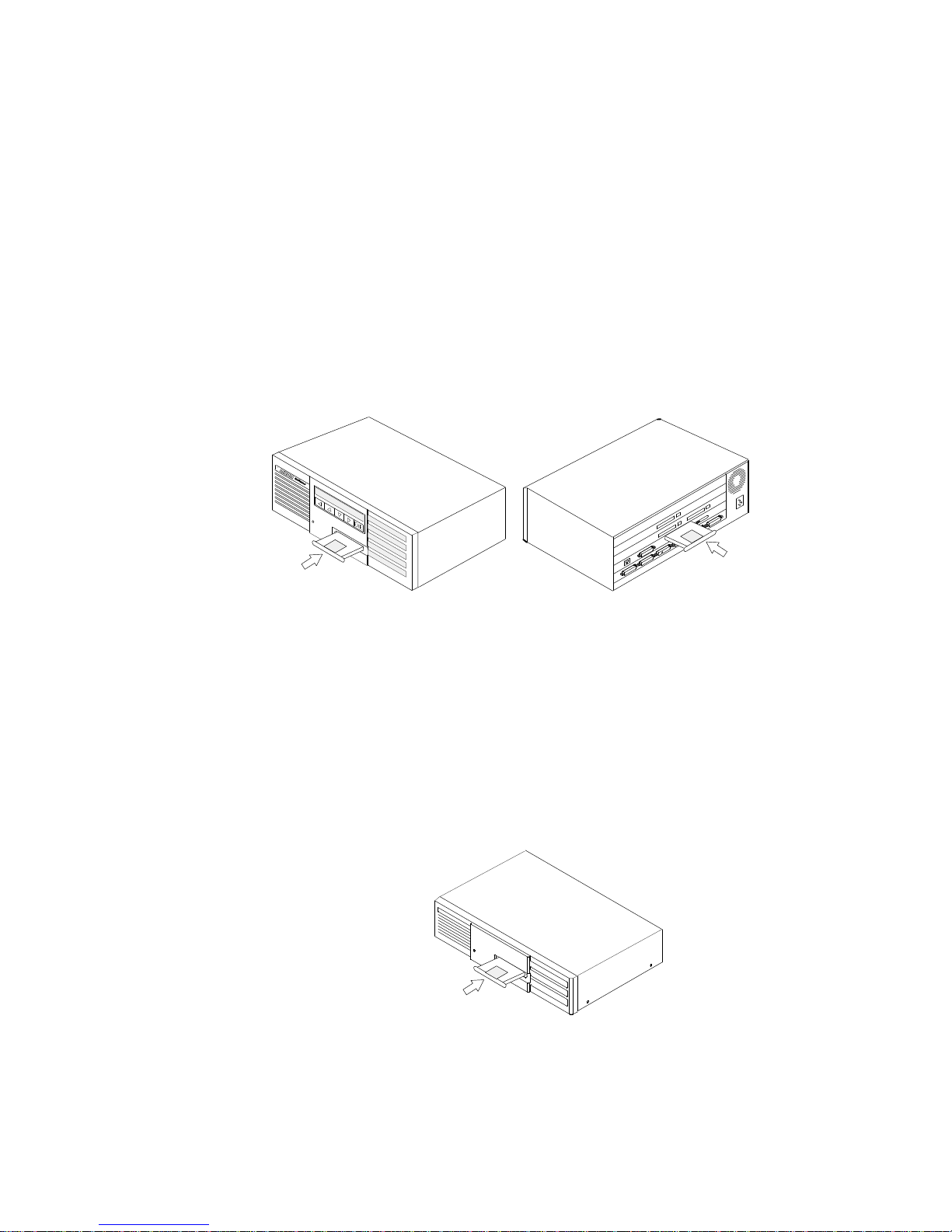
Overall NetRunner operation and configuration is controlled by the
NetRunner FlashPak or FEATUREPAK cartridge, which resides in the
Communications Control Module (CCM). This cartridge is installed in the
front of the unit.
LAN operation and configuration is controlled by the NetRunner Integration
Router FlashPak cartridge, which is installed in the Local Area Network
(LAN) module at the rear of the unit.
NetRunner
Integration Router
FlashPak Cartridge
NetRunner
CCM FEATUREP
AK or
FlashPak Cartridge
NetRunner
Model 75E
For the NetRunner 75E, overall NetRunner operation and configuration is
controlled by a Flash bank installed on the LAN/WAN module. (The standard
model contains singlebank Flash; a dualbank Flash is an option.) The LAN
operation and configuration is controlled by the Integration Router cartridge
which is installed in the front of the unit.
NetRunner
75E
Integration Router FlashPak Cartridge
Page 15

NetRunner W
AN User’
s Manual
Introduction
1-6
Compatibility
Compatibility Across the
Wide Area Network
(WAN) link
Releases 2.5 and above of the NetRunner system (Communications Control
Module) software are compatible with the current CCM software release.
The Integration Router is WAN compatible with release 3.0 or later of the
NetRunner LAN module software. To operate properly, the LAN modules of
all Integration units, which communicate across a single WAN to the
Integration Router, must be running LAN Module software release 3.0 or
later.
Compatibility On the
LAN Segment
The Integration Router is compatible with all standard bridges, routers,
bridge/routers, and other devices that reside on the same Ethernet segment
as the Integration Router. The Integration Router is compatible with all
previous releases of NetRunner across the Ethernet segment, as well.
Compatibility in
Mixed Networks
In a LAN network containing mixed NetRunner system software releases,
the LAN module with the oldest/least performance module will govern the
overall performance and feature set of the Integration Router.
System Compatibility
For optimum Integration Router performance, MICOM recommends using
release 3.2 revision C or later system (Communications Control Module)
FEATUREPAK or FlashPak cartridge.
The network LAN code download feature of Integration Router release 6.0
requires that the NetRunner contain release 4.2 revision B or later system
(Communications Control Module) software. NetRunner units containing
earlier releases of cartridges do not support this feature.
Page 16

NetRunner WAN User’
s Manual
Introduction
1-7
Manual Companions
In addition to this manual, you received other manuals to facilitate the setup,
startup, and use of your NetRunner products. In most cases, this is the order
in which you use the manuals.
D The 3Slot Chassis or 5Slot Chassis Installation and Cabling manuals
provide instructions on setting up the unit, turning it on, cabling the
unit, and disassembling and reassembling the unit.
D This NetRunner WAN User's Manual is written to help you address
the features and configurations of the Wide Area Network (WAN)
functionality of the basic NetRunner unit. In this manual, the logical
progression dictates that certain portions of menus are accessed at
different times. Please note that, for each function explained, only the
applicable menu portions are discussed; for an explanation of the full
menu, please refer to the optional Command Facility Reference Guide.
D The Integration Router manual provides information about the Local
Area Network (LAN) functionality, along with a complete description
of the LAN commands.
D The Code Download User's Manual explains the procedures to
download software.
D The LCD/Keypad manual details the use of the Liquid Crystal Display
(LCD) and the keypad, which is a standard feature on the front of
most NetRunner models.
Optional System Manual
The Command Facility Reference Guide, available in the optional System
Manual (Model NR/UM/5), focuses in detail on all menus of the Command
Facility (including optional modules). This guide will be especially handy
when configuring the NetRunner unit for the first time, because it more
completely discusses the menus, and each of the options and/or procedures to
get to the next menu, or to complete the required function.
The Menu Flow Diagram, also part of the System Manual, shows the
Command Facility and LCD/Keypad menus and hierarchy.
The optional System Manual also consists of manuals for a voice module and
ISU module. All other optional modules are delivered with manuals which
pertain to their individual installation and configuration requirements.
Page 17

NetRunner WAN User’
s Manual
Introduction
1-8
Terminology
D WAN link refers to the MICOM WAN network link. In the NetRunner
Command Facility menus, the WAN link is called the interconnect
link.
D Integration Router refers to the combination of a LAN module with an
EasyRouter FEATUREPAK or FlashPak cartridge (release 5.0 or
later) installed.
D LAN module is the circuit board with Ethernet connectors that is
installed in a unit. It does not have the functionality of an Integration
Router until the appropriate FEATUREPAK or FlashPak cartridge is
installed. For NetRunner 75E, the components that make up the LAN
module for other NetRunner units are part of the 75E's LAN/WAN
module.
D Bridge refers to two or more LAN modules (or Integration Routers in
bridge mode) and the WAN link(s) between them.
D A node is a NetRunner unit.
D A unit is any MICOM Integration unit.
D A cluster is a group of nodes assigned the same cluster name.
D A device is any kind of network equipment (personal computers,
servers, printers, and so forth).
D A module is commonly referred to as a card or board.
Symbols
<cr> Any terminal key (such as RETURN or Enter) that generates a car
riage return.
<break> Any terminal key that generates a BREAK signal.
^ Any terminal key (such as Ctrl) that sets the terminal to shift to the
Control character mode.
<esc> Any terminal key (such as Esc) that generates an escape character.
Represents an option number selected using the terminal keyboard.
It is shown in menu progressions beside the desired option name. The
option number itself is shown except when it varies among models.
# Symbol meaning number.
Page 18

NetRunner WAN User’
s Manual
Introduction
1-9
Basic Operation
Bridges and routers operate transparently to LAN users, including the
NetRunner equipment operators at either side of the WAN network link.
Following poweron and learning phases, data packets pass between LANs in
either direction. Normally, the NetRunner operator may monitor the LAN
traffic from time to time by observing the action of the indicator lights
described in Section 7, but will otherwise not need to be involved in the
operation.
With the exception of a malfunction, operator intervention will be required
only to reconfigure the NetRunner or to obtain a display of existing
parameters. These actions can be performed from a LAN device like a
terminal or PC, or from the command console at any NetRunner unit.
The NetRunner units isolate network traffic, effectively controlling (filtering)
the amount of traffic traveling between segments (across the WAN network
link), which reduces overall network traffic. The Integration Router
automatically discovers the other bridges and routers during the learning
phase of the NetRunner startup sequence.
When bridging or in EasyRouter mode, the Integration Router operates at the
Data Link layer of the OSI reference model. This means that the Integration
Router does not reproduce physical layer network problems like collision or
network faults. While bridging, the Integration Router is not protocol
sensitive. Data packets travel from the source to the destination node
without the Integration Router needing to interpret the data.
When configured for traditional routing, the Integration Router operates at
the Network layer of the OSI reference model. The Integration Router can
route IP and IPX packets. All other packet types are bridged.
Page 19

NetRunner WAN User’
s Manual
Introduction
1-10
Options
Module Description
Voice/Fax Module These modules offer the ability to send voice or
fax communications digitally across the link and
are available to meet the requirements of most
countries.
The Digital Direct Series of modules provide a
high-speed digital interface to a PBX and wide
area network (WAN). It is designed for the
NetRunner 500ET, 2000E and 2000ED. Up to 24
channels are supported.
CEM (Channel Expansion
Module
)
12-Channel CEMs:
D A 12-channel async CEM with 8-pin
connectors which are RS-232 (V.24)
compatible.
D A 12-channel async CEM with 8-pin
connectors and integral line drivers which
are RS-422/423 compatible.
6-Channel CEMs:
D A 6-channel sync/async CEM with female
DB-25 connectors which are RS-232 (V.24)
compatible.
D A 6-channel sync/async CEM with DMA.
This module will support additional
interconnect links. Connectors are female
DB-25, RS-232 compatible. Only for
NetRunner 1000E and 2000E,ED.
D A 6-channel async CEM with female DB-25
connectors which are RS-232 (V.24)
compatible.
ISU Module The Integrated Service Unit (ISU) combines a
Channel Service Unit (CSU) and a Data Service
Unit (DSU) to connect to the Digital Data System
(DDS) network. This provides a synchronous line
at a speed of 56,000 bps. This module is
available as a single or dual channel ISU. The
dual channel ISU is available for models
NR2000E, NR2000ED, NR1000E, and NR500ET.
NMS Module The NMS module provides two ports: the
dedicated command port for access to the
Command Facility, and the log port for hard-copy
output of reports. An external alarm device can
be connected for audible or visual alarm
notification. (For NetRunner 2000E, 2000ED, and
500ET, module must be Rev. D or later.) This
module is not offered for the NetRunner 75E.
Page 20

NetRunner WAN User’
s Manual
Introduction
1-11
Additional Options Description
NETMan The MICOM Network Management System oper-
ates on a PC and is available in three packages:
D Managing up to 10 nodes.
D Managing up to 30 nodes.
D Managing up to 254 networks of up to 254
nodes each.
Power Plus Redundant Power
Supply Kit
A kit offering dual (redundant) power supplies for
models except the NR75E.
STADIA Integration Hub A hardware enclosure comprising three power
supplies which can support up to four NetRunner
CCMs plus optional modules and one NMS module.
Rack-Mount Kit There are three rack-mount kits:
D For all NetRunner models except model
NR75E with standard power supply.
D For all NetRunner models except model
NR75E with Power Plus.
D For NetRunner 75E (3-slot chassis).
Converter The following converters are available:
D The V.35 Converter can be attached to any
port operating at a speed of 38.4 Kbps or
greater and interfaces a link to a DTE/DCE.
D The RS-530 converts RS-232 (V.24) ports to
RS-530, which work in conjunction with
RS-422 and CCITT V.11 circuits. RS-530 provides higher data rates and longer distances
from the same DB-25 connector the RS-232
(V.24) uses.
D The X.21 Converter adapts RS-232 (V.24)
ports to X.21 (V.11).
SNAPS The MICOM SNA Protocol Spoofer (SNAPS) is an
intelligent device designed to provide SDLC support. It provides local polling for IBM SNA applications for either the host (FEP) or controller (PU),
using the network to channel the SNA traffic.
Page 21

NetRunner WAN User’
s Manual
Introduction
1-12
Module Locations
5-Slot Chassis
There are five chassis positions available for modules in the NetRunner
(except in the NetRunner 75E). These are identified from bottom to top as
module locations A through E. The Communications Control Module (CCM)
is always in module location A. The LAN module may be installed in any
module location BE. It is normally installed in module location B.
3-Slot Chassis
There are three chassis positions available for modules in the NetRunner
75E. These are identified from bottom to top as module locations A, B, C.
The NetRunner 75E contains a LAN/WAN module in location A. This module
contains both the Local Area Network software and the Wide Area Network
software. The LAN portion of the LAN/WAN module is mapped logically to
module location E.
Populating the NetRunner
(Module Possibilities and Quantities)
The following lists the modules available for the NetRunner products, the
module locations where each can be installed, and the maximum number of
modules which can be supported without consideration to limits imposed by
the hardware or software.
NetRunner 2000ED Network Node, dual LAN modules (Model NR2000ED)
Module Locations
Modul
e
A B C D E
Maxi
mum Modules
Supported By Unit
CCM X 1
Data Expansion Module
6-channel DMA
1
X X X 1
LAN Module X X X X 2
Voice/Fax
single-channel
dual-channel
XXXXXXX
X
2
2
ISU
single-channel
dual-channel
XXXXXXX
X
1
1
Modem
14.4
X X X X 2
1
Supports six additional links when switch setting on module is set for B. With any other switch
setting, the module supports 6 async or sync channels.
Page 22

NetRunner WAN User’
s Manual
Introduction
1-13
NetRunner 2000E (Model NR2000E) and 1000E (Model NR1000E) Network Nodes
Module Locations
Modul
e
A B C D E
Maxi
mum Modules
Supported By Unit
CCM X 1
Data Expansion Module
6-channel DMA
1
X
X X 1
LAN Module X X X X 1
Voice/Fax
single-channel
dual-channel
XXXXXXX
X
3
3
ISU
single-channel
dual-channel
XXXXXXX
X
1
1
Modem
14.4
X X X X 2
1
Supports six additional links.
NetRunner 500ET Network Node (Model NR500ET)
Module Locations
Modul
e
A B C D E
Maxi
mum Modules
Supported By Unit
CCM X 1
LAN Module X X X X 1
Voice/Fax
single-channel
dual-channel
XXXXXXX
X
3
3
ISU
signal-channel
dual-channel
XXXXXXX
X
1
1
Modem
14.4
X X X X 2
NetRunner 75E Branch Office Router (Model NR75E)
Module
Module
Locations
Maximum Modules
A B C
Supported By Unit
LAN/WAN Module X 1
Voice/Fax
single-channel
dual-channel
XXX
X
2
2
ISU
single-channel
X X 1
Modem
14.4
X X 1
Page 23
NetRunner WAN User’
s Manual
Introduction
1-14
Hardware Conventions
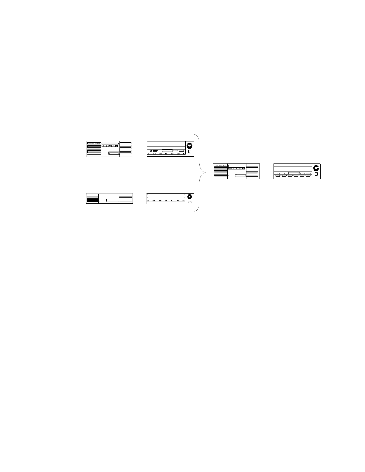
There are slight variations in the appearance of the NetRunner models. Due
to these variations, the following convention will be used in this manual to
represent all the NetRunner models. If information specific to a particular
model is required, the detail for that model will be shown.
Front Back
NR2000ED
NR2000E
NR1000E
NR500ET
NR75E
Front Back
NetRunner
M
odels
Use
r M
anual Convention
Page 24

2-1
Network Planning 2
This section provides information in preparation for organizing and
configuring your network. Planning involves the following topics:
D Planning the Topology
D Planning Prerequisites
D Clusters
D Plan the node numbers and node IDs (names) for the NetRunner
nodes
D Channel prioritization across the Wide Area Network (WAN) link
Network Topologies
In the following pages, several topologies are discussed. Due to the flexibility
of the unit, one or all of the following topologies are supported by your
network:
NetRunner Model
Topology 75E
500ET 1000E 2000E,ED
Point-to-Point X X X X
String X
1
XX X
Star, Distributed Star X
1
XX X
Mesh, Delta, Ring: looped
networks
(i.e., closed loops)
X
1
XX X
1
Frame relay applications only.
MICOM recommends that you work with your MICOM Certified Distributor
to ensure that the NetRunner unit meets the requirements of your network
in the most effective and costefficient manner.
Page 25
NetRunner WAN User’
s Manual
Network Planning
2-2
Terminated or Switched
Utilizing these topologies, a NetRunner 500ET, 1000E, and 2000E,ED can
serve as either a terminated node (traffic is terminated in, or attached to the
local node) or a switching hub (no locally attached devices). The NetRunner
75E is designed as a feeder to a switched hub. Without local traffic
(data/voice/LAN), the NetRunner's WAN link capacity increases. The
following elements need to be considered when putting together a network:
NetRunner Model
75E 500ET 1000E 2000E,ED
D Link Capacity
(non-frame
relay)
Terminated 64 Kbps 148 Kbps 128 Kbps 256 Kbps
Switched n/a 148 Kbps 192 Kbps 384 Kbps
D Delay (varies be-
tween channel
type and protocol)
Due to delays, do not exceed six link hops in any network path for units with voice/fax modules. Limit the
link hops to three (four nodes total) if you are configuring
dynamic rate adaption
on your voice/fax module.
Note: Frame relay can be clocked to T1. A V.35 interface is required for
these higher rates.
2
3
4
5
1
6
Example of a 6-Node Hop
Page 26
NetRunner WAN User’
s Manual
Network Planning
2-3
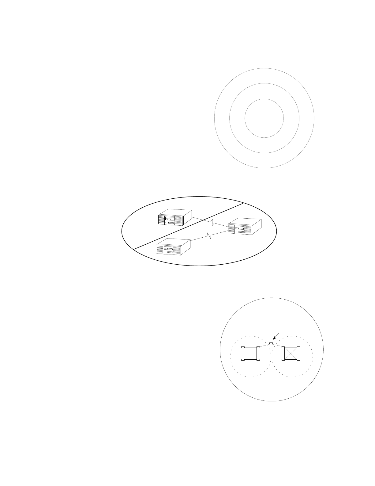
Placement in the Network
Release 4.1
an
d L
ater
Mes
h C
onfigured
Releas
e 4.0 and 4
.1
Non-Mesh
Releas
e 3.2 and E
arlier
D Release
4.1 and later Mesh: configure for mesh
in the hub of the network. Configure mesh for
,
–
Units with closed loops
–
Connecting units between looped networks
D
Release 4.0 and later Non-Mesh: attach to like
kinds (same type).
D
Generally keep
like types
together
. Do not
partition (separate) units with earlier revisions.
Note:
Exception – A NetRunner 75E Release 4.0
and later may be attached to an end point of
a Release 3.2 network.
Mesh
Non-Mesh
Mesh
Note: Do not partition (separate) mesh units with non-mesh units.
Mesh
must be on
Network
A
Network
B
The example shows two mesh networks (A and B)
connected by a single unit. In order for the two
networks to communicate, the
connecting node(s)
must have mesh configured on (refer to page 3-9).
Page 27
NetRunner W
AN User’
s Manual
Network Planning
2-4
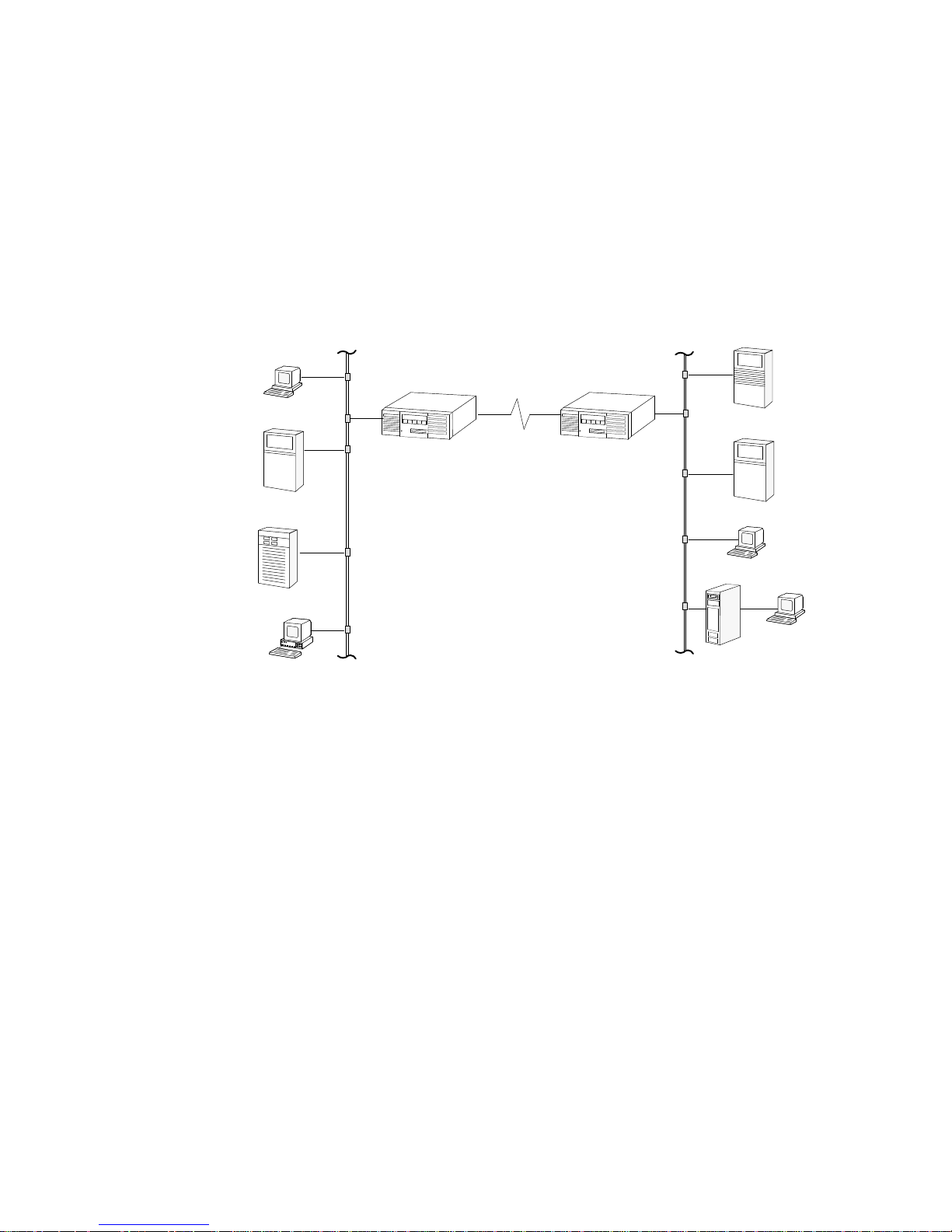
Point-to-Point
The most basic of topologies is the pointtopoint: point A to point B. The
NetRunners can operate in a pointtopoint switching topology over
terrestrial, satellite, and microwave services.
In a pointtopoint application, a link is formed between two Integration
Routers across a WAN network. Packets are forwarded between the two
nodes. Filters may be set for specifying which types of packets each
EasyRouter accepts or ignores.
TCP/IP Host
Fil
e S
erver
Terminal
DEC Host
Terminal
NetWar
e S
erver
PC
TCP/IP Host
Point-to-Point Operation
Page 28
NetRunner WAN User’
s Manual
Network Planning
2-5
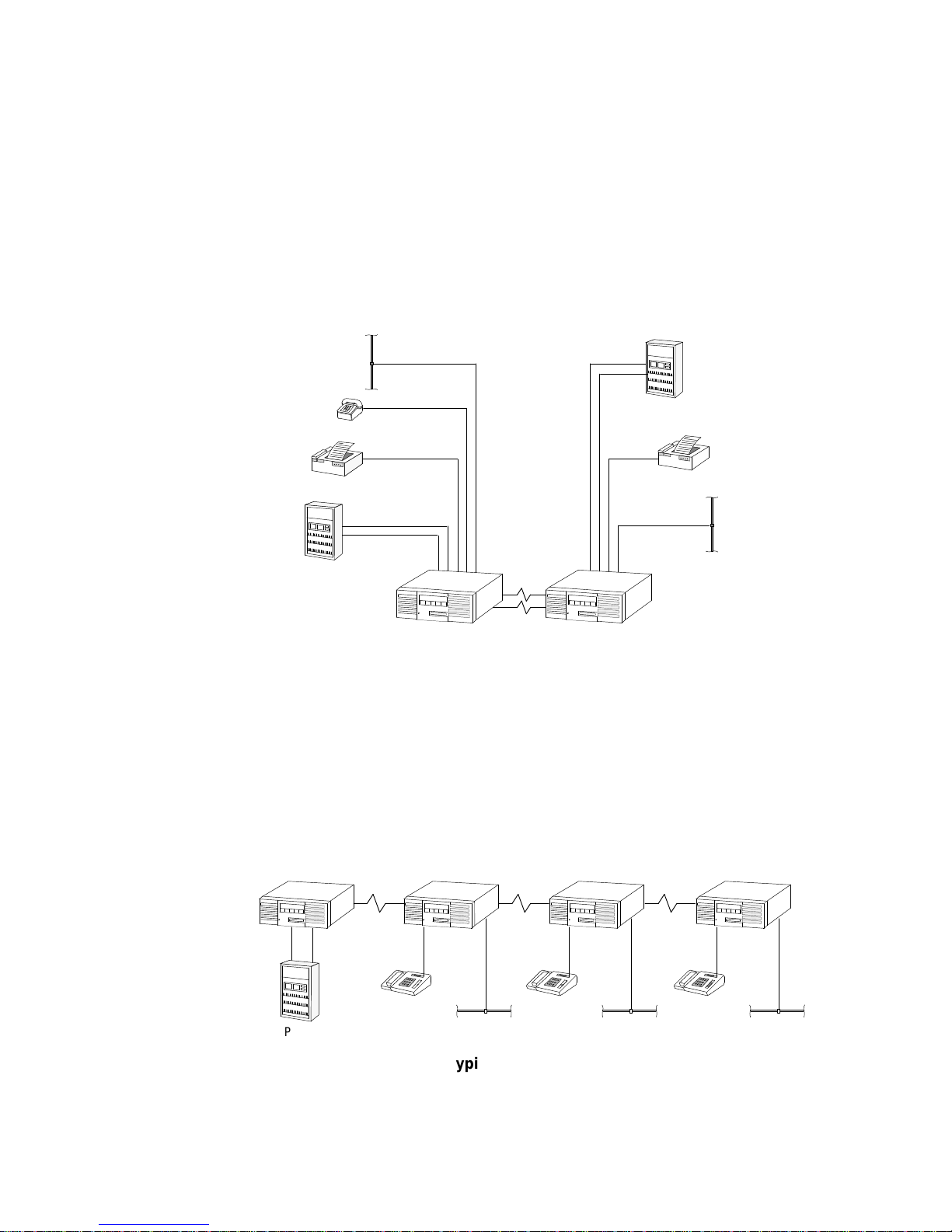
Dual Composite Link Load Balancing (with Redundancy) Application
(for all NetRunner models except the NR75E model)
All WAN network link traffic between NetRunner nodes is load balanced
between Link A and Link B. In the event of a single link failure, all traffic is
automatically rerouted over the remaining link. Note that in this application
with NetRunner 2000E units, dual 128 Kbps links are possible; however this
link speed may limit the number or type of devices that can be attached due
to processor constraints.
PBX
Fax
PBX
Fax
Node
A
Nod
e B
Link B
Link A
NetRunner
2000E
NetRunner
2000E
Phone
Link Load Balancing
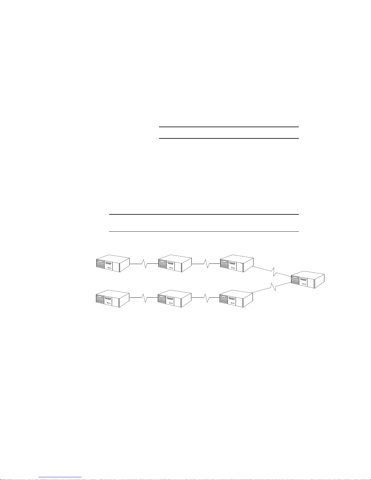
String
If several NetRunner units are linked together, a string topology is created.
There is a maximum of six nodetonode hops allowed for units with voice/fax
modules.
Any or all of these may be NetRunner 500ET, 1000E or 2000E network node
units. NetRunner 75E
1
can be at the ends of the string only.
PBX
NetRunner NetRunner NetRunner NetRunner
Typical String Network
__________
1
The exception to this is frame relay links.
Page 29
NetRunner WAN User’
s Manual
Network Planning
2-6
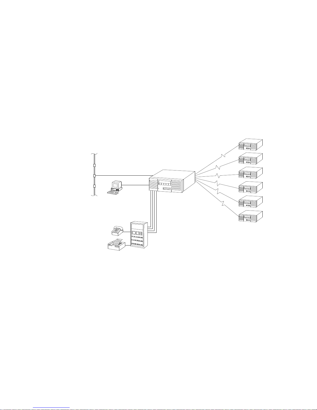
Star
The star topology is a network with a single major center connected to access
points.
In a unit with the NetRunner 2000E or 1000E, the points of the star can all
be NetRunner units. The NetRunner 2000E or 1000E can act as the network
hub for up to 12 other NetRunner units. (The 5000E/6DMA Module must be
installed in module location B to obtain the six additional links.) Each
remote site NetRunner can support additional links to other NetRunner
units.
In a star topology where a NetRunner 500ET is the central node, three links
may connect to other NetRunner units.
PBX
Fax
NETMan
Typical Star Application
Page 30
NetRunner WAN User’
s Manual
Network Planning
2-7
Multi-site
The NetRunner Release 3.0 and later, supports multisite operation. Rather
than a simple connection between only two NetRunners, and subsequently an
interconnection between only two LANs, multisite operation supports
distributed LAN topologies, allowing interconnection between multiple
NetRunners (see the example shown in the figure below). In addition,
Integration Routers and NetRunner LAN interfaces may be grouped into
clusters of up to 12, and clusters connected over a common LAN (refer to
Clusters on page 212) so that both small and large wide area networks are
supported.
Refer to the Integration Router manual for more multisite application
information, such as Filtering and The Spanning Tree.
Multi-site Operation
Page 31

NetRunner WAN User’
s Manual
Network Planning
2-8
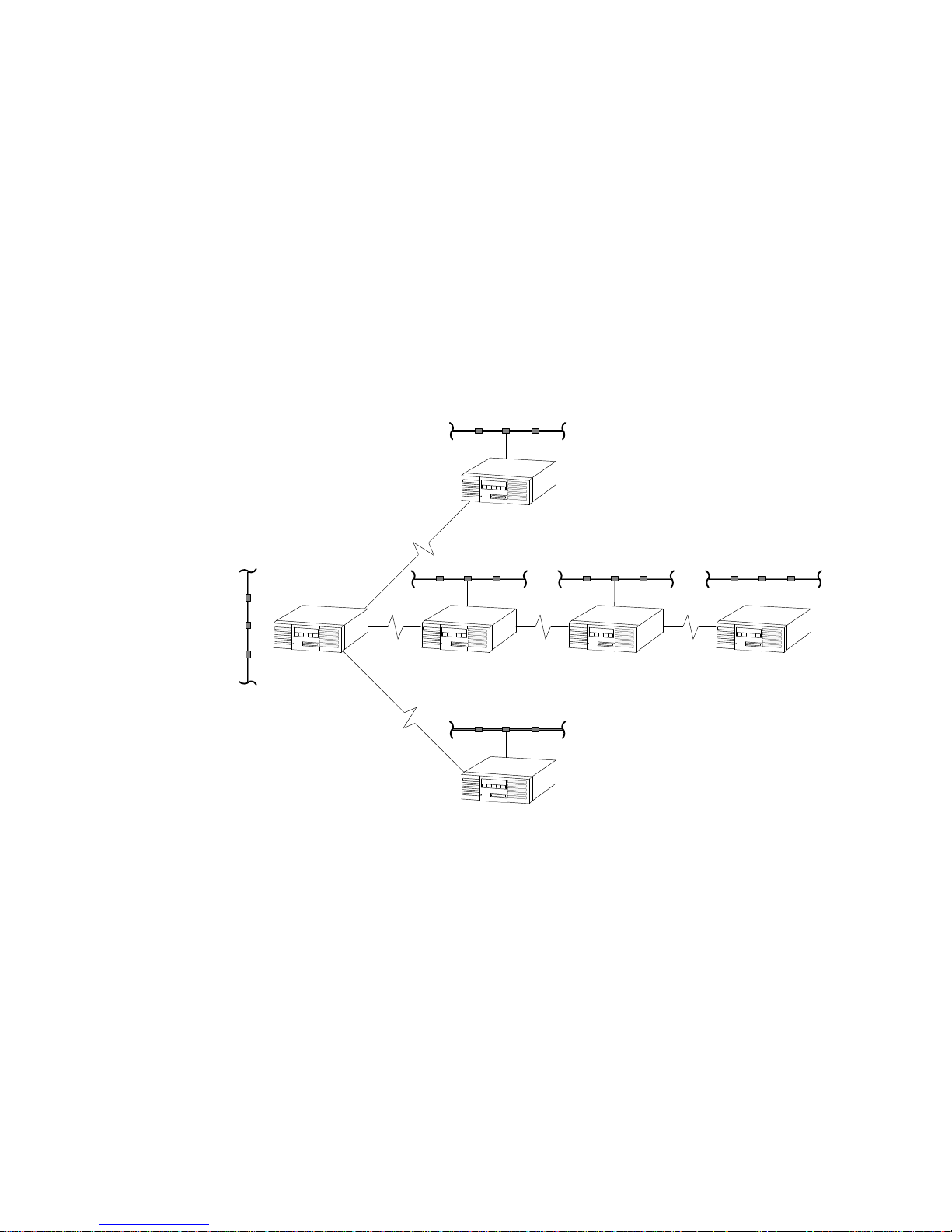
Distributed Star
If two or more star networks are connected, the topology can be described as
a distributed star.
Clusters
A and B a
re
interconnecte
d h
ere
Clusters A an
d B a
re
not
i
nterconnecte
d h
ere
Cluster A Cluster B
Page 32

NetRunner W
AN User’
s Manual
Network Planning
2-9
Delta, Ring and Full-Mesh
These topologies are common in that there are closed loops. As such, there is
more than one path (link) available which offers network resiliancy in the
event of a link failure. The NetRunner 500ET, 1000E, 2000E and 2000ED
Network Nodes are capable of working within these topologies. The
NetRunner 75E model can be used as feeders into these networks. The Delta
is the most basic of the meshtype topologies; the FullMesh is the most
complex. In creating networks with a closed loop or the fullmesh, it is
always important to remember the cost and delay factor and use only the
minimum links necessary to assure redundancy.
Full-Mesh
Delta
Ring
Delta, Ring and Full-Mesh Applications
Page 33

NetRunner WAN User’
s Manual
Network Planning
2-10
Frame Relay
Public frame relay service offers you the benefits of leased line connectivity to
multiple sites. In specific regions, frame relay is more economical than
leased lines. This is because frame relay provides multiple permanent
virtual circuits (PVCs) or data link connections (DLCs) within the same
physical access line. This reduces to a single access line the multiple leased
lines required to provide anytoany communications among several locations.
One physical connection into the public frame relay network logically
provides the connectivity of a mesh network, although physically the network
is a star topology.
Frame
Relay Link
PVC
Frame Relay Connectivity
Applications predominantly use frame relay services for local area
networking (LAN) and/or Systems Network Architecture (SNA)
internetworking.
Page 34

NetRunner WAN User’
s Manual
Network Planning
2-11
Planning Prerequisites
In addition to the topics about planning your network, you should consider
the following:
D Do you need to cluster your nodes?
How many nodes are interconnected in your network? A network of
up to 254 nodes can be designed. For networks consisting of more
than 12 nodes, you will need to group nodes together in clusters. For
networks with 12 or less nodes, clustering is optional. More
information on clusters is explained on the next paragraph titled
Clusters.
D Note the LAN module's hardware address.
The LAN module's hardware address is written on a label on the back
panel of the LAN module. You may record this in the worksheets
appendix, page A1. For the NetRunner 75E, the hardware address is
written on a label on the back panel of the LAN/WAN module.
D Traditional IP routing considerations
(Refer to the Integration Router manual, which contains more
information on these prerequisites):
- Network addressing and subnetting. Acquire the necessary IP
addresses from the Internet Authority.
- Node addressing. You must assign unique IP addresses to all the
nodes on your network.
- Default gateways. There must be a default gateway (router)
established.
- Domain Name Servers (DNS). Host tables that must be updated
to reflect the new network architecture established by routing.
- Bootp. Any machine that requires Bootp during startup must
either be on the same LAN segment as the Bootp host, or the
Bootp host must be able to download Bootp through the
Integration Router.
D Traditional IPX routing considerations
(Refer to the Integration Router manual which contains more
information on these prerequisites):
- Unique network numbers for each LAN segment. (In bridged IPX
networks, all LAN segments have the same network number.)
- All servers on a network segment must have unique network
numbers, and these numbers must not be the same as any LAN
segment network number.
- The WAN for all nodes in one cluster is considered as one virtual
LAN segment. Thus, only one network number is required for the
WAN.
Page 35

NetRunner WAN User’
s Manual
Network Planning
2-12
D What type of connection will be made to the LAN?
For unshielded, twisted pair LANs, you can use the UTP port (8pin
modular jack). The NetRunner is then connected to a port on a
twisted pair hub. For other LANs, you must use the AUI port along
with an appropriate transceiver and transceiver cable.
The connections are described in the Integration Router manual. The
connections for the NetRunner 75E are described in the 3Slot Chassis
Installation and Cabling Manual.
D Will you be using a frame relay link? The following information is
needed from the carrier provider:
- DLCI numbers and parameters
- Network address
- Local management protocol (Annex D, LMI Rev. 1, or none)
Local management parameters (for the protocol)
- Type of interface required
(More information is provided on Frame Relay Links in Section 3).
Clusters
The NetRunner allows a network to be partitioned into groups called clusters.
A cluster is formed when two or more NetRunners are grouped together in
the network and given the same cluster name. A single cluster may contain
up to 12 interconnected NetRunners on a WAN. Configuring multiple
clusters allows you to create a WAN exceeding 12 nodes, up to a maximum of
254 NetRunner units per WAN.
All NetRunners are shipped with the same cluster name <none>. The cluster
name is userconfigured.
Clustering, as mentioned here, allows you to efficiently expand your network.
A cluster segments the network to improve performance and maximize
bandwidth for LAN traffic. This is especially true in larger networks
consisting of more than 12 NetRunners. It also secures portions of a network
by allowing communication only between NetRunners with the same cluster
name.
Clusters can only be interconnected over a LAN.
Page 36

NetRunner WAN User’
s Manual
Network Planning
2-13
Clusters A an
d B a
re
interconnecte
d over the E
ther-
ne
t LAN h
ere
Clusters A an
d B a
re
not
i
nterconnecte
d h
ere
Cluster A Cluster B
Local Cluster Interconnection
D Each NetRunner may belong to only one cluster. (NetRunner models
containing two LAN modules count as two nodes. The two LAN
modules can be assigned to one cluster and count as two nodes in that
cluster, or they can each be assigned to different clusters - and count
as one node in each cluster.)
D A new NetRunner will only attempt connection via the WAN with
other NetRunners assigned to the default cluster name of None. To
connect a new NetRunner to a different cluster, its cluster name needs
to be changed. This procedure is described in the Integration Router
manual.
D Each cluster may consist of up to 12 interconnected NetRunners. For
example, if you connect a new NetRunner to a WAN with 12 nodes
already in place, a request for connection by the new NetRunner will
be ignored, as each node's address table already holds the maximum of
11 other node addresses.
To add the new node to the network, the original 12 nodes need to be
partitioned into smaller clusters and the new NetRunner assigned to
one cluster or another. This is illustrated in the following figures.
Page 37

NetRunner WAN User’
s Manual
Network Planning
2-14
Cluster None
Cluster Alpha Cluster Delta Cluster Omega
13th Node
13th Node
Connecting a 13th NetRunner Node to Existing Clusters
Page 38

NetRunner WAN User’
s Manual
Network Planning
2-15
Communicating Between Clusters
Clusters increase network efficiency by separating LAN traffic from voice/fax
and data traffic.
As an example, refer to the figure below. Though the two clusters shown are
connected through a 56 Kbps WAN network link (point A), the link only
carries voice/fax and data traffic. LAN traffic between the clusters passes
through the common LAN at point B. Once inside a particular cluster, LAN
traffic is then forwarded over the WAN links of the particular cluster.
Connecting clusters in this manner increases overall network performance
and adds additional network security, as nodes in a particular cluster may be
set to forward or accept only certain packet types (filtering).
Cluster
B
Cluster A
Poin
t B
(bridg
e t
raffic)
Poin
t A
(voice/fax
, data t
raffic)
5
6 K
bps
Cluster-to-Cluster Communication
Planning the NetRunner Node Numbers and Node IDs
Each NetRunner is referred to as a node. All nodes connected locally are
considered local.
All nodes on the other side of a WAN network link are considered remote.
Each node must have its own node number and node ID, and there can be no
duplicates in the network. (Sometimes node IDs are referred to as node
names.)
The node assigned the lowest node number and which contains a Real Time
Clock (RTC) device is the network time master. It broadcasts time, day and
date to the other nodes in the network.
The LAN node ID is automatically assigned by the LAN interfaces while they
are communicating to each other.
Page 39

NetRunner WAN User’
s Manual
Network Planning
2-16
Syntax
WAN network links are called interconnect links in the software.
NODE # Use 1 through 254.
NODE ID One to eight uppercase or lowercase characters. The first
character must be an alpha character. The remaining
characters can be any combination of alphanumeric characters
and the underbar (_). Spaces can not be used. Node IDs are
not case sensitive. It is recommended that they be kept short.
Channel Prioritization on Interconnect Links
By default, integral voice/fax channels have priority for transmission across
the interconnect (WAN network) link followed by sync, and then LAN and
async data. This priority scheme minimizes delay for voice/fax and sync
connections. There are occasions when a sync channel may need to have
bandwidth priority over voice/fax. To accomplish this, it is necessary to
configure the sync channel (both local and remote ports) for high priority
(option number varies depending on protocol, refer to page 57 and Table C7
on page C12), and the voice/fax channel for low priority (refer to the voice/fax
manual). For sync and voice/fax channels to have equal priority, set them
both for high priority.
Note: A sync channel(s) configured as TDM protocol has reserved bandwidth which is
not shared. The priority function noted above does not apply to channel(s)
configured for TDM.
Page 40

3-1
Startup 3
At this point, the following should be completed:
D LAN cables should be installed (refer to the Integration Router
manual)
D NetRunner FlashPak or FEATUREPAK cartridges should be installed
and the unit powered up per the Installation and Cabling manual.
This section introduces the Command Mode and Command Facility and
configuring a local node number and node ID (name) for the NetRunner node.
This configuration is required and prevents duplication of the node IDs in the
node network.
The Command Mode is a single menu which supports configuration and
testing of the local port and access to the Command Facility.
The Command Facility contains the parameters that control the features and
functions for the NetRunner. In the Command Facility, parameters remain
at their most recently set values. The optional Command Facility Reference
Guide documents each menu and option within the Command Mode and
Command Facility.
Note: The NetRunner Command Facility menus do not contain the commands for
configuring the LAN. Rather, they provide a means to access the LAN’s own
command line interface from the Command Facility.
Refer to the Integration Router manual for the LAN procedures and commands.
Page 41

NetRunner WAN User’
s Manual
Startup
3-2
Command Mode
Connect an ASCII terminal, or a PC with terminal emulation software, to any
asynchronous channel in the unit. This terminal will provide access to the
NetRunner Command Mode and Command Facility until you define a server
name and address. After these have been defined, you can access the
NetRunner from the LAN.
Entering the Command Mode
The Command Mode is accessible from any of the async ports local to that
CCM.
First Time
Access to the
Command Mode:
Set the terminal to the settings shown below.
Async Terminal Settings
Data Rate 9600
Code Level 8 bits per character
Stop Bits
1
Parity None
Operation Full-Duplex
After the initial connection to the Command Mode, the
terminal parameters (except Operation) may be reconfi
gured. Once the new parameters are selected, exit the
Command Mode by entering
<break>. The new parame
ters will now be in effect. Set the terminal to the new
parameters and reenter the Command Mode, if desired.
Page 42

NetRunner WAN User’
s Manual
Startup
3-3
To Enter
Press ^X
Command Mode then <break>
The Command Mode Menu is displayed.
1996 MICOM COMMUNICATIONS CORP.
ALL RIGHTS RESERVED
UNPUBLISHED - RIGHTS RESERVED UNDER THE
COPYRIGHT LAWS OF THE UNITED STATES.
COMMAND MODE: CHANNEL
1. ASYNC CHANNEL LOOPBACK
2. LOCAL CHANNEL CONFIGURATION
3. COMMAND FACILITY MAIN MENU
4. EXIT
The Command Mode offers four options:
D Async Channel Loopback: Contains a selection of loopback
tests.
D Local Channel Configuration: Provides control and modification of
the local port only.
D Command Facility Main Menu: Provides access to the local unit's
Command Facility.
ENTER PASSWORD: <cr>
D
Exit: Disconnects the terminal from the
Command Mode.
To Exit
Command Mode
Either
D select option 4, Exit, or
D press <break>.
The
COMMAND
MODE DISCONNECT
message is displayed.
Page 43

NetRunner WAN User’
s Manual
Startup
3-4
Local Channel Configuration
Intended for changing parameters on the port to which you are attached, use
the following path to access the menu.
COMMAND MODE:
LOCAL CHANNEL CONFIGURATION
2
Option Default Description
1. Data Rate 9600 Data rate in bps (bits per second).
2. Code Level 8 Number of data bits per character.
3. Parity None Depending on code level chosen, one of two
menus will appear.
4.
Stop Bits
1 Number of stop bits inserted at the end of a
data character.
5. Echo Off Turns the echo function on or off.
6. CR Delay
1
0 Carriage return delay.
7. LF Delay
1
0 Line feed delay.
8. FF Delay
1
0 Form feed delay.
Note: To ascertain the correct configuration values, consult the user manual of the
device connected to the port.
For ports connected via dialup modems, parameters remain in effect only
for the duration of the call.
For directly connected ports, the parameter changes remain in effect until
changed in this menu or in the Channel Characteristics (of the Async
Channel) Menu.
Important
Be sure your terminal is reconfigured to match the new
local channel configuration.
__________
1
Delay values are configured in number of characters (099) to account for required mechanical actions of the
equipment attached to the port.
Page 44

NetRunner WAN User’
s Manual
Startup
3-5
Command Facility
The Command Facility is intended for use by the system administrator. It
contains the configuration, diagnostic and system administration options for
all ports of the unit. Only one port may access the Command Facility at a
time.
Note: The terminal accessing the Command Facility Main Menu must have the Com-
mand Facility Main Menu Access function enabled (factory default).
The default Globa
l p
asswor
d i
s
n
o p
assword, s
o p
ress <cr>.
Press <cr>
ENTER CLASS: $CMD
ENTER CLASS PASSWORD: <cr>
At the prompt
1
, enter $CMD.
Access via $CMD Access via ^X <break>
Press ^X
then <break>
COMMAND MODE:
3 COMMAND FACILITY MAIN MENU
COMMAND FACILITY MAIN MENU [!240]
1. VIEW CONFIGURATION
2. STATUS/STATISTICS
3. CONFIGURE LOCAL NODES
4. CONFIGURE/VIEW REMOTE NODE
.
.
.
EXIT COMMAND FACILITY
To Enter
Command Facility
Either
Exit option varies
dependin
g o
n model.
To Exit
Command Facility
Either,
D select the Exit option
or
D press <break>.
__________
1
The Enter Class Prompt is a configurable dialog message. If it has not been configured as a different mes
sage, the factory default will display
ENTER
CLASS:.
Page 45

NetRunner WAN User’
s Manual
Startup
3-6
Configure Local Node
COMMAND FACILITY MAIN MENU [!240]
1. VIEW CONFIGURATION
2. STATUS/STATISTICS
3. CONFIGURE LOCAL NODES
.
.
EXIT COMMAND FACILITY
Exit option varies
dependin
g o
n model.
Each NetRunner is referred to as a node. Each node in the network must
have its own node number and node ID. There can be no duplicates in the
system. The node numbers and IDs (names) are used during all the configu
ration processes to identify which NetRunner you are configuring.
Node Syntax Information
Worksheets are provided in Appendix A for recording the node numbers1 and
node IDs for the NetRunner units in your network.
Node Number Syntax Node numbers may be 1 through 254. It is not
necessary to place 0s to hold spaces; the
number 1 is input as 1 and not 001. (The
default is 240.)
Node ID (Name) Syntax Node names may be up to eight characters
long. Only alpha characters (az, AZ), numeric
characters (09), and the underbar symbol (_)
can be used. The first character must be an
alpha character. Names are not case sensitive;
therefore New_York, new_york, and
NEW_YORK are the same name. Spaces
cannot be used in node names. (The default is
!240.) It is recommended that the node ID be
kept short for ease of operation.
__________
1
If you have an NMS module, the node number and node ID may be programmed by switches (refer to the
NMS Manual).
Page 46

NetRunner WAN User’
s Manual
Startup
3-7
Node Numbering and Naming from the Command Facility
To configure new node numbers and node IDs, follow this path of selections
through the menus. This process is sometimes referred to as naming" the
node. A reset is required after this part of the configuration process. The
reset updates the network with the new node number and node ID.
CONFIGURE LOCAL NODES [!240]
NODE IDS
COMMAND FACILITY MAIN MENU [!240]
3 CONFIGURE LOCAL NODES
NODE ID CONFIGURATION
1 LOCAL NODE
Enter th
e node n
umber you
planne
d f
or th
e l
ocal NetRunner
unit. For example
, 1
01
ENTER NODE–ID (^X TO ABORT) [!240]: Los_A
Enter th
e p
lanne
d node I
D.
The NetRunner softwar
e i
s not
case-sensitive, s
o f
or example,
Los_A
, L
OS_A an
d l
os_
a a
re
al
l t
he same.
**SELECT “Y” TO RESET SYSTEM WHEN NODE CHANGES MADE**
ENTER “Y” TO RESET “C” TO CONTINUE: Y
ENTER NODE–ID # [240]: 101
Press Y, which will force the reset and complete the node configuration
process, or you may press C which will return you to the Node IDs menu. If
you select C, your configuration is placed into temporary storage and not
implemented.
CAUTION
!
To implement the node ID configurations, you must select Y
before leaving the Node ID Configuration menu or your new
configuration will be lost.
Do not reset via the LCD/Keypad. You must select the node reset with a Y to
set the new node ID.
Page 47

NetRunner WAN User’
s Manual
Startup
3-8
Channel Syntax Information
Channel Number Channel numbers are assigned to all the ports on the
Syntax local unit. The CCM module is always module location
A and it has six (6) connectors (except the NetRunner
75E which has four). From left to right these are num
bered sequentially (16). The channel numbers corre
spond to the module and connector locations (ports).
The same is true for all the other modules except the
LAN Module which has no individual ports. The first
connector, regardless of the type, on the left side is con
nector number 1. If this connector is on the module in
location B, the channel number is B1. If the connector is
on module C, the channel number is C1, and so forth.
MICOM Mux MICOM mux ports are numbered 1 up to 32
Channel Syntax sequentially.
Node ID/ Node ID, a slash, and the channel number. The slash, a
Channel # Syntax separator (delimiter) between the node ID and channel,
must be there. (Examples: NEW_YORK/A5 is port 5 of
module A on the new_york node. DALLAS/10 is port 10
on the dallas MICOMmux node.)
Range of You may access more than one port on the same node.
Channels Syntax To access a specified range of channels (C4D8) on the
unit identified by the ID of
NODE_A, you would type the
following:
NODE_A/C4-D8
Note: In all cases, the input syntax is not case sensitive.
Page 48

NetRunner WAN User’
s Manual
Startup
3-9
Configuring a Mesh Node
There are two network types: mesh and nonmesh.
D NonMesh Recommended for all units operating without closed
(Mesh Off) loops. This is the default.
D Mesh For all units utilizing a closedloop topology (connected
(Mesh On) in a network with more than one pathway) and units in
between closed loop networks.
Each unit required to run mesh or connecting units between mesh networks
must have mesh enabled (on).
When configuring mesh, it is required that you start on a hub unit (central
unit) and then work out to the edges of the network without skipping any
unit in the direct path (no mesh units may be separated by a nonmesh unit).
The units may remain connected, but the network traffic will be interrupted
until the units are properly configured and reset.
Your unit must have either
D at least one link configured as frame relay
D more than one interconnect link configured
To enable the mesh feature, use the following path:
NODE ID CONFIGURATION
MESH ROUTER
CONFIGURE LOCAL NODES
NODE IDS
ENTER “Y” TO RESET “C” TO CONTINUE:
MESH ROUTER
ON
3
1
Option numbers vary
depending on the model.
Press Y which will force the reset. If you select C the change will not take
effect.
Important
The DUPLICATE NODE–ID message will
very briefly
display if
there are units within the network which should be configured
for mesh, and they are currently configured as non-mesh.
(This is assuming that all the nodes have already been given
unique names at the Node IDs Menu.) Do not place a network
in service that displays this message as some nodes may not
be recognized.
Page 49

NetRunner WAN User’
s Manual
Startup
3-10
Real Time Clock
Administrative Functions
The Real Time Clock device allows you to set and control timespecific events
for the entire network using one clock. This has the advantage of not needing
to interpret multiple time zones for specific events. Call accounting records
can have one system time for better assessment and evaluation.
The Real Time Clock system works in conjunction with other valuable
timerelated features such as Bandwidth on Demand. The Real Time Clock
allows setting secondary and primary link operations during specific hours on
specific days of the week. For example, you can schedule a time when a link
can be brought up or shut down. (Bandwidth on Demand features are
described on page 49.)
Characteristics
D The clock source maintains network time automatically by
broadcasting Time message every two minutes.
D Every unit (with or without a Real Time Clock device) in the network
sets its clock to the specified time.
D A hierarchy of units containing Real Time Clocks is determined by the
unit's node number. The unit with the lowest node number is the
network time master.
D Other sites may also have real time clocks, and the unit with the next
lowest node number assumes control in the event that the master
fails.
Network Time Master
The unit with the lowest node number in the network and which has a Real
Time Clock is the network time master. This unit broadcasts its time to the
entire network at twominute intervals. A Time broadcast includes Time,
Date, and Day of the Week settings.
Any units featuring Real Time Clocks provide network time redundancy.
9 12 10
11
13
Node
9 i
s the n
etwork
tim
e m
aster.
Rea
l Time C
lock
Unit
Releas
e 5
.
x
Rea
l Time C
lock
Unit
Releas
e 5
.
x
Page 50

NetRunner W
AN User’
s Manual
Startup
3-11
Reset’s Effect on Network Time
Reset – Non-Real Time Clock Unit
After a reset, a unit without a Real Time Clock resets its time to 00:00:00. In
order to synchronize itself with the rest of the network, it immediately
requests a time update. This request is repeated each time on a different link
(if there is more than one). The request starts on link A1.
If the adjacent unit is synchronized with the network, it responds with the
time and date. This allows the reset unit to synchronize with the network.
If the reset node has bandwidth on time of day restrictions on bringing up its
only link, the link will be brought up for the purpose of retrieving network
time. The link is then dropped if the bandwidth on time of day configuration
indicates that the link should be down.
Reset – Real Time Clock Unit
After a reset or link down condition, a unit with a Real Time Clock waits
several minutes for a network time broadcast. When the broadcast is
received, it sets its own clock. If the broadcast came from a unit with a
higher node number, the reset unit takes over as the network time master
and begins broadcasting time.
If the reset unit does not receive a time broadcast, it assumes it is the
network time master and begins broadcasting time.
9 12 10
11
13
Node
10 b
roadcasts
time
Nod
e 9 s
ets its cl ock.
Determines its node
numbe
r i
s lower.
Nod
e 9 b
ecomes the
network tim
e m
aster.
Rea
l Time C
lock
Unit
Releas
e 5
.
x
Rea
l Time C
lock
Unit
Releas
e 5
.
x
Page 51

NetRunner W
AN User’
s Manual
Startup
3-12
Configuration
There are three parameters associated with the Real Time Clock that require
configuration:
D Time
D Date
D Day of the week
When time is set at any network unit, the time and date are broadcast and
immediately become the network time and date. Any unit, including those
with a Real Time Clock sets its clock when it receives a Time broadcast.
A unit with the Real Time Clock source is always considered a valid source of
network time once time has been set.
Access the Command Facility Main Menu, and follow this menu path to the
Command Facility Parameters menu:
COMMAND FACILITY PARAMETERS
TIME
DATE
.
.
.
DAY OF THE WEEK
COMMAND FACILITY MAIN MENU
CONFIGURE LOCAL NODES
CONFIGURE LOCAL NODES
COMMAND FACILITY PARAMETERS
3
1
Option number is
not shown here, because it
may vary between models.
2
15
Page 52

NetRunner WAN User’
s Manual
Startup
3-13
Time Configuration
Time is set in 24hour time, so 1:00 p.m. should be entered as 13:00:00.
Date Configuration
The date is entered as mm/dd/yy [month/day/year].
Day of the Week Configuration
This configuration sets the day of the week, and operates in conjunction with
the time and date settings. This selection also supports a feature referred to
as Bandwidth on Demand. (The Bandwidth on Demand feature is discussed
on page 49.)
EVERY DAY OF THE WEEK [SATURDAY]
1. SUNDAY
2. MONDAY
3. TUESDAY
4. WEDNESDAY
5. THURSDAY
6. FRIDAY
7. SATURDAY
ENTER:
COMMAND FACILITY PARAMETERS
DAY OF THE WEEK
15
Page 53

4-1
Link and Port Configuration 4
Port Configuration
The CCM port defaults vary depending on the NetRunner model number and
the port number. See the table beginning on page 43, for the port default
and options.
Follow this menu path to assign a particular channel or link type to a port.
1 PORT CONFIGURATION
COMMAND FACILITY MAIN MENU [node ID]
3 CONFIGURE LOCAL NODES
ENTER NODE–ID/CHANNEL # (^X TO ABORT):
Type th
e node I
D, a slash,
followe
d b
y the channe
l n
umber.
The
n p
ress <cr>.
PORT CONFIGURATION [port type]
1. ASYNC
2. SYNC
3. INTERCONNECT LINK
4. LOCAL INTERCONNECT LINK
5. SECONDARY INTERCONNECT LINK
6. MUX LINK
7. X.21 LINK
8. FRAME RELAY LINK
Select th
e port type f
or the
channel. Optio
n n
umbers may
vary dependin
g on t
he model.
Page 54

Link
and Port Configuration
NetRunner W
AN User’
s Manual
4-2
Option Description
Async For all async data channels.
Sync For all sync data channels.
Interconnect Link For connection to another Integration unit.
Local Interconnect Link For connection to another Integration unit (NetRun-
ner 2000E, 2000ED, 1000E or 500ET) within close
proximity (25 feet).
Secondary Interconnect Link Configured as a back-up link to another Interconnect
Link.
Mux Link An infrequently used connection to a MICOM mux
over a leased line.
X.21 Link An infrequently used connection to a MICOM mux
over an X.21 link.
Frame Relay Link For connecting to a frame relay service. Note: The
total number of DLCIs and links (all types) varies depending on model.
Important
The NetRunner
must
be node reset (to
current
configuration
) after port configuration is complete.
COMMAND FACILITY MAIN MENU [node ID]
10 RESET
RESET [node ID]
1 NODE
ENTER A “Y” TO CONFIRM OR “N” TO ABORT: Y
PARAMETER RESTORATION
2 CURRENT CONFIGURATION
Be sur
e t
o selec
t o
ptio
n 2
,
Current Configuration.
Page 55

Link
and Port Configuration
NetRunner W
AN User’
s Manual
4-3
Port Defaults and Options
Port (Channel)
Number
Default Possible Port Configuration
NR2000E, NR2000ED and NR1000E
A1 Interconnect Link Interconnect, Local Interconnect,
Secondary Interconnect, Frame
Relay, Mux or X.21 Link
A2-A5 Async Interconnect, Local Interconnect,
Secondary Interconnect, Frame
Relay, Mux or X.21 Link; Async
or Sync
A6 Async Interconnect, Local Interconnect,
Secondary Interconnect, Frame
Relay Link; Async or Sync
B1-B6
1
Async Interconnect, Local Interconnect,
Secondary Interconnect Link,
Async or Sync
B1 and above Async Async or Sync
2
NR500ET
A1 Interconnect Link Interconnect, Local Interconnect,
Secondary Interconnect, Frame
Relay, Mux or X.21 Link
A2 Async Interconnect, Local Interconnect,
Secondary Interconnect, Frame
Relay, Mux or X.21 Link; Async
or Sync
A3 Async Interconnect3, Secondary
Interconnect, Frame Relay, Mux
or X.21 Link; Async or Sync
A4 Async Secondary Interconnect, Frame
Relay, Mux or X.21 Link; Async
or Sync
A5 Async Mux or X.21 Link; Async or Sync
A6 Async Async or Sync
B1 and above Async Async or Sync
2
1
Only with the 5000E/6DMA Module installed in module location B.
2
Sync channel available only on the 5000E/6 (and 5000E/6DMA for NR2000E,ED,
and NR1000E).
3
If A1 and A2 are utilizing 56-64 Kbps link bandwidth, A3 must use a rate not to
exceed 19.2 Kbps. Do not exceed 148 Kbps total link bandwidth.
Page 56

Link
and Port Configuration
NetRunner W
AN User’
s Manual
4-4
Port Defaults and Options (cont’d)
Port (Channel)
Number
Default Possible Port Configuration
NR75E
A1 Interconnect Link Interconnect, Frame Relay, Mux
or X.21 Link
A2 Async Secondary Interconnect1, Frame
Relay Link; Async or Sync
2
A3 Async Async or Sync
2
A4 Async To be used as a Command Port,
although not dedicated
B1-C12 Async Async
1
Port A2 may be configured as an interconnect link for connection to a secondary
interconnect link at the remote end. This link will activate only if the link on A1 is
non-operational.
2
Either A2 or A3 may be sync. Only one port at a time may operate sync. If A2 is
configured for sync, then A3 cannot be configured for sync, and vice versa.
Port Considerations
D For optimal performance, highest speed Wide Area Network links
(interconnect, local interconnect, secondary interconnect, and frame
relay) should be configured on the lowermost channels (i.e., A1, A2)
followed by lowspeed WAN links, then mux links, X.21 links, and data
channels (sync, async, voice and LAN). Exceptions are as follows:
- If an integral DSU/CSU is installed in the chassis, it will map to
A1 and/or A2, forcing high speed WAN links to A3 and higher.
- If WAN links are configured on the 5000E/6DMA module, they
must not exceed the available aggregate. In this case, WAN links
may follow mux links.
D If your network contains two NetRunners located in close proximity
(colocated), configure a port on each unit as a local interconnect link.
(This is not applicable to the NR50EF and NR75E models.)
D If any of your ports are to be used as a backup link to an interconnect
link, configure the port as a secondary interconnect link.
Page 57

Link
and Port Configuration
NetRunner W
AN User’
s Manual
4-5
D If any of the ports A1 through A5 are to be connected to a MICOM
mux over a leased line, then the port needs to be reconfigured as a
mux link. A list of compatible muxes follows:
MICOM Mux Compatibility
Mux
FEATUREPAK
Cartridge
PROM No. and Revision
MB2 ESM
90719110F
or higher
MB2
ESM
907 1911 0F or higher
FSM
FSV
90721020A or higher
90721200B or higher
g
90721570A or higher
MB3
ESS
90720020G or higher
FSS
g
90721030C or higher
MB5
ESM
90719920B or higher
MB5
ESM
907 1992 0B or higher
ESS
FSS
90719930D or higher
90721050B or higher
LCi/ValUMux
1
n/a
90720130A or higher
1
Will not support X.21 bis application.
D If any of the ports A1 through A5 are intended for connection to a
MICOM mux through an X.21 bis network, the port needs to be
configured as an X.21 link. The clocking source is external. This is a
pay as you go link. It is established on demand, and is for data only.
D If your network requires sync channels, then not only must the port be
configured as a sync port but also its operating protocol must be
selected (see page 53).
Page 58

Link
and Port Configuration
NetRunner W
AN User’
s Manual
4-6
Interconnect Link
The Interconnect Link (a Wide Area Network link) is for connection to
another NetRunner unit at a remote location. (An alternative connection is a
Frame Relay Link, see page 423). When the option is selected from the Port
Configuration Menu, the Interconnect Link menu displays with the following
clocking options:
PORT CONFIGURATION
3 INTERCONNECT LINK
SET LINK RATE
1. Sync External Clocks
2. 2400 Sync Internal Clocks
3. 4800 Sync Internal Clocks
4. 9600 Sync Internal Clocks
.
.
.
11. 64000 Sync Internal Clocks
For most applications you will select Sync External Clocks. This is used
when connecting to another NetRunner across a link via a communications
device.
Options 211 set the data rate if you are connecting the NetRunner
backtoback in close proximity (without a communication device) or for
providing clocking to a device (such as a channel bank). These options are
rarely used.
COMMAND FACILITY MAIN MENU
10 RESET
RESET [node ID]
1 NODE
ENTER A “Y” TO CONFIRM OR “N” TO ABORT: Y
PARAMETER RESTORATION
2 CURRENT CONFIGURATION
Be sur
e t
o selec
t o
ptio
n 2
,
Current Configuration.
Rese
t the u
nit.
Page 59

Link
and Port Configuration
NetRunner W
AN User’
s Manual
4-7
Local Interconnect Link
The local interconnect link feature permits you to connect two or more
NetRunner units located within a close proximity (colocated). These units
may be a NetRunner 500ET, 1000E
1
or 2000E,ED. This particular link
increases backbone capacity for critical applications such as voice switching.
D One half of the configured bandwidth is available for rated traffic
(voice and sync data); the remaining bandwidth is reserved for
unrated traffic (LAN or async). The maximum amount of composite
utilization will never exceed 87% (as viewed in the Demand Report).
D When using a MICOM cable, the distance between units should not
exceed 25 feet (8 meters) on higher data rates when internally clocked.
Shorter distances may be required when using other cables or when
externally clocked.
D If utilizing a campustype private wire application, you may connect a
communications device and configure for external clocking. In this
application, additional cable length restrictions may apply depending
on devices and cables. High speed converters may be required.
D On units with terminated traffic (directly attached terminals, hosts,
voice/fax modules) it is recommended that the local interconnect links
(at 252 Kbps) be restricted to two links.
D Do not use local interconnect links for WAN link communications; the
NetRunner does not support that application.
D Load sharing is not a supported application.
COMMAND FACILITY MAIN MENU
3 CONFIGURE LOCAL NODES
CONFIGURE LOCAL NODES
1 PORT CONFIGURATION
ENTER NODE–ID/CHANNEL # (^X TO ABORT): NODE_A/A3
PORT CONFIGURATION
4 LOCAL INTERCONNECT LINK
To configure a local interconnect link, use the following path:
__________
1
Requires Communications Control Module, Rev. E or later with Release 3.2 or later software.
Page 60

Link
and Port Configuration
NetRunner W
AN User’
s Manual
4-8
SET LINK RATE
1. SYNC EXTERNAL CLOCKS
2. 64000 SYNC INTERNAL CLOCKS
3. 126000 SYNC INTERNAL CLOCKS
4. 192000 SYNC INTERNAL CLOCKS
5. 252000 SYNC INTERNAL CLOCKS
Set eac
h end of the l
ink for the
same speed (they must match).
CONFIGURE LOCAL NODES
ENTRY: M
COMMAND FACILITY MAIN MENU
10 RESET
RESET
1 NODE
ENTER “Y” TO CONFIRM OR “N” TO ABORT: Y
PARAMETER RESTORATION
2 CURRENT CONFIGURATION
Reset th
e u
nit.
Retur
n t
o Main Menu.
Set Link Rate Menu
The Set Link Rate menu displays when you select the local interconnect link
option and it offers the following options:
1. Sync External Clocks Supports campus (private wire) applications.
An external device (modem, DSU/CSU) will
provide the clocking.
2.
3.
4.
5.
64000 Sync Internal Clocks
126000 Sync Internal Clocks
192000 Sync Internal Clocks
252000 Sync Internal Clocks
Page 61

Link
and Port Configuration
NetRunner W
AN User’
s Manual
4-9
Bandwidth on Demand
Bandwidth on Demand is a feature providing additional link bandwidth in a
network during times of higher bandwidth usage. This feature allows nodes
in a network to activate and deactivate their WAN links based on a
configured time schedule. This additional bandwidth can be provided by an
additional link, or more likely, by a secondary link.
The Time of Day function sets the time schedule for the Bandwidth on
Demand feature to occur. It ensures that the additional bandwidth will only
be available during certain time periods. Parameters defining the activation
and deactivation thresholds are configurable. Once an event (activation or
deactivation) has occurred, then the minimum time interval before the next
event can begin is ten minutes.
Secondary Interconnect Link
The number of secondary interconnect links available per NetRunner model
is as follows:
Model
Secondary
Links
On Ports
2000ED
2000ED
A1A6,
2000E
Up to 6
,
B1B6 on 5000E
6DMA module
1000E
B1B6 on 5000E/6DMA module
500ET
Up to 2
A1A4
75E Up to 1
A2
The secondary link operates in conjunction with a primary interconnect link
to provide link redundancy in the event of link failure or over utilization
(assuming power and telephone communications are maintained). An
interconnect link is considered a primary interconnect link if it has an
associated secondary link.
A port is configured as a secondary interconnect link only at the side of the
link that will initiate the call (originate). At the answer side of the link (the
one receiving the call), configure the port as an interconnect link.
Secondary Link
Interconnect
Link
Communications
Device
Originate
Side
Answer
Side
Note: One side of the link must be originate and the other answer. Therefore, a
secondary link on one side will always connect to an interconnect link on the
other side.
Page 62

Link
and Port Configuration
NetRunner W
AN User’
s Manual
4-10
Interconnec
t L
ink
(A2)
(A)
Secondary Link
(O)
Interconnec
t L
ink
(A)
Secondary Link
(O)
(O)
(A)
(O)
(O)
(O)
(O)
Secondary Link
Secondary Link
A5
A6
A4
(A3)
A3
A1
(O) = Originate
(A) = Answer
(A
x
)= Th
e p
rimary link associate
d to t
he secondary link wher
e x = p
orts 1-6
A2
A2
A1
A3
A4
A1
A2
A3
A2
A5
A4
A1
A2
(A1)
= Primary Interconnect Link
Interconnec
t L
ink
A3
A1
(A2)
A3
(A2)
A4 (A1)
(A1)
= Secondary Links
On
e port s
upports
tw
o l
inks
On
e port s
upports
thre
e l
inks
Complex Network
The secondary link may be attached to any of the following devices:
D ISDN Terminal Adapter (TA)
D Modem
D Switched 56 Kbps DSU/CSU
Note: Use equipment which can place a call upon assertion of DTR. The unit will not
dial a phone number or pass numbers across to the attached device.
It is important to note the following:
D Originate side is configured as a secondary link and has a single
associated primary link.
D Answer side is configured as an interconnect link and may answer for
any number of links.
D Before configuring a secondary link, the port designated as the
primary link must be configured as an interconnect link. A primary
link cannot also be assigned as a secondary link.
Page 63

Link
and Port Configuration
NetRunner W
AN User’
s Manual
4-11
D The remote end of a secondary link must be the same as the primary
link.
Correct Application
Secondary Link
Primary Link
Not Acceptable
D
Once the secondary interconnect link is attached (associated) to the
primary link, the primary interconnect link's configuration cannot be
modified. If you wish to change the configuration of the primary
interconnect link, the association between primary and secondary link
must be eliminated (refer to Deleting a Secondary Link, page 413).
D Each secondary link uses processor power (when activated); this
should be considered when planning your network if you will be force
connecting a secondary interconnect link.
D A secondary interconnect link cannot serve as a backup link to a
local interconnect link. If you attempt this connection, the unit
will display
NOT
SUPPORTED
.
D Configure the secondary link before connecting it to a device.
Changing configuration with devices attached could trigger link
activation.
Configuring a Secondary Interconnect Link
Using the following example where A1 is to be configured as the primary
interconnect link and A2 is to be configured as A1's secondary interconnect
link, the following steps describe the procedure of configuring a secondary
interconnect.
Secondary Interconnect
Primary Interconnect
Node_A
A1
A2
Page 64

Link and Port Configuration
NetRunner W
AN User’
s Manual
4-12
1. Configure the primary link (in this case A1 of Node_A) as an
interconnect link. Refer to page 46 for this procedure.
2. Configure the secondary interconnect link (in this case A2 of Node_A)
using the following path:
COMMAND FACILITY MAIN MENU
CONFIGURE LOCAL NODES
3
CONFIGURE LOCAL NODES
PORT CONFIGURATION
1
ENTER NODE–ID/CHANNEL # (^X TO ABORT): NODE_A/A2
PORT CONFIGURATION
SECONDARY INTERCONNECT LINK
ENTER PRIMARY LINK# NO=DEASSIGN, ^X TO ABORT: A1
Configure A
2 a
s a
Secondary Link.
Assign A
1 a
s the
Primary Link.
CONFIGURE LOCAL NODES
ENTRY: M
COMMAND FACILITY MAIN MENU
RESET
10
Return to Main Menu
Reset Node
RESET
NODE
1
ENTER “Y” TO CONFIRM OR “N” TO ABORT: Y
PARAMETER RESTORATION
CURRENT CONFIGURATION
2
Option number
varies depending
on model.
Page 65

Link
and Port Configuration
NetRunner W
AN User’
s Manual
4-13
Deassigning a Secondary Link
At the prompt where you assign the secondary link to the primary in the Port
Configuration menu, enter the word
NO at the prompt. This deassigns the link
from the primary.
ENTER PRIMARY LINK# “NO”=DEASSIGN, ^X TO ABORT: NO
Note: Deassigning the primary link does not delete the secondary interconnect link,
you must reconfigure the port to a new type and reset the unit.
Modes of Operation
These are the modes of operation for the secondary link:
D Backup Mode - In the event of link failure, the secondary link will
activate until the primary link returns to service.
Primary Link
Secondary Link
Communications
Device
D Utilization Threshold Mode - In the event the primary link exceeds a
threshold (percentage of utilization) for a period of time (in either
direction), the secondary link will activate and operate until the
thresholds established for dropping the secondary link are met (at
both ends of the link) for the designated period of time.
In this mode, the secondary link will also activate on primary link
failure.
Primary Link
Secondary Link
Communications
Device
Utilizatio
n M
ode
Primary Link
Secondary Link
Communications
Device
Backu
p M
ode
Page 66

Link and Port Configuration
NetRunner W
AN User’
s Manual
4-14
Time of Day
All secondary links operate by default for 24 hours a day. If a Time of Day
schedule is established for the secondary link, it will only operate during the
period of time scheduled as on time. If the link is scheduled to be off, the link
will not operate (unless forced on). For information on Time of Day, refer to
page 417; for information on Forced On operation, refer to page 422.
Backup Mode
The criteria for primary link failure is the following:
CD Loss 23 seconds
Sync Loss 10 seconds
Failure to Establish Primary 3 minutes
Poor quality of link:
all data rates above 19.2 Kbps 1 bad bit to 10,000 good bits
19.2 Kbps and below 1 bad bit to 1,000 good bits
If the primary link is down because it is scheduled to be off, the secondary
link will not activate. In the event of CD loss or sync loss on the secondary
interconnect link, the unit will display
SECONDARY
LINK FAILURE
.
The primary link will attempt a connection every 10 minutes (00:00, 00:10,
00:20... etc.) by raising DTR. The primary link's integrity will be
continuously monitored and will be validated for five consecutive minutes
before activating. Note that the indicator for the primary link will be on solid
during validation (on the side configured as originate). Any sync loss or CD
loss will cause the testing timer to reset. When the primary link completes
the validation process, it will be restored to service and the secondary link
will be placed in back up status.
Should the secondary link fail to activate, it will continue to attempt the
connection approximately every three minutes, until the primary link
activates.
Page 67

Link
and Port Configuration
NetRunner W
AN User’
s Manual
4-15
Enabling the backup mode
1. Configure the port for a secondary interconnect link (refer to
page 49).
2. Follow this path:
BACKUP ONLY
ON
Enter the channel
number of the
primary link (not the
secondary link)
CONFIGURE LOCAL NODES
LINK ACTIVATION PARAMETERS
ENTER LINK CHANNEL # (^X TO ABORT):
PRIMARY LINK ACTIVATION PARAMETERS
UTILIZATION THRESHOLDS
2
UTILIZATION THRESHOLDS
BACKUP ONLY
5
1
To disable the backup link mode, follow the same path and select the off
option.
Utilization Threshold Mode
This mode offers extra bandwidth for those times that primary link traffic is
heavy, plus the backup mode feature. It functions in the following way:
D Primary link utilization is monitored (at the originating unit in both
directions).
D Primary interconnect link exceeds the percentage of utilization for a
defined period of time in either direction. Example: Port A1 (primary)
exceeds 75% utilization for five minutes.
D Secondary interconnect link activates
1
.
D Secondary interconnect link and primary link are monitored (on both
sides of both links, originate and answer).
D Both links' utilization fall below a percentage of utilization for a
defined period of time. Example: Port A1 (primary) and Port A2
(secondary) combined fall below 50% of primary link utilization for
five minutes.
D Secondary interconnect link deactivates (drops).
D Primary link utilization is monitored.
__________
1 If the link cannot activate, it continues attempting a connection approximately every three minutes until the
criteria for Secondary Off Threshold and Off Threshold Time Length is met.
Page 68

Link
and Port Configuration
NetRunner W
AN User’
s Manual
4-16
Enabling the utilization threshold mode on the secondary interconnect link
1. Configure the port for a secondary interconnect link (refer to
page 49).
2. Follow this path:
Enter the channel
number of the
primary link (not the
secondary link)
CONFIGURE LOCAL NODES
LINK ACTIVATION PARAMETERS
ENTER LINK CHANNEL # (^X TO ABORT):
PRIMARY LINK ACTIVATION PARAMETERS
UTILIZATION THRESHOLDS
2
UTILIZATION THRESHOLDS
1. SECONDARY ON THRESHOLD (%) [ 75]
2. ON THRESHOLD TIME LENGTH (min) [ 5]
3. SECONDARY OFF THRESHOLD (%) [ 50]
4. OFF THRESHOLD TIME LENGTH (min) [ 5]
5. SECONDARY LINK BACKUP ONLY [OFF]
Option Description
(Numeric values can be set for 1-99)
1. Secondary On Threshold (%) Sets the utilization (in percentages) that the primary
link must exceed before the secondary link will
activate. The default is 75%.
2. On Threshold Time Length Sets the period of time (in minutes) that the primary
(min) link must operate above the threshold set in option 1
before the secondary link will activate. The default is
5 minutes.
3. Secondary Off Threshold (%) Sets the utilization (in percentages) that the primary
and secondary together (in both directions) must
not
exceed before the secondary link will de-activate
(drop). The default is 50%.
4. Off Threshold Time Length Sets the period of time (in minutes) that the primary
(min) and secondary link must remain below the threshold
set in option 3 before the secondary link will
de-activate (drop). The default is 5 minutes.
5. Secondary Link Backup Only For the Utilization Mode, this menu should be set to
off
.
Page 69

Link
and Port Configuration
NetRunner W
AN User’
s Manual
4-17
Time of Day
This feature establishes or disables link operation during a certain time of
the day. By default, all links are set to be operational 24 hours a day, seven
days a week. If you set up a schedule for a link, it will function in the
following way:
S Primary Link - Turns the link on and off at the designated times.
S Secondary Link - Permits the link to be enabled for its type of
operation (backup or primary link utilization) during the scheduled on
times. Should the primary link fail during the off times, the
secondary interconnect link will not come up. On the secondary link,
the time of day schedule should be set only on the originate side.
Important
If you require the backup or utilization feature to be
operational at all times, do not set a schedule for the
secondary link. (If a schedule was set, refer to Cancelling
the Time of Day Schedule on page 4-19.)
Note: To temporarily override the Time of Day feature on a link scheduled to off, set
the link to Forced On. (Refer to page 4-22, for additional information.)
Setting up the Time of Day Schedule
You may set up the schedule for an Interconnect Link or a Secondary
Interconnect Link. It is assumed that you have already set the time, day, and
date on your unit. It is recommended that your network include a Real Time
Clock; it is not required.
This section explains the time of day schedule. It is one element of
bandwidth on demand. For specific information on activating a link, refer to
the Interconnect Link and Secondary Interconnect Link sections which follow.
Important
The daily schedule is set at one time. If you wish to add to
it or edit it, you must set up a whole new schedule. Each
time you access the menu, it establishes a new schedule
for the day selected.
Time Syntax
S Times are entered using a 24hour clock. That means that 1:00 p.m.
is entered as 13:00 and 5:00 p.m. is entered as 17:00. Times are
referenced to the master clock established for the network.
S
Times are entered in 10minute intervals. These are always 0, 10,
20, 30, 40, and 50 minutes of the hour. For example 1 o'clock a.m.
would have the following 10minute intervals: 1:00, 1:10, 1:20, 1:30,
1:40, 1:50.
Page 70

Link
and Port Configuration
NetRunner W
AN User’
s Manual
4-18
CONFIGURE LOCAL NODE
LINK ACTIVATION PARAMETERS
Enter
either the
primary or secondary
link port, depending
on which you wish to
configure.
ENTER LINK CHANNEL # (^X TO ABORT):
Option number
varies, depending
on model.
SECONDARY LINK or PRIMARY LINK ACTIVATION PARAMETERS
TIME OF DAY
TIME OF DAY ACTIVATION
1. SUNDAY
2. WEEKDAYS
3. SATURDAY
1
Select
the option for
your schedule.
ACTIVATION SCHEDULE
SET
1
Once you start
scheduling, you must
complete the
schedule for the
whole day.
Enter the start time
(in 24 hour time).
ENTER START TIME (hh:mm, X TO ABORT, 24:00 TO END):
ENTER STOP TIME (hh:mm, X TO ABORT, 24:00 TO END):
Enter the stop time
(in 24 hour time).
Continue to enter start and stop times until the schedule for the day is
complete. Once this is done, enter 24:00 to complete the process:
S If you enter 24:00 at the Start Time prompt, the link will be off for the
remaining part of the day.
S If you enter 24:00 at the Stop Time prompt, the link will be on for the
remaining part of the day.
Page 71

Link
and Port Configuration
NetRunner W
AN User’
s Manual
4-19
Example:
For the weekdays, the link is configured to turn on at 7:30
a.m. and turn off at 10:00 a.m., and then turn on again at
8:00 p.m. and remain on until 9:00 p.m., when it will turn
off for the remainder of the day.
ENTER START TIME (hh:mm, X TO ABORT, 24:00 TO END): 07:30
ENTER STOP TIME (hh:mm, X TO ABORT, 24:00 TO END): 10:00
ENTER START TIME (hh:mm, X TO ABORT, 24:00 TO END): 20:00
ENTER STOP TIME (hh:mm, X TO ABORT, 24:00 TO END): 21:00
ENTER START TIME (hh:mm, X TO ABORT, 24:00 TO END): 24:00
Cancelling the Time of Day Schedule
Follow the same path as you would for establishing a schedule. At the first
prompt
(ENTER
START TIME)
enter 00:00, at the next prompt (ENTER
STOP
TIME) enter 24:00. The link will remain on all the time thus disabling any
previous schedule.
Notes: D Be sure to do this for all the schedules (weekdays, Saturday and Sunday).
D Entering 24:00 at the START TIME causes the link to be off all the time.
Displaying a Schedule
To display a configured schedule, follow the same pathway as for
configuration, select the Display option from the Activation Schedule.
ACTIVATION SCHEDULE
DISPLAY
LINK ON LINK OFF
07:30 10:00
20:00 21:00
2
For lengthy configured schedules, you will need to pause the screen display.
To pause the screen display, press ^S
1
. To continue the display, press ^Q.
__________
1
^S = <control> S which means hold the control key down while pressing S on the keyboard.
Page 72

Link
and Port Configuration
NetRunner W
AN User’
s Manual
4-20
Interconnect Link and Time of Day Operation
It is assumed that you intend to turn your interconnect link on and off during
a 24hour period of time.
Activating Time of Day Operation on an Interconnect Link
Step Reference
1 Configure the port for an interconnect link. Port Configuration,
page 4-1.
2 Set the
Force On
option of the Control
Parameters menu to
no.
This must be
done so that the link shuts off at the
scheduled
off
periods of time. By default,
it is set to Force On = yes.
Force On, page 4-22.
3 If the link is going to operate with an
associated secondary interconnect link,
configure the secondary interconnect link
and its operation.
Secondary Interconnect
Link, page 4-9.
4 Configure a Time of Day schedule. Time of Day, page 4-17.
Disabling the Time of Day Operation on an Interconnect Link
Either of these methods will disable the operation:
D Set the
Force On
option of the Control Parame-
ters menu to
yes.
The link will remain on and
override the Time of Day schedule.
Force On, page 4-22.
D Configure a new Time of Day schedule for that
link, by entering 00:00:00 at the
first
Start Time
prompt and 24:00 at the
first
Stop Time prompt.
Time of Day, page 4-17.
Page 73

Link
and Port Configuration
NetRunner W
AN User’
s Manual
4-21
Secondary Link and Time of Day Operation
Enabling the Time of Day Operation on a Secondary Interconnect Link
Step Reference
1 Configure the port for a secondary
interconnect link (assign it to a primary
link), and configure the type of operation
required (either backup mode or utilization
mode).
Secondary Interconnect
Link, page 4-9.
2 Ensure that the
Force On
option of the
Control Parameters menu is set to
no
(the
default for secondary interconnect links).
Force On, how to disable
feature, page 4-22.
3 Configure the remote port that will be
connecting to the secondary link as an
interconnect link. Ensure that the
Force
On
option of the Control Parameters menu
is set to
yes
(the default for interconnect
links).
Force On, page 4-22.
4 Configure a Time of Day schedule for the
secondary link.
Time of Day, page 4-17.
5 Connect the link to the external commu-
nications devices. You can force on the
link to test link operation on the secondary
link side. If you do so, be sure to disable
the force on feature (Force on = no) on the
secondary link side after the testing is
complete.
Disabling the Time of Day Operation on a Secondary Interconnect Link
Procedure Reference
Configure a new Time of Day schedule for that link, by
entering 00:00 at the first Start Time prompt and 24:00 at
the first Stop Time prompt. The secondary link will now
operate 24 hours a day. The Time of Day feature will be
disabled.
Time of Day, page 4-17.
Page 74

Link
and Port Configuration
NetRunner W
AN User’
s Manual
4-22
Force On – Link Activation
The following links can be forced on:
S All links configured as interconnect links (primary links)
S Secondary interconnect links on NetRunner 500ET (A1A3 only),
NetRunner 1000E and NetRunner 2000E,ED.
This feature will override the backup, utilization and time of day
configuration. A link placed in a forcedon state will remain in this state
until it is turned off (refer to Disabling forcedon operation).
S Interconnect links - Unless configured to turn on and off via the Time
of Day schedule, interconnect links should be forced on (yes). This is
also true for interconnect links that are serving as the answer side for
secondary links.
S Secondary links - The forced on option (yes) of the secondary
interconnect link is designed for testing purposes. The normal
operation is Forced On = no. Secondary links on the NetRunner 75E
cannot be forced on.
Forcing on a Link
Enter the channel
number of the link to
be forced on.
CONFIGURE LOCAL NODES
LINK ACTIVATION PARAMETERS
ENTER LINK CHANNEL # (^X TO ABORT):
PRIMARY OR SECONDARY LINK ACTIVATION PARAMETERS
CONTROL PARAMETERS
CONTROL PARAMETERS
FORCED ON
2
FORCED ON
YES
1
Option number
varies depending on
model.
Page 75

Link
and Port Configuration
NetRunner W
AN User’
s Manual
4-23
Disabling Forced-on Operation
Select the no option from the Forced On menu.
FORCED ON
NO
2
The no option does not disable link operation. It places the link in a not
forcedon state.
Primary Link - The link will turn off upon reaching its next scheduled off
time.
Secondary Link - In Backup Mode: Link will deactivate immediately. In
Utilization Mode: Link will deactivate when the criteria for Secondary Off
Threshold and Off Threshold Time Length are met.
Frame Relay Link
Frame
Relay Link
PVC
Public frame relay service offers you the benefits of leased line connectivity to
multiple sites. One physical connection into the public frame relay network
logically provides the connectivity of a mesh network, although physically the
network is a star topology. Applications predominantly use frame relay
services for local area networking (LAN) and/or Systems Network
Architecture (SNA) internetworking. Other than multiplexing permanent
virtual circuits (PVCs) over a single physical link, the network operates just
like any Integration network.
D Available on NetRunner 75E
1
, 500ET, 1000E, and 2000E,ED.
D You can use frame relay, interconnect or local interconnect links
simultaneously, building hybrid networks
2
.
D If your network has closed loops (such as the example shown above),
be sure to enable mesh (mesh on) on the units within the network.
D Zero Committed Information Rate (CIR) is a supported feature.
__________
1
Requires a 75E unit with serial number of 518S0829 or higher. For units with a serial number lower than
518S0829, contact your MICOM Certified Distributor.
2
If using hybrid networks or multiple frame relay links, frame relay should not exceed 512 Kbps.
Page 76

Link
and Port Configuration
NetRunner W
AN User’
s Manual
4-24
Frame Relay Links and DLCIs
Unit
Max # of Frame
Relay Access Links
Ports which can be
Frame Relay
Access Links
Max # of Configured
PVCs/DLCIs
Per Node
NetRunner 75E 2 A1, A2 32
NetRunner
500ET
4 A1-A4 64
NetRunner
1000E
6 A1-A6 96
NetRunner
2000E,ED
6 A1-A6 128
There are generally two modes of operation for frame relay:
D Virtual Link: Permanent virtual circuits (PVCs) between Integration
units which carry traffic terminated or switched at each node. The
DLCI's Level 2 Protocol must be configured for virtual.
D PassThrough PVCs (permanent virtual circuits): A connection
involving two or more DLCIs which supports frame relay access
devices (FRADs). The DLCI's Level 2 Protocol must be configured for
either Transparent or Fragmented. Refer to PassThrough
Applications on page 433 for additional information.
FRAD FRAD
Activated Link Maximums
An
activated link
is a PVC that has been configured on the unit.
Unit
Virtual Links
(up to a maximum of)
Pass–Through PVCs
1
(up to a maximum of)
NetRunner 75E
12 10
NetRunner 500ET
20 22
NetRunner 1000E
24 36
NetRunner 2000E,ED
36 46
1
In this application, there are two DLCIs for each PVC. These may be increased if
the number of virtual links is decreased.
Note:The maximums given are for a frame relay only application. In a hybrid network
(frame relay and interconnect links) the numbers may vary. Contact your MICOM Certified Distributor for additional information.
Page 77

Link
and Port Configuration
NetRunner W
AN User’
s Manual
4-25
Utilized Link Maximums
A
utilized link
is defined as a link actually transmitting and receiving data between nodes at a
given instant in time.
Unit
Virtual Links
(up to a maximum of)
Pass–Through PVCs
(up to a maximum of)
Total per Node
1
NetRunner 75E
8 8 12
NetRunner 500ET
12 12 20
NetRunner 1000E
16
2
12 24
NetRunner 2000E,ED
20
2
20 32
1
Application dependent.
2
Without mesh enabled; with mesh enabled, the maximum is 12.
Maximum Link Speeds (on a Frame Relay only unit)
The maximum bandwidth combination (in Kbps)
for the following ports:
Unit
A1
A2 A3 A4 A5 A6
NetRunner
75E
384 256 n/a na/ n/a n/a
NetRunner
512 512 – – n/a n/a
500ET
256
256 256 256 n/a n/a
NetRunner
1000E
512 512 – – – –
000
NetRunner
2000E,ED
512
256 256 – – –
256 256 256 256 – –
256 256 128 128 128 128
Recommendations
D Sync support: The number of sync channels supported over the frame
relay access link depends on the link's rate and the CIR (Committed
Information Rate) implementation of the frame relay switching
equipment and network congestion characteristics.
- It is recommended that you use the SNAPS option for SNA traffic
to reduce delay and network traffic.
- It is recommended that sync speeds be 19.2 Kbps or higher. If you
are using a slower speed, the block size should be short.
- TDM sync channels are not supported.
D Voice/Fax support: The number of voice/fax channels supported over
the frame relay access link depends on the link's rate and the CIR
implementation of the frame relay switching equipment and network
congestion characteristics. (Generally this is 80% of the CIR.)
- Voice channels configured for continuous bandwidth are not
supported.
Page 78

Link
and Port Configuration
NetRunner W
AN User’
s Manual
4-26
D It is recommended that you do not connect two frame relay networks
over a leased line backbone.
D If using frame relay links in a mesh environment (closed loop), be sure
to enable mesh (Mesh Router = On in the Node ID Configuration
Menu).
D With mesh enabled, the maximum number of utilized virtual links is
12. In hybrid networks, reduce the number of utilized virtual links by
one for each configured interconnect link.
Configuration Prerequisites
Prior to configuration, obtain the following information from the carrier
provider:
D DLCI numbers (there will be two DLCI numbers for each DLC, one for
each end point)
D DLCI parameters (Be, and CIR)
D Local management protocol: Annex D, LMI Rev. 1 or None
D Local management parameters (if Annex D or LMI Rev. 1 Protocol).
Prior to connecting to the frame relay network, you must configure the DLCI
(add DLCI) and verify that port clocking (if other than external) is correctly
set. This configuration can only be accomplished at the local unit (it can not
be done remotely). Once this is complete, the frame relay link can be
attached and the DLCI connected. The process is as follows:
1. Configure port for frame relay (refer to Port Configuration, page 41)
and reset the node to current configuration.
2. Configure the frame relay link parameters (see Frame Relay Link
Parameters, page 428).
3. Reset the frame relay link (reset access link option) to set the frame
relay link parameter configuration changes (refer to page 430).
4. Configure the DLCI (refer to DLCI Configuration, page 431).
5. Reset the DLCI to set the DLCI parameter changes (page 431).
6. Connect the frame relay link.
Page 79

Link
and Port Configuration
NetRunner W
AN User’
s Manual
4-27
Frame Relay Parameters
Follow this menu path to configure the parameters:
Note: Before proceeding, the port must have previously been configured as frame
relay (Port Configuration Menu) and the node reset to current configuration.
CONFIGURE LOCAL NODES
FRAME RELAY PARAMETERS
ENTER NODE ID/CHANNEL # (^X TO ABORT): NODE_A/A1
FRAME RELAY PARAMETERS
1. FRAME RELAY LINK PARAMETERS
2. LOCAL MANAGEMENT PROTOCOL PARAMETERS
3. DLCI CONFIGURATION
Option number varies
depending on model
Option Description
1. Frame Relay Link Parameters Sets the clocking, speed, frame size, address, and
local management protocol for the access link.
Refer to Frame Relay
Link Parameters for additional
information.
2. Local Management Protocol Configures the local management protocol
Parameters parameters.
3. DLCI Configuration Adds, deletes, lists and modifies the parameters of a
DLCI. Refer to DLCI Configuration, page 4-31.
Page 80

Link
and Port Configuration
NetRunner W
AN User’
s Manual
4-28
Frame Relay Link Parameters
FRAME RELAY PARAMETERS
FRAME RELAY LINK PARAMETERS
1
ENTER NODE ID/CHANNEL # (^X TO ABORT): NODE_A/A1
FRAME RELAY LINK PARAMETERS
1. CLOCK SPEED
2. PORT CLOCKING
3. MAXIMUM FRAME SIZE
4. NETWORK ADDRESS
5. LOCAL MANAGEMENT PROTOCOL
Option Description
1. Clock Speed Sets the clock rate. If externally clocked (Port
Clocking option), no configuration is required.
Default = 64000.
2. Port Clocking Sets the link’s source for a receive and transmit
clock. If you configure internal clocking, set the rate
desired (Clock Speed option). Default = external
clocking.
3. Maximum Frame Size Sets the maximum frame size (in octets) including
header and user information. It does not include the
frame check sequence. Default = 4096.
Range = 5-8189.
4. Network Address Address of the frame relay channel (assigned by the
carrier provider based on a standardized numbering
scheme). Up to 16 characters.
5. Local Management Protocol Sets the protocol required by the carrier provider. If
you select
Annex D
or
LMI Rev. 1
protocols, be sure
to configure those parameters.
Page 81

Link
and Port Configuration
NetRunner W
AN User’
s Manual
4-29
Local Management Protocol Parameters
If you select either Annex D or LMI Rev. 1 local management protocol, you
may set the management parameters using the following path:
FRAME RELAY PARAMETERS
LOCAL MANAGEMENT PROTOCOL PARAMETERS
2
LOCAL MANAGEMENT PROTOCOL PARAMETERS
1. FULL STATUS POLLING COUNTER
2. ERROR THRESHOLD
3. MONITORED EVENTS COUNT
4. LINK INTEGRITY VERIFICATION TIMER
5. POLLING VERIFICATION TIMER
6. ACCESS LINK MODE
Option Default Description
1. Full Status Polling
Counter
6 The frequency that full status reports are made relative to
the status inquiry polls (1-255).
2. Error Threshold 3 The number of errors that need to occur in the last
monitored events (next option) before the link is
considered down (1-10).
3. Monitored Events
Count
4 The number of consecutive events that are monitored to
determine the link status (1-10).
4. Link Integrity
Verification Timer
10 The number of seconds after which the unit will send a
status inquiry to the frame relay network (5-30 seconds).
5.
Polling V
erification
Timer
15 If the network does not receive a valid status inquiry
within the time configured (in seconds), it reports an error
(5-30 seconds).
6. Access Link Mode User Selects whether the user or the network will generate
statistics for the access link. (Network = Links connected
to frame relay access devices (FRADs); User = other
applications)
Page 82

Link
and Port Configuration
NetRunner W
AN User’
s Manual
4-30
Frame Relay Link Reset
After changing access link parameters, you must reset the access link. After
changing DLCI parameters, you must reset the DLCI. Follow this path to
the reset options.
If the port is configured as a
frame relay link, the Frame
Relay Link Reset menu will
display.
RESET
LINK
COMMAND FACILITY MAIN MENU
RESET
2
ENTER LINK CHANNEL # (^X TO ABORT):
A1
FRAME RELAY LINK RESET
1. RESET ACCESS LINK
2. RESET SPECIFIC DLCI
3. RESET ALL DLCI’S
Option Description
1. Reset Access Link Sets the Frame Relay Link Parameters. Reset
required to establish newly configured parameters.
2. Reset Specific DLCI Resets the unit-to-unit protocol that uses the DLCI
for communications. Enter the four-digit DLCI at
the ENTER DLCI TO RESET prompt.
3. Reset All DLCI’s Resets all the known DLCIs on the frame relay link.
Page 83

Link
and Port Configuration
NetRunner W
AN User’
s Manual
4-31
DLCI Configuration
Accessed from the Frame Relay Parameters menu, this menu offers the
following options:
FRAME RELAY PARAMETERS
DLCI CONFIGURATION
3
DLCI CONFIGURATION
1. ADD DLCI
2. DELETE DLCI
3. DLCI PARAMETERS
4. LIST DLCIS
Option Description
1. Add DLCI Specifies a DLCI for the frame relay link and sets the
Level 2 Protocol.
2. Delete DLCI Deletes a DLCI from a frame relay link.
3. DLCI Parameters Sets the parameters for a specific DLCI. The
information for these menu options comes from the
carrier provider.
4. List DLCIs Lists the known DLCIs on the link. The status of
each DLCI is given. (Refer to page 4-35.)
Level 2 Protocol
This menu displays when you add a DLCI to your unit:
LEVEL 2 PROTOCOL
1. TRANSPARENT
2. VIRTUAL LINK
3. FRAGMENTATION
Option Description
1. Transparent For links connecting directly to frame relay access
devices (FRADs). (Refer to Pass-Through
Applications on page 4-33.)
2. Virtual Link For links connecting to other Integration units. This
is for units without frame relay access devices
attached.
Page 84

Link
and Port Configuration
NetRunner W
AN User’
s Manual
4-32
Option Description
3. Fragmentation For links connecting to other Integration units. This
is for a DLCI which will be connected to another
DLCI (within the unit) with frame relay access
devices (FRADs) attached. This option reduces the
frame size across the link, thus reducing delays and
maintaining voice quality. (Refer to Pass-Through
Applications on page 4-33.)
Note: With fragmentation, you cannot configure
the frame size. The unit will fragment
automatically.
Note: To change a configured Level 2 Protocol, delete the DLCI, add the DLCI, and
then set the new protocol.
DLCI Parameters
Once you have configured a DLCI you will need to configure the DLCI
parameters:
FRAME RELAY PARAMETERS
DLCI PARAMETERS
3
DLCI PARAMETERS
1. COMMITTED BURST SIZE FORWARD (BC.FWD)
2. COMMITTED BURST SIZE BACKWARD (BC.BWD)
3. EXCESS BURST SIZE FORWARD (BE.FWD)
4. EXCESS BURST SIZE BACKWARD (BE.BWD)
5. CIR FORWARD (CIR.FWD) (BPS)
6. BACKWARD (CIR.BWD) (BPS)
D Committed burst size: (Bc) The maximum amount of data, in bits, that
a network agrees to transfer under normal conditions. Data may or
may not be contiguous.
D Excess burst size: (Be) The maximum amount of uncommitted data, in
bits, that the network will attempt to deliver. Data may or may not be
contiguous.
D CIR, Committed Information Rate: Similar to data rate, the
predictable level of service for the DLCI. If you are using voice in your
network, do not select a rate lower that 16 Kbps unless you are using
zero CIR.
Page 85

Link
and Port Configuration
NetRunner W
AN User’
s Manual
4-33
Virtual Links
Virtual links are permanent virtual connections (PVCs) between Integration
units which carry traffic terminated or switched at each node.
Configured
Virtual
A1 A1
Note
: N
o F
RADs attached
Pass-Through Applications: Attaching Frame Relay Access Devices (FRADs)
Configure the unit as shown in the diagram for the optimum performance.
Connecting FRADs through Integration units
Ports A1 and A
2 a
re configure
d a
s
fram
e r
elay links o
n b
oth sides in
this example.
DLCIs ar
e f
orce connected
. B
oth
DLCIs ar
e d
edicate
d t
o F
RAD traffic
Configured
Transparent
Local Unit Remot
e U
nit
FRAD
FRAD
A2
A1 A1
A2
Configured
Fragmentation
Node_A Node_B
Secon
d DLCI r
equire
d f
or
any Integratio
n t
raffic
attache
d to the n
ode
Key:
FRAD = Frame Relay Access Device
● =
Force Connect
=
Frame Relay Link
= PVC/DLCI
D The DLCI with a FRAD should be force connected to the network side
DLCI (in the example this is Node_A/A2.xxxx to Node_A/A1.xxxx,
where xxxx = DLCI). Refer to page 522 for information on force
connection. Once force connected, all the DLCIs in the path are
considered a single permanent virtual circuit (PVC).
Page 86

Link
and Port Configuration
NetRunner W
AN User’
s Manual
4-34
D Rather than using a DLCI configured for fragmentation on the
network side of a passthrough application, you may select a
transparent configuration. In this case, the attached device (FRAD)
needs to be configured to a shorter segment size thus reducing voice
delays across the network A good general rule is to use one octet per
kilobit of channel speed. So for 256 Kbps channel rate, a segment size
of 256 octets is suggested. The maximum channel frame size is 2048
octets.
FRAD
Shorter segment size
configure
d o
n F
RAD
Configured
Transparent
Configured
Transparent
Key:
FRAD = Frame Relay Access Device
● =
Force Connect
=
Frame Relay Link
= PVC/DLCI
Connecting a FRAD through an Integration unit to another FRAD directly
connected to the frame relay network
Configured for
Transparent
FRAD
DLCIs ar
e f
orce connected
FRAD
Configure
d f
or
Transparent
Key:
FRAD = Frame Relay Access Device
● =
Force Connect
=
Frame Relay Link
= PVC/DLCI
Page 87

Link and Port Configuration
NetRunner W
AN User’
s Manual
4-35
Resetting the DLCI
To set the newly configured parameters, you must reset the DLCI as shown.
RESET
LINK
COMMAND FACILITY MAIN MENU
RESET
FRAME RELAY LINK RESET
RESET A SPECIFIC DLCI
2
ENTER LINK CHANNEL # (^X TO ABORT): A1
2
The Frame Relay Link Reset
menu will display only if the
port is configured as a frame
relay link.
10
ENTER DLCI TO RESET (^X TO ABORT):
List DLCI
For the frame relay link, you may wish to view a list of the DLCIs and their
state (configured, reported, and active). Follow this path:
CONFIGURE LOCAL NODES
FRAME RELAY LINK PARAMETERS
ENTER NODE–ID/CHANNEL # (^X TO ABORT):
FRAME RELAY PARAMETERS
DLCI CONFIGURATION
3
DLCI CONFIGURATION
LIST DLCI
4
101–VRA 103–V 114–R 115–VR 222–FRA 223–FRA
325–UR 727–TRA
8 DLCI’S ON FRAME RELAY LINK A01
V = DLCI configured as virtual link
F = DLCI configured for fragmentation
T = DLCI configured for transparent protocol
R = DLCI reported
A = DLCI active
U= DLCI unassigned
Page 88

Link
and Port Configuration
NetRunner W
AN User’
s Manual
4-36
Remote Configuration
Remote configuration is altering or setting any parameter on any unit other
than the local NetRunner unit. Once the WAN network link is operational,
this process can occur.
Remote NetRunner Configuration
The local NetRunner unit can configure the remote NetRunner unit in the
same manner as the local NetRunner is configured. You should connect one
WAN network link first, then reconfigure the remote node name and ID
before connecting the next WAN network link (if the link is connected to yet
another remote NetRunner unit).
Note: Refer to the Installation and Cabling Manual for connection and cabling
information.
If you see the message !240 DUPLICATE NODE ID #[channel number]
during the configuration procedure which follows, it means you did not
rename the local node. You need to complete that configuration first before
renaming the remote node (refer to instructions on page 37).
It is not recommended that you configure integral modems remotely.
COMMAND FACILITY MAIN MENU
4 CONFIGURE/VIEW REMOTE NODE
ENTER REMOTE NODE–ID (^X TO ABORT): !240
ENTER REMOTE COMMAND FACILITY PASSWORD (^X TO ABORT): <cr>
The remote Command Facility Main Menu will display. It looks exactly the
same except that the node ID of the remote node ID will be displayed at the
top of the screen. This is the only difference between the remote and local
Command Facility Main Menu.
From this point, the procedure to configure the remote NetRunner is the
same as that for the local NetRunner. Remember that this invokes a node
reset, which returns you will be returned to the local Command Facility.
Page 89

Link
and Port Configuration
NetRunner W
AN User’
s Manual
4-37
Resetting the Unit
If the WAN network link is not working properly, it can be reset. If the other
end of the link is a MICOM mux, the mux will also reset. Note that all
channels currently using the link will experience a temporary interruption.
COMMAND FACILITY MAIN MENU
10 RESET
There are several kinds of resets in the Command Facility, as follows:
Node - Resets the local node; all channels connected locally and the
Command Facility will be disconnected. Required after
making any changes to the port configuration. (The remote
units are not reset.) A second menu will display the
options.
Link - Resets the selected link; all ports currently using the link
will be disconnected. Force connected channels
automatically reestablish connections.
If the link is configured for frame relay, an additional menu
displays (refer to Frame Relay Link Reset on page 430).
Channel - Resets a single channel (voice/fax or data only).
Integral LAN - Resets the Integral LAN module to current configuration or
default values. If the default values option is selected, only
the LAN module parameters are restored to their factory
defaults.
When selected, this option displays the following prompt:
ENTER MODULE LOCATION [B–E] (^X TO ABORT):
Enter the module location for the Integral LAN module to
be reset followed by a carriage return to accept the entry.
To terminate without resetting the LAN module, press
^X.
Node: Bank Selected Software – (Option is displayed only if you have a
FlashPak installed or on all 75E units.) If you have
proceeded through all the steps to download and select a
bank, this option resets the node and installs the selected
bank into RAM. This reset and download will take several
minutes to complete.
Page 90

Link
and Port Configuration
NetRunner W
AN User’
s Manual
4-38
Node Reset
For some resets, two selections are offered:
D Factory Defaults - returns the entire system configuration to the
factory defaults. This is also known as a cold start.
D Current Configuration - sets the unit to the current configuration and
updates the network (once the network is connected). This is also
known as a warm start.
Perform a node reset to current configuration by following this path of
selections through the menus:
COMMAND FACILITY MAIN MENU
10 RESET
RESET [node ID]
1 NODE
ENTER “Y” TO CONFIRM OR “N” TO ABORT: Y
PARAMETER RESTORATION
1. FACTORY DEFAULTS
2 CURRENT CONFIGURATION
Most often you will selec
t o
ption
2, Current Configuration.
For example, selec
t a n
ode reset.
Page 91

5-1
Data Channels and
Switching Configuration
5
This section contains more information about the NetRunner Command
Mode and Command Facility.
Note: The defaults discussed in this section are factory defaults. If your unit has been
configured by your distributor or by another user, those parameters may not
match the defaults listed here.
Port Configuration Menu
Follow this menu path to configure the async or sync ports:
CONFIGURE LOCAL NODES
1 PORT CONFIGURATION
COMMAND FACILITY MAIN MENU
3 CONFIGURE LOCAL NODES
ENTER NODE ID/CHANNEL # (^X TO ABORT): !240/A4
Enter th
e node I
D, a slash,
and channe
l n
umber.
PORT CONFIGURATION [port type]
1. ASYNC
2. SYNC
Important
After configuring the port, reset the unit from the
Command Facility Main Menu.
Page 92

Data
Channels and Switching Configuration
NetRunner W
AN User’
s Manual
5-2
COMMAND FACILITY MAIN MENU
10 RESET
RESET
1 NODE
ENTER A “Y” TO CONFIRM OR “N” TO ABORT: Y
Reset node
PARAMETER RESTORATION
2 CURRENT CONFIGURATION
Sync Channels
The ports that can be configured as sync are A2A61 on the CCM and all ports
on the 5000E/6 and 5000E/6DMA
2
CEM modules. Sync channels are only
supported as direct attachments to an Integration unit (not MICOM muxes).
CAUTIONS
!
D Sync channels are not switchable and
must
be force
connected, refer to Force Connections page 5-22 for this
procedure.
D Unless you have an NMS module installed, you must leave
one port configured for async (to access the Command
Facility).
__________
1
For the NetRunner 50E and 75E: either A2 or A3 - only one at a time can be sync. If A2 is configured for
sync, A3 cannot be, and vice versa.
2
NetRunners 1000E, 2000E and 2000ED.
Page 93

Data
Channels and Switching Configuration
NetRunner W
AN User’
s Manual
5-3
Sync Channel Protocol Menu
When you configure a port for sync (page 51), the following protocol options
will display:
Option Description
1. DLC For SDLC and HDLC.
2.
ASCII Bisync
Use with the following considerations: a 7-bit ASCII code with
parity, with either one or two bytes longitudinal redundancy
check (LRC) or a block check character (BCC), and a minimum
of two pad characters following each transmission having the
value of ’FF’ (hexadecimal).
3.
EBCDIC Bisync
Use with IBM 3270, 2780 and 3780 protocols.
4. H-P Sync Host-to-host sync data transfer which runs a modified form of
ASCII Bisync.
5. RTS/CTS For half-duplex customized or
non-standard
control sequences.
Data is passed through the system according to MICOM proprietary algorithms. Transmission is independent of the line protocol and may be used with any sync protocol.
6. Sync-Pad For customized or
non-standard
control sequences. It can run
full or half duplex. You configure the value and number of pad
characters for the end of block and the unit interprets it as
such.
7. MICOM DLC For use when the unit is cascading with MICOM muxes. All
external multiplexers must have all ports configured for asynchronous channels.
8. MICOM Voice Select when an external Advanced Packetized Voice digitizer
with DLC protocol (APV1/DLC) is to be used. This protocol is a
modified DLC protocol with block size set to 1024 bytes and a
default data rate of 9600 bps.
9. Fast Packet Protocol insensitive (transparent) and compresses sync data.
Utilizes statistical multiplexing techniques across the composite
link such as other sync protocols (such as DLC and BISYNC).
If the use of the equipment is at maximum, you may wish to
select the TDM option, which reserves bandwidth.
10. TDM Protocol
insensitive. Designed for priority devices which re
quire reserved bandwidth across the composite link (dedicated
bandwidth).
Note: Tail circuits are supported at rates up to 38.4 Kbps when one
side is set for internal clocking and the other side is set for
external clocking. Do not configure a higher data rate.
Notes: D Once you have completed your selection from the menu, you must do a
node reset selecting the
current configuration
option. You may configure all
sync ports before performing a reset.
D If you change protocols, be sure to configure both ends of the channel with
the same protocol. Perform a node reset on both units. (When changing
protocol, the channel cannot be connected
.)
Page 94

Data
Channels and Switching Configuration
NetRunner W
AN User’
s Manual
5-4
Sync Channel Characteristics
Follow this menu path to set the sync channel characteristics.
COMMAND FACILITY MAIN MENU
CONFIGURE LOCAL NODES
3
CONFIGURE LOCAL NODES
SYNC CHANNEL
3
ENTER NODE ID/CHANNEL # (^X TO ABORT):
NODE_A/A2
Enter your sync channel
number.
SYNC CHANNEL CHARACTERISTICS
(see Table below)
Note: If you see CONFIGURATION
INHIBITED
and WRONG
CHANNEL TYPE
messages, it
is likely that a reset was not performed after changing the port configuration to
sync. Abort this process and perform a node reset before returning to this
sequence.
Each sync protocol (selected during port configuration) has a different Sync
Channel Characteristics Menu. Table 51 describes all of the options on all of
the menus.
Note: It is recommended that you set the rate to 19,200 bps or higher. On speeds
lower than 19,200, the block size should be short. For the 5000E/6 modules,
do not exceed a sync data rate of 19,200 bps.
Protocol
NetRunner
75E
NetRunner
500ET, 1000E,
2000E and 2000ED
ASCII Bisync, EDCDIC Bisync,
H-P Sync
1200-19,200 1200-19,200
1
RTS/CTS, MICOM DLC,
Sync-Pad
2
1200-19,200 1200-48,000
1
DLC 1200-19,200 1200-64,000
MICOM Voice 9600-14,400 9600-14,400
Fast Packet 1200-38,400 1200-64,000
TDM
3
1200-38,400 1200-64,000
1
System displays up to 64,000, but do not select more than the above
stated rate.
2
It is recommended that you increase the number of T
railing Pad
Characters to the maximum for higher data rates (19.2 Kbps and higher).
3
Tail circuits on TDM are supported at rates up to 38,400 bps when one
side is set for internal clocking and the other side is set for external
clocking. Do not configure a higher data rate.
Page 95

Data
Channels and Switching Configuration
NetRunner W
AN User’
s Manual
5-5
Table 5-1. Sync Channel Characteristics Option Selections
Option
Name
Option
Number
Protocol Default Description
Data Rate 1
DLC, ASCII Bisync,
EBCDIC Bisync, H-P
Sync, RTS/CTS,
Sync-Pad, MICOM
DLC, Fast Packet,
TDM
2400 Sets data rate (in bps) for the user
channel. See table on page 5-4 for
available rates.
MICOM Voice 9600
Channel
Clocking
2
DLC, ASCII Bisync,
EBCDIC Bisync, H-P
Sync, RTS/CTS,
Sync-Pad, MICOM
DLC, MICOM Voice,
TDM
Tx-Internal/
Rx-Internal
Sets the port’s source for a receive
and transmit clock.
Maximum
Transmit
Block
Size
1
3
DLC, ASCII Bisync,
EBCDIC Bisync
RTS/CTS, Sync-Pad
512 Sets the block size in bytes of data to
the unit from the attached device.
H-P Sync
9876
MICOM Voice 1024
Maximum
Receive
Block Size
1
4
DLC, ASCII Bisync,
EBCDIC Bisync
RTS/CTS, Sync-Pad
512 Sets the block size in bytes of data to
the attached device from the unit.
H-P Sync
9876
MICOM Voice 1024
Interface
Type
5
DLC, ASCII Bisync,
EBCDIC Bisync, H-P
Sync, RTS/CTS,
Sync-Pad, MICOM
Voice
To DTE Sets a port for To DTE to interface with
data terminal equipment, and for To
DCE to interface with data communications equipment such as a tail-circuit modem.
3 MICOM DLC, TDM
Carrier Mode 6
DLC, ASCII Bisync,
EBCDIC Bisync, H-P
Sync, Sync-Pad,
MICOM Voice
Constant Defines when carrrier is held high, ei-
ther constant or variable. (TDM and
Fast Packet are set for constant and
are not configurable.)
RTS/CTS Variable
4 MICOM DLC Constant
1
Prompt only
, not a menu.
Page 96

Data
Channels and Switching Configuration
NetRunner W
AN User’
s Manual
5-6
Table 5-1. Sync Channel Characteristics Option Selections (continued)
Option
Name
Option
Number
Protocol Default Description
Sync
Character
1
7
ASCII Bisync
16 Sets the value of the leading sync
character for the start of the block.
EBCDIC Bisync
32
H-P Sync
16
RTS/CTS FF
2 Fast Packet
4 TDM
Sync
Character
1
#1 7 Sync-Pad 16 Sync character must match the 16-bit
hexadecimal synchronization sequence.
#2 8
Number of
Leading
Syncs
1
8
ASCII Bisync,
EBCDIC Bisync, H-P
Sync, RTS/CTS
3 Sets the number of leading sync char-
acters that the unit will generate on the
output (0-9). This will allow the device
on the selected channel to synchronize. Enter 0 to specify leading syncs
as
transparent.
(Leading sync charac-
ters will not be
stripped out
.)
9 Sync-Pad
Pad
Character
1
9
ASCII Bisync,
EBCDIC Bisync, H-P
Sync, RTS/CTS
FF Sets the value of the pad character
(any alpha or numeric character). It
precedes the sync character and follows the end of the block. It is used to
pad the block.
10 Sync-Pad
Number of
Leading Pad
Characters
1
10
ASCII Bisync,
EBCDIC Bisync, H-P
Sync
1 Sets the number of leading pad char-
acters to be transmitted at the start of
the block. This is used for a time delay
(1-9).
RTS/CTS 3
11 Sync-Pad 1
Number of
Trailing Pad
Characters
1
11
ASCII Bisync,
EBCDIC Bisync, H-P
Sync
2 Sets the number of trailing pad charac-
ters to be transmitted at the end of the
block (1-9).
RTS/CTS 3
12 Sync-Pad
2
2
1
Prompt only
, not a menu.
2
For sync-pad protocol, you can configure 1-20.
Page 97

Data
Channels and Switching Configuration
NetRunner W
AN User’
s Manual
5-7
Table 5-1. Sync Channel Characteristics Option Selections (continued)
Option
Name
Option
Number
Protocol Default Description
Buffer Control 9 DLC None Used to regulate data transmission
from a device attached to a user channel depending on the system buffer utilization.
12
ASCII Bisync,
EBCDIC Bisync, H-P
Sync, RTS/CTS
13 Sync-Pad
7 MICOM Voice
5 MICOM DLC
Encoding 7 DLC NRZ Selects one of the two types of encod-
ing, NRZ or NRZI, depending on the
attached device.
Idle Fill 8 DLC Flag Fill Selects the unit output when the line is
idle.
D for IBM 3270 half-duplex, select
markfill
.
D for AS/400 applications, set either
auto fill
(Modulo 8) or
A128 fill
(Modulo 128).
Clock Flow
Control
10 DLC Enable Selects whether or not the local chan-
nel will use clocking to control attached
devices.
13
ASCII Bisync,
EBCDIC Bisync, H-P
Sync, RTS/CTS
14 Sync-Pad
6 MICOM DLC
8 MICOM Voice
DSR Control 11 DLC Normal Selects whether the remote DTR
changes appear on the local DSR or
are ignored.
14
ASCII Bisync,
EBCDIC Bisync, H-P
Sync, RTS/CTS
15 Sync-Pad
7 MICOM DLC
9 MICOM Voice
3 Fast Packet
5 TDM
Page 98

Data
Channels and Switching Configuration
NetRunner W
AN User’
s Manual
5-8
Table 5-1. Sync Channel Characteristics Option Selections (continued)
Option
Name
Option
Number
Protocol Default Description
Priority 12 DLC Low Selects the priority of the port, high or
low.
15
ASCII Bisync,
EBCDIC Bisync,
H-P Sync, RTS/CTS
16 Sync-Pad
8 MICOM DLC
10 MICOM Voice
4 Fast Packet
Sync Claimed
13 DLC
0 0-64000 bps; 0=disable feature. Sets
Bandwidth
1
16 ASCII Bisync,
EBCDIC Bisync,
H-P Sync, RTS/CTS
the amount of bandwidth (in bps)
reserved for the port. The port that
initiates the force connect (the
from
node/channel
) sets the bandwidth
17 Sync-Pad
)
claim for the channel.2 Since the
9 MICOM DLC
maximum available bandwidth differs
by protocol, refer to the table on page
11 MICOM Voice
5-4 for additional information.
5
Fast Packet
Note: To return to the previous menu, Configure Local Nodes, enter a P.
1
Prompt only
, not a menu.
2
If done in Command Facility. If NETMan makes the connection, either side could establish claimed bandwidth.
Page 99

Data
Channels and Switching Configuration
NetRunner W
AN User’
s Manual
5-9
Sync Bandwidth Management
This feature permits you to budget the available link capacity for connections
through the network. By assigning an appropriate claim for bandwidth, you
prevent excessive overbooking of the link. When all link capacity is claimed,
subsequent connections will not be completed (remain in CIP state).
SYNC CHANNEL CHARACTERISTICS
SYNC CLAIMED BANDWIDTH
This feature is available on all protocols except TDM and on sync connections
where both sides are Release 4.0 or higher. In the event that the link does
not have enough bandwidth available for a requested sync connection, the
connection will not be completed. This feature is enabled in the Sync
Channel Characteristics Menu via the Sync Claimed Bandwidth option.
When you select that option, the following prompt will display:
ENTER SYNC CLAIMED BANDWIDTH [ 0]:
Enter the amount of bandwidth in the range of 164000 (bps) required for the
sync channel. The last number (ones column) rounds to the lowest 10; for
example: You configure 1001, the display will show 1000; when configured
for 1026, it will display 1020.
The port that initiates the connection is the one that sets the claimed
bandwidth value for the channel. This means that when you force connect
two ports from the Command Facility, the one which is input first (at the
from node/channel prompt) is always the initiating port. In the case of
NETMan, the initiating port may be either port; therefore, it is recommended
that this parameter be set to the same value on each end of the channel. If
the feature is enabled, the sync channel will make a switched virtual circuit
(SVC) at the time of force connection; its path will be fixed through the
network. The feature can be disabled by entering a zero (0) at the prompt;
this is the default. If the feature is disabled, data will be sent via a datagram
which means the path of the connection may change due to network
congestion.
Should the port's configuration be altered while the port is force connected,
the new values will not take effect until the port is force connected
(reconnected) again.
Page 100

Data
Channels and Switching Configuration
NetRunner W
AN User’
s Manual
5-10
Control Signals
A synchronous channel supports four control signal pairs necessary to
support both directconnected and modem applications:
DTR/DSR, BO/RI,
RTS/CD and Pin 11/CTS. The first two pairs (DTR/DSR and BO/RI) are passed
end to end in the network; their levels are set by the attached devices. The
last two (
RTS/CD and Pin 11/CTS) are interpreted and generated locally by the
unit. The particular operation of these signals depends upon the protocol
selected, interface type and the carrier mode configured by the operator.
To DTE/To DCE Channels
SYNC CHANNEL CHARACTERISTICS
INTERFACE TYPE
Each port must be configured independently at each end. This allows the
flexibility for a
TO DTE interface to a computer and for a TO DCE interface to
a tail circuit modem. See Tables 52 and 53 for pin assignments and
DCE
and DTE local channel interfaces.
When a port is configured TO DCE, CTS must be on from the attached modem
(to enable output from the unit). This allows for the
RTS/CTS delay, which
varies on different modems.
When a port is configured
TO DTE, the unit turns CTS on in response to RTS
on from the attached terminal equipment. If CTS buffer control is selected,
CTS may be delayed up to 250 ms after RTS
is raised
. See Tables 52 and 53
for pin assignments and
DCE and DTE local channel interfaces.
 Loading...