

Page 1

Using the MICOM GPS Receiver
Table of Contents
Introduction................................................................................................................... 1
GPS Receiver Functions ................................................................................................. 2
Format of GPS Information........................................................................................ 2
How to Get the Best Results from your MICOM GPS Receiver .................................. 2
GPS Antenna ................................................................................................................. 3
Antenna Description ................................................................................................. 3
Selecting a Proper Location for the GPS Antenna ...................................................... 3
Installing the GPS Antenna ........................................................................................ 3
Operating the GPS Receiver........................................................................................... 4
GPS Menu ................................................................................................................ 4
First-Time Operation................................................................................................. 5
Operating Instructions............................................................................................... 5
Sending Your Position/GPS Position Requests ............................................................ 6
What to do if …........................................................................................................ 7
Introduction
This Supplement to the “MICOM-2E/2R ALE HF-SSB Transceiver Owner’s Guide”, Publication
68P02952C60-A, provides you with information on the GPS receiver, an option for the new versions
(Version CK) of the MICOM-2E/2RS/2TS ALE HF-SSB transceivers models which is not documented in
the Owner’s Guide.
Note
The information appearing in this Supplement is intended for use with the following publications:
• Owner’s Guide, MICOM-2E/2RS/2TS ALE HF-SSB Transceivers, Publication 68P02952C60-A.
• Supplement to Owner’s Guide, MICOM-2ES/2RS/2TS ALE HF-SSB Transceivers, Publication
6886872J01.
MICOM transceivers equipped with an internal GPS receiver have a connector for
the GPS antenna on their rear cover.
IMRMB007 1
Page 2

GPS Receiver Functions
The GPS receiver is an integral part of the MICOM transceiver and can be used whenever the GPS
antenna supplied together with the MICOM transceiver is properly connected and installed.
The GPS receiver provides accurate time and navigation data. The navigation data includes the
geographical coordinates (position data) and the altitude. When the MICOM transceiver is moving,
you can also see the speed and direction (heading).
The information collected by the GPS receiver can be displayed on the MICOM display when using
the CH and FREQ modes. In the ALE mode, the position data can be reported by means of AMD
messages; it can also be automatically reported in response to position queries (also sent by AMD
messages).
Format of GPS Information
The format of the navigation data can be selected in accordance with your needs:
• LLA format: Latitude, longitude and altitude (LLA). The latitude and longitude are displayed in
degrees, with a precision of hundredths of arc minutes (1/100 min); the altitude is reported in
meters, relative to the mean sea level (MSL).
Velocity is reported as the change in the East, North, and Up coordinates, presented in
meter/sec with a precision of 0.001 m/sec.
• ECEF format: Earth-Centered, Earth-Fixed format for position and velocity. Provides your
position and velocity in a Cartesian (X, Y, Z) coordinate frame with its center at the Earth's
center, the Z-axis through the North Pole, and the X-axis through 0 degrees longitude, 0
degrees latitude. The position is reported in meters.
Velocity for each axis (that is, is the change in the X, Y and Z coordinate) is displayed in
meter/sec, with a precision up to 0.001 m/sec.
The time is always presented on basis of the UTC (Universal Time Coordinated).
How to Get the Best Results from your MICOM GPS Receiver
The GPS receiver extracts the information it needs by analyzing the signals received from GPS
satellites. These satellite periodically transmit navigation messages, where the transmission of each
complete message requires almost 15 minutes. To calculate all the data your GPS receiver is capable
of providing, it must receive and decode navigation messages from at least 4 GPS satellites (the GPS
receiver can use as many as 8 satellites to improve accuracy).
Therefore, after turning a GPS receiver on for the first time after a long period of inactivity, it is
essential to let the GPS receiver operate continuously for at least 15 minutes, to enable it to collect
updated almanac data. After this initial 15-minute interval, a GPS receiver can relatively rapidly
acquire the satellites and calculate its position; thereafter, a GPS receiver must remain on only for a
few minutes in order to be able to provide navigation data.
The internal GPS receiver is always powered when the transceiver is turned on. Therefore, if the GPS
antenna is connected, the GPS receiver can start the acquisition process as soon as the transceiver is
turned on, and can then track the satellites continuously. Turning the MICOM transceiver off will
force the GPS receiver to reacquire the satellites.
2 IMRMB007
Page 3
GPS Antenna
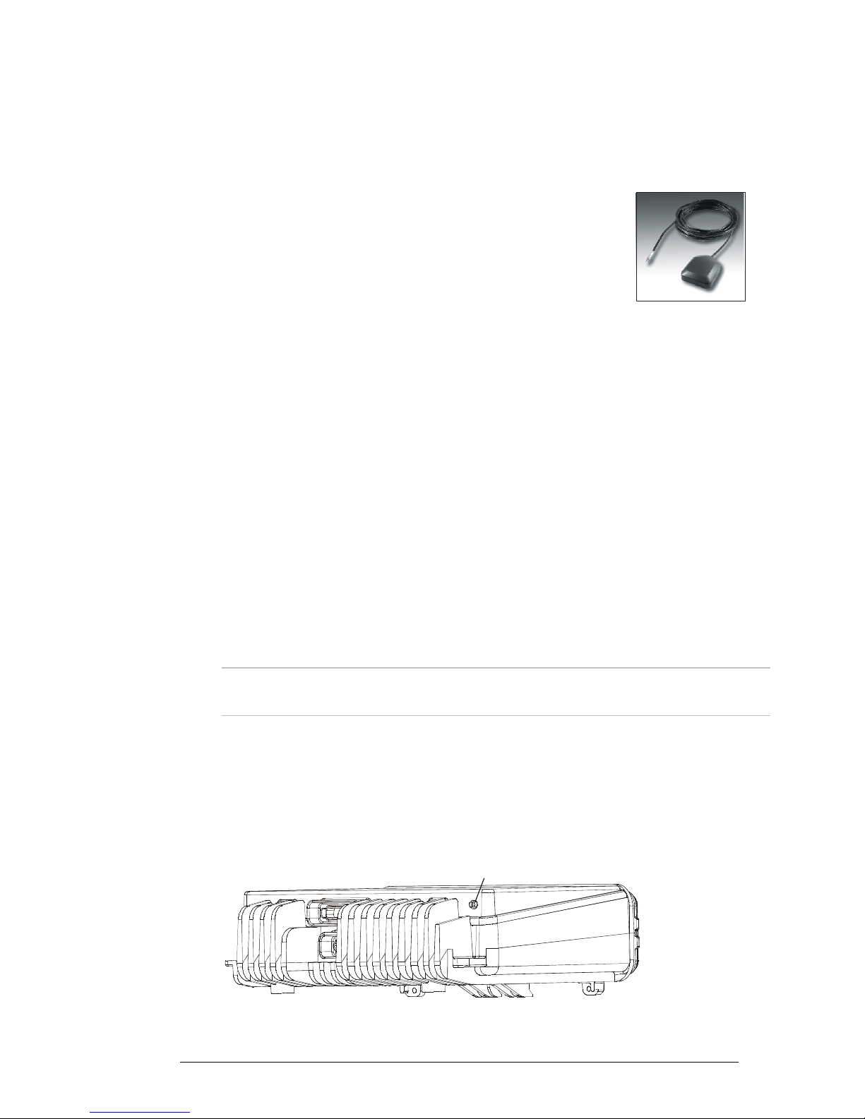
Antenna Description
The GPS antenna is a compact active omnidirectional antenna with magnetic
mounting, which attaches easily and firmly to vehicle’s steel body parts, even
when painted. The antenna will not attach to non-magnetic alloys (e.g.,
aluminum alloys), nor to parts made of composite materials (e.g., fiberglass).
The antenna connects to the GPS connector of the MICOM transceiver through a 5-meter (15 feet)
long coaxial cable, which is part of the antenna. This cable carries both DC power for the antenna,
and the received GPS signals.
The antenna is 42 mm wide by 50.5 mm long by 13.8 mm high (1.65”×1.99”×0.55”), and it requires
a minimal ground plane of 60 by 60 mm (2.36”×2.36”) to provide the specified performance.
Selecting a Proper Location for the GPS Antenna
GPS satellites transmit their special signals in the 1575 MHz range: such signals do not penetrate
conductive or opaque surfaces. When selecting the location of the GPS antenna, you should also be
aware that strong local interference as well as reflections from nearby objects may disrupt normal
reception and degrade the signal quality.
Thus, GPS antennas should be installed on horizontal surfaces, in a place that provides a clear view of
the sky, which, in as far as possible, is not obstructed by large objects. For example, the roof of the
passenger’s cabin is a good place for the GPS antenna.
Moreover, you should not park the vehicle under dense foliage or other cover, for example, in a
garage, if you want to get a position fix from your GPS receiver.
Note
When the GPS antenna is installed on a metal surface for prolonged periods, care
must be taken to insulate the antenna, to prevent galvanic corrosion.
Installing the GPS Antenna
Before starting, select a good location for the GPS antenna and plan the route for the cable
connecting it to your transceiver. The cable route should be selected in the same way you would
select the route for antenna cables: however, never run the GPS antenna cable in parallel to the
transceiver’s cables!
GPS Antenna
Connector
Figure 1. Location of GPS Antenna Connector on the MICOM
IMRMB007 3
Page 4

➤ To install the GPS antenna:
1. Place the antenna in the selected place, and make sure it attaches well to the surface.
2. Route the cable to the rear side of the MICOM transceiver, and if required, secure the
cable at several places.
3. Connect the coaxial connector of the antenna cable to the MICOM GPS connector.
Operating the GPS Receiver
GPS Menu
The GPS menu is displayed by selecting the GPS item on the FREQ or CH menu. The GPS menu
structure is shown in Figure 2.
CH Mode
MORE
Existing Menu
(Figure 2 or 3
in Supplement
6886872J01)
ECEF Format
X
Y
Z
DX
DY
DZ
MORE
TIME
DEV
FMT
GPS
LLA Format
FULL
VERT
DHOR
HOR
MORE
TIME
DEV
FMT
FREQ Mode
MORE
Existing Menu
MORE
(Figure 3 in
Supplement
6886872J01)
MORE
Figure 2. GPS Menu
The menu structure depends on the display format, ECEF or LLA, selected by the FMT item.
GPS Menu for the LLA Format
FULL
Alternating display of the absolute velocity (VEL) in the horizontal plane, and its
direction relative to the North (azimuth – AZIMTH).
VERT
DHOR
HOR
TIME
DEV
FMT
4 IMRMB007
Alternating display of altitude and up/down velocity.
Alternating display of North/South and East/West velocities.
Alternating display of latitude and longitude.
Display the time-of-day obtained from the GPS receiver.
Used to check that the GPS receiver is operating.
Toggle the display format (to ECEF).
Page 5

GPS Menu for the ECEF Format
X
Display the X coordinate.
Y
Z
DX
DY
DZ
TIME
FULL
Display the Y coordinate.
Display the Z coordinate (altitude).
Display the velocity along the X axis.
Display the velocity along the Y axis.
Display the velocity along the Z axis.
Display the time-of-day obtained from the GPS receiver.
Alternating display of the absolute velocity (VEL), and its direction relative to the
North (azimuth – AZIMTH).
DEV
FMT
Used to check that the GPS receiver is operating.
Toggle the display format (to LLA).
First-Time Operation
The internal GPS receiver is always powered when the transceiver is turned on. Therefore, if the GPS
antenna is connected and you are in a good place with a clear view of the sky, the GPS receiver can
start the satellite acquisition process as soon as the transceiver is turned on, and can then track the
satellites continuously.
Thus, the GPS item on the FREQ or CH menu only enables/disables the display of GPS data: the
result is that after selecting GPS, the GPS data can be immediately displayed, and is updated once
per second (time is updated once every 5 seconds).
Before using the GPS receiver, turn the MICOM transceiver on and let it operate for at least 15
minutes.
Operating Instructions
Switching to the GPS Display
Note
1. Select the GPS item by scrolling with the MORE key on the FREQ or CH menu, and then
pressing F2. You will see a message that indicates the current display format, GPS LLA or GPS
ECEF.
2. If necessary, switch to the alternate display format: press MORE as required to see FMT, and
then press the key next to FMT (F4).
3. If the GPS receiver operates normally and is ready, you will see the information selected the
last time the receiver has been used.
You cannot switch to the GPS display if you are using the ALE mode.
IMRMB007 5
Page 6

Selecting what to Display
1. Press the key next to the type of information you want to see: use Figure 2 to find the key to
be pressed.
2. The displayed information appears on the display and is automatically updated every second.
The time is updated every 5 seconds.
3. To change the display of GPS information, scroll to the desired item.
4. To cancel the display of GPS information, select any other menu except GPS.
Sending Your Position/GPS Position Requests
You can use the ALE AMD service to:
1. Send your position to any another destination (including one-to-many).
2. Request the position of another MICOM transceiver equipped with the optional GPS receiver.
You can make this type of request only when you call an individual station:
• If the request is made in the CALL mode (that is, before a link has been set up
between the two stations), a link will be set up and then the other station will
automatically return an AMD message with its latitude and longitude.
• If the request is made while in the LINK mode, the other station displays WHERE ARE
YOU?. In this case, the operator can manually send its position as explained below.
Note that the operations described above automatically set up a link between the two stations and
therefore it is necessary to disconnect the link when it is no longer needed. For this purpose, it is
recommended to enable HOME acknowledge, and/or enable the PTT time-out function.
Note
AMD messages with the GPS position do not enter the stack (the information such
message carries is good only at the time you got it): if you do not read the message
in time, you can no longer retrieve the message at a later time.
Thus, you must allow sufficient time for the destination station to read the position
message before when link is disconnected. This is particularly important when
HOME acknowledge is enabled: the message will disappear as soon as you
disconnect the link.
➤ To send your position report to other station(s):
1. Select the CALL mode (either from the ALE mode or the CHAN mode).
2. Select the destination address and/or the call type.
3. Select the PAGE selection mode.
4. Scroll until you see the I AM AT … message, and then send the message.
5. Your station sends the AMD message with your latitude and longitude.
6 IMRMB007
Page 7

➤ To automatically get the position of another station:
1. Select the CALL mode (either from the ALE mode or the CHAN mode).
2. Select the destination address (you can make only an individual call).
3. Select the PAGE selection mode.
4. Scroll until you see the RMT POS message, and then send the message.
5. Your station starts the link set up to the selected station; after the link is set up, you will
see the response AMD of the called station, which includes its latitude and longitude.
6. You may now continue with voice communication, or disconnect the link to the called
station.
➤ To send a position request to the station you are linked to:
1. While in the LINK mode, select the PAGE selection mode.
2. Scroll until you see the RMT POS message, and then send the message.
3. The called station displays WHERE ARE YOU?:
• To send an automatic response, the called operator select the PAGE selection
mode, and then sends the I AM AT … message as explained above.
• Alternatively, the called operator may answer with a voice message.
What to do if …
1. If the GPS display mode, GPS LLA or GPS ECEF, does not appear when switching to the GPS
display, scroll to the DEV item. You should see the GPS receiver type.
• If you see UNKNOWN, turn the MICOM transceiver off and after a few minutes turn
it back on. If the problem persists, the GPS receiver must be serviced.
• If you see NONE, your MICOM transceiver does not include the optional GPS
receiver.
2. If the requested information does not appear within 15 minutes, but the check in Step 1 above
is successful, check for proper connection of the GPS antenna cable to the rear GPS antenna
connector of the transceiver.
3. After checking that the antenna is properly connected, check that the GPS antenna did not
shift from its intended position, and has a clear view of the sky. Try to improve your location:
avoid locations near trees, high buildings, or steep hills.
IMRMB007 7
Page 8

8 IMRMB007
 Loading...