

Page 1
MODEL: EDM MM50 & MM80
MAGNETIC LINEAR SLIDING DOOR OPERATOR
Page 1
MAGNETIC LINEAR
SLIDING DOOR OPERATOR
INSTALLATION INSTRUCTIONS
_________________________________
MODEL:
EDM MM50 & MM80
Auto & Assist Version
(Japanese Type)
ORIGINAL INSTRUCTIONS
DATE: 2011
MICOM Autodoor | Osaka – Japan
No. MM0004
Page 2
MODEL: EDM MM50 & MM80
MAGNETIC LINEAR SLIDING DOOR OPERATOR
Page 2
WARNING: Avoidance of Injury, Electric shock and Fire
Installation and adjustment must be performed by approved personnel only.
Repair and/or alteration to the control box and motor are prohibited.
Power should be switched off during installation and service.
Switch power off when not in use.
Power supply 100V AC (Control Box Power Input AC 100V).
Keep away from any item which creates steam, heat or a humidifier.
Do not touch when a lightning storm occurs.
Should a burning smell be detected, switch power off at fuse.
Contact your MICOM representative immediately.
Do not put hands, flammable liquids, gases or items affected by high temperatures onto operator during
operation.
Do not spray pesticides or detergents onto operator directly.
CAUTION: Avoidance of Injury and Malfunctions
Ensure sliding door travel area is clear before switching power switch ON.
Do not hit or restrict door whilst moving.
Keep fingers, clothing and hair clear of belt and all moving parts.
Protective gloves should be worn when handling metal parts.
Page 3
MODEL: EDM MM50 & MM80
MAGNETIC LINEAR SLIDING DOOR OPERATOR
Page 3
CAUTION: Avoidance of Injury during Maintenance & Disposal
Risk of electrocution or personal injury can be avoided by switching mains power off for routine maintenance.
Risk of crushing or impact by a falling door panel or other solid object onto a person can be avoided by laying
any heavy object horizontally onto the floor at one the side of the working area. Risk of tripping or falling can
be avoided, by placing any removed objects to one side of the working area. A safe working area should be
maintained by cordon or other temporary boundary.
IMPORTANT NOTICE: Avoidance of Injury during Cleaning
To be performed by authorised personnel only:
With power OFF - Using neutral detergent, wet and twist a soft cloth to wipe clean the operator.
If power is not switched off before cleaning, there is risk of electrocution or personal injury due to door
movement.
IMPORTANT: NOTICE TO USER
Do not hang any items on the rail or door as this will cause improper operation of sensors and function of door
operator.
Teaching Stoke – Teaching will be operated after power on or a power cut. Please note that teaching is slower than
normal operation. Please refer to Section 2 for Teaching Operation.
Door frame may alter after original installation due to the condition of the building. Further adjustment may be needed
later after installation.
IF YOU HAVE ANY PROBLEMS – PLEASE SWITCH OFF THE PRODUCT AND CONTACT A MICOM
REPRESENTATIVE IMMEDIATLEY OR E-MAIL: info@micomautodoor.com
Page 4
MODEL: EDM MM50 & MM80
MAGNETIC LINEAR SLIDING DOOR OPERATOR
Page 4
AUTO Type
ASSIST Type
Push & Go Function
Vi-Part Synchronisation
Open Speed Adjuster
Closer Speed Adjuster
Open Timer
Ratchet Switch (Flip Flop) Function
Obstruction Protection
E-Lock LK1 - Fail Safe (Option)
Push & Go Function
Open Speed Adjuster
Partial Open Adjuster
Open Timer
Ratchet Switch (Flip Flop) Function
Hold Open Function – Setting By Hand
Free Stop Function – Setting By Hand
Obstruction Protection
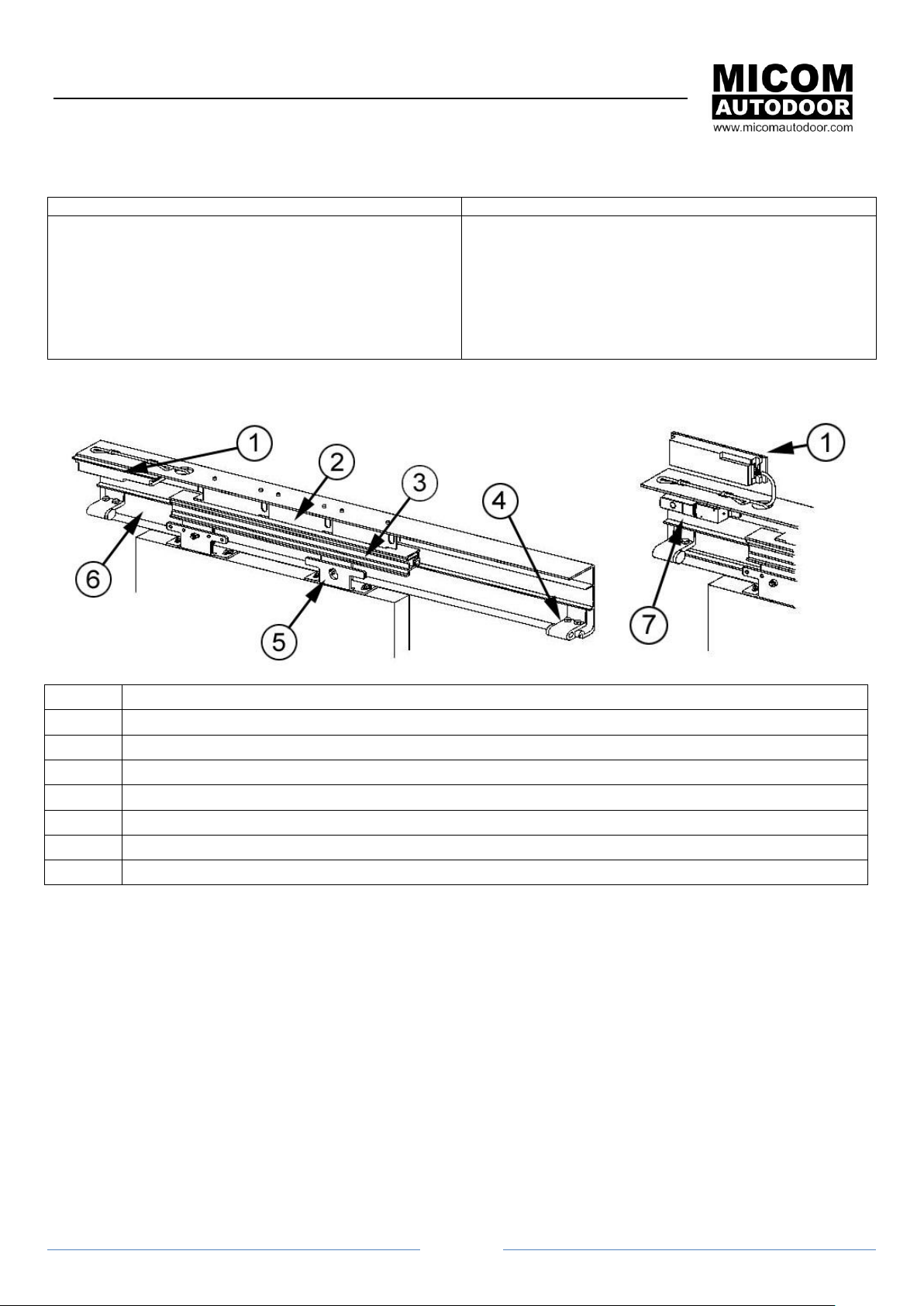
No.
Part Description
1
Control Box Assembly - MM50 & MM80 Assist Type
2
Magnetic Linear Motor MM50 & MM80
3
Moving Magnet
4
Stopper
5
Hanger Roller Assembly
6
Aluminium Rail
7
Electronic Lock (Option)
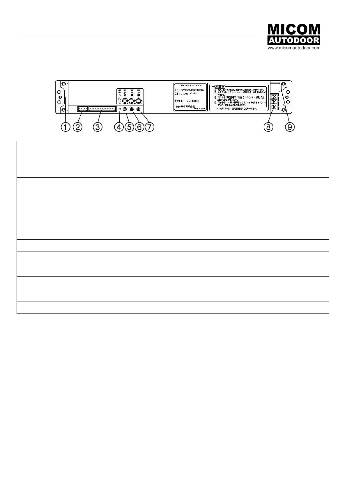
1. Operator Description (MM50 & MM80 from Japan)
1.1 Parts
Page 5
MODEL: EDM MM50 & MM80
MAGNETIC LINEAR SLIDING DOOR OPERATOR
Page 5
No.
Description
1
Motor Connection – Already Connected
2
E-Lock Connection (option)
3
Harness Connector – Signal Input / Output Data
4
LED -
Power On – Green LED will Flash 5sec. Then Green LED ON
Activation Signal / Safety Signal Input – Green LED OFF
LED RED ON – Over Heating Protection – Automatically Stop / Open
LED RED FLASHING SLOWLY – Obstruction Stop
LED RED FLASHING QUICKLY (with Beep) - Problem with E-Lock.
5
Open Speed Adjuster - 200~500mm/s (Default 400mm/s)
6
Model AUTO Type: Close Speed Adjuster - 200~500mm/s (Default 300mm/s)
6
Model ASSIST type: Partial Open Adjuster (0=50% ~ 10=100%).
7
Open Timer Adjuster - 1~10 sec. (Default 3sec.) & Ratchet.
8
Power Input – AC100V +/- & Earth
9
Power Switch – ON/OFF Input
1.2 Control Box MM50 & MM80 (Auto & Assist Type)
Page 6
MODEL: EDM MM50 & MM80
MAGNETIC LINEAR SLIDING DOOR OPERATOR
Page 6
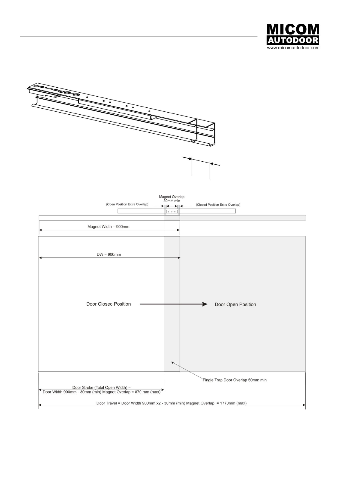
Cut to size for required installation.
Control and Linear Motor must be
protected from metal particles.
Applicable Door Width +/- 100mm (50mm Each Side) of Magnet Length.
Applicable Door:
Magnet Length 800mm = Door Width Min 700mm to Max 900mm
Magnet Length 900mm = Door Width Min 800mm to Max 1000mm
Magnet Length 1100mm = Door Width Min 1000mm to Max 1200mm
Note: Door position and alignment to
magnet can be left side, right side or
central depending on requirement.
2. Installation
2.1 Cutting Rail
2.2 Applicable Door
Page 7
MODEL: EDM MM50 & MM80
MAGNETIC LINEAR SLIDING DOOR OPERATOR
Page 7
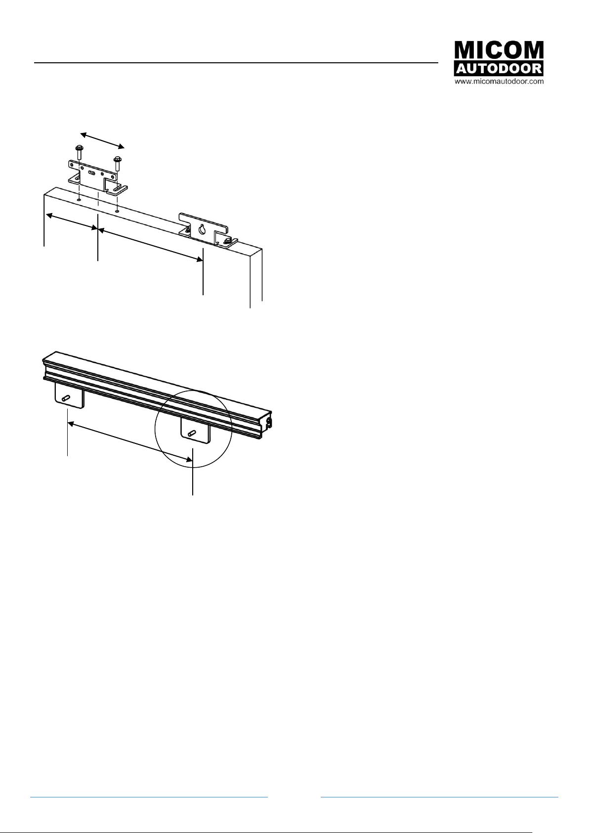
Position of hangers – Hangers should not be closer than
shown. If the pitch is too close, the door will not move
smoothly. Fix with M8 Bolts supplied.
Fixing Plate Pitch Adjustment – Loosen x2 M4 screws
and adjust the position of the fixing plate to same
distance as Hanger on door. (do not forget to re-tighten).
Note: Adjust Fixing Plate of Closing side only.
185mm
Hanger Pitch
Fixing Plate Pitch
2.3 Hanger Assemblies
2.3.1 Moving Magnet
Page 8
MODEL: EDM MM50 & MM80
MAGNETIC LINEAR SLIDING DOOR OPERATOR
Page 8
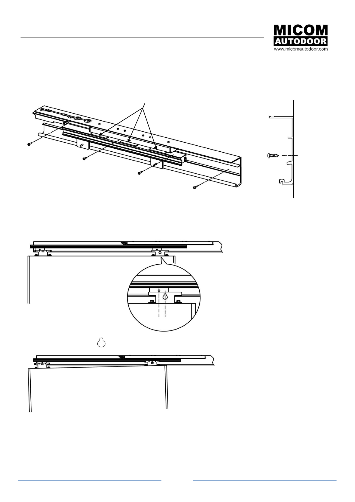
X3 Plastic Protection Plates – Do not remove
- To protect Linear Motor and Magnet
during installation
- Retain to future maintenance
2.4 Installation of Operator
Using appropriate fixing, attach operator to horizontal surface.
2.4 Installation of Door
Step1. Position door without fixing.
Step2. Hanging Door – Use 1
st
Page 9

MODEL: EDM MM50 & MM80
MAGNETIC LINEAR SLIDING DOOR OPERATOR
Page 9
Door mounted without tightening
hangers
Once bolts are tightened,
door and hangers will be
aligned.
Secure door leaf with M8 Nut
X3 Plastic Protection Plates
Step3. Hanging Door – Use 2
Step4. Tightening hangers with M8 nut.
nd
Page 10

MODEL: EDM MM50 & MM80
MAGNETIC LINEAR SLIDING DOOR OPERATOR
Page 10
2.5 Plastic Protection Plates
It is important to have x3 plastic protection plates in place when installation is being carried out. These plates protect
the Linear Magnetic Motor and the Moving Magnet from being in contacting with each other and causing damage. As
well as maintaining the correct 2mm distance between the Linear motor and moving magnet before the hanger
assemblies are tightened.
Note: Please keep protection plates for future maintenance requirement.
With door hung on Hanger bracket
but not tightened, ensure plastic
protection plates are in place.
Tighten M8 nut with flat washer
Maintain exact Horizontal and
Vertical alignment.
IMPORTANT: Confirm linear motor and moving
magnet are EXACTLY 2mm horizontally and
vertically aligned along length of motor. (use
plastic protection plate to check). Motor and
magnet should not be in contact with each other
at any point.
Remove plastic protection plate
2.6 Stopper Installation
Page 11

MODEL: EDM MM50 & MM80
MAGNETIC LINEAR SLIDING DOOR OPERATOR
Page 11
See Linear Motor –
There you will find
white markings.
These indicate the
overlap allowance
between the Linear
Motor and Moving
Magnet. As explained
below.
Note: If there is not enough overlap, this will be cause of defective operation.
Full Closed
X
Full Open
X
Correction
Position of Moving
Magnet
30mm Min.
Magnet Overlap
Distance
(White Mark)
Incorrect
Position of
Moving Magnet
Correction Position
of Moving Magnet
30mm Min
Magnet Overlap
Distance
(White Mark)
Incorrect
Position of
Moving Magnet
30mm
30mm
Motor
Motor
Moving Magnet
Moving Magnet
Motor
Motor
Moving Magnet
Moving Magnet
2.7 Moving Magnet – Set up & Correct Positioning
Page 12

MODEL: EDM MM50 & MM80
MAGNETIC LINEAR SLIDING DOOR OPERATOR
Page 12
1. Power Switch On/Off Plug In.
2. AC100V
3. AC100V
4. EARTH
Activation Input (SS)
Cable
Red
Activation Signal Input
Green
Common
Black
AC100V output (Japan use only)
White
AC100V output (Japan use only)
Threshold Safety Input (SB)
Cable
Red
Safety Signal Input
Green
Common
Black
AC100V output (Japan use only)
White
AC100V output (Japan use only)
Vi-Part & Function Input/Output - AUTO Type Only
Cable
Yellow
Closed End Signal Output
Blue
Common (Closed End Output)
Purple
Bi-Parting Signal Input
Orange
Bi-Parting Signal Output
Green
Ground
Notes:
- Model MM50 & MM80 is a NC (Normally Closed) circuit.
0 Voltage output of SS, SB, Vi-Part & Function Cables.
100V AC 1A output of Black and White cables to be
isolated (Japan use only).
SB =
Safety
SS =
Activation
Vi-Part & Function
(AUTO Type)
2.8 Wiring
2.8.1 Power Input & Mains Switch
2.8.2 Harness Wiring
Page 13

MODEL: EDM MM50 & MM80
MAGNETIC LINEAR SLIDING DOOR OPERATOR
Page 13
Learning CycleWith the Power ON/OFF Switch provided, power can be switched ON to begin
the Teaching Stoke process.
Teaching will begin once the power is turned ON. A full open and close cycle
stroke will be performed at SLOW speed.
CAUTION: When learning, allow the Door to Fully Open / Close. If sensors are
fitted, step back from the activation area. Do not obstruct the door when
teaching.
(a) Closed –
Activate to start the teaching process. The door will start to move SLOWLY in
the open direction. Once the door has reached its FULL open position, it will
return SLOWLY in the closing direction, until FULLY CLOSED.
Do not stand in the detection area when the door is teaching, as it will not
close.
(b) Not Closed –
The door will start to automatically close to the fully closed end. Once reaching
FULLY closed position, teaching can be performed as above.
(c) Closed with E-Lock -
If the operator is fitted with E-Lock, the teaching will always being with the door in FULLY closed and LOCKED
position.
(d) Teaching Complete Once the door has opened fully and then returned to the fully closed position and stopped – teaching is complete.
3. Operation
3.1 Teaching or Learning Operation
Each time the power is switched OFF (by switch or power cut), a teaching stroke must be carried out at the next
power ON.
3.1.1 Learning Operation - Door Starting Position:
3.2 Normal Operation
After the teaching process is successfully completed, the operator will be ready to accept all customary activations.
With door in closed position, it can be activated to open. After pre-set open time, the door will close. It will re-open if
any activation signal or safety signal is turned on. If there is no such activation, the door will close fully.
With an E-Lock fitted, the door will lock after it is fully closed.
CAUTION: If the door does not stop at the closed end position and re-opens automatically. The operator is not
installed correctly. Please contact your MICOM Representative or email: info@micomautodoor.com
Page 14

MODEL: EDM MM50 & MM80
MAGNETIC LINEAR SLIDING DOOR OPERATOR
Page 14
Push to Open
Push to Close
3.3 Activation & Functions
Not only can the operator be activated by all customary sensors and activation devices, but also by hand activation.
Please see supporting Wiring Diagrams for accessory options.
MM50 & MM80 incorporates an assist activation function as standard. Moving the door by hand in the direction of
open for 2cm will activate the door. After pre-set open time it will close automatically.
a. Activation by Hand (Push & Go) (Auto & Assist Type) - By simply pushing the door in the open direction for
2cm, the operator will be activated and carry out automatic open and close cycle.
b. Hold Open by Hand (Assist Type) – By holding the door in the full open position, an audible signal will be
heard. The door is now in Hold Open. To close, again simply pull the door, no more than 2cm and the door
will automatically close.
c. Free Stop (Assist Type) – Once door is in motion, hold the door (by handle if fitted) at any position before it
reaches the full open position. The door will stop and be free to move by hand as a manual sliding door. To
re-activate, return the door to full closed position.
d. Partial Open (Assist Type) - Partial Open is adjustable by the Partial Open adjuster. Adjustable range 0 = 50%
to 10=100% Open. Factory Setting at 100% Full Open. Partial open is a fixed setting by control. The use of a
Partial Open Switch Selection is not applicable. Partial Open % setting is effective after activation through SS
input. When activation by hand (Push & Go), Partial Open % setting is ignored and door opens to 100% Full
open.
e. Ratchet Function (Auto & Assist Type) – By use of the Open Timer Setting Adjustment – Turning the timer to
max, the Ratchet Function will be enabled. Ratchet operation enables the door to be opened and closed with
a switch.
Caution: It is not recommended to use an activation sensor for Ratchet Function. See Section 3.3
Ratchet Function with E-Lock – it is not possible to use Assist Activation (Push & Go) feature as the door
cannot be opened by hand. The door must only be activated by a switch.
3.4 Obstruction Detection
EDM MM Controller is always calculating door position and door speed. If the door hits an obstruction during closing,
the door will stop immediately with light force and reverses to the open position.
The door will then close after the preset open time at slow speed. Should the door find the obstruction again, the door
will stop. Door will return to operation upon the next activation signal. With the obstructing cleared, normal operation
will continue.
Page 15

MODEL: EDM MM50 & MM80
MAGNETIC LINEAR SLIDING DOOR OPERATOR
Page 15
4.1 OPEN SPEED – ADJUSTER 1.
Open / Close Speed is adjustable by the speed adjuster. Turning Right = Faster (F).
Adjustable range is 200~500mm/s. Factory Setting Speed: Open Speed at 400mm/s /
Close Speed at 300mm/s.
4.2.1 AUTO TYPE: CLOSE SPEED – ADJUSTER 2.
Close Speed is adjustable by the speed adjuster. Turning Right = Faster (F). Adjustable
range is 200~500mm/s. Factory Setting Close Speed at 300mm/s
CAUTION: It is recommended not to set the Close Speed to max for safety or pedestrians.
4.2.2 ASSIST TYPE: PARTIAL OPEN ADJUSTER 2.
Partial Open is adjustable by the Partial Open adjuster. Adjustable range 0 = 50% to
10=100% Open. Factory Setting at 100% Full Open.
Note: Partial open is a fixed setting by control. The use of a Partial Open Switch Selection
is not applicable.
4.3 OPEN TIMER & RATCHET – ADJUSTER 3.
Open time will begin when the door has reached its full open position. (Turning Right =
Longer (L)). Adjustable range is 1~10sec. (Factory Setting Open Time: 2~3sec)
4.3.1 Ratchet Function
Turning the adjuster to max, open time will become infinite (no limit). The door will stop at
the open position which is known as Ratchet Function (or Flip Flop). See Section 2.5
CAUTION: Please take care to turn the adjusters gently with a thin screwdriver. Do not turn the adjuster
strongly with force as the adjuster will be broken.
4. Operation Adjustment
Page 16

MODEL: EDM MM50 & MM80
MAGNETIC LINEAR SLIDING DOOR OPERATOR
Page 16
Plug No.3 – Close Pressure
Close Pressure
Connected
On = ACTIVE (Factory Setting)
Disconnected
Off = NOT ACTIVE
Breaking
Level
Plug No.1
White
Plug No.2
White
Applicable Door
MM50 Single
MM80 Single
Heavy
1
Connected
Disconnected
40-50kg
40-80kg
2 (Factory Setting)
Connected
Connected
30-40kg
30-40kg
3
Disconnected
Connected
20-30kg
20-30kg
Light
4
Disconnected
Disconnected
20-25kg
20-25kg
Plug No.1 Adjustment
2 pin / White
Plug No.2 Adjustment
3 pin / Black
Plug No.3 – Close Pressure
2 pin / Black
4.4 AUTO Type - Open / Close Breaking & Sensing Function (with Bi-Part)
4.4.1 Close Pressure Adjustment
4.4.2 Open / Close Breaking Force Adjustment
NOTE: Above door size and weight should be used as a guide only. Please check breaking force setting by sight.
For Example: Door Open / Close Force Level ‘2’ = Factory setting Plug no.1 & Plug no.2 – Connected.
If the braking is too weak (door hits a little hard) - Set to level ‘1’ = Plug no.2 – Disconnect & Plug no1 - Connected.
If the breaking is too hard (door jumps) – Set to level ‘3’ = Plug no.1 – Disconnect & Plug no. 1 – Connected.
Page 17

MODEL: EDM MM50 & MM80
MAGNETIC LINEAR SLIDING DOOR OPERATOR
Page 17
Plug No.3 – Close Pressure
Close Pressure
Connected
On = ACTIVE (Factory Setting)
Disconnected
Off = NOT ACTIVE
Breaking
Level
Plug No.1
White
Plug No.2
White
Applicable Door
MM50 Single
MM80 Single
Heavy
1
Connected
Disconnected
40-50kg
40-80kg
2 (Factory Setting)
Connected
Connected
30-40kg
30-40kg
3
Disconnected
Connected
20-30kg
20-30kg
Light
4
Disconnected
Disconnected
20-25kg
20-25kg
Plug No.1 Adjustment
2 pin / White
Plug No.2 Adjustment
3 pin / Black
Plug No.3 – Close Pressure
2 pin / Black
4.5 ASSIST Type - Open / Close Breaking & Sensing Function
4.5.1 Close Pressure Adjustment
4.5.2 Open / Close Breaking Force Adjustment
NOTE: Above door size and weight should be used as a guide only. Please check breaking force setting by sight.
For Example: Door Open / Close Force Level ‘2’ = Factory setting Plug no.1 & Plug no.2 – Connected.
If the braking is too weak (door hits a little hard) - Set to level ‘1’ = Plug no.2 – Disconnect & Plug no1 - Connected.
If the breaking is too hard (door jumps) – Set to level ‘3’ = Plug no.1 – Disconnect & Plug no. 1 - Connected
Page 18

MODEL: EDM MM50 & MM80
MAGNETIC LINEAR SLIDING DOOR OPERATOR
Page 18
Problem
Possible Solution
Does not power on. LED does not light.
Check wiring or power source. Wire to controller is
disconnected?
Keeps Beeping (RED LED blinking quickly)
E-Lock Error. Wire to E-Lock is disconnected?
Dead Bolt is not located into hole for Lock?
Does not open after sensor (SS) is activated
Sensor wire is not connected?
Sensor is connected to Safety Wire (SB)?
Does not open even if Safety (SB) is connected
Sensor (SS) is disconnected?
Door is closed?
Door Opens (from fully closed) when Safety (SB) is
activated
Safety Sensor is connected to Activation wire (SS)?
Does not open with wireless touch switch or button
Wire from receiver of touch switch is disconnected?
There is an obstruction stopping signal?
Battery and direction are ok?
Channel of switch and received is same?
Model
EDM MM-50
EDM MM-80
Application
ASSIT=Single | AUTO=Single or Vi-Part
ASSIT=Single | AUTO=Single or Vi-Part
Door Weight (max)
20-50 Kg per Leaf
20-80kg per Leaf
Power Supply
100V AC ( Control 100V AC +/- 10%) 50/60Hz Max 4A
Open Speed
Adjustable 200 ~ 500mm/s (Factory Default 400mm/s)
Closing Speed
Adjustable 200 ~ 500mm/s (Factory Default 300mm/s)
Open Timer
1~10sec Max – (Factor Default 3sec) & Ratchet (Flip Flop)
Motor
Brushless Magnet Movable Linear DC Motor
Environment (Temp)
Ambient temperature -10C ~ +40C
(no (condensation or icing)
Ambient humidity 30% ~ 85% RH (no hazardous materials must be present in the
atmosphere)
5. Trouble Shooting
6. Specification
6.1 Technical
Page 19

MODEL: EDM MM50 & MM80
MAGNETIC LINEAR SLIDING DOOR OPERATOR
Page 19
A. ACTIVATION SIGNAL INPUT
RED = ACTIVATION (SS)
GREEN = COM
WHITE – 100VDC (Japan Only)
BLACK – 100VDC (Japan Only)
B. THRESHOLD SAFETY SIGNAL INPUT
RED – ACTIVATION (SB)
GREEN – COM
WHITE – 100VDC (Japan Only)
BLACK – 100VDC (Japan Only)
C. VI-PART & FUNCTION SIGNAL
INPUT/OUTPUT
BLUE – COM (CLOSE END OUTPUT)
YELLOW – CLOSED END OUTPUT
GREEN – COM
ORANGE – VI-PARTING OUTPUT
PURPLE – VI-PARTING OUTPUT
Note:
Model MM50 & MM80 is a NC (Normally
Closed) circuit.
0 Voltage output of SS, SB, Vi-Part &
Function Cables.
100V AC 1A output of Black and White
cables to be isolated (Japan use only).
MM50 & MM80 – Harness Wiring & Connections
Page 20

MODEL: EDM MM50 & MM80
MAGNETIC LINEAR SLIDING DOOR OPERATOR
Page 20
Basic Wiring – Single & Bi-Part - Activation & Safety
Vi-Parting Synchronization (Bi-Part)
Page 21

MODEL: EDM MM50 & MM80
MAGNETIC LINEAR SLIDING DOOR OPERATOR
Page 21
Notes: When door is synchronized using Vi-Parting connection, it is possible to include a switch to change operation
for Single Door use. SWITCH ON = Synchronization | SWITCH OFF = Individual
Notes: Door 1 will not open if door 2 is open. Door 2 will not open is door 1 is open.
Vi-Parting Synchronization (Bi-Part) or Individual Operation by Switch
Interlock
Page 22

MODEL: EDM MM50 & MM80
MAGNETIC LINEAR SLIDING DOOR OPERATOR
Page 22
Wiring: Yellow – Closed End Signal / Blue – Com (Closed End Signal)
Load Capacity: 0.3A AC125V / 1A / DC24V
Notes: Door will open and close when access is authorized from card reader, keypad or other security system.
Closed End Output Signal – Digital Counter (Option)
Security Wiring (Option) – Access Control
Page 23

MODEL: EDM MM50 & MM80
MAGNETIC LINEAR SLIDING DOOR OPERATOR
Page 23
Notes: Door will open and close by activation only during pre-set time.
Notes: Entering room is restricted with timer device. Exit from room is allowed.
Security Wiring (Option) – Timer
Security Wiring (Option) – Timer Access
Page 24

MODEL: EDM MM50 & MM80
MAGNETIC LINEAR SLIDING DOOR OPERATOR
Page 24
MM50 & MM80
Rail Length (mm)
Entrance Width (mm)
Standard Size Option
Single - Left /
Right
1666 / 1925 /
2232 / 2512 /
2710
833 / 962.5 / 1116 / 1256 / 1355
Cut to Size (Made to Order)
Single
1500 - 1800
750 - 900
1801 - 2200
900 - 1100
2201 - 2710
1100 - 1350
2711 - 3200
1355 - 1600
NOTE: E-Lock is available with AUTO type only. Assist type
does not support E-Lock. E-Lock offers LK1 FAILSAFE
(UNLOCK without power) function only.
If an E-lock is fitted, it is not possible to open the door by hand. The
door will be unlocked upon an activation signal to the controller and
open automatically. Once a full open and close cycle has been
performed, the door will lock with E-lock once fully closed.
If there is a problem with the E-Lock, the controller will show this
when either in teaching mode or during normal operation.
7.1 Teaching with E-Lock
LED will flash RED with Buzzer.
Lock output Signal
(Option – With Counter)
Wiring:
Red – Lock output
signal
Black – Com
Load Capacity: 0.3A /
AC125V / 1A / DC24V
E-Lock Harness
E-Lock Body
6.2 Applicable Door Size
7. Electronic Lock (Option)
Page 25

MODEL: EDM MM50 & MM80
MAGNETIC LINEAR SLIDING DOOR OPERATOR
Page 25
8. Health & Safety
It is recommended that the following installation guide lines be followed in compliance with safety standards.
8.1 Safety During the Open Cycle
Provision should be made to deter person from occupying the area through which the door travels during the open
cycle. A ‘keep clear’ sign is recommended to be fixed to the screen or wall across which the door travels. Where
practical, the following is recommended to be fitted: Barrier or Pocket Screen installed along the line of the opening
leaf. (Pocket Screen: H=1500mm min from finished floor level)
8.2 Safety During the Close Cycle
Provision should be made using one of the following, to prevent a door shutting on traffic during the closing cycle. A
Safety Beam is recommended to be positioned between the jambs at a height of 300mm – 600mm above the finished
floor level. Alternately we recommend the use of an appropriate presence sensing safety device covering the
threshold area, in relation to where a risk assessment shows there is a significant proportion of traffic using the
entrance /exit doors, who are potentially vulnerable (e.g. elderly, infirm, disabled or very young).
8.3 End User - Occupier Safety Tests - Recommended
To ensure safe daily use of our automatic door system, we recommend the follow be applied in compliance with safety
standards.
The occupier is responsible for the undertaking of the following test procedure, which should be carried out at least
weakly, unless a different schedule of tests is identified in the risk assessment priory to installation.
1. There should be no notice boards, literature racks, merchandise displays or other distractions or obstructions in the
vicinity of the door which may congest or inhibit traffic flow.
Automatic Activation Device Test:
2. Test sensors by walking towards the door opening. The door should start to open when a person is approx 1400mm
(5ft) from the door. The door should slide smoothly to the open position and stop without impact
3. Step out of the activation zone. After a time delay (normal 1s ~ 5s) the door should close smoothly.
4. Repeat steps 2 and 3 on the other side of the opening, if the door has two way operation.
Safety Devices
5. Safety Beams. If safety beams are fitted, place a test object on the threshold at the full open position, step out of
the diction area and confirm the door remains open.
General Test
6. Check that the door area has no tripping or slipping hazards
7. Check all door panels for cracked or broken glass.
8. Check doors have signs correctly displayed at recommended viewing heights if fitted
9. Check the position and security of associated screens and barriers if fitted.
10. Check the operation of manual activation, remote activation or other stop devices if fitted.
11. Check and remove any distractions / obstructions in the vicinity of the doors.
Page 26

MODEL: EDM MM50 & MM80
MAGNETIC LINEAR SLIDING DOOR OPERATOR
Page 26
Authorised Technician Check List
Applicable to Sliding, Telescopic, Curved, Prismatic and Folding Door
Site:
Serial No:
Door Type:
Opening Width:
Time
Open Time: sec
Closing Time: sec
Hold Open Time: sec
Closing Energies (Commissioning Only)
At Low Speed: J
At Max Speed: J
Static Entrapment Force: N
Activation Distances
Straight Approach: m
Side Approach: m
Safety Device/s
Hold Open Beams
Number Fitted:
Height/s above Floor Level: m
Presence Sensors
Field Width: m
Field Depth: m
Hold Open time: sec
Drawing in protection
Leading Stile to Jamb: mm
Outer Stile to mullion: mm
Barrier Rail / Safety Side Screen: Fitted / Not Fitted
Escape System
Fail Open: Active / Not Active
Breakout: Fitted / Not fitted
Break out force: N
Signage Fitted: Y/N
General Comments:
Name:
Time:
Signed:
Date:
8.4 Installation Check List
It is recommended that the following is carried out by the authorised technician and that the following information is
provided during installation commissioning and at each annual safety inspection. We therefore provide the basis for
such checks to be carried out in compliance with safety standards.
(Example)
 Loading...