

Micom 3f, 3T, 3R, MICOM-3T M90AMNOKV5-K, MICOM-3F M91AMNOKV5-K Owner's Manual
...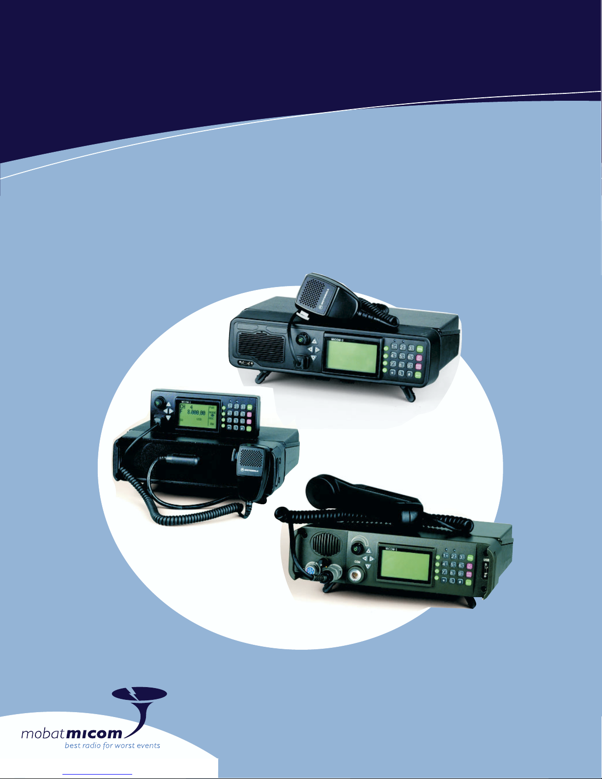
MICOM-3F/3T/3R
HF-SSB Transceivers
Owner’s Guide
Part I - Operation & Installation
6886867J01A


MICOM-3F/3T/3R
HF-SSB Transceivers
MOBAT USA
1720 West Paul Dirac Drive
Tallahassee, 32310 FL
United States of America
Owner’s Guide
Part I – Operation & Installation
Cat. No. 6886867J01A


Table of Contents
Table of Contents
Page
Introduction .....................................................................................................................1
MICOM-3 HF-SSB Radio Features......................................................................2
MICOM-3 Options and Accessories....................................................................3
Familiarization with MICOM-3 Radios ..............................................................................4
MICOM-3F Front Panel......................................................................................4
MICOM-3T Front Panel......................................................................................5
MICOM-3R Front Panel .....................................................................................6
Rear Panel (All Models) ......................................................................................7
LCD Display Functions .......................................................................................8
General Procedures............................................................................................10
Using the External (USB) Keyboard Option (MICOM-3F/3R only) .......................13
The Menu ..........................................................................................................14
Basic Operating Instructions .............................................................................................16
Turning the Radio On and Off............................................................................16
Transmitting and Receiving.................................................................................17
Using the Channel Mode....................................................................................18
Using the Frequency Mode ................................................................................22
Using the Scan Mode .........................................................................................30
Using the BIT Mode ...........................................................................................31
Locking the Radio...............................................................................................32
Changing the Password.......................................................................................33
Using Automatic Link Establishment (ALE).........................................................................34
ALE Capabilities and Features.............................................................................34
Using ALE Functions in the Channel Mode .........................................................43
Entering the ALE Mode.......................................................................................43
Receiving and Transmitting Calls in ALE Mode....................................................45
Using the Programming Mode ..........................................................................................78
Programming the Radio Parameters ..................................................................................81
Programming Channels.......................................................................................82
Selecting Radio Parameters.................................................................................84
Setting Radio Options.........................................................................................86
ALE Programming .............................................................................................................87
Programming Nets..............................................................................................88
Setting the Net Options ......................................................................................90
Directory Parameters..........................................................................................90
AMD Message Configuration ..............................................................................91
ALE Options Configuration .................................................................................91
Auto Dial Parameters..........................................................................................93
i

MICOM-3F/3T/3R HF-SSB Owner’s Guide
Storing ALE parameters.......................................................................................93
Using the New Station Address Filter ..................................................................94
Using the VP-116 Mini Voice Privacy Unit........................................................................95
Introduction .......................................................................................................95
Specific Parameters for Privacy Operation ..........................................................95
Connecting/Disconnecting the VP-116 Unit........................................................95
Using the VP-116 Unit .......................................................................................96
Programming the VP-116 Unit from the MICOM-3 ............................................97
Using the Vocoder............................................................................................................100
Introduction .......................................................................................................100
Using the Vocoder..............................................................................................100
Programming the Vocoder..................................................................................102
Using the MICOM-3 GPS Receiver ...................................................................................104
Introduction .......................................................................................................104
GPS Receiver Functions......................................................................................104
GPS Antenna......................................................................................................105
Operating the GPS Receiver ...............................................................................106
Installation........................................................................................................................110
General ..............................................................................................................110
Base Station Installation ......................................................................................111
MICOM-3R Installation ......................................................................................112
MICOM-3F Installation.......................................................................................113
MICOM-3T Installation.......................................................................................113
Installation Procedures .......................................................................................115
Connectors.........................................................................................................120
Maintenance ....................................................................................................................124
Introduction .......................................................................................................124
Preventative Maintenance ..................................................................................124
Using BIT ...........................................................................................................125
Troubleshooting .................................................................................................127
Service ...............................................................................................................129
Appendix A micomTrooper 3 5-50 Watt HF-SSB Backpack Transceiver ...........................130
Introduction .......................................................................................................130
Preparing the micomTrooper 3 for Operation.....................................................134
Operating Instructions ........................................................................................140
Preparing micomTrooper 3 for Static Operation .................................................141
Using the micomTrooper 3 Battery Charger, FLN9541 .......................................142
List of Procedures .............................................................................................................144
ii

Acronyms
AGC Automatic Gain Control
ALE Automatic Link Establishment
AMD Automatic Message Display
AME Amplitude Modulation Equivalent
ARQ Automatic Repeat Request
BITE Built-In Test Equipment
CW Continuous Wave
DSP Digital Signal Processing
DTCXO Digitally Temperature Controlled Crystal Oscillator
FEC Forward Error Correction
FSK Frequency Shift Keying
GND Ground
Acronyms
GPS Global Positioning System
HF High Frequency
HSM High Speed Modem
LED Light Emitting Diode
LQA Link Quality Analysis
LSB Lower Side Band
LSM Low Speed Modem
MCW Modulated Continuous Wave
MRC MICOM Radio Control Application
OCXO Oven Controlled Crystal Oscillator
PEP Peak Envelope Power
PLL Phase Lock Loop
PTT Push To Talk
RGC Receiver Gain Control
RSS Radio Service Software
RTTY
SINAD
Radio Telex Teletype
Signal to Signal Noise Distortion Ratio
SSB
USB
Single Side Band
Upper Side Band
VP Voice Privacy
VSWR
XMIT
Voltage Standing Wave Ratio
Transmit
iii

MICOM-3F/3T/3R HF-SSB Owner’s Guide
Performance Specifications
MICOM-3F – Model M90AMNOKV5-K
MICOM-3T – Model M91AMNOKV5-K
MICOM-3R – Model M95AMNOKV5-K
General
Transmit Frequency Range
Receive Frequency Range
RF Input Impedance
Number of Channels
Scanning
ALE
Frequency Stability
Frequency Drift (Aging)
Synthesizer Lock Time
Frequency Resolution
Operating Temperature Range
Storage Temperature Range
Humidity
1.6 to 30 MHz
0.1 to 30 MHz (0.1 to 1.6 MHz reduced
performance)
50 Ω
200 simplex or half duplex, user programmable
5 groups with up to 100 channels per group,
including 1 guard channel.
Programmable scan rate: 1 to 5 sec. per
channel, in 1 sec. steps
Per FED-STD-1045B and MIL-STD-188-141B,
JITC certified
0.6 ppm (0.1 ppm optional) @ -30° to 60°C
1 ppm/year
10 msec. max.
10 Hz
-30° to +60°C
-40° to +85°C
Max. 95% @ 50°C
iv
Remote Control Interface
Modes of Operation
Operating Voltage
Dimensions
MICOM-3F
MICOM-3R
MICOM-3T
RS-232C (optional)
• ]3E SSB
• R3E PILOT
• H3E AME
• J2A CW
• J2B RTTY, ARQ, FEC, PACKET, MCW
• B8C FAX, DATA, FSK
13. 8 VDC ±20%, negative ground
92 H × 302 W × 270 D mm
(3.7 H × 11.9 W × 10.7 D inch)
92 H × 302 W × 285 D mm
(3.7 H × 11.9 W × 11.3 D inch)
92 H × 302 W × 285 D mm
(3.7 H × 11.9 W × 11.3 D inch)

Performance Specifications
Current
Consumption
@ 13.8 VDC
FCC
Information
Weight
MICOM-3F
MICOM-3R
MICOM-3T
Transmit
Voice (125 W P.E.P)
2 Tones (125 W P.E.P)
Single Tone
Receive
Full Audio
Squelch
Transmitter Peak Envelope Power
(P.E.P)
Frequency Range
Emissions Authorized
Applicable Parts of FCC Rules
FCC Type Acceptance Number
5.7 kg (12.5 lb)
5.9 kg (13 lb)
5.8 kg (12.8 lb)
14 A (see Note 1 on page vii)
23 A
28 A
3 A (see Note 1 on page vii)
2.2 A (see Note 1 on page vii)
125 W
1.6 to 30 MHz
J3E, R3E, H3E, J2A, J2B, B8C
15, 80, 90
Military and
Industrial
Standards
Standard for Stability
0.1 ppm High Stability Option
Vibration
Shock
Rain
Dust
Salt Fog
The MICOM-3 also meets the EIA-RS152B for shock, vibration and applicable test
procedures, US FCC for channel occupancy, spurious, interference and frequency
tolerance. It is manufactured according to the demanding standards of ISO 900
and EMC (Electromagnetic Compatibility).
ABZ9QCC1635
ABZ9QCC1634
US MIL-STD 810C Method 514.2
US MIL-STD 810D 514.3
US MIL-STD 810E 514.4
US MIL-STD 810C Method 516.2
US MIL-STD 810D 516.3
US MIL-STD 810E 516.4
US MIL-STD 810C Method 506.1
US MIL-STD 810D 506.2
US MIL-STD 810E 506.3
US MIL-STD 810C Method 510.1
US MIL-STD 810D 510.2
US MIL-STD 810E 510.3
US MIL-STD 810C Method 509.1
US MIL-STD 810D 509.2
US MIL-STD 810E 509.3
v

MICOM-3F/3T/3R HF-SSB Owner’s Guide
Transmitter
Output Power
Reduced Power Levels
Audio Bandwidth
Voice
CW
Low Speed Data
High Speed Data
Audio Bandwidth Ripple
Intermodulation
Harmonic Emissions
Spurious Emissions
Carrier Suppression
Undesired Sideband Suppression
125 W P.E.P and average
25 W, 62 W, 100 W (MRC or RSS
programmable)
350 to 2700 Hz at -6 dB
650 to 1150 Hz
1450 to 1950 Hz
350 to 3300 Hz (see Note 2 on page vii)
3 dB
• -31 dB/P.E.P
• -35 dB/P.E.P typical (see Note 1 on page vii)
• -64 dB/P.E.P
• -70 dB/P.E.P typical (see Note 1 on page vii)
• -64 dB/P.E.P
• -70 dB/P.E.P typical (see Note 1 on page vii)
-50 dB/P.E.P
-55 dB/P.E.P
Receiver
Audio Distortion
1/2 Power Microphone Sensitivity
Hum & Ripple
Inband Noise
TX/RX Switching Time
Tx Tuning Adjustments
Sensitivity (SINAD) SSB
1/2 Rated Power Sensitivity
Selectivity
Image Rejection
IF Rejection
Undesired Sideband Rejection
Spurious
Intermodulation
2.5%
25 to 125mV (RMS)/600 Ω
-50 dB
-60 dB (30 Hz BW)
10 msec
None
• 0.5 µV for 10 dB SINAD
• 0.35 µV typical (see Note 1 on page vii)
• 0.1 to 1.6 MHz with reduced performance
1 µV for 2.5W audio at speaker
-6 dB @ 350 to 2700 Hz
-60 dB @-1 kHz; +4 kHz
-80 dB
-85 dB
-55 dB @ -1 kHz
-80 dB
-80 dB
vi
Crossmodulation
Desensitization
Reciprocal Mixing
Audio Power at Speaker
-100 dB @ 100 kHz
-100 dB @ 100 kHz
-100 dB @ 100 kHz
5W @ 2.5% distortion

Performance Specifications
RGC Range
RGC Time Constants
Voice
5 µV to 1V (2 dB change in output level)
Attack time 10 msec
Release time 1500 msec
Data
Attack time 10 msec
Release time 10 msec
Squelch
Clarifier Range
Constant SINAD (digital)
±200 Hz in 10 Hz steps (see Note 2 on page
vii)
Controls
Receiver Tuning Adjustments
Preselector Sections
Maximum Antenna Input
Standard and optional: Volume, on/off, scroll, squelch, scan, USB/LSB, call,
None
Sub-octave (1.6 MHz to 30 MHz range)
20 kV transient, 100V RMS for 2 minutes
monitor, priority, function and accessory/programming connector
Note 1: Values noted as "Typical" are valid over 90% or more of the frequency range.
Note 2: Optional for authorized dealers only.
Specifications subject to change without notice.
vii
MICOM-3F/3T/3R HF-SSB Owner’s Guide
Warnings, Cautions and Notes
The following notations are used to place special emphasis on procedures, or to call attention to
precautionary measures.
An operating procedure, practice and so forth, which if not followed
correctly, could result in personal injury, or loss of life.
Warning
BEFORE USING THIS RADIO, READ THIS BOOKLET WHICH CONTAINS
IMPORTANT OPERATING INSTRUCTIONS FOR SAFE USAGE AND RF
Caution
ENERGY AWARENESS AND CONTROL INFORMATION FOR
COMPLIANCE WITH RF ENERGY EXPOSURE LIMITS IN APPLICABLE
NATIONAL AND INTERNATIONAL STANDARDS.
Note
An operating procedure, condition and so forth, to which special attention should
be paid.
General Safety Precautions
The following are general safety precautions that are not related to any specific procedures and
therefore do not appear elsewhere in this publication. These are recommended precautions that
personnel must understand and apply, in addition to the precautions listed in the Information for Safe,
Efficient Operation section (page ix).
Do not touch the antenna and the RF connectors when the transceiver
operates.
Warning
High
Voltage
During transmission, high RF voltages appear at the RF connectors, the
antenna cables, and on the antenna itself. These voltages may cause
severe injury or even death on contact.
Operating and maintenance personnel must be familiar with the
applicable safety requirements before attempting to install or operate the
transceiver. Severe injury or death could result from failure to comply
with the safety practices.
viii

Information for Safe, Efficient Operation
Information for Safe, Efficient Operation
Product Safety and RF Exposure for Mobile Two-Way Radios
Installed in Vehicles or as Fixed Site Control Stations
BEFORE USING THIS RADIO, READ THIS BOOKLET WHICH CONTAINS
IMPORTANT OPERATING INSTRUCTIONS FOR SAFE USAGE AND RF
ENERGY AWARENESS AND CONTROL INFORMATION FOR
Caution
COMPLIANCE WITH RF ENERGY EXPOSURE LIMITS IN APPLICABLE
NATIONAL AND INTERNATIONAL STANDARDS.
The information provided in this document supersedes the general safety information contained in
user guides published prior to February 2002.
Compliance with RF Energy Exposure Standards
NOTICE
MOBAT USA
1720 West Paul Dirac Drive
Tallahassee, 32310 FL
United States of America
This radio is intended for use in occupational/controlled applications where users have
been made aware of the potentional for exposure and can exercise control over their
exposure. This radio device is NOT authorized for general population, consumer or
similar use.
ix

MICOM-3F/3T/3R HF-SSB Owner’s Guide
Federal Communication Commission Regulations
The FCC has established limits for safe exposure to radio frequency (RF) emissions from mobile
two-way radios. The FCC requires manufacturers to demonstrate compliance with RF exposure
limits before mobile two-way radios can be marketed in the U.S. When two-way radios are
approved for occupational/controlled environment exposure limits, the FCC requires users to be
fully aware of, and exercise control over, their exposure. Awareness and control of RF exposure
can be accomplished by education or training through appropriate means such as information
and instructions in user manuals or safety booklets, or other appropriate means. This user safety
booklet includes useful information about RF exposure and helpful instructions on how to
control your RF exposure.
Your two-way radio is designed and tested to comply with a number of national and international
standards and guidelines (listed below) regarding human exposure to radio frequency electromagnetic
energy. This radio complies with the IEEE (FCC) and ICNIRP exposure limits for
occupational/controlled RF exposure environments at usage factors of up to 50% talk-50% listen.
In terms of measuring RF energy for compliance with FCC exposure guidelines, your radio radiates
measurable RF energy only while it is transmitting (during talking), not when it is receiving
(listening) or in standby mode.
Your two-way radio complies with the following RF energy exposure standards and guidelines:
• United States Federal Communications Commission, Code of Federal Regulations; 47CFR part 2
sub-part J
• American National Standards Institute (ANSI) / Institute of Electrical and Electronic Engineers
(IEEE) C95.1-1992
• Institute of Electrical and Electronic Engineers (IEEE) C95.1-1999 Edition
• International Commission on Non-Ionizing Radiation Protection (ICNIRP) 1998
• Ministry of Health (Canada) Safety Code 6: Limits of Human Exposure to Radiofrequency
Electromagnetic Fields in the Frequency Range from 3 kHz to 300 GHz, 1999
• Australian Communications Authority Radiocommunications (Electromagnetic Radiation –
Human Exposure) Standard, 2001
• ANATEL, Brasil Regulatory Authority, Resolution 256 (April 11, 2001). Additional Requirements
for SMR, Cellular and PCS Product Certification.
x

Information for Safe, Efficient Operation
Compliance and Control Guidelines and Operating Instructions for
Mobile Two-Way Radios Installed in Vehicles
To control your exposure and ensure compliance with the occupational/controlled environment
exposure limits, always adhere to the following procedures:
• To transmit (talk), push the Push-To-Talk (PTT) button; to receive, release the PTT button.
Transmit only when people outside the vehicle are at least 7 feet from a properly installed,
externally-mounted antenna.
• Install mobile antennas at the center of the roof or the center of the trunk deck per specific
guidelines and instructions in the Radio Installation Manual. These mobile antenna
installation guidelines are limited to metal body vehicles.
Use only the approved, supplied antenna or an approved replacement antenna. Use of
non-approved antennas, modifications, or attachments could damage the radio and may violate
FCC regulations.
xi

MICOM-3F/3T/3R HF-SSB Owner’s Guide
Compliance and Control Guidelines and Operating Instructions for
Mobile Two-Way Radios Installed as Fixed Site Control Stations
If mobile radio equipment is installed at a fixed location and operated as a control station or as a
fixed unit, the antenna installation must comply with the following requirements in order to ensure
optimal performance and compliance with the RF energy exposure limits in the standards and
guidelines listed on page x:
• The antenna should be mounted outside the building on the roof or a tower if at all possible.
• As with all fixed site antenna installations, it is the responsibility of the licensee to manage the site
in accordance with applicable regulatory requirements and may require additional compliance
actions such as site survey measurements, signage, and site access restrictions in order to ensure
that exposure limits are not exceeded.
Electromagnetic Interference/Compatibility
Note
Nearly every electronic device is susceptible to electromagnetic interference (EMI)
if inadequately shielded, designed, or otherwise configured for electromagnetic
compatibility. It may be necessary to conduct compatibility testing to determine if
any electronic equipment used in or around vehicles or near fixed site antenna is
sensitive to external RF energy or if any procedures need to be followed to
eliminate or mitigate the potential for interaction between the radio transmitter
and the equipment or device.
Facilities
To avoid electromagnetic interference and/or compatibility conflicts, turn off your radio In any
facility where posted notices instruct you to do so. Hospitals or health care facilities may be using
equipment that is sensitive to external RF energy.
Vehicles
To avoid possible interaction between the radio transmitter and any vehicle electronic control
modules, for example, ABS, engine, or transmission controls, the radio should be installed only by an
experienced installer and that the following precautions be used when installing the radio:
1. Refer to the manufacturer's instructions or other technical bulletins for recommendations on
radio installation.
2. Before installing the radio, determine the location of the electronic control modules and their
harnesses in the vehicle.
3. Route all radio wiring, including the antenna transmission line, as far away as possible from the
electronic control units and associated wiring.
xii
Information for Safe, Efficient Operation
Driver Safety
Check the laws and regulations on the use of radios in the area where you drive. Always obey them.
When using your radio while driving, please:
• Give full attention to driving and to the road.
• Pull off the road and park before making or answering a call if driving conditions so require.
Operational Warnings
For Vehicles with an Air Bag
Do not mount or place a mobile radio in the area over an air bag
Warning
deployment area. Air bags inflate with great force. If a radio is placed in
the air bag deployment area and the air bag inflates, the radio may be
propelled with great force and cause serious injury to occupants of the
vehicle.
Potentially Explosive Atmospheres
Turn off your radio prior to entering any area with a potentially explosive
atmosphere. Sparks in a potentially explosive atmosphere can cause an
explosion or fire resulting in bodily injury or even death.
The areas with potentially explosive atmospheres include fueling areas
such as below decks on boats, fuel or chemical transfer or storage
facilities, and areas where the air contains chemicals or particles such as
grain, dust or metal powders. Areas with potentially explosive
atmospheres are often, but not always, posted.
Blasting Caps and Blasting Areas
To avoid possible interference with blasting operations, turn off warning
Warning
your radio when you are near electrical blasting caps, in a blasting area,
or in areas posted: "Turn off two-way radio". Obey all signs and
instructions.
For radios installed in vehicles fueled by liquefied petroleum gas, refer to
the (U.S.) National Fire Protection Association standard, NFPA 58, for
storage, handling, and/or container information. For a copy of the LP-gas
standard, NFPA 58, contact the National Fire Protection Association, One
Battery Park, Quincy, MA.
xiii

MICOM-3F/3T/3R HF-SSB Owner’s Guide
Intentionally Left Blank
xiv
Introduction
Introduction
Welcome to the MICOM-3 HF-SSB radio family! Your choice of a MICOM-3 radio means you have
selected the highest of standards in design, quality, and performance. This manual is designed to
acquaint you with the features, care, and installation of the following MICOM-3 radios to better serve
all your communication needs:
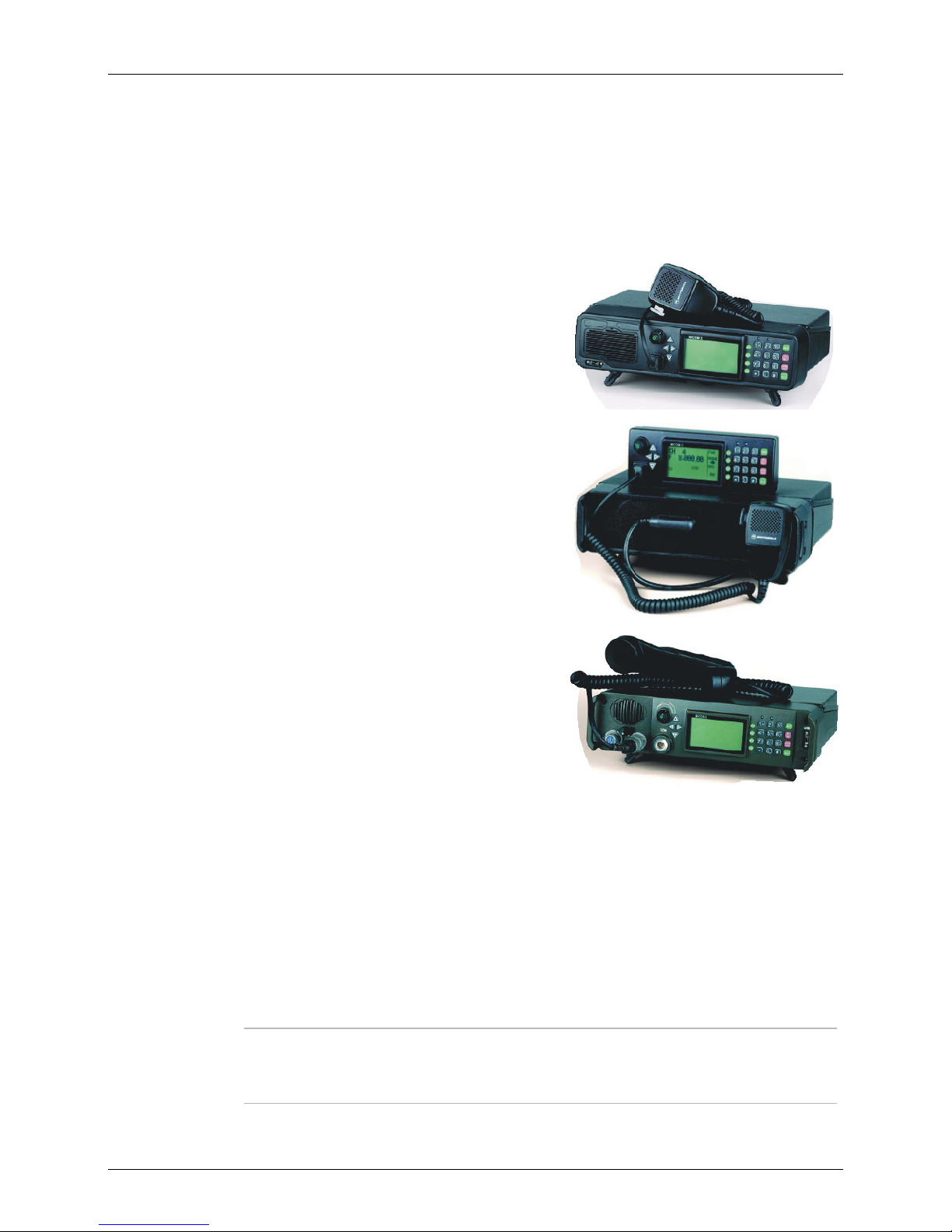
MICOM-3F
Transceiver for long range wireless voice, fax, data and
email communication, with built-in front panel, for fixed
and mobile use.
MICOM-3T
Transceiver for trunk mounting with separate control box,
saves valuable cabin space in mobile use.
MICOM-3R
Ruggedized transceiver with military handset and
connectors, for fixed and mobile use in applications
requiring the utmost dependability and reliability.
In Appendix A, you will also find information on the micomTrooper 3, the 5-to-50W backpack
transceiver version of MICOM-3 transceiver, and its Battery Charger, FLN9541.
For convenience, the manual is divided into two Parts:
• Part I – Operation and Installation (this Part) presents the information you need to familiarize
with MICOM-3 radios and operate them efficiently. It also explains how to install your radio set
and correct most of the problems that may occur during its operation.
• Part II – Manual Programming explains in detail how to program manually any radio parameter
from the MICOM-3 front panel, instead of using the dedicated MICOM-3 Radio Control
Application (MRC) or Radio Service Software (RSS). For this purpose, you will find in this Part
explanations and step-by-step instructions that expand the general radio programming of Part I.
Note
In both Parts of this manual, the generic term MICOM-3 is used for information
applicable to all the transceiver versions. The complete transceiver designation is
used only for information applicable to a specific equipment version.
1

MICOM-3F/3T/3R HF-SSB Owner’s Guide
MICOM-3 HF-SSB Radio Features
• Digital Signal Processing (DSP)
• Built-in Test Equipment (BITE)
• RF power indications
• 200 channel capacity, simplex or half-duplex
• Channel scan or Automatic Link Establishment (ALE) per MIL-STD-188-141B/FED-STD-1045
• MultiNet function for seamless integration of different HF radio networks in one network
• Automatic IF shift
• Clarifier
• Voice-activated digital squelch
• Excellent transmitter and receiver performance
• High frequency stability option
• DSP software can be upgraded to incorporate future options and new technologies
• Large LCD display and optional support for multiple languages
• MIL-STD-810C, D and E compliance.
Transmitter Features
The maximum output power of the transmitter is 125 W PEP (Peak Envelope Power). The average
transmission duty cycle is up to 1:4, thus enabling even CW (Continuous Wave) signals to be
transmitted at the maximum available power. Output power can be preprogrammed to one of four
levels: 25W, 62.5W, 100W and 125W. Accurate sensors are used to keep the output power at the
selected value.
The transmitter includes thermal protection. If, for any reason, the transmitter internal temperature
exceeds the maximum permitted temperature, the output power is automatically reduced to avoid
any fault due to excessive heat. Antenna mismatch protection is also included. If the VSWR (Voltage
Standing Wave Ratio) rises to more than 2:1, the transmission will be inhibited to avoid damage and
a message will be displayed.
Receiver Features
The radio utilizes digital signal processing for implementing most of the receiver functions, e.g.,
demodulation, narrow band filtering, automatic gain control, noise blanking, tunable notch filter,
squelch, etc. An automatic digital noise blanker is activated whenever repetitive noise (e.g., ignition
spikes) is encountered in the received signal. The digital syllabic (speech identifier) squelch is
activated whenever speech is identified, thus opening the audio path. However, if speech is not
received, the audio path is muted, thus preventing background noise from disturbing the operator.
Frequency Sources
Two types of frequency sources are available for the MICOM-3 radio. The standard 0.6 ppm DTCXO
frequency source which assures a frequency accuracy of better than ±18 Hz. For frequencies lower
than 10 MHz, it assures a frequency accuracy of better than ±6 Hz. When higher frequency accuracy
is required, the G112 0.1 ppm OCXO frequency source can be ordered. It will assure a frequency
accuracy of better than ±3 Hz at 30 MHz.
2

Introduction
Power Source
The radio is designed for 13.8 V ±20% negative-ground operation and may be connected to a
standard 12 V battery.
CW Keying Operation
When the CW key is pressed, the radio transmits a continuous wave (at the full programmed power)
and stops transmission when the key is released. CW keying operation is enabled by connecting a
Morse key to the accessories connector. If you wish to operate CW keying with external headphones,
the S809 Interface cable can be used, thus enabling a standard PL55 headphone and standard PL99
Morse key to be connected to the accessories connector.
Programmable Features
The radio can be programmed using a PC running the MICOM Radio Control Application (MRC) or
the Radio Service Software (RSS). The following radio features can be programmed:
• Up to 200 simplex/half duplex channels supporting SSB (J3E), AME (H3E), or Pilot (R3E) modes.
• Up to four levels of output power (up to 125W PEP and average).
• Five scanning groups of up to 200 channels, each with guard channel.
For further details, refer to “MICOM Radio Control Application Owner’s Guide”, Publication
6886869J01, or to “MICOM-3 HF-SSB Transceiver, RSS User’s Guide”, Publication 6886867J01.
MICOM-3 Options and Accessories
• RS-232 remote control interface
• Linear power amplifier interface
• Phone patch interface
• Data/fax modem interface
• MRC or RSS for PC
• High (0.1 ppm) frequency accuracy
• micomLink
• VP-116 voice privacy unit
• HF vocoder unit
• Internal GPS receiver
• ISB operation
• Desktop microphone
• Automatic antenna tuners
• Continuous duty data transmission kit
• AC power supply
• 500 W linear power amplifier
• 1 kW linear power amplifier
• Antennas and grounding
• CW key and headphones
• External speaker.
3
MICOM-3F/3T/3R HF-SSB Owner’s Guide
Familiarization with MICOM-3 Radios
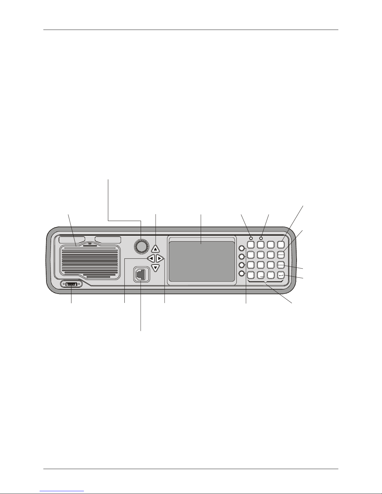
MICOM-3F Front Panel
ON/OFF & Volume Control
Turns radio on and off
and controls the
speaker volume
Internal Speaker
Connector for
Optional
External USB
Keyboard
Up/Down Keys
Used to scroll
values
Move
cursor to
the left
Microphone
Connector
Connector for
microphone
with PTT and
cable to RSS
Display
MICOM -3
MORE Key
Displays additional
menu options when
appear in the display.
Û
Also serves to move
the cursor to the right
Not used
?
@
1
23
/
F1
G
H
4
56
I
F2
P
R
F3
Q
89
7
S
F4
0
*
Function Keys
Activate different
functions, as
displayed next
to each key
Tx Indicator
Lights when
radio is
transmitting
A
D
B
E
MENU
C
F
M
J
LO
T
V
P
N
K
Esc
Y
ALARM
W
U
X
GPS
Z
#
Keypad
A set of keys
used to enter
alphanumeric
data
MENU Key
Displays the
main menu
ESC Key
Cancels the
last action
and reverts to
the previous
screen
Not used
ENTER Key
Saves the
selection
and/or value
4
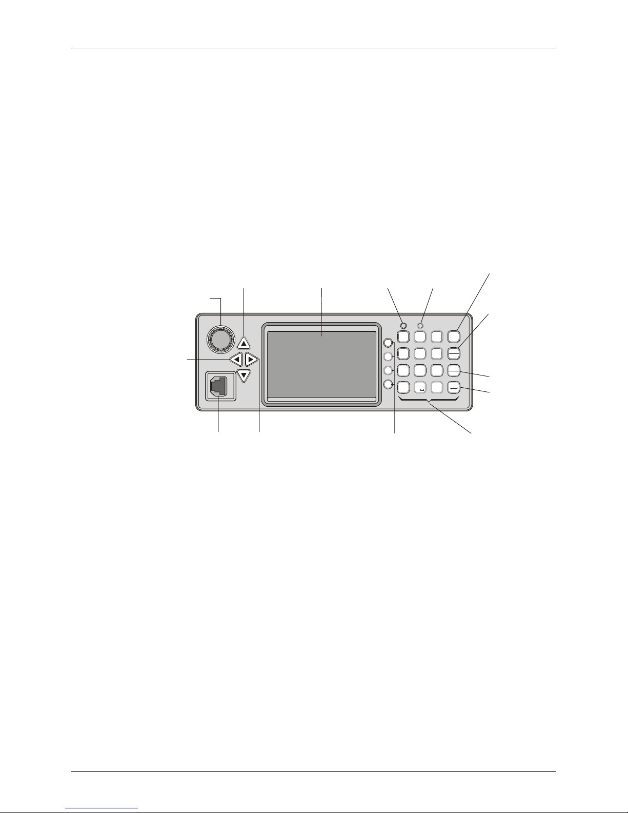
MICOM-3T Front Panel
Familiarization with MICOM-3 Radios
ON/OFF & Volume Control
Turns radio on and off
and controls the
speaker volume
Move
cursor to
the left
Microphone
Connector
Connector for
microphone
with PTT and
cable to RSS
Up/Down Keys
Used to scroll
values
MICOM-3
MORE Key
Displays additional
menu options when
appear in the display.
Û
Also serves to move
the cursor to the right
Display
Not used
?
@
23
1
/
F1
G
H
4
5
I
F2
P
R
F3
Q
89
7
S
F4
0
*
Function Keys
Activate different
functions, as
displayed next
to each key
Tx Indicator
Lights when
radio is
transmitting
A
D
B
MENU
E
C
F
M
J
L
T
V
KN
6
O
Y
W
U
X
Z
ALARM
P
Esc
GPS
#
Keypad
A set of keys
used to enter
alphanumeric
data
MENU Key
Displays the
main menu
ESC Key
Cancels the
last action
and reverts to
the previous
screen
Not used
ENTER Key
Saves the
selection
and/or value
5
MICOM-3F/3T/3R HF-SSB Owner’s Guide
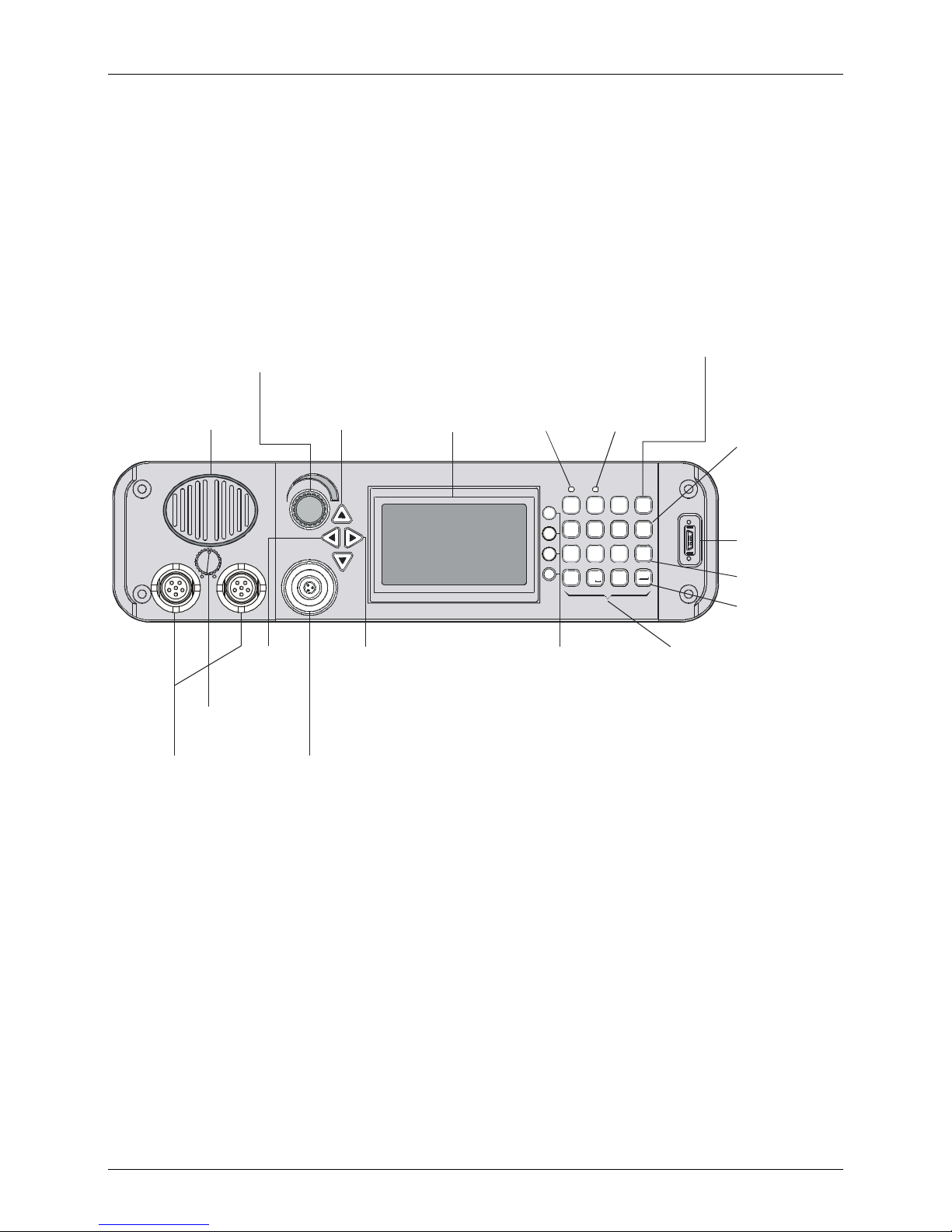
MICOM-3R Front Panel
ON/OFF & Volume Control
Turns radio on and off
and controls the
speaker volume
Internal Speaker
AUDIO
Internal Speaker
ON/OFF Switch
Audio
Connectors
Connectors for
external speaker
and handset
Up/Down Keys
Used to scroll
values
COM
Move
cursor to
the left
Microphone
Connector
Connector for
microphone
with PTT and
cable to RSS
Display
MICOM-3
MORE Key
Displays additional
menu options when
appear in the display.
Û
Also serves to move
the cursor to the right
Tx Indicator
Lights when
radio is
Not used
1
F1
4
F2
F3
7
F4
transmitting
A
?
@
BE
23
/
C
J
G
K
H
56
LO
I
P
T
R
U
Q
89
V
S
0
*
Function Keys
Activate different
functions, as
displayed next
to each key
D
F
M
N
Y
W
X
Z
#
MENU Key
Displays the
main menu
MENU
P
Esc
ALARM
GPS
Keypad
A set of keys
used to enter
alphanumeric
data
USB
ESC Key
Cancels the
last action
and reverts to
the previous
screen
Connector
for
Optional
External USB
Keyboard
Not used
ENTER Key
Saves the
selection
and/or value
6
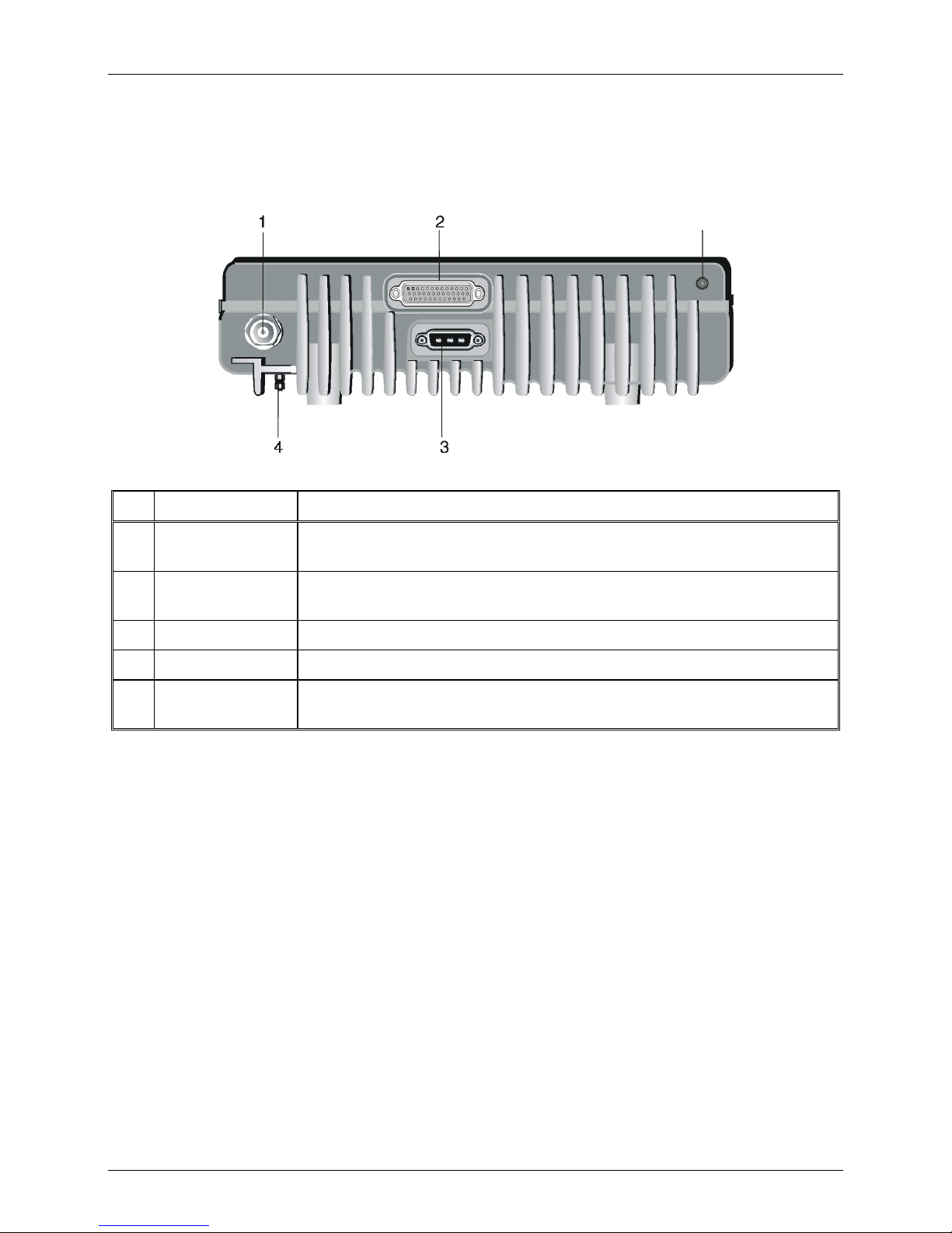
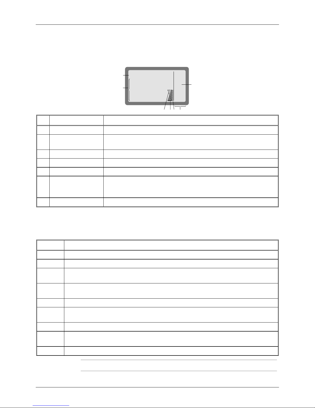
Rear Panel (All Models)
No. Item Function
Familiarization with MICOM-3 Radios
5
1 Antenna connector N-type female connector for connection to antenna or optional linear power
amplifier
2 Accessories
connector
3 DC connector 3-pin D-type male connector for connection of DC power source
4 Grounding screw Connection of ground to the radio case
5 GPS antenna
connector
44-pin male D-type connector, used to connect the radio to external accessories
such as: personal computers, MRC, external modems, Morse key, etc.
Connection to the GPS antenna (for MICOM-3 with the optional GPS receiver)
7
MICOM-3F/3T/3R HF-SSB Owner’s Guide
6
LCD Display Functions
Display Organization
MICOM-3
1
CH 6
F 16,000.00
2
SQ BW3.3
AGC
No. Designation Description
1 Mode indicator Indicates the current working mode
2 Work area Displays information on the current working mode and the selected operating
parameters
3 Transmit level indicator In the transmit mode, displays the relative transmitter power
4 Receive level indicator In the receive mode, displays the relative power of the received signal
NF
USB
NB
CLAR
PWR
MODE
I
AGC
BW
53 4
7
5 Tx Bar Appears when the radio is transmitting
6 More options icon The presence of this icon indicates that more options can be displayed in the
options area. Press the
key when this icon appears to see more menu
MORE
options
7 Options display area Displays a list of options you can select in the current working mode
Other Indications
The following indications may appear in the work area of the LCD display to indicate functions that
are active when you work with MICOM-3.
Indication Meaning
USB
LSB
SQ
MON
AGC
BW
Using upper sideband for transmission and reception
Using lower sideband for transmission and reception
Squelch is active: the speaker is turned on only when the radio identifies speech, to prevent
reception noise from being heard (see Note)
When using ALE, indicates that the speaker is normally off, and is automatically turned on when
the link is established (see Note)
Non-standard AGC mode (AGC off, or fast AGC) has been selected
Non-standard bandwidth has been selected (the bandwidth appears next to the BW indicator for
example, 3.3 (3.3 kHz) in the display shown above)
NB Noise blanker is active
CLAR
NF
8
Clarifier is active (meaning that you selected a frequency deviating from the nominal channel
frequency)
Notch filter is active
Note
For the MICOM-3R, the squelch and monitor functions also effect the handset.
Familiarization with MICOM-3 Radios
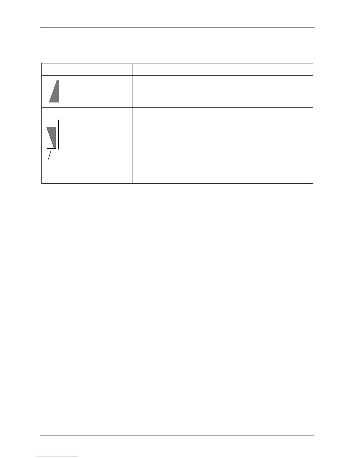
RF Level Indications
Indication Meaning
Strong received signal
Reflected
Power
Weak received signal
Full transmit power
(125W)
Actual transmit power
Low transmit power
Relative indication of received RF signal, displayed when the radio is in
the receive mode
Transmit bar appears when the radio is switched to the transmit mode
(for example, when the PTT is pressed). Its length indicates the MICOM3 maximum transmit power, 125 W.
The height of the inverted triangle indicates the relative transmitter
output (forward) power. It fluctuates as a result of modulation.
The relative reflected power is indicated by the base line: its length
indicates the fraction of power reflected because of antenna VSWR (the
length should be small relative to the total height of the indicator, which
is proportional to the forward power)
Audible Indications
The user can configure the MICOM-3 to generate audible tones to indicate events related to the
radio operating conditions. The tone volume, low or high, may also be set using the RSS, MRC or by
programming from the front panel.
Event Description
Valid key pressing Beep sounds when a key is pressed, to indicate that the key pressing has been
accepted. No beep – no action.
PTT release A beep sounds on the remote radio to indicate that the local PTT button has
been released.
ALE alerts During ALE operation, beeps alert you to events you should be aware off, e.g.,
link establishment/disconnection etc.
9
MICOM-3F/3T/3R HF-SSB Owner’s Guide
General Procedures
This section provides general procedures that will help you start using your MICOM-3 radio and get
the most of its advanced features.
Most of the activities that can be performed by you (selection of operating mode, status display,
programming, testing, etc.) are done using the keypad together with the four navigation keys (up, down,
left and right) and the front panel display.
To simplify operation, MICOM-3 uses soft keys that let you control the radio simply and efficiently,
using a menu-driven mode that guides you and helps you make the required selections.
“Menu-driven” simply means that whenever you must select a parameter, an operating mode, etc.,
you select it from a list of allowed values displayed on the front panel display, thereby reducing the
chance of error:
• To make the selection, you use navigation keys to reach the desired parameter value or
operation, and then confirm the selection by pressing the ENTER key.
• To let you go back to previous options, there is an ESC key.
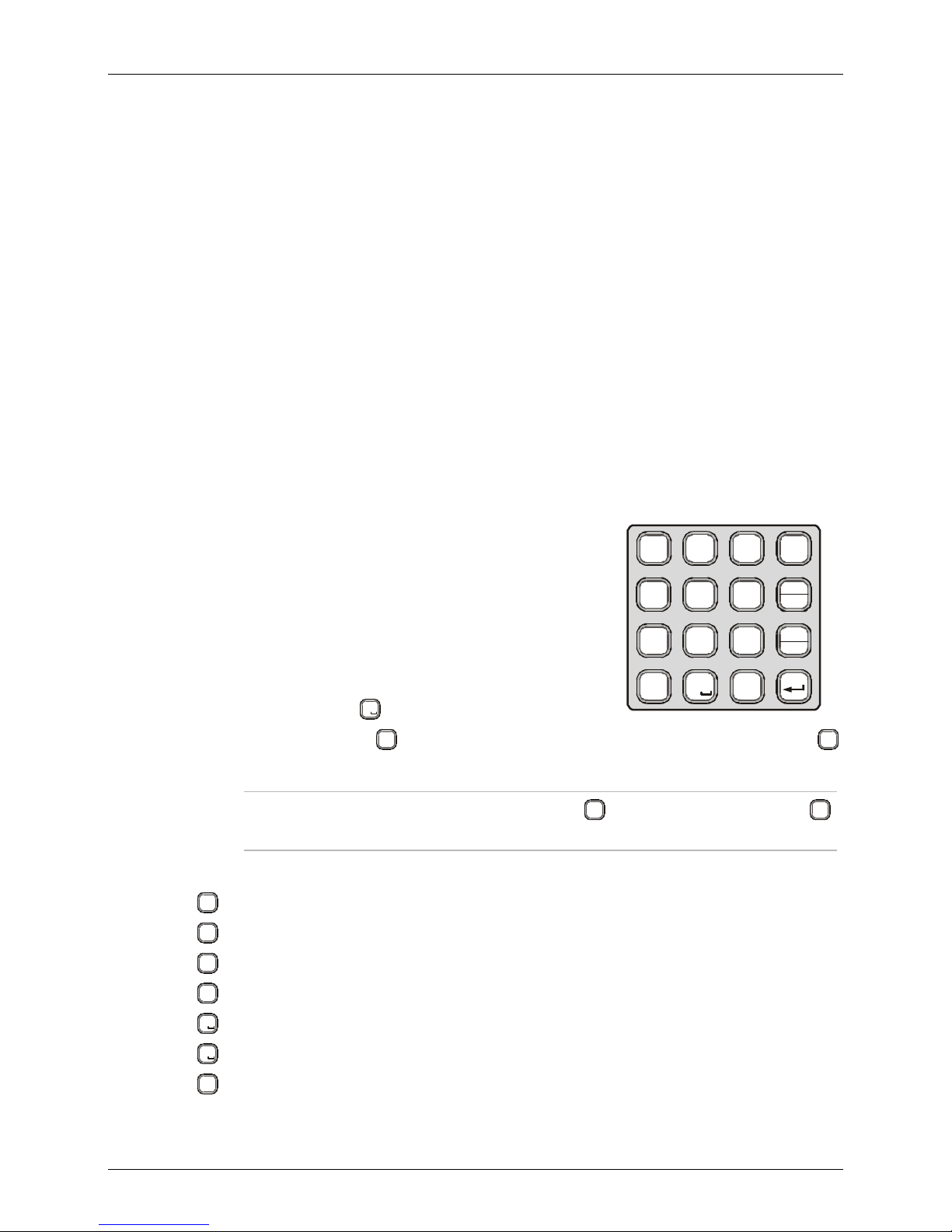
Using the Keypad
Each key is imprinted with a numeral and several letters. These
characters are accessed in clockwise order, as follows:
• A single key press enters the numeral
• Two consecutive key presses enter the first letter
?
@
1
/
G
4
I
AD
23
CF
JM
H
56
LO
BE
K
MENU
N
P
Esc
• Three consecutive key presses enter the second letter
• Four consecutive key presses enter the third letter.
• Five consecutive key presses enter the fourth letter.
0
• To enter a blank space, press
When entering frequencies, use the
twice.
key as a decimal point, if needed. In the ALE mode, the *
*
key is also used to enter the wild-card character (? or @).
Note
To enter the ampersand @ symbol, press the
key.
Example: to enter “MIKE 01”:
M
N
Press
Press
Press
Press
Press
Press
Press
twice (for the letter M).
6
O
G
H
4
four times (for the letter I).
I
J
K
5
three times (for the letter K).
L
D
E
3
three times (for the letter E).
F
0
twice (for the blank space).
0
once (for the numeral 0).
?
@
1
once (for the numeral 1).
/
P
R
Q
7
89
S
0
*
key twice. Do not use the
#
Y
T
U
V
Z
#
ALARM
W
X
GPS
?
@
1
/
10
Familiarization with MICOM-3 Radios
Function Keys
The function keys F1, F2, F3 and F4 appearing next to the display
are soft keys used to select options which depend on the current
radio mode. The current function of each key is shown in the
options area of the display, next to the key. For example, on the
MICOM-3
PROG
PROG screen you can press F2 to start programming the ALE
parameters.
If a certain function key is not used, no label appears next to the
key (see for example F4), and pressing that key has no effect.
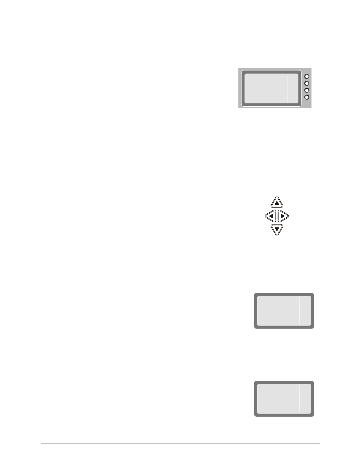
Scroll (MORE) Key
The MORE key is used to scroll the options appearing in the options area of the display.
Up/Down Scroll Keys
The up and down scroll keys are used to scroll between values that are
already programmed into the radio. For example:
• In the Channel mode, pressing the up or down scroll key once lets
you view the previous, respectively next, programmed channel.
Pressing either key continuously scrolls the channels in the selected
direction.
Up
RAD
ALE
LANG
More
F1
F2
F3
F4
• In the Frequency mode, you can change the frequency in the
corresponding direction.
• In the radio Programming mode, you can use these keys to scroll
among the programmable parameters.
Selection from List of Predetermined Values
When the parameter you want to select can assume only one of several
predetermined values, you select the desired value by pressing the
function keys:
• F1 enters the lowest possible value (or OFF)
• F4 enters the highest possible value
• F2 and F3 increment or decrement the value. When you reach either
end, the corresponding key disappears
You cannot use the keypad to enter a value for such parameters.
Toggle Mode
When the function being set can only be toggled on or off, one function
key will be marked YES and another NO.
To expedite turning on and off often-used functions (for example, turn the
squelch on or off) only one key is used. In this case, just press the key
assigned to the function to be toggled: the new state is shown for a few
seconds, and then disappears as it takes effect immediately.
Down
MICOM-3
PROG
ADT - 9 SEC
MICOM-3
PROG
ALE - NO
1
<--
-->
10
YES
NO
11

MICOM-3F/3T/3R HF-SSB Owner’s Guide
Alphanumeric Edit Mode
When you need to enter an alphanumeric string in a field, or edit a string, you type the desired
alphanumeric character on the keypad. A blinking cursor _ indicates the location being edited.
In addition, the following function keys are available:
SAVE (F1) Saves editing changes (equivalent to pressing the ENTER key).
<−− (F2)
−−> (F3)
Used to move the cursor backwards and forwards. When you reach either end,
the corresponding key disappears.
CLR (F4) Pressing this key momentarily erases the digit/letter at which the cursor is
presently located, and shifts the entire field one place to the left.
Press this key continuously clears the entire field.
Numeric Edit Mode
When you need to enter a number in a field, or edit the number, you type the desired digits on the
keypad. A blinking cursor _ indicates the location being edited.
In addition, the following function keys are available:
BACK (F3) Erases the last digit.
CLR (F4) Erases all newly entered digits and restores the original value.
View Mode
When the string to be displayed is longer than the number of characters that fit in one line (for
instance, with long addresses or messages), the view mode enables scrolling to the rest of the string.
The view mode is indicated by the symbol <-> next to one of the
function keys.
When you press <->, the key functions change:
HOME (F1) Scrolls to display the first character of the string.
<−− (F2)
−−> (F3)
Scroll one character to the left or right, respectively. If
you press either key continuously, the scrolling continues
at a rate of four characters per second.
END (F4) Scrolls to display the last character of the string.
MICOM-3
AMD 0
AMD MESS
01
MICOM-3
AMD 0
1
AMD MESSA
EDIT
ERAS
<->
HOME
<--
-->
END
When you reach the beginning of the string, the HOME (F1) and <−− (F2) function keys disappear,
whereas when you reach the end of the string, the −−> (F3) and END (F4) function keys disappear.
Message Attached Alert
When a message is attached to the received call (an option available for
ALE calls, even if you are using the Channel mode), an exclamation sign !
appears to the left of the originating station name.
You can view the message contents after you accept the call.
12
MICOM-3
FROM
!ABC
 Loading...