


®
L
t
Programmable differential pressure transmitter
for pressure or flow measurement and control
with purging function for flow sensors.
NOTE !
Read the entire instruction carefully before start.
Application
MicaFlex PFTT is a pressure and flow transmitter
with built in PI-controller and a temperature input
which makes it possible to compensate flow mea
surement for temperature changes.
MF-PFTT can be programmed to activate a purging
unit, MF-PU-2, for automatic cleaning of flow sen
sors with compressed air on set intervals.
With the four key pad, ¹, ¸, PGM and ESC
sired function is selected as well as setting and scal
ing is done. The dual row LCD display clearly indi
cates the selected function.
Installation
MF-PFTT is designed to be placed on a wall or for
recessed mounting through a wall or cabin door.
When recessed mounting, a mounting kit,
MFM-PANEL is used. The unit is fixed to the wall by
four screws, max 4 mm. The location of the holes is
shown at the back of the enclosure.
Unscrew the four screws of the front cover and use
the bottom screws to attach the front cover on the
upper end of the casing, see Fig 2. This makes installation and electrical connection easier.
Connect power supply according to the electrical
connection.
To each front cover the CPU is mounted, since the
I/O calibration of the main circuit board is stored on
the CPU-board, it is not possible to move the front
cover between different units.
© AB MICATRONE 2009-02-12 [H:\ Apps \ Typeset \ Mima \ Mi-261gb_090212.vp]
Output signal
MF-PFTT has two analogue outputs to be used for
actual value of pressure and flow, temperature,
purging unit or PI-control output for pressure or flow.
VDC or mA output signal must be set by the
DIL-switch (DIL1). The same programming must
then also be done under “Outputs”.
, the de
-
-
-
-
-
Use the front cover bottom screws (marked A)tofixthefront
Basic programming instruction
When the power supply is connected a start menu
will be displayed. With ¹¸ it is possible to scroll
through the different start menus. To always have
the same start menu, the selection is programmed
under “System settings”. Pressing ESC when some
other menu is displayed returns to the menu programmed under “Display”.
Programming
Press PGM until "PROGRAM-MENU" appears. Re
lease the key and the display shows parameter
group, see table on page 2.
With ¹¸ it is possible to scroll through the parame
ter groups.
1. Current values
2. System settings
3. Outputs
4. Pressure
5. Flow
Operating and installation manual
MF-PFTT
Instruction : mi-261gb_090212
A
cover at the enclosures top edge during installation.
A
Fig 2
-
-
PL1
J5
D1
3
ON
12345
DIL1
N-
L+
DIL 1: 1 on, 2 off volt output 1
N-
OutOu
3 on, 4 off volt output 2
1 off, 2 on mA output 1
3 off, 4 on mA output 2
Output/Utsignal
Fig 1
1
2
6. Temperature
7. PI2 controller
8. Purging unit
9. Communication
10. Internals
When the parameter group to be programmed is
shown, press PGM. The parameters are then
shown, with ¹¸ select the parameter to be pro
grammed and press PGM.
-

Par.no: Parameter Range Value
Internals
0 Prog ver 0.00...9.99
Current values
100 dP -32768...32767
101 Flow -32768...32767
102 PI2 0.00...100.00
103 PI2 CSP -32768...32767
109 Temp -3276,8...3276,7
110 Purging OFF
PRE
CLEAN
POST
PAUSE
TEST
System settings
4 Display dP
FLOW
dP+FLOW
dP+PI2
FLOW+PI2
dP+TEMP
FLW+TEMP
5 Damping[s] 0...9
(hidden) Access code 0...9999
Outputs
19 Output 1 dP
FLOW
PI2
TEMP
CLEAN
20 Signal 1 0..10V
2..10V
0..20mA
4..20mA
21 Output 2 dP
FLOW
PI2
TEMP
CLEAN
22 Signal 2 0..10V
2..10V
0..20mA
4..20mA
Pressure
23 MinCal[Pa] -32768...32767
24 MaxCal[Pa] -32768...32767
25 Unit dP Pa
PaDec
mbar
iwc
26 Min Range -32768...32767
27 Max Range -32768...32767
28 Min Output -32768...32767
29 Max Output -32768...32767
30 Sign dP POS
NEG
Flow
31 Unit flow L/s
m3/s
m3/h
m/s
cfm
32 Max flow 0...32767
Par.no: Parameter Range Value
33 Scale flw 0...32767
34 Set flow 0...32767
92 Compens OFF
ACTUAL
NORMAL 0
Temperature
93 Input OFF
0..10V
2..10V
0..20mA
4..20mA
Pt-100L
Pt-100H
Pt-1000L
Pt-1000H
94 Min Input -30...600
95 Max Input -30...600
PI2 Controller
35 Source OFF
dP
FLOW
36 Mode AUTO
HAND
37 Output DIRECT
REVERSE
52 Temp 1 -30...600
53 SP1 -32768...32767
54 Temp 2 -30...600
55 SP2 -32768...32767
56 SPC OFF
TEMP
39 NZ [%] 1...50
40 P-band 0...9999
41 I-time [s] 0...999
42 BZ [%] 0...100
43 I-time BZ 0...999
96 Min out 0,00...100,00
97 Max out 0,00...100,00
Purging unit
62 Mode OFF
ON
TEST
63 On Time [s] 0...99
64 Pause [s] 30...3600
Communication
47 Adress 1...247
48 Location 0...32767
49 Protocol Comli
50 BAUD 600 b
1200 b
2400 b
4800 b
9600 b
51 Protect NO
YES
© AB MICATRONE 2009-02-12 [H:\ Apps \ Typeset \ Mima \ Mi-261gb_090212.vp]
2

Scrolls start menus
in the opposite way
AB MICATRONE
dP
48,5Pa
AB MICATRONE
Flow
Flow
PI2
4,80m3/s
4,80m3/s
20,4%
dP
Flow
dP
PI2
48,5Pa
4,80m3/s
48,5Pa
15,9%
Flow/dP
Auto
(PGM)
Current values
System settings Outputs Pressure
Temperature
(PGM)
PI2 controler Purging unit
%
Press key until displayed text disappears.
Scrolls parameter group in the opposite way
Opens parameter group and allows the
parameters to be selected.
Flow/dP
Hand
%
Flow
Internals
Output %
Outputs
Output 1
Outputs
Signal 1
© AB MICATRONE 2009-02-12 [H:\ Apps \ Typeset \ Mima \ Mi-261gb_090212.vp]
Outputs
Output 2
Outputs
Signal 2
dP
0..10V
PI2
4..20mA
(PGM)
(PGM)
(ESC)
(ESC)
Changes between the parameters
according to the parameter list.
Programming position for Unit/Value (Flashes).
Selection of Unit/Value.
Programming of new value. Parameter Unit/Value is flashing.
When programming a number value, each digit is
programmed seperately, until all digits have stopped flashing.
Leaves parameters and returns to Parameter group.
Leaves the parameter group and returns to startmenu.
Always note the programmed data beside the parameter
in the programming protocol for future documentation
3

Digit programming
Every digit is separately programmed. Press ¸ for
1...9, after 9 if negative values are accepted -9...0.
Digit to be changed is flashing . When all digits are
programmed press PGM and the entire row will
flash. To stop incorrect programming press ESC
and then PGM to execute new programming.
Unit or value programming
Press ¹¸ to change unit/value. When selected
press PGM then the entire row will flash.
Press ESC to return to parameter group.
Press ESC to leave the parameter group and return
to start menu.
Cancel the current programming
It is always possible to stop an incorrect program
ming with ESC if you have not pressed PGM after
the last digit or unit/value selection.
Programming instruction
We recommend you to follow this instruction.
When any of the start menus is displayed press
PGM until "PROGRAM-MENU" appears. Then re
lease the PGM key.
1. Current values
100 dP -32768...32767
101 Flow -32768...32767
102 PI2 0.00...100.00
103 PI2 CSP -32768...32767
109 Temp -3276,8...3276,7
110 Purging OFF
PRE
CLEAN
POST
PAUSE
TEST
the program and function menu.
For units with built-in control function the code must
also be entered to switch between AUTO and
HAND operation.
Indication of the measured values and operating
state is accessible without entering the code.
At delivery the code is programmed to "0000" un
less nothing else is agreed to. With factory default
code "0000" the key lock is inactive. I.e no protec
tion for alternating the settings.
Activating the key lock
To activate the key lock settings must be pro
grammed into the parameter 'Access code' which is
found below the parameter group 'System settings'.
The code must be different from "0000" unless the
lock will be in-active. After programming a 4-digit
code into the parameter this code must be used to
access the program and function menus.
In-activating the key lock
The key lock can be in-activated by setting the value
of parameter 'Access code' to "0000". Since the set
ting is done from the program menu the already
programmed code must be known to inactivate the
key lock.
Contact Micatrone if the code has been lost!
Entering code
To access the program or function menu or to switch
between AUTO-HAND function the code must be
entered.
Example to access the program menu:
Press the PGM-key to open the program menu.
Keep the key pressed until following screen appears.
-
-
-
-
Shows the actual values and the state of the purg
ing function.
2. System settings
4 Display dP
FLOW
dP+FLOW
dP+PI2
FLOW+PI2
dP+TEMP
FLW+TEMP
5 Damping[s] 0...9
(hidden) Access code 0...9999
Select the start menu to be displayed.
Select the time constant (damping) for the flow and
pressure measurement 0...9 seconds, normally
1...3 seconds.
Key lock is a hidden parameter if the function is acti
vated and no code has been entered.
The key lock is to be used when transmitters set
tings must be protected from unwanted alteration.
The 4-digit code must be entered before accessing
-
MF-PFTT
PROGRAM-MENU
Release the PGM-key. If the key lock is activated
the following screen appears.
ENTER CODE: 0***
PROGRAM-MENU
The first digit (0) is flashing to indicate that the first
digit of the code must be entered by using the ar
row-keys. Press the PGM-key to jump to the second
digit, etc.
When all four digits are entered press a final time
the PGM-key. The entered code is now compared
-
-
© AB MICATRONE 2009-02-12 [H:\ Apps \ Typeset \ Mima \ Mi-261gb_090212.vp]
-
4

with the settings in the parameter 'Access code'. If
they match the program menu is accessed.
actual value for temperature measurement and
purging control (CLEAN).
Current values
The menu is accessible until the ESC-key is
pressed one or several times and the preset start
menu is displayed. Example:
AB MICATRONE
Flow 12.34 m3/s
If the code does not match the programmed settings
following screen appears
INVALID CODE
PROGRAM-MENU
for a period of 2 second before shifting to the "Enter
code" screen again.
ENTER CODE: 0***
PROGRAM-MENU
By pressing the ESC-key during the operations the
programming of the code is aborted and the preset
start menu is displayed.
NOTE ! There is only one controller in the unit. The
source for the PI-controller is programmed under
“PI2 controller”.
To measure and control flow or velocity it is neces
sary to connect the unit to a flow measurement de
vice mounted in the duct or fan inlet etc.
When controlling the purging function, the signal
output is 0 mA in OFF position and 20 mAin purging
condition. The output signal controls a relay inside
the purging unit, therefore the signal must be set to
mA-output and be programmed for 0...20mA.
Select the output signal for the two outputs, 0/2...10
VDC or 0/4...20 mA. You must also set the DILswitch on the circuit board for VDC or mA output.
It is possible to have VDC on one output and mA on
the other.
4. Pressure
23 MinCal[Pa] -32768...32767
24 MaxCal[Pa] -32768...32767
25 Unit dP Pa
PaDec
mbar
iwc
26 Min Range -32768...32767
27 Max Range -32768...32767
28 Min Out -32768...32767
29 Max Out -32768...32767
30 Sign dP POS
NEG
-
-
AB MICATRONE
Flow 12.34 m3/s
3. Outputs
© AB MICATRONE 2009-02-12 [H:\ Apps \ Typeset \ Mima \ Mi-261gb_090212.vp]
Select the sources for the two analogue outputs. The
selection is possible between actual value of pres
sure or flow, PI-control output for pressure or flow,
19 Output 1 dP
FLOW
PI2
TEMP
CLEAN
20 Signal 1 0..10V
2..10V
0..20mA
4..20mA
21 Output 2 dP
FLOW
PI2
TEMP
CLEAN
22 Signal 2 0..10V
2..10V
0..20mA
4..20mA
If the unit is used for flow measurement, you do not
need to do any programming under the parameter
group “Pressure”.
MF-PFTT is factory calibrated to a special range.
The range is marked on the label on the right side of
the casing. The calibration is always in Pa. Under
“Pressure” you also find the calibrated range, “Min
Cal” and “Max Cal”. These values are only notes
and are not possible to change.
If you want to change to another unit programme
“Unit dP”. Select Pa, Pa Dec (Pa with decimal),
mbar or iwc (inch water). When programming a new
unit the actual range is shown under “Min range”
and “Max range”. These values are only notes and
not possible to change. To change the range in se
lected unit or factory programmed unit, programme
“Min output” and “Max output”. The programmed
values shall always be in the selected unit (Pa,
Pa,dec, mbar, iwc). When scaling, note that the ac
curacy always is in % of the factory scaled range.
Sign for dP
When measuring a negative pressure normally the
MF-PFTT will show the same as measuring a positive
pressure (no sign). When programming “Sign dP” NEG
-
you get a negative (-) sign before the actual value.
-
-
5

5. Flow
31 Unit flow L/s
32 Max flow 0...32767
33 Scale flw 0...32767
34 Set flow 0...32767
92 Compens OFF
m3/s
m3/h
m/s
cfm
ACTUAL
NORMAL 0
If the unit isn´t to be used for flow measurement,
nothing has to be programmed under the parameter
group “Flow”.
3
Programme the unit for flow l/s, m
/s, m3/h, m/s or
cfm (cubic feet / minute).
The basic flow calculation used is made with ÖdP.
To have the display and the output corresponding to
the actual flow or velocity in the selected unit it is
necessary to make some calculations.
Different manufactors of flow measurement devices
have different calculation, but common for all is ÖdP.
Use the actual formula to calculate the max flow for
the factory calibrated measure range. The calculated flow or velocity at 20 °C is then programmed
under “Max flow” in the selected unit. The flow
range for max. output signal is programmed in
"Scale flw”, e.g. 3,5 m
3
/s = 10 VDC.
In parameter "Scale Flw", the flow should be entered at actual temperature or in normal flow if temperature compensation is activated. The output signal is linear compared to the flow or velocity.
NOTE ! If the range is not scaled, the same value in
parameter "Max flow" must also be programmed
into parameter "Scale flw". When scaling the flow,
note that the accuracy depends on the “Max flow”
range.
If adjustment of the displayed actual flow or velocity
must be done, it is possible to do under “Set flow”.
Programme the actual flow coming from a reference
flow sensor or equal.
NOTE ! The programming must be done at the
same time as the reference values are measured
(PGM-key is pressed).
Automatically the “Max flow” programming will be
changed for the new values. If the unit is connected
to a BMS system or equal, the “Max flow” or if
scaled, the “Scale flw” and the output signal must be
programmed in the connecting system.
With the parameter "Compens", the calculated flow
can automatically be compensated for changes in
the air density due to temperature changes. With
the parameter set to "ACTUAL" the flow is calcu
lated by the current temperature. With the parame
ter set to "NORMAL 0", the flow will be calculated as
if the temperature was 0 °C.
When the parameter is set to "ACTUAL", the letter
"A" is displayed in front of the selected flow unit, e.g.
Am3/s, and when set to "NORMAL 0", the letter "N"
is displayed in front of the selcted flow unit, e.g.
Nm3/h. This is to indicate that the the flow is calcu
lated for the current temperature or in normal flow.
6. Temperature
93 Input OFF
94 Min Input -30...600
95 Max Input -30...600
0..10V
2..10V
0..20mA
4..20mA
Pt-100L
Pt-100H
Pt-1000L
Pt-1000H
Within this parameter group, the temperature sen
sor input is selected. It is possible to use an ana
logue signal, 0/2...10 VDC or 0/4...20 mA, Pt-100 or
Pt-1000 sensor.
When using an analogue signal the signal must be
scaled in parameter "Min Input" and "Max Input".
Pt-100 and Pt-1000 has two measuring ranges, either low (L) or high (H).
The low selection has a temperature range of
-30...80 °C and the high selecting has a temperature range of 0...600 °C. The setting of parameters
"Min Input" and "Max Input" will automatically be set
for the low or the high range.
Change the setting of the DIL-switch located in the
upper right corner on the temperature input circuit
board, to correspond with the programmed settings,
VDC, mA, Pt-100 or Pt-1000. See figure on the last
page.
7. PI2 controller
35 Source OFF
36 Mode AUTO
37 Output DIRECT
52 Temp 1 -30...600
53 SP1 -32768...32767
54 Temp 2 -30...600
55 SP2 -32768...32767
56 SPC OFF
39 NZ [%] 1...50
40 P-band 0...9999
41 I-time [s] 0...999
-
-
42 BZ [%] 0...100
43 I-time BZ 0...999
96 Min out 0,00...100,00
97 Max out 0,00...100,00
dP
FLOW
HAND
REVERSE
TEMP
-
-
-
© AB MICATRONE 2009-02-12 [H:\ Apps \ Typeset \ Mima \ Mi-261gb_090212.vp]
6

If the PI-controller is not used, you do not need to do
any programming under the parameter group
“PI-controller”.
MF-PFTT has a PI-controller specially made for
pressure and flow control. The controller has two
programmable integral times.
The controller could be programmed as a standard
PI-controller, but in most of the applications to
gether with pressure and flow control we recom
mend to program it as an integral controller without
P-band. There are two programmable I-times.
Outside a desired limit on both sides of the set point
it is possible to have a shorter I-time and inside the
limits a longer I-time.
Programming
Select source: dP, FLOW or OFF.
Select mode: AUTO or HAND, Normally AUTO.
Select output to be: DIRECT or REVERSE.
Normally reverse (if the pressure or flow is higher
than the set point the output signal will decrease).
Programme the set point "SP1" in the earlier pro
grammed unit for dP or Flow.
Allowed limits are:
dP Pressure/Min Out .. Pressure/Max Out.
FLOW 0 .. Flow/Scale flw.
With the parameter "SPC", the set value can be
compensated for temperature changes. Select
"TEMP" to automatically have the unit to change the
set value between two different linear values.
DP/Flow
BZ
NZ
Setpoint
NZ
BZ
1
I-time
I-time BZ
I-time
2
-
-
I-time, Itime BZ, BZ and NZ
Fig 3
Min out & Max out
The output signal from the PI-controller kan be lim
ited within a specified range. The range is pro
grammed in percent into parameter "Min out" and
"Max out".
Example: If "Min out" is set to 30,00 and "Max out" is
set to 75,00, the output signal will be limited to
3,00...7,50 V (with 0...10 V setting) or 8,8...16,0 mA
(with 4...20 mA setting).
Hand position
Return to start menu and select the menu displaying
the PI-controller together with either the pressure or
flow value.
“Flow / dP”
“Auto 50.00 % “
Press PGM, “Auto” will shift to “Hand” and make it
possible to set the output in % with ¹¸ .
To return to “Auto” press PGM.
To return to start menu press ESC.
sec.
-
-
Selecting "Temp 1" will use "SP1" as the set value.
Selecting "Temp 2" will use "SP2" as the set value.
Current set point value can be read in parameter
group "Current values" and parameter "PI2 CSP".
Programme the neutral zone NZ 1...50 % of the se
lected pressure or flow range, normally 1...5%. The
NZ is in % of the scaled pressure or flow range with
half of the neutral zone on each side of the set point.
P-band
Normally not used for pressure and flow control.
© AB MICATRONE 2009-02-12 [H:\ Apps \ Typeset \ Mima \ Mi-261gb_090212.vp]
I-time
When programming as an I-controller there are two
possibilities.
1. The same I-time over the whole range. Nor
mally used. Program BZ = 000 and I-time BZ
= 000. The I-time should normally be longer
than the time for the dampermotor etc to go
frommintomax.
2. Shifting between two I-times. The reason for
working with two I-times is often that outside a
set pressure or flow limit you want to have a
fast response and inside a slow response (see
Fig 3). BZ: limit for switching I-time.
BZ is in % of the scaled pressure or flow
range. Half the Bz is on each side of the set
point. If the control output is not entering a
stable position, increase the I-time, you could
also try to increase the neutral zone.
8. Purging unit
62 Mode OFF
-
63 On Time [s] 0...99
64 Pause [s] 30...3600
ON
TEST
The purging function can be programmed in three
different states, OFF, ON or TEST -mode. "OFF" will
result in a inactivated mode. In "ON" mode the purg
ing function is activated and cleaning will be per
formed with even intervals. If the parameter is set to
"TEST", the purging function is active and will per
form constantly. This is used to check the purging
-
function.
In parameter "On Time" it is possible to set the time
for each interval to be during purging. The time is
programmed in seconds. Parameter "Pause" is
used to set the time between each purging. This pa
rameter is also programmed in seconds, 3600 sec
onds = 1 hour.
During the pause, the LED "Normal" is lit. Measure
ment and control are in operation. Two seconds be
fore the purging begin, the LED "Normal" goes out
and the measurement is stopped with the latest
read value stored and the control output signal is
frozen at the current level. When the purging begin,
-
-
-
-
-
-
-
7
the LED "Clean" is lit and the purging control signal
to the purging unit is activated.
After completed purging interval, the LED "Clean"
goes out and after an additional 5 seconds the mea
surement and control output is restored. The LED
"Normal" is lit and a new "Pause" time begin.
Technical Data
Indicator: Alphanumeric LCD
2 rows, 2 x 16 characters
Pressure range: see label on the unit
Flow ranges: l/s: 0...32767
3
/s: 0...327,67
m
3
/s: 0...32767
m
m/s: 0...327,67
cfm: 0...32767
Accuracy : < ± 0,5 % of pressure range
Temperature drift: < ±0,5 % /10 °C
Time delay: 0...9 sec.
Temp. input: Sensor Pt-100, Pt-1000 and
0/2..10 VDC, 0/4..20 mA
Outputs: Two analogue outputs
0/2...10 VDC, 0/4...20 mA
selectable and scaleable
Ambient temp: 0...50 °C'
Power supply: 24 VAC ±15 %
20...32 VDC
Power
consumption: 3 VA
Housing class.: IP 65
Electric connections
-rigid wire
-flexible wire
1x2,5mm
1x1,5mm
2
/ terminal
2
/ terminal
Cable entry: 2 x M16x1.5mm
(cable glands not included)
Dimensions WxHxD: 122 x 120 x 90mm
Conformity:
-EMC
-LVD
SS-EN 50081-1
SS-EN 50082-2
SS-EN 610101-1
Maintenance
Check the zero point every 6:th month.
Zero setting of the pressure transmitter
Disconnect the pressure tubes or set the manifold
valve in the calibration position.
With the startmenu displayed, press simultanously
both the keys ¹¸ until the display shows:
ZERO OFFSET
Release the keys when the display shows:
ZERO OFFSET
ADJUSTING
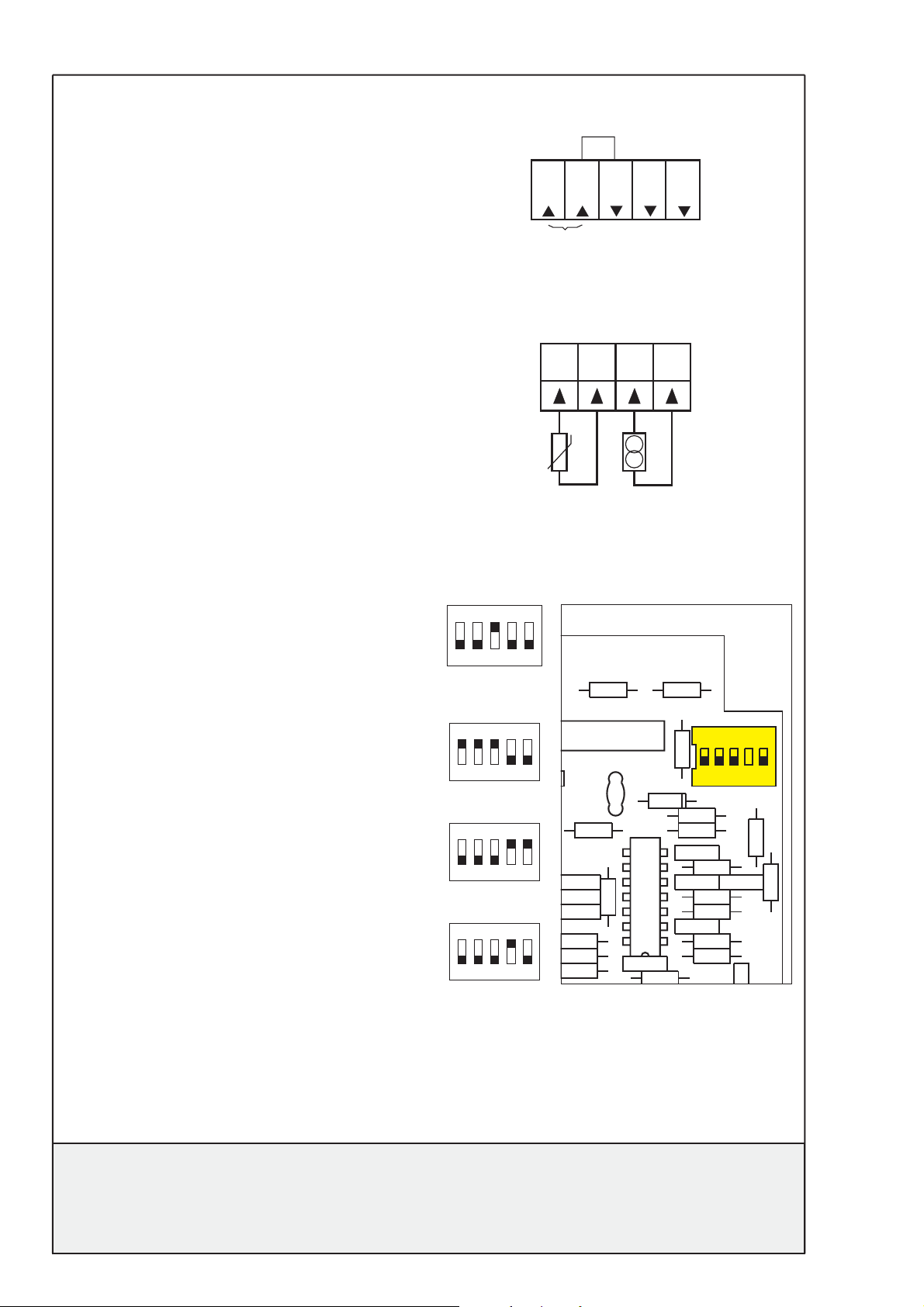
Electrical connection:
-
LN-N-
24 VAC
20...32 VDC
11 12
13
Out 1
Out 2
14
+
Pt-100
Pt-1000
Input type for temperature sensor
DIL-switch located in top right corner on PCB.
Volt:
ON
2345
1
0
mA:
ON
1
2345
Pt-100:
ON
1
2345
Pt-1000:
ON
2345
1
E4
R17
2
C5
R22
R16
R23
IC1
R21
mA
Volt
R7
R24
R25
D1
R26
DIL1
C10
AC1
ON
ON
12345
12345
C9
R6
C12
R10
R3
C1
R11
R19
R1
R5
© AB MICATRONE 2009-02-12 [H:\ Apps \ Typeset \ Mima \ Mi-261gb_090212.vp]
R13
When zero set is ready, the unit displays
ZERO OFFSET DONE
and automatically returns to start menu.
AB Micatrone Telephone: +46 8-470 25 00
Åldermansvägen 3 Fax: +46 8-470 25 99
SE-171 48 SOLNA Internet: www.micatrone.se
SWEDEN E-mail: info@micatrone.se
8
web reference - http://www.micatrone.se/prod_detail.php?lang=gb&id=53
 Loading...