

Page 1
MF-PFT
ver 3.x
Micafl ex PFT ver 3.
Pressure- and Flow transmitter with
control output
[© AB Micatrone, mi-302gb_171025] Page 1 of 8
Installation- & Operation manual
[Doc.id: mi-302gb_171025]
NOTE !
Read through the entire manual before you begin
installation and programming.
APPLICATION
MF-PFT is a microprocessor controlled transmitter/
controller for measurement and control of differential
pressure or fl ow. With the four keys on the front panel
it is possible to access all functions, make settings
and scaling the output signal. The double row, 2x16
character, LCD with backlight displays functions and
values.
MOUNTING
MF-PFT is designed for wall mounting but can be
fi tted with an optional frame kit, MFM-PANEL, for
recessed mounting on wall or through a cabinet door.
MF-PFT is screwed to the wall using four screws, max
ø 4mm. Location of screw holes are shown on the
backside of the enclosure.
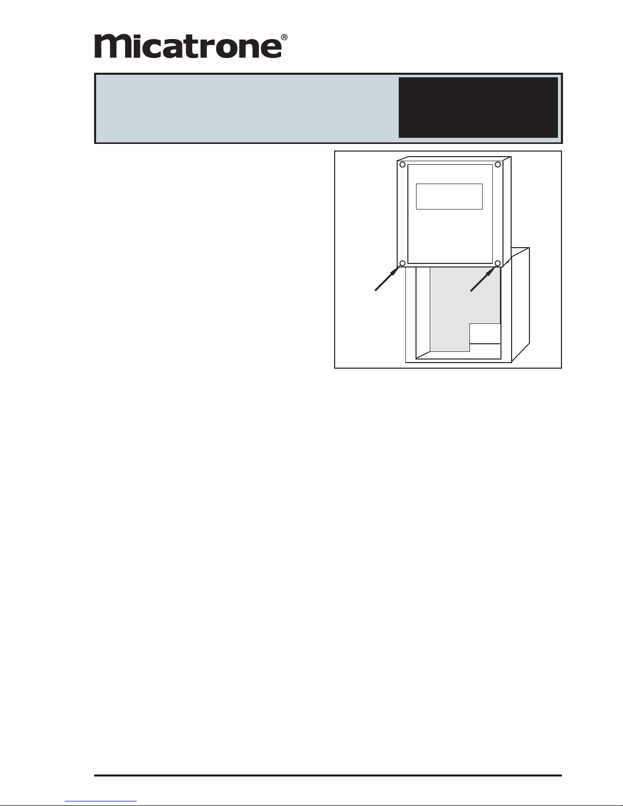
Unscrew the lid and use the bottom screws to
temporarily fi x the lid on the upper edge of the
enclosure during installation. See fi gure.
OUTPUT SIGNAL
MF-PFT has two analogue output signals which can be
used for pressure, fl ow or control signal. Each output
has three terminals, one for Volt DC, one for mA DC
and one common zero. The outputs allow both the Volt
and mA signals to be used simultaneously.
If the unit is fi tted with built-in automatic zero-setting
module MFM-ZP, it is connected to output 2 (Volt or
mA). It is still possible to use the free output signal on
output 2 for the selected source.
ALARM
MF-PFT has two alarms, each independent of the
other. The alarm is acoustic with beeper and visual
with LED indication for pressure or fl ow, high or low
alarm level and manual or automatic reset.
START MENU
When the transmitter is connected to supply voltage, a
start menu is displayed.
Using the arrow-keys it is possible to scroll through the
different available start menus. To have the unit always
displaying the same start menu, it can be selected and
programmed in parameter group System settings.
By pressing the ESC-key when other menus are
displayed the selected start menu is displayed.
PROGRAMMING
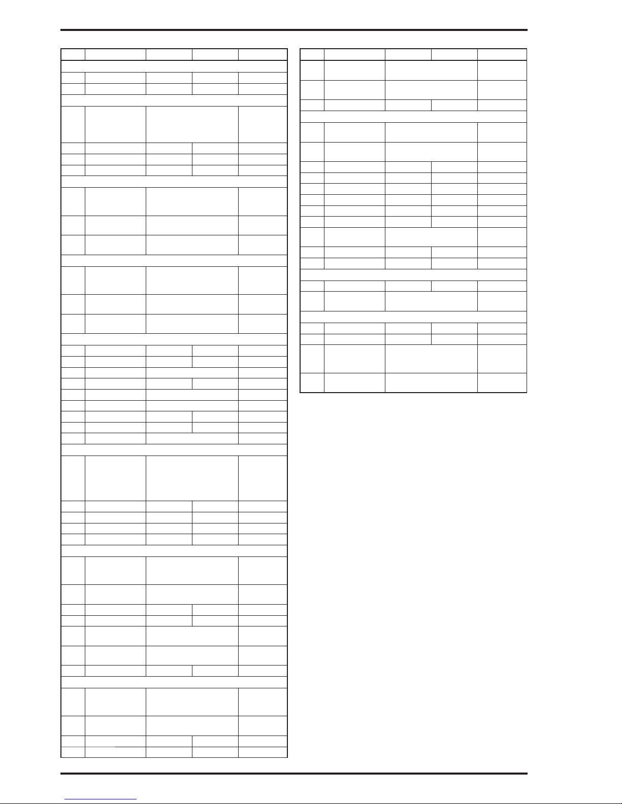
Push the PGM-key until “PROGRAM-MENU” is
displayed. Release the PGM-key and the fi rst parameter
group is displayed according to the parameter list on
page 2.
Using the arrow-keys it is possible to scroll through
the different available parameter groups. Note, If code
lock is activated, see page 6, the programmed 4-digit
access code must be entered to access the menu.
1. Internals
2. System settings
3. Output 1
4. Output 2
5. Pressure
6. Flow
7. Alarm 1
8. Alarm 2
9. PI Controller
10. AutoZero
11. Communication
When the desired parameter group is displayed, press
the PGM-key to select the group for programming. The
available parameters in the selected parameter group
is displayed on the bottom row.
Use the arrow-keys to select which parameter to
program and press the PGM-key.
A
A
Page 2
Page 2 of 8 [© AB Micatrone, mi-302gb_171025]
Nr Lead text Min Max Default
Internals
P00 SW: I/O
P01 SW: OPI
System settings
P03 Display dP
FLOW
dP+FLOW
SRC+CTRL
dP
P04 Damping [s] 0,0 9,9 1,0
P05 Access code 0000 9999 0000
P06 Number of OPI 1 3 1
Output 1
P08 Source dP
FLOW
CTRL
dP
P09 Signal V 0..10
2..10
0..10
P10 Signal mA 0..20
4..20
4..20
Output 2
P11 Source dP
FLOW
CTRL
CTRL
P12 Signal V 0..10
2..10
0..10
P13 Signal mA 0..20
4..20
4..20
Pressure
P15 MinCal [Pa]
P16 MaxCal [Pa]
P17 Unit dP Pa / mbar / iwc Pa
P18 Decimals 0 4 0
P19 Min range MinCal
P20 Max range MaxCal
P21 Min out MinRange MaxRange MinCal
P22 Max out MinRange MaxRange MaxCal
P23 Sign dP POS / NEG POS
Flow
P24 Unit fl ow l/s
m3/s
m3/h
m/s
cfm
l/s
P25 Decimals 0 4 0
P26 Max fl ow 0 32767 0
P27 Scale fl w 0 32767 0
P28 Set fl ow 0 32767 0
Alarm 1
P33 Mode OFF
HIGH
LOW
OFF
P34 Source dP
FLOW
dP
P35 Limit MinRange MaxRange 0
P36 Delay [s] 0 3600 0
P37 Reset MANUAL
AUTO
AUTO
P38 Beeper OFF
ON
OFF
P39 Mute time [s] 0 3600 0
Alarm 2
P40 Mode OFF
HIGH
LOW
OFF
P41 Source dP
FLOW
dP
P42 Limit MinRange MaxRange 0
P43 Delay [s] 0 3600 0
Nr Lead text Min Max Default
P44 Reset MANUAL
AUTO
AUTO
P45 Beeper OFF
ON
OFF
P46 Mute time [s] 0 3600 0
PI Controller
P47 Mode OFF
ON
OFF
P48 Source dP
FLOW
dP
P49 Set point MinRange MaxRange 0
P58 NZ [%] 1 50 2
P59 P-band [%] 0 100 0
P60 I-time [s] 0 999 10
P61 BZ [%] 0 100 0
P62 I-time BZ [s] 0 999 0
P63 Output DIRECT
REVERSE
REVERSE
P64 Min output [%] 0 100 0
P65 Max output [%] 0 100 100
AutoZero
P81 Interval [h] 0,0 60,0 0,0
P85 Output Volt 2
mA 2
mA 2
Communication
P73 Address 1 247 21
P74 Baud OFF / 600 128000 38400
P75 Parity NONE
ODD
EVEN
NONE
P76 Protect NO
YES
NO
Programming of a numeric value
Each digit in a numeric value is programmed separately.
Press PGM to begin programming. The selected digit
is fl ashing. Press the up-arrow key for digits between 1
and 9. When passing digit “9”, negative digits between
-9 and 0 are shown if they are allowed in the parameter
value. Confi rm each digit by pressing the PGM-key.
When all digits are programmed, press the PGM-key
to save the new value. The entire row is fl ashing to
confi rm programming. To abort ongoing programming,
press the ESC-key and then begin a new programming
with the PGM-key.
Note! It is always possible to abort or cancel incorrect
programming using the ESC-key unless you have
pressed the PGM-key after programming the last digit.
Programming of alternative units or values
Press the arrow-keys to select the desired alternative
unit or value. Press the PGM-key to save the change.
The entire row is fl ashing to confi rm programming.
Note! It is always possible to abort or cancel incorrect
programming using the ESC-key unless you have
pressed the PGM-key after selected unit/value.
End programming mode
Press the ESC-key to return to parameter group
selection display. Press the ESC-key a second time
to close the programming menu and return to the start
menu.
If no key has been pressed during 5 minutes, the
program menu is closed automatically.
PARAMETER LIST
Page 3
[© AB Micatrone, mi-302gb_171025] Page 3 of 8
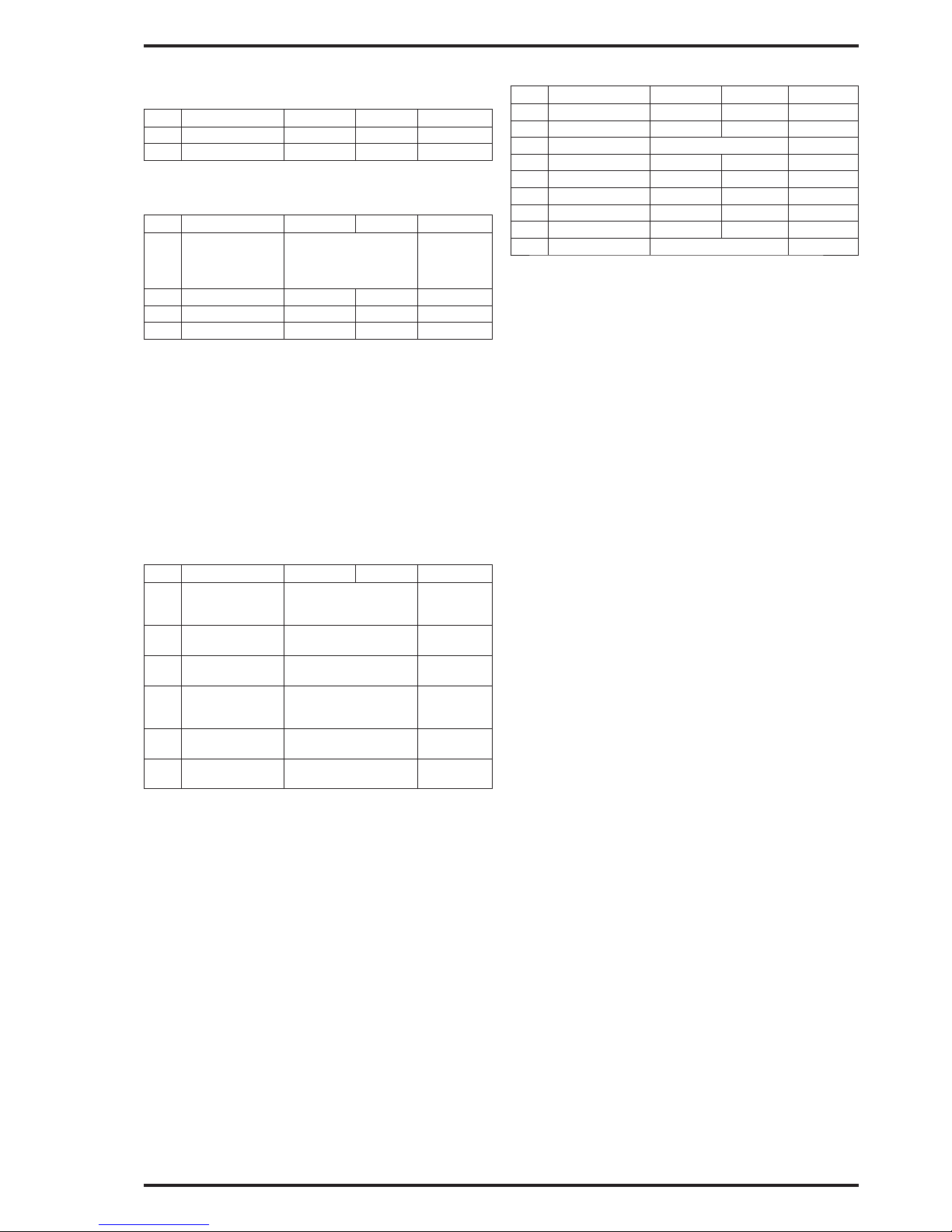
1. INTERNALS
Displays the program versions for the I/O-board
(motherboard) and Operator Interface (display).
No Lead text Min Max Default
P00 SW: I/O
P01 SW: OPI
2. SYSTEM SETTINGS
General settings in MF-PFT
No Lead text Min Max Default
P03 Display dP
FLOW
dP+FLOW
SRC+CTRL
dP
P04 Damping [s] 0,0 9,9 1,0
P05 Access code 0000 9999 0000
P06 Number of OPI 1 3 1
• P03 Display, select start menu to display. Select-
ing ‘SRC+CTRL’ show the selected source (SRC)
in the PI-controller + control output signal (CTRL).
• P04 Damping, programme, in seconds, the damp-
ing for the pressure output signal.
• P05 Access code, used for activating or deactivat-
ing the code lock, see page 6.
• P06 Number of OPI, number of operator interfaces
connected. See separate instruction.
3-4. OUTPUT 1 och OUTPUT 2
Settings for the two output signals
No Lead text Min Max Default
P08 Source dP
FLOW
CTRL
dP
P09 Signal V 0..10
2..10
0..10
P10 Signal mA 0..20
4..20
4..20
P11 Source dP
FLOW
CTRL
CTRL
P12 Signal V 0..10
2..10
0..10
P13 Signal mA 0..20
4..20
4..20
MF-PFT has 2 output signals which can be set to either
0..10 Volt, 2..10 Volt, 0..20 mA or 4..20 mA. Both Volt
and mA are simultaneously available for both outputs.
• P08/P11 Source, is used to select which measuring
value/signal (source) to direct as output signal. ‘dP’
is the pressure signal, ‘FLOW’ is the fl ow signal
and ‘CTRL’ is the control signal from the PI-controller.
• P09/P12 Signal V is used to switch between 0..10
Volt and 2..10 Volt output signal.
• P10/P13 Signal mA is used to switch between
0..20 mA and 4..20 mA output signal.
If the unit is fi tted with built-in automatic zero-setting
module MFM-ZP, it is connected to output 2 (Volt or
mA) and the parameter (P12 or P13) is hidden in the
parameter list. It is still possible to use the free output
signal on output 2 for the selected source.
5. PRESSURE
Settings for pressure measurement
No Lead text Min Max Default
P15 MinCal [Pa]
P16 MaxCal [Pa]
P17 Unit dP Pa / mbar / iwc Pa
P18 Decimals 0 4 0
P19 Min range MinCal
P20 Max range MaxCal
P21 Min out MinRange MaxRange MinCal
P22 Max out MinRange MaxRange MaxCal
P23 Sign dP POS / NEG POS
• P15/P16 MinCal[Pa] / MaxCal[Pa],
The MF-PFT is factory calibrated for a specifi c
range. The range is written on a label located on
the right side of the enclosure. The calibration is
always in Pascal (Pa). MinCal and MaxCal is the
calibrated pressure range in Pa. These values are
notes and not possible to change.
• P17 Unit dP, Select in which unit to display the
pressure. The alternatives are Pa, mbar or iwc
(inch water column).
• P18 Decimals, Number of decimals to show for the
pressure value. When using Pa as unit it is recommended not to use decimals.
In case any set value is above 32767 regardless of
where the decimal point is placed the adjustment is
not carried out.
E.g. If Set Point = 5000 and one decimal is se-
lected, the adjustment will not work since the value
5000,0 is greater than the allowed max value of
3276,7. Of the same reason, 500,0 cannot be
adjusted to 500,00.
• P19/P20 Min range / Max range
When programming a new unit, min and max limits
in the new unit are displayed in parameter Min
range and Max range. These values are notes and
not possible to change.
• P21 Min out, Lower limit for scaling the output
signal is set in pressure units, e.g. 10 Pa will result
at 10 Pa pressure the min output signal of, 0/2 V
resp. 0/4 mA.
• P22 Max out, Higher limit for scaling the output
signal is set in pressure units, e.g. 90 Pa will result
at 90 Pa pressure the max output signal of 10 V
resp. 20 mA.
• P23 Sign dP, If the transmitter is without zero
crossing, the MF-PFT will indicate a negative pressure similar to positive pressure (i.e. Without nega-
tive sign). When programming Sign dP = ‘NEG’
a negative sign (-) is shown in front of the current
value.
To change the range for the output signal, the Min out
and Max out are programmed. Programmed values
must be in the selected unit (Pa, mbar, iwc). When
scaling, be aware that the accuracy is always in
percent of the factory calibrated pressure range.
To measure and control the fl ow or velocity it is
necessary to connect the transmitter to fl ow sensors
with a known formula and k-factor.
Page 4
Page 4 of 8 [© AB Micatrone, mi-302gb_171025]
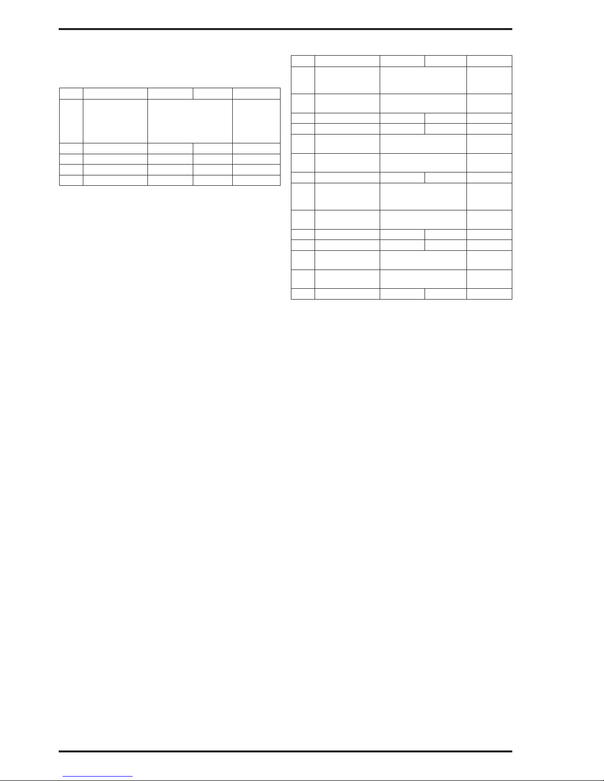
6. FLOW
To measure and control the fl ow or velocity it is
necessary to connect the transmitter to fl ow sensors
with a known formula and k-factor.
Settings for fl ow measuring.
No Lead text Min Max Default
P24 Unit fl ow l/s
m3/s
m3/h
m/s
cfm
l/s
P25 Decimals 0 4 0
P26 Max fl ow 0 32767 0
P27 Scale fl w 0 32767 0
P28 Set fl ow 0 32767 0
• P24 Unit fl ow, select a suitable unit for fl ow display,
l/s, m3/s, m3/h, m/s or cfm (cubic feet / minute).
• P25 Decimals, Number of decimals to show for the
fl ow value. In case any set value is above 32767
regardless of where the decimal point is placed the
adjustment is not carried out.
E.g. if Max Flow = 5000 and one decimal is se-
lected, the adjustment will not work since the value
5000,0 is greater than the allowed max value of
3276,7. Of the same reason, 500,0 cannot be
adjusted to 500,00.
• P26 Max fl ow, set the fl ow that correspond to the
pressure range on the MF-PFT.
• P27 Scale fl w, set the fl ow for max output signal,
10 V resp. 20 mA.
• P28 Set fl ow, Programme this parameter if adjust-
ing the displayed fl ow is necessary. Programme
the current fl ow using a reference fl ow measure-
ment. Max fl ow is re-scaled to correspond with the
reference measurement. If the unit is connected to
a computer system or similar, the receiving system
should also be programmed if the Scale fl w value
is higher than the new value of Max fl ow.
NOTE! Programming must be performed at the
same time as when the reference value is meas-
ured (The PGM-key is pressed for the last digit and
the value is stored).
The basic fl ow calculation used is made with √dP.
To have the display and the output corresponding
to the actual fl ow or velocity in the selected unit it is
necessary to make some calculations.
Different manu factors of fl ow measurement devices
have different calculation, but common for all is √dP.
Use the actual formula to calculate the max fl ow for the
factory calibrated measure range.
The calculated fl ow or velocity is then programmed
under Max fl ow in the selected unit. E.g. 5,0 m
3
/s. It
is possible to scale the fl ow range under Scale fl w.
When scaling the fl ow, note that the accuracy depends
on the “Max fl ow” range. Scale fl w must always
be set to the same or a lower value than Max fl ow.
E.g. 3,5 m3/s = 10 VDC.
The output signal is linear to the fl ow or velocity.
7-8. ALARM 1 and ALARM 2
Settings for two alarm limits.
No Lead text Min Max Default
P33 Mode OFF
HIGH
LOW
OFF
P34 Source dP
FLOW
dP
P35 Limit MinRange MaxRange 0
P36 Delay [s] 0 3600 0
P37 Reset MANUAL
AUTO
AUTO
P38 Beeper OFF
ON
OFF
P39 Mute time [s] 0 3600 0
P40 Mode OFF
HIGH
LOW
OFF
P41 Source dP
FLOW
dP
P42 Limit MinRange MaxRange 0
P43 Delay [s] 0 3600 0
P44 Reset MANUAL
AUTO
AUTO
P45 Beeper OFF
ON
OFF
P46 Mute time [s] 0 3600 0
MF-PFT has an alarm with two, each independent,
alarm limits. The alarm is acoustic with buzzer and
visual with LED (light emitting diode). Normal state
is indicated with green LED and alarm state with red
fl ashing LED on the lid. The acoustic alarm can be
disabled for each alarm limit. Red LED is activated
by the fi rst alarm state that occur. At the alarm limit,
the red LED is lit and after set time delay it begin to
fl ash. The display show which of the alarm limits that
triggered the alarm.
• P33/P40 Mode, select if the alarm should be trig-
gered for high or low level. Programme as ‘OFF’ to
deactivate monitoring.
• P34/P41 Source, Choose which measuring value
to be monitored. ‘dP’ = pressure, ‘FLOW’ = fl ow.
• P35/P42 Limit, set at which level the alarm to be
triggered.
• P36/P43 Delay [s], set time delay before alarm
state occur.
• P37/P44 Reset, ‘MANUAL’ if the alarm should be
reset manually by pressing the ESC-key or ‘AUTO’
if the alarm state should return automatically to
normal state when the level is back to normal.
• P38/P45 Beeper, ‘OFF’ disable the acoustic alarm.
‘ON’ if alarm state should sound.
• P39/P46 Mute time, is used to silence (mute) the
alarm for a set time in seconds when the ESC-
key is pressed. If the time is set to ‘0’, the alarm is
mute until the alarm is reset and a new alarm state
occur.
Page 5
[© AB Micatrone, mi-302gb_171025] Page 5 of 8
9. PI-CONTROLLER
Settings of PI-controller.
No Lead text Min Max Default
P47 Mode OFF
ON
OFF
P48 Source dP
FLOW
dP
P49 Set point MinRange MaxRange 0
P58 Nz [%] 1 50 2
P59 P-band [%] 0 100 0
P60 I-time [s] 0 999 10
P61 BZ [%] 0 100 0
P62 I-time BZ [s] 0 999 0
P63 Output DIRECT
REVERSE
REVERSE
P64 Min output [%] 0 100 0
P65 Max output [%] 0 100 100
MF-PFT has a PI-controller specially made for pressure
and fl ow control.
The controller could be programmed as a standard PIcontroller, but in most of the applications together with
pressure and fl ow control we recommend to program it
as an integral controller without P-band.
There are two programmable I-times. Outside a
desired limit on both sides of the set point it is possible
to have a shorter I-time and inside the limits a longer
I-time. The PI-control signal is directed to a desired
output in parameter group Output 1 or Output 2.
• P47 Mode, ‘ON’ activates Pi-controller, ‘OFF’ dis-
able the controller.
• P48 Source, select which measuring value to con-
trol. ‘dP’ = pressure, ‘FLOW’ = fl ow.
• P49 Set point, Set point value in the selected unit.
• P58 NZ [%], select desired neutral zone, normally
1..5%. Half zone above and half below set point
value. Set in percent of the measuring range.
• P59 P-band [%], normally not used for pressure or
fl ow control, default 0%. If P-band is programmed
to 0 % the P-function is disabled and the I-time is
calculated for a P-band of 100%.
• P60 I-time[s], set suitable I-time, normal 10s.
• P61 BZ [%], Break zone, used when you want to
reduce the control speed when surrounding the set
point.
• P62 I-time BZ, set I-time inside the break zone. En-
ter a longer I-time for a stable control when close
to the neutral zone.
• P63 Output, direction of the control output signal.
Normally ‘REVERSE’ (if the pressure or fl ow is
above set point, the output signal will decrease).
• P64 Min output, set a lower limit for the control
output signal in %.
• P65 Max output, set a higher limit for the control
output signal in %.
I-time
When programming as an I-controller there are two
possibilities.
• The same I-time over the full range. Normally used.
Program BZ = 000 and I-time BZ = 000. The I-time
should normally be longer than the time for the
damper motor etc. to go from min to max.
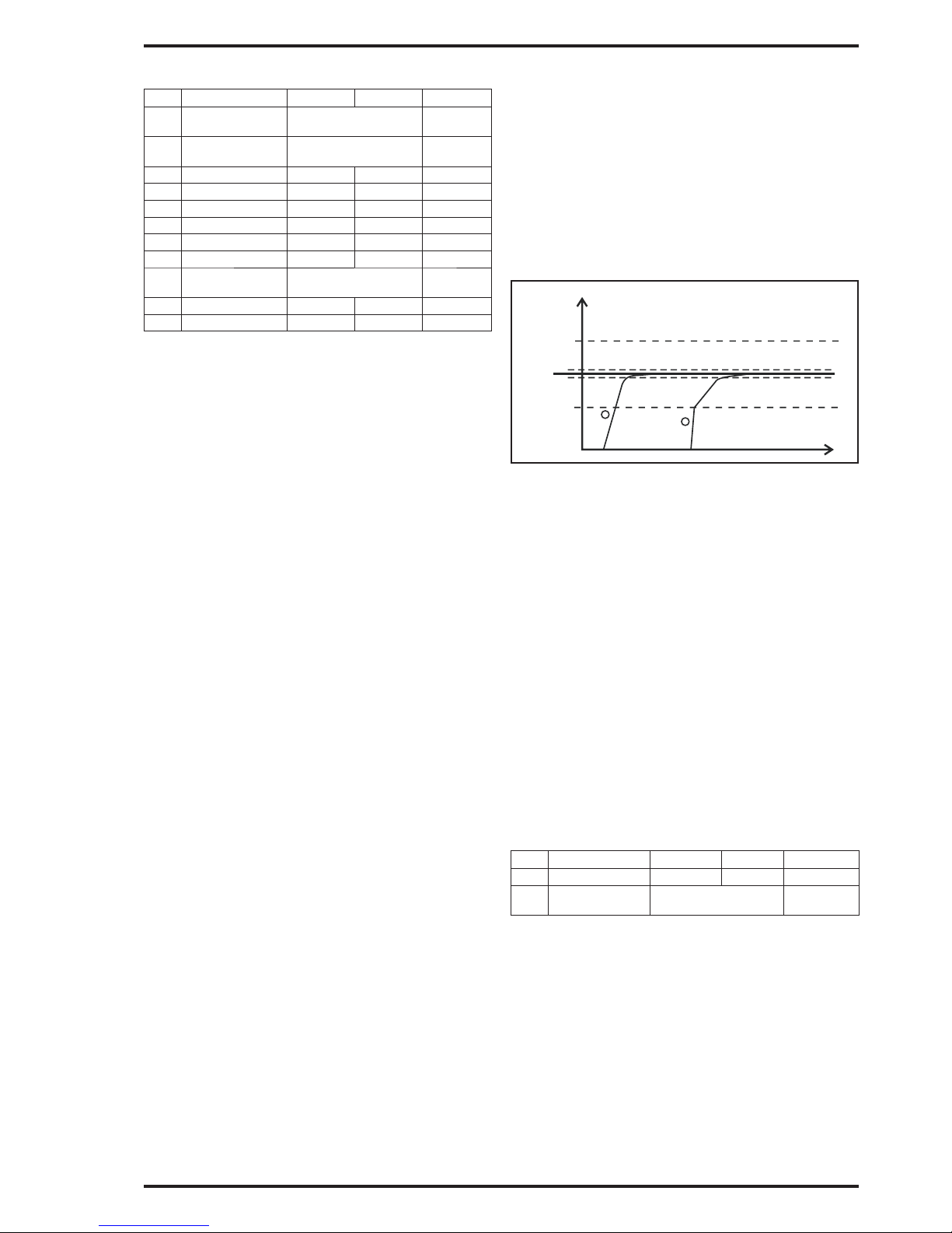
• Shifting between two I-times. The reason for working with two I-times is often that outside a set pressure or fl ow limit you want to have a fast response
and inside a slow response (see fi gure below).
BZ: limit for switching I-time. BZ is in % of the scaled
pressure or fl ow range. The set break zone, BZ, is
counted from the neutral zone, NZ, higher and lower
limit. The set value is on each side of the neutral zone
and moves with any changes in the neutral zone. If
the control output is not entering a stable position,
increase the I-time, you could also try to increase the
neutral zone.
Manual operation
Return to the start menu and select the display
option where output signal for PI-controller together
with pressure or fl ow is indicated. Which one that is
displayed is determined by what the PI controller is
programmed for.
“Flow / dP”
“AUTO 50.00 %”
Press PGM, ‘AUTO’ changes to ‘HAND’ and the output
signal can be set in % using the arrow keys.
Return to position ‘AUTO’ by pressing the PGM-key.
To display the programmed start menu, press the
ESC-key.
The display showing the text “PI-” in front of ‘HAND’
or ‘AUTO’ is not possible to use for manual operation.
10. AUTOZERO
Automatic zero adjustment. This parameter group is
only visible when solenoid valve MFM-ZP is installed.
No Lead text Min Max Default
P81 Interval [h] 0,0 60,0 0,0
P85 Output Volt 2
mA 2
mA 2
Using the optional built-in solenoid valve, automatic
zero adjustment can be set. During this process, the
displayed values and the output signals are halted.
After the zero adjustment is done in approx. 15
seconds, the transmitter restore to normal operation.
Zero adjustment can also be carried out manually
according to instructions on page 7.
• P81 Interval[h], The time between adjustment can
be set between 0,1 and 60 hours.
• P85 Output, Select which output the solenoid valve
is connected to.
DP/Flow
BZ
BZ
Setpoint
NZ
NZ
1
2
I-time BZ
I-time
I-time
sec.
Page 6

Page 6 of 8 [© AB Micatrone, mi-302gb_171025]
11. COMMUNICATION MODBUS
Modbus RTU through RS-485 serial connection.
This parameter group is only visible when communication module is installed.
No Lead text Min Max Default
P73 Address 1 247 21
P74 Baud OFF / 600 128000 38400
P75 Parity NONE
ODD
EVEN
NONE
P76 Protect NO
YES
NO
MF-PFT can be fi tted with a built-in expansion module
(Option) for network communication with a computer.
P73 Address, network address for MF-PFT, factory
default as 21.
P74 Baud, transfer rate, factory default 38400 baud.
P75 Parity, Parity bit in data transfer. Factory default
‘NONE’.
P76 Protect, Protection for parameter programming
through network communication. ‘YES’ = write
protection. This parameter can only be set to ‘NO’
using the MF-PFT keypad.
CODE LOCK PROTECTION
The code lock is used to protect against an authorized
programming. A four-digit code must be entered to
access the program menu and the functions menu. It
is still possible to read measuring values and operating
state without entering the access code.
At delivery, the code is set to ‘0000’, unless otherwise
agreed on. When the code is set to ‘0000’, the code
lock is inactivated and no protection against an
authorized programming is present.
Activation
To activate the code lock, a 4-digit code must be
programmed in parameter P05 Access code which is
found in parameter group System settings. The code
can not be ‘0000’, since this code is used to deactivate
the function. When a code has been programmed and
saved, the next time it will be necessary to enter the
code to access the program menu and the functions
menu.
Deactivating
The code lock can only by deactivated in the program
menu and therefore the access code must be available
to deactivate the code lock. Set the parameter P05
Access code to ‘0000’. The parameter is found in the
parameter group System settings.
Contact Micatrone if the code has been lost!
Entering the code
To access the program menu or functions menu it is
necessary to enter the access code.
Example:
1. Press the PGM-key to open the program menu.
Press the PGM-key until “PROGRAM- MENU” is
displayed.
2. Release the PGM-key. Following text is displayed
if key code is activated: “ENTER CODE:” and
“0***”.
3. The fi rst digit of the access code can be entered
using the arrow keys. When ready press the PGM-
key to continue with the next digit. Repeat until all
digits are entered.
4. When the 4 digits are entered, press the PGM-key
a fi nal time. The entered code is now compared
with the programmed code in parameter P05
Access code. If the codes match, the program
menu is displayed. The program menu is available
until it has been exited using the ESC-key.
5. If the entered access code is incorrect, the text
“INVALID CODE” is displayed during 2 seconds.
Restart from point 1.
6. By pressing the ESC-key, the entering code
operation is cancelled and the default start menu
is displayed.
FUNCTIONS MENU
Functions that are not used frequently on daily basis
are found in the functions menu. The functions menu
is accessed by pressing simultaneously the PGM
and ESC-key until the text “FUNCTIONS-MENU” is
displayed. If code lock is activated, see page , a valid
access code must be entered to access the menu.
Use the arrow keys to scroll through the different
functions, when displayed, select the desired function
by pressing the PGM-key. Exit the present menu by
pressing the ESC-key.
Functions
• Serial number Display the serial number xxxxx-xxx.
• Date of cal. Display the latest factory calibration
date.
• Reset Defaults Restore all data to the latest
factory calibration.
- List of params All values in the entire parameter
list are restored to default values at factory
delivery.
- Calibrations All calibrations are restored to
original values at factory delivery.
Note: fi eld calibrations will be reset.
• Calibration
- Input, fi ve-point calibration of the pressure
measurement
• Statistics Displays statistics for internal restarts.
- Power on, Number of normal power-on´s.
- Brown out, Number of restarts due to poor supply
voltage.
- Watchdog reset, Number of restarts due to runt-
ime error.
- SW error reset, Number of restarts due to soft-
ware error.
- Last reset cause, The cause for the latest restart.
- Operating time, Operating time since latest start.
Shown in days, hours and minutes (d:hh:mm).
Page 7
[© AB Micatrone, mi-302gb_171025] Page 7 of 8
Zero setting of pressure transmitter
Disconnect the pressure connections or place the
block valve in position calibration.
Press repeatedly on the ESC-key until the start menu
is displayed.
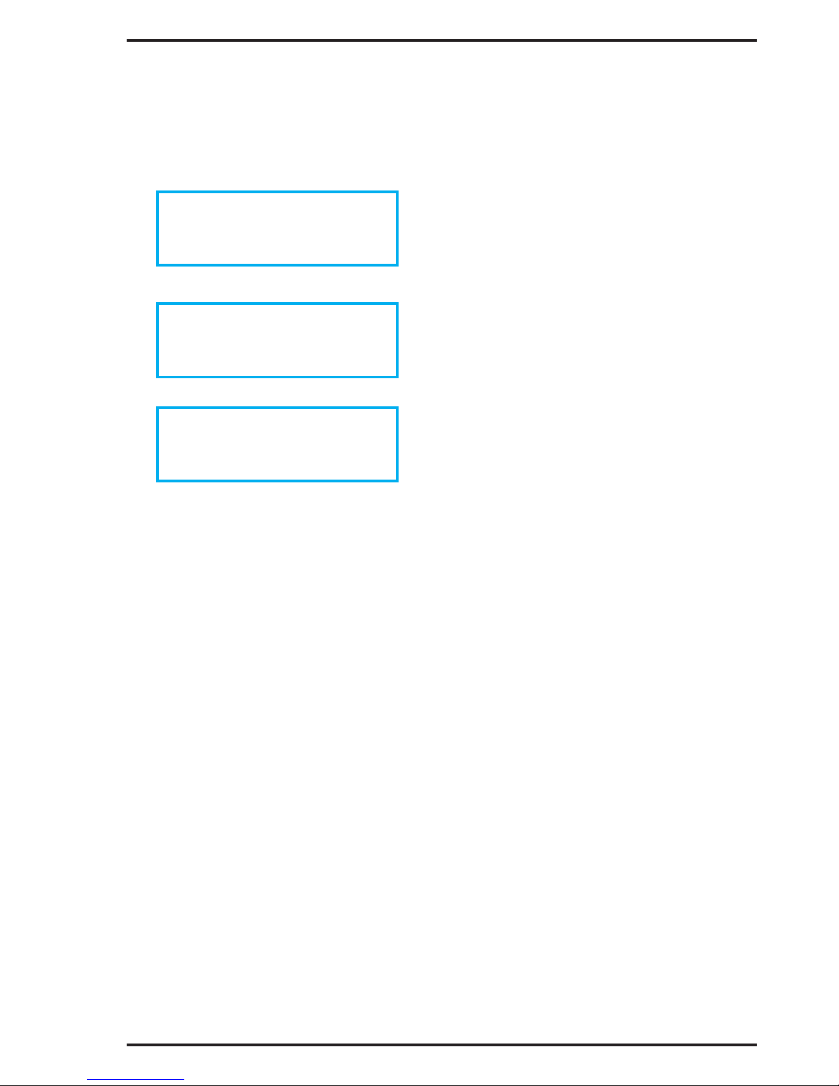
Press simultaneously on both arrow keys, keep
pressed until the display show:
Release the keys when following is shown:
When the zero setting is done, the display show:
Followed with the start menu.
If the transmitter is equipped with built-in auto zero
module, manual zero setting is done using the arrow
keys without the need to detach any tubes or changing
position of a connected mono block valve.
Calibration of MF-PFT
MF-PFT can be re calibrated against a pressure
reference.
1. Keep PGM and ESC pressed until following text
is displayed: “FUNCTIONS-MENU”.
2. Scroll using the arrow keys until “Calibration” is
displayed.
3. Press PGM. ‘Input’ is shown.
4. Press PGM. ‘Cal dP’ is shown.
5. Press PGM. The fi rst calibration point is shown.
Example:
MF-PFT (-50..50 Pa)
Pnt 1(5) = -50
6. Connect shown pressure. In this case, 50 Pa, to
the pressure connection marked negative [-].
7. Press the PGM-key and the MF-PFT will
start to measure the fi rst calibration point (9
measurements).
8. Press the PGM-key to continue with the second
calibration point, ESC aborts the calibration.
9. Proceed with all fi ve calibration points and
be careful to connect to the correct pressure
connection.
10. When all calibration points are done, following
text is shown:
“PGM=OK/ESC=ABORT”
11. The PGM-key will confi rm the calibration and
store the new calibration values.
12. The ESC-key will abort and cancel the calibration.
Press repeatedly on the ESC-key to return to the
start menu again.
Note! The pressure reference should comply with the
demand of desired accuracy in the measurement.
ZERO OFFSET
ZERO OFFSET
ADJUSTING
ZERO OFFSET
DONE
Page 8
AB Micatrone Telephone: +46-8-470 25 00
Aldermansvagen 3 Fax: +46-8-470 25 99
SE-171 48 SOLNA Internet: www.micatrone.se
SWEDEN E-mail: [email protected]
Page 8 of 8 [© AB Micatrone, mi-302gb_171025]
TECHNICAL DATA:
Display: Alphanumeric LCD
2 row, 2x16 characters
with backlight
Power supply: 24 ± 15% VAC
20...32 VDC
Pwr consumption: 7 VA (24 VAC)
3,5 W (24 VDC)
Pressure range: see label on enclosure.
Flow range:
(max 4 decimals)
l/s 0...32767
m3/s 0...32767
m3/h 0...32767
m/s 0...32767
cfm 0...32767
Measurement error: < ± 0,5 % of the pressure
range ± 0,5 Pa
Temperature drift: < ± 0,5 % /10 °C
Damping: 0,0...9,9 sec.
Output signal: Two analogue outputs,
0/2...10 VDC, 0/4...20 mA
selectable and scalable.
Both mA and Volt output
can be used simultaneously
Ambient temp: 0...50°C
Alarm: Two separate alarms for
high & low level, alarm
indication with red LED and
buzzer (joint)
Degree of protection: IP 65, ABS plastic
El-connection: 1 x 2,5 mm
2
/ terminal
Cable entries: 4 pcs M16x1.5mm
(cable glands not included)
Dimensions: WxHxD = 122x120x90 mm
Weight: 0,81 kg
MAINTENANCE:
Check zero settings every 6:th. month.
ACCESSORIES:
• Mounting kit for recessed mounting,
MFM-PANEL
• External transformer 24, 115, 230 VAC
• MODBUS communication module
• Solenoid valve for automatic zero-adjustment.
EMC/LVD:
Applied EU directives:
- EMC SS-EN 61000-6-3:2007 + A1:2011
SS-EN 61000-6-2:2005 + C1:2005
- LVD SS-EN 61010-1:2010
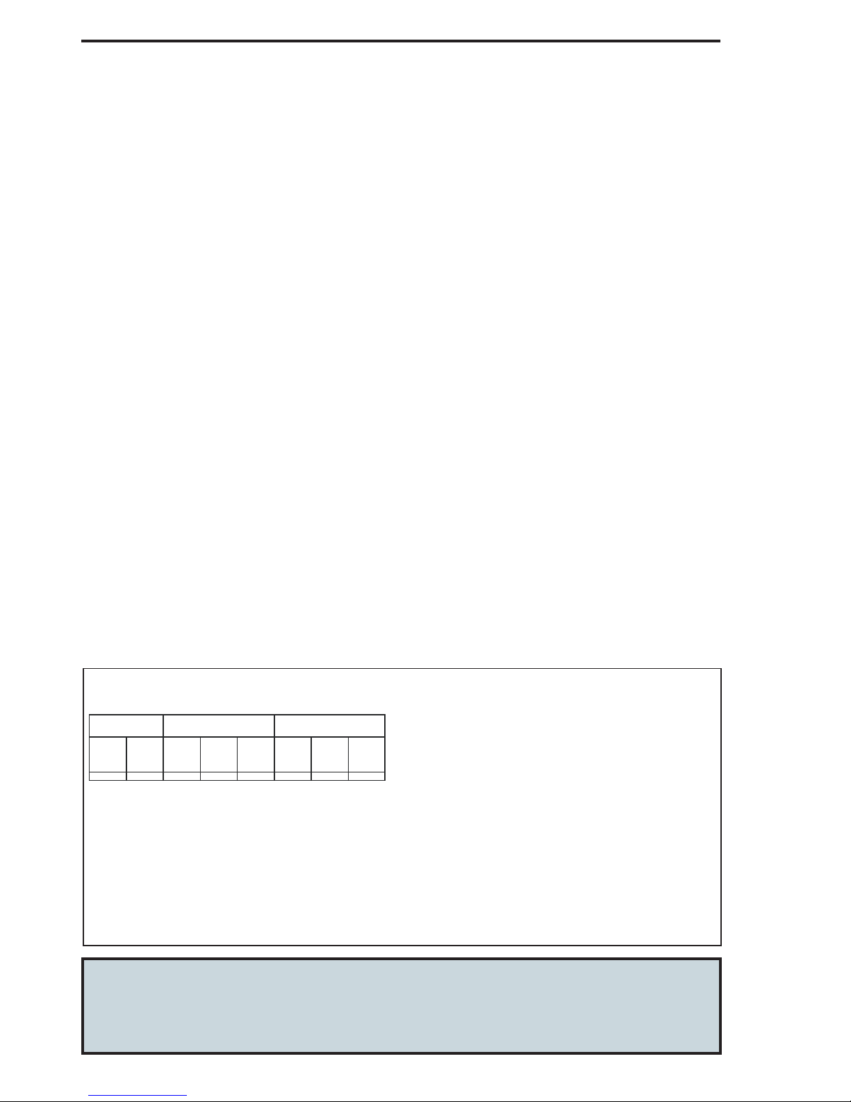
G (+)
G0 (-)
Volt (+)
Volt (+)
Output 124 VAC/VDC Output 2
Main connection board
Ground (-)
Ground (-)
mA (+)
mA (+)
ELECTRICAL CONNECTION:
 Loading...